EP3471371A1 - Authentication system for electronic control unit on a bus - Google Patents
Authentication system for electronic control unit on a bus Download PDFInfo
- Publication number
- EP3471371A1 EP3471371A1 EP18200198.2A EP18200198A EP3471371A1 EP 3471371 A1 EP3471371 A1 EP 3471371A1 EP 18200198 A EP18200198 A EP 18200198A EP 3471371 A1 EP3471371 A1 EP 3471371A1
- Authority
- EP
- European Patent Office
- Prior art keywords
- message
- bus
- authenticating
- transmitter
- receiver
- Prior art date
- Legal status (The legal status is an assumption and is not a legal conclusion. Google has not performed a legal analysis and makes no representation as to the accuracy of the status listed.)
- Granted
Links
- 238000004891 communication Methods 0.000 claims abstract description 8
- 230000005540 biological transmission Effects 0.000 claims description 40
- 238000000034 method Methods 0.000 claims description 8
- 230000010363 phase shift Effects 0.000 claims description 8
- 238000012545 processing Methods 0.000 claims description 7
- 230000000903 blocking effect Effects 0.000 claims description 4
- 125000004122 cyclic group Chemical group 0.000 claims description 3
- 230000007246 mechanism Effects 0.000 claims description 3
- 230000003287 optical effect Effects 0.000 claims description 3
- 230000008569 process Effects 0.000 claims description 3
- 230000002452 interceptive effect Effects 0.000 claims description 2
- 238000010586 diagram Methods 0.000 description 32
- 238000013459 approach Methods 0.000 description 14
- 239000003990 capacitor Substances 0.000 description 11
- 238000004804 winding Methods 0.000 description 8
- 101100368149 Mus musculus Sync gene Proteins 0.000 description 6
- 238000001514 detection method Methods 0.000 description 5
- 238000004458 analytical method Methods 0.000 description 4
- 230000000694 effects Effects 0.000 description 3
- 238000012795 verification Methods 0.000 description 3
- 238000013461 design Methods 0.000 description 2
- 238000012423 maintenance Methods 0.000 description 2
- 238000012986 modification Methods 0.000 description 2
- 230000004048 modification Effects 0.000 description 2
- 230000008439 repair process Effects 0.000 description 2
- 230000011664 signaling Effects 0.000 description 2
- 239000007787 solid Substances 0.000 description 2
- XUIMIQQOPSSXEZ-UHFFFAOYSA-N Silicon Chemical compound [Si] XUIMIQQOPSSXEZ-UHFFFAOYSA-N 0.000 description 1
- 230000009471 action Effects 0.000 description 1
- 230000008901 benefit Effects 0.000 description 1
- 238000004364 calculation method Methods 0.000 description 1
- 230000001934 delay Effects 0.000 description 1
- 230000000977 initiatory effect Effects 0.000 description 1
- 238000004519 manufacturing process Methods 0.000 description 1
- 238000012544 monitoring process Methods 0.000 description 1
- 238000003825 pressing Methods 0.000 description 1
- 229910052710 silicon Inorganic materials 0.000 description 1
- 239000010703 silicon Substances 0.000 description 1
- 230000007704 transition Effects 0.000 description 1
Images


Classifications
-
- G—PHYSICS
- G05—CONTROLLING; REGULATING
- G05B—CONTROL OR REGULATING SYSTEMS IN GENERAL; FUNCTIONAL ELEMENTS OF SUCH SYSTEMS; MONITORING OR TESTING ARRANGEMENTS FOR SUCH SYSTEMS OR ELEMENTS
- G05B23/00—Testing or monitoring of control systems or parts thereof
- G05B23/02—Electric testing or monitoring
- G05B23/0205—Electric testing or monitoring by means of a monitoring system capable of detecting and responding to faults
- G05B23/0208—Electric testing or monitoring by means of a monitoring system capable of detecting and responding to faults characterized by the configuration of the monitoring system
- G05B23/0213—Modular or universal configuration of the monitoring system, e.g. monitoring system having modules that may be combined to build monitoring program; monitoring system that can be applied to legacy systems; adaptable monitoring system; using different communication protocols
-
- H—ELECTRICITY
- H04—ELECTRIC COMMUNICATION TECHNIQUE
- H04L—TRANSMISSION OF DIGITAL INFORMATION, e.g. TELEGRAPHIC COMMUNICATION
- H04L9/00—Cryptographic mechanisms or cryptographic arrangements for secret or secure communications; Network security protocols
- H04L9/32—Cryptographic mechanisms or cryptographic arrangements for secret or secure communications; Network security protocols including means for verifying the identity or authority of a user of the system or for message authentication, e.g. authorization, entity authentication, data integrity or data verification, non-repudiation, key authentication or verification of credentials
- H04L9/3234—Cryptographic mechanisms or cryptographic arrangements for secret or secure communications; Network security protocols including means for verifying the identity or authority of a user of the system or for message authentication, e.g. authorization, entity authentication, data integrity or data verification, non-repudiation, key authentication or verification of credentials involving additional secure or trusted devices, e.g. TPM, smartcard, USB or software token
-
- H—ELECTRICITY
- H04—ELECTRIC COMMUNICATION TECHNIQUE
- H04L—TRANSMISSION OF DIGITAL INFORMATION, e.g. TELEGRAPHIC COMMUNICATION
- H04L12/00—Data switching networks
- H04L12/28—Data switching networks characterised by path configuration, e.g. LAN [Local Area Networks] or WAN [Wide Area Networks]
- H04L12/40—Bus networks
- H04L12/40052—High-speed IEEE 1394 serial bus
- H04L12/40104—Security; Encryption; Content protection
-
- G—PHYSICS
- G06—COMPUTING; CALCULATING OR COUNTING
- G06F—ELECTRIC DIGITAL DATA PROCESSING
- G06F13/00—Interconnection of, or transfer of information or other signals between, memories, input/output devices or central processing units
- G06F13/38—Information transfer, e.g. on bus
- G06F13/42—Bus transfer protocol, e.g. handshake; Synchronisation
- G06F13/4282—Bus transfer protocol, e.g. handshake; Synchronisation on a serial bus, e.g. I2C bus, SPI bus
-
- H—ELECTRICITY
- H04—ELECTRIC COMMUNICATION TECHNIQUE
- H04L—TRANSMISSION OF DIGITAL INFORMATION, e.g. TELEGRAPHIC COMMUNICATION
- H04L1/00—Arrangements for detecting or preventing errors in the information received
- H04L1/004—Arrangements for detecting or preventing errors in the information received by using forward error control
- H04L1/0056—Systems characterized by the type of code used
- H04L1/0061—Error detection codes
-
- H—ELECTRICITY
- H04—ELECTRIC COMMUNICATION TECHNIQUE
- H04L—TRANSMISSION OF DIGITAL INFORMATION, e.g. TELEGRAPHIC COMMUNICATION
- H04L12/00—Data switching networks
- H04L12/28—Data switching networks characterised by path configuration, e.g. LAN [Local Area Networks] or WAN [Wide Area Networks]
- H04L12/40—Bus networks
- H04L12/40006—Architecture of a communication node
- H04L12/40019—Details regarding a bus master
-
- H—ELECTRICITY
- H04—ELECTRIC COMMUNICATION TECHNIQUE
- H04L—TRANSMISSION OF DIGITAL INFORMATION, e.g. TELEGRAPHIC COMMUNICATION
- H04L63/00—Network architectures or network communication protocols for network security
- H04L63/06—Network architectures or network communication protocols for network security for supporting key management in a packet data network
-
- H—ELECTRICITY
- H04—ELECTRIC COMMUNICATION TECHNIQUE
- H04L—TRANSMISSION OF DIGITAL INFORMATION, e.g. TELEGRAPHIC COMMUNICATION
- H04L63/00—Network architectures or network communication protocols for network security
- H04L63/08—Network architectures or network communication protocols for network security for authentication of entities
- H04L63/0876—Network architectures or network communication protocols for network security for authentication of entities based on the identity of the terminal or configuration, e.g. MAC address, hardware or software configuration or device fingerprint
-
- H—ELECTRICITY
- H04—ELECTRIC COMMUNICATION TECHNIQUE
- H04L—TRANSMISSION OF DIGITAL INFORMATION, e.g. TELEGRAPHIC COMMUNICATION
- H04L63/00—Network architectures or network communication protocols for network security
- H04L63/10—Network architectures or network communication protocols for network security for controlling access to devices or network resources
- H04L63/101—Access control lists [ACL]
-
- H—ELECTRICITY
- H04—ELECTRIC COMMUNICATION TECHNIQUE
- H04L—TRANSMISSION OF DIGITAL INFORMATION, e.g. TELEGRAPHIC COMMUNICATION
- H04L63/00—Network architectures or network communication protocols for network security
- H04L63/12—Applying verification of the received information
- H04L63/123—Applying verification of the received information received data contents, e.g. message integrity
-
- H—ELECTRICITY
- H04—ELECTRIC COMMUNICATION TECHNIQUE
- H04L—TRANSMISSION OF DIGITAL INFORMATION, e.g. TELEGRAPHIC COMMUNICATION
- H04L63/00—Network architectures or network communication protocols for network security
- H04L63/14—Network architectures or network communication protocols for network security for detecting or protecting against malicious traffic
- H04L63/1408—Network architectures or network communication protocols for network security for detecting or protecting against malicious traffic by monitoring network traffic
- H04L63/1416—Event detection, e.g. attack signature detection
-
- H—ELECTRICITY
- H04—ELECTRIC COMMUNICATION TECHNIQUE
- H04L—TRANSMISSION OF DIGITAL INFORMATION, e.g. TELEGRAPHIC COMMUNICATION
- H04L63/00—Network architectures or network communication protocols for network security
- H04L63/16—Implementing security features at a particular protocol layer
- H04L63/164—Implementing security features at a particular protocol layer at the network layer
-
- H—ELECTRICITY
- H04—ELECTRIC COMMUNICATION TECHNIQUE
- H04L—TRANSMISSION OF DIGITAL INFORMATION, e.g. TELEGRAPHIC COMMUNICATION
- H04L63/00—Network architectures or network communication protocols for network security
- H04L63/20—Network architectures or network communication protocols for network security for managing network security; network security policies in general
-
- H—ELECTRICITY
- H04—ELECTRIC COMMUNICATION TECHNIQUE
- H04L—TRANSMISSION OF DIGITAL INFORMATION, e.g. TELEGRAPHIC COMMUNICATION
- H04L12/00—Data switching networks
- H04L12/28—Data switching networks characterised by path configuration, e.g. LAN [Local Area Networks] or WAN [Wide Area Networks]
- H04L12/40—Bus networks
- H04L2012/40208—Bus networks characterized by the use of a particular bus standard
- H04L2012/40215—Controller Area Network CAN
Definitions
- the present disclosure pertains to preventing unauthorized messages in communication systems.
- the disclosure reveals an authentication system having a communications bus, a transmitter connected to the bus, and a receiver connected to the bus.
- a physical layer signal may be applied by the transmitter to a message on the bus for authenticating the transmitter.
- the physical layer signal may incorporate an identifier (ID) of the transmitter.
- the receiver may receive the message and decode the physical layer signal on the message. Decoding the physical layer signal on the message may reveal the ID of the transmitter sending the message.
- the receiver may look up the ID on a list of IDs corresponding to transmitters approved to send the message, to determine whether the ID of the transmitter sending the message matches an ID on the list. Only if the ID of the transmitter matches an ID on the list, then the transmitter may be authenticated and authorized to send the message.
- the present system and approach may incorporate one or more processors, computers, controllers, user interfaces, wireless and/or wire connections, and/or the like, in an implementation described and/or shown herein.
- This description may provide one or more illustrative and specific examples or ways of implementing the present system and approach. There may be numerous other examples or ways of implementing the system and approach.
- Symbols may have virtually any shape (e.g., a block) and may designate hardware, objects, components, activities, states, steps, procedures, and other items.
- Authentication system and approach for electronic control unit on a bus may involve electronic control unit (ECU) radio frequency (RF) identification.
- ECU electronice control unit
- RF radio frequency
- a present system may integrate some of the identification/authentication functions into a transceiver in order to reduce costs.
- controller area network herein for illustrative purposes, but instead media such as other wired media, optical media, radio frequency media, or so on, may be used singularly or in combination.
- a CAN based bus used within the automotive environment does not necessarily appear to provide source authentication of messages on the bus. This may be a security issue.
- Cryptographic methods of providing source authentication may be problematic due to protocol restrictions and the complexities of key management in the repair environment.
- a feature of the present system can be unique because it may eliminate a need for costly and complex cryptographic key management.
- the system may provide an ability to authenticate the sources of a message on the CAN bus. This may in turn allow a higher level of security for connected cars and self-driving cars (aka, highly automated vehicles).
- This system may draw licensing revenue if offered to CAN bus transceiver vendors.
- IDS CAN intrusion detection system
- the present system may add a modulator function to the CAN bus transceiver such that each node on the network applies a unique analog fingerprint to the messages it sends.
- a secure/authenticating receiver may then check the message type and fingerprint to ensure that the message is from an authorized source. If the message is not from an authorized source, the authenticating receiver may block the message in such a way that all other ECUs on the bus also reject the unauthorized message.
- the present system may have an embedded software type.
- the software may run in a device/unit (e.g., firmware).
- a CAN transceiver vendor may be available, such as Texas Instruments or NXP.
- the system may improve automotive software CAN bus intrusion detection.
- Modern vehicles may incorporate on-board computing functions (e.g., electronic control units (ECUs) 13 connected by a controller area network (CAN) bus 12 as shown by architecture 11 in Figure 1 .
- the CAN bus may be a non-authenticated broadcast bus. This means that any ECU on the bus may send a message and other ECUs on the bus may assume that the message came from the proper source and may act upon the message.
- each ECU may need a unique cryptographic key to allow the source of messages to be cryptographically authenticated.
- OEM original equipment manufacturer
- the new module needs to be loaded with the appropriate key.
- Many issues may be associated with obtaining a copy of the original key.
- There may be also issues if the module is loaded with a new randomly generated key. That implies that all other modules in the vehicle need to be updated to recognize the new key/module pair.
- Many security issues arise with attackers manipulating the key management system to extract real keys or to inject false keys. Given the number of years a vehicle may be in service and the range of repair options (dealers, independent shops, and owners), using new parts or parts from a salvage yard, key management may become complex and error prone.
- the present system may allow ECUs on the bus to authenticate to a secure gateway/vehicle security module without the need for cryptography.
- a secure gateway/vehicle security module without the need for cryptography.
- the present system may be different than other CAN bus authentication proposals in that it explicitly takes advantage of an unbroken physical layer (as defined by an open system interconnect (OSI), a seven-layer model 14 or similar model) among ECUs on a bus.
- a diagram of Figure 2 may contrast a standard IP environment 15 with the CAN bus environment 16.
- OSI open system interconnect
- the physical layer signal may be received and regenerated by intermediate network nodes such as routers 19 and Ethernet switches 19. This may force the use of cryptography at a layer above the physical layer to provide source authentication.
- Figure 2 is a diagram of typical IP environment contrasted with the CAN environment.
- CAN bus environment 16 virtually all devices on the same CAN bus may be connected by the same physical medium 21.
- a physical layer signal applied by the sender 17 or transmitter may be observed by the receiver 18.
- the physical layer signal since it is preserved from a sender 17 to the receiver 18, may be used as an alternative to cryptographic authentication.
- an analog signal (at the physical layer) may be applied to the message being transmitted. This signal may be unique for each transmitter on the bus. Thus, if there are 20 ECUs on a CAN bus, then 20 different analog signals may be used. These signals may be differentiated by time (when the analog signal starts and stops), frequency, type of modulation (amplitude, frequency/phase shift) or any combination of these factors. One implementation is to encode an ID number of the transmitter within the signal.
- the analog signal does not necessarily need to cover all bits of the message as in traditional communications. The analog signal only needs to cover enough bits so that the detector in the authenticating receiver can determine the ECU ID.
- one authenticating receiver 23 may be employed per bus 25.
- Receiver 23 may contain electronics to detect the analog signal and then determine the ECU 24 bound to that analog signal. This in effect may identify the ECU 24 which is transmitting.
- the authenticating receiver 23 may then check the message being transmitted against the set of ECUs 24 authorized to transmit the message. If a transmitter is sending an authorized message, the authenticating receiver 23 may allow the message to be transmitted. If the transmitter is sending an unauthorized message, then authenticating receiver may block the message by corrupting the cyclic redundancy code (CRC) on the message ( Figure 9 ). The corrupted CRC may cause virtually all the other receivers on the bus to discard the message.
- CRC cyclic redundancy code
- the result may be that only messages that are sent from authorized ECUs 24 are accepted (e.g., processed) by receiving ECUs.
- the ECU source authentication system is shown in Figure 3a .
- a simplified version of applying a unique signal to a message from an ECU_n 24 by a dedicated modulator_n 26 to CAN bus 25 is shown in a diagram of Figure 3b .
- Each ECU 24 on a bus 25 which is to be authenticated may have a modulator 26 associated with its CAN bus transceiver 27.
- This modulator 26 may apply an analog signal to the messages sent by an ECU 24.
- the analog signal may be unique to the ECU 24 identifier.
- ECU_1 messages may be tagged with an analog signal 1.
- ECU_2 messages may be tagged with an analog signal 2, and so on.
- ECUs 24 may apply a similar analog signal (e.g., at the same frequency) but at different times. For example, ECU_1 may apply the analog signal to bits 0-3 of the messages while ECU_2 applies the same analog signal to bits 4-7 of the message.
- These ECUs 24 may apply the standard CRC check as specified by the CAN bus 25 protocol.
- the number of possible schemes (frequency, timing, modulation, binary encoding of an ID number, and so forth) for tagging CAN bus 25 messages may be nearly unlimited. No attempt is necessarily made here to enumerate all the possible combinations.
- the parameters that a designer should work with may include the following items. One may be frequency. The frequency of the signal may be varied such that a low frequency represents one tag and a higher frequency represents a second tag. Another may be timing. The timing of when the modulation is applied, may be varied. The modulation may start at different bit times within a message, and its duration may also vary. It is also possible to support various patterns such as, for example, modulation on for 3 bits, off for 4 bits and then on for 5 bits. A binary number may be encoded using a modulation scheme such as frequency shift keying, on/off keying or other encoding techniques.
- Another parameter may be waveform.
- waveforms which may be used for signaling in addition to a simple sine wave.
- quadrature phase shift keying may be used to encode many transmitter IDs.
- Another parameter may be amplitude.
- the amplitude of the signal may be varied. While amplitude variation is possible, it may introduce potential issues of noise, attenuation and other physical issues which could make signal detection more complex.
- Each ECU 24 on bus 25, which does not necessarily require source authentication, may have a legacy transceiver without a modulator.
- authenticating ECUs and non-authenticating ECUs may be mixed on the same bus and interoperate. There may be a risk that a non-authenticating ECU could transmit an unauthorized message.
- the reality of vehicle production may require that ECUs without authentication capability be accommodated until the supply chain is switched over to authenticating ECUs.
- the non-authenticating ECU may still apply a standard CRC check as specified by CAN bus protocol.
- the authenticating receiver should contain a list of messages (arbitration IDs) which require authentication.
- the authenticating receiver may detect the missing analog signature and mark the message as unauthorized by stomping on the CRC, thus causing all ECUs 24 to reject the non-authenticated message. Therefore, the non-authenticating ECU may still discard messages which the authenticating receiver marks as unauthorized by corrupting the CRC.
- an authenticating receiver 23 (sometimes called a vehicle security module). Vehicle manufacturers may place multiple authenticating receivers 23 in a gateway module which connects multiple CAN busses 25.
- the authenticating receiver 23 may perform the following functions.
- One may be demodulation.
- the CAN bus signal may be received and demodulated.
- a demodulator 31 may convert the analog signal on the CAN message to an input to the ECU identification 32. This input may indicate one or more characteristics of frequency, timing, and modulation type, or all three of the characteristics. Depending upon the analog scheme chosen for the implementation, demodulator 31 may also directly output the number of the transmitting ECUs 24.
- Another function may be ECU identification 32.
- the demodulator 31 outputs characteristics of the demodulated signal that are used by the ECU identification 32 function to determine the ECU identifier.
- the ECU identifier may be able to output an identity of the transmitting ECU 24 in digital form (e.g., 1, 2, and so on).
- intrusion detector 33 Another function may be intrusion detector 33.
- the intrusion detector 33 function may receive two inputs. The function may accept the ECU identifier from the ECU identification 32 function. It also may accept CAN bus 25 data from the transceiver 27 (typically co-located with demodulator 26). Intrusion detector 33 may use the message identifier (i.e., an arbitration ID) on the message together with the ECU identifier 32 to determine if the message is from an ECU 24 which is authorized to send the message. This determination may be implemented from a lookup table. If the intrusion detection 33 function determines that the transmitting ECU 24 is authorized to transmit the message, then intrusion detection does not necessarily invoke a function of a bit stomper 34.
- message identifier i.e., an arbitration ID
- bit stomper 34 may be activated. Bit stomper 34 may actively drive the signal on the CAN bus 25 to force a CRC error. The CRC error in turn may cause all ECUs 24 on bus 25 to reject the message.
- a result of the present system is that an ECU 24 may be prevented from transmitting an unauthorized message that is accepted by other ECUs on bus 25.
- CAN bus 25 signaling may be described in a context of the modulation scheme which adds an analog component.
- CAN bus 25 may be a two-wire system as shown in Figure 4 .
- the two lines 41 and 42 of bus 25 may carry CAN high (H) and CAN low (L) signals, respectively.
- Bus 25 may be terminated at both ends with 120 ohms across lines 41 and 42.
- CAN transceivers 27 may be connected across lines 41 and 42 with stubs 43 and 44, respectively.
- Each of differential signals or voltages 45 and 46 on CAN bus 25 may be a 5V or 3.3 V signal, as shown in Figures 5a and 5b , respectively.
- the signals CANL (CAN-L) and CANH (CAN-H) may have recessive logic H, dominant logic L, recessive logic H, and so on, along a time axis (t) versus typical bias voltage (V).
- Figure 6 is a diagram of a raw CAN bus signal waveform 47 without modulation. Like that of Figures 5a and 5b , the recessive logic H and dominant logic L portions of the waveform are revealed.
- a representation of the modulated CAN signal (i.e., with an analog signature 49 added) is shown in a waveform 48 in Figure 7 .
- the modulation does not necessarily have to be applied to every bit.
- the timing scheme may apply modulation 49 only at specific times.
- Waveform 48 shows modulation 49 occurring within the dominant portion of the signal. Modulation may also be applied during the recessive portion so long as it is within the noise margins.
- the modulated signal may still meet the CAN bus signal specifications.
- One or more modulation types may be selected from a group comprising frequency shift keying (FSK), amplitude shift keying, (ASK) on/off keying (OOK), phase shift keying (PSK), quadrature phase shift keying (QPSK), quadrature amplitude modulation (QAM) and continuous phase modulation (CPM).
- FSK frequency shift keying
- ASK amplitude shift keying
- OLK on/off keying
- PSK phase shift keying
- QPSK quadrature phase shift keying
- QAM quadrature amplitude modulation
- CPM continuous phase modulation
- the modulator function may be applied in any of four locations.
- the modulator function may be integrated in a CAN bus connector.
- a modulator chip may be embedded into the CAN bus connector connecting a legacy (i.e., with no modulator capability) ECU to the CAN bus.
- the modulator function may be integrated between the CAN wiring harness and the ECU.
- An additional "modulating connector” may be spliced between the existing CAN connector and the legacy ECU.
- the modulator function may be integrated as a chip on the ECU PCB.
- the modulator function may be implemented on a printed circuit board (PCB) of the ECU outside of the legacy transceiver.
- the modulator function may be integrated into the CAN transceiver.
- the modulation function may be integrated into the transceiver chip itself.
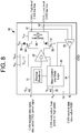
- Figure 8 is a diagram of a modulation scheme integrated within a transceiver 50.
- the modulation scheme i.e., the analog signature
- the modulation scheme may be applicable to both a traditional CAN as well as a newer CAN with a flexible data rate (CAN-FD).
- Line 51 may be for a CAN transmit data input, also called TXD, a driver input.
- Line 52 may be a CAN mode select, low power versus high speed.
- Line 51 may go to an input of an amp 53 that may provide inverted and non-inverted outputs, first and second outputs, respectively, to a gate of a P-channel FET 54 and to a gate of an N-channel FET 55.
- FET 54 may have a source connected to a cathode of a Zener diode 56 and a drain connected to a modulator circuit 58.
- FET 55 may have a drain connected to a cathode of a Zener diode 57 and a source connected to a ground (GND) terminal.
- GND ground
- An anode of diode 56 may be connected to a voltage supply (Vcc).
- An anode of diode 57 may be connected to modulator 58.
- An output 61 from modulator 58 may be a CANH, a high level CAN bus line.
- An output 62 from modulator 58 may be a CANL, a low level CAN bus line.
- Outputs 61 and 62 may be connected to a Schmitt trigger 63.
- An output 64 from trigger 63 may be CAN received data, also called RXD.
- Input 52 may go to a slope control and mode logic circuit 65, which may have an output to amp 53 and an output to trigger 63.
- a simple modulator may be placed in line between an ECU and CAN bus 25.
- the modulator may deliberately add a signature to a native electrical signal from the ECU.
- modulator implementation options It may be part of the wiring harness. It may be a dedicated IC placed after a transceiver 27 or be part of a CAN bus transceiver. Implementation may incorporate programmability at the factory or the field, or not be programmable.
- Figure 9 is a diagram of an electronic control unit fingerprint applied to a Controller Area Network message.
- the portions of an ECU fingerprint may incorporate one bit for a Start of Frame (SF) 81, 11 to 29 bits for a message identifier 82, 6 bits for control 83, up to 64 bits for data 84, 16 bits for CRC 85, 2 bits for ACK 86 and 7 bits for End of Frame (EF) 87.
- the ECU identification may be applied during the transmission of control bits and data bits.
- the bit stomping could be applied during the transmission of the control, data or CRC bits.
- Figure 10 is a diagram of a CAN bus signal 91 on a scope.
- Signal 91 may have a differential voltage of a dominant logic L signal at levels 92 and 93, for example.
- the waveform may reveal ringing 94, rise time 95 amplitude 96 and bit time variance 97 of signal 91.
- Figure 11 like Figures 5a, 5b , 6 , 7 , and 11 , shows a logic signal 101 having a recessive logic "1" signal and dominant logic “0" signal.
- logic signal 101 Corresponding to logic signal 101 are CAN-H and CAN-L signals 102 that have a magnitude of 2.5 volts each or a differential magnitude of about zero volts at the recessive logic H signal.
- the CAN-H and CAN-L signals 102 have magnitudes of 3.75 volts and 1.25 volts, respectively, and together have a differential magnitude of about 2.5 volts at the dominant logic L signal.
- Figure 12 shows the block diagram of a demonstration system.
- the purpose of the system may be to demonstrate that the RF (analog) identification signals and native CAN signals can coexist on the same physical channel (twisted pair).
- the timing of the transmission, decoding by a vehicle security module and enforcement decision may all be performed within the timing constraints of an operational CAN bus.
- the system may typically integrate the RF transmission and receiver functions in CAN transceivers in order to reduce cost size and power requirements.
- the authenticating transmitter may start transmitting an FSK modulated carrier when the device transmitter begins a transmission. Due to delays in responding to a start of transmission indication, this should occur ⁇ 1-2uS after the CAN transmission starts.
- the message may consist of a packet containing, at a minimum, a sync header and ID number for the CAN ECU.
- the ID number may be the base CAN ID (11 bit ID) in systems where multiple virtual devices exist in a single ECU.
- the data rate for the authentication transmission should be sufficiently fast such that the authentication message is complete well before the shortest CAN message can be transmitted. For a standard rate CAN bus ⁇ 1 MHz), this may be before the end of the 36th bit of the message (assuming a single 8 bit data field), or 36 microseconds (uS). The design must allow sufficient time for the authenticating receiver to process the message and act upon it.
- the authenticating receiver may use a microcontroller or hardware based logic (e.g., a gate array) to accomplish the required calculations within the required time.
- a microcontroller or hardware based logic e.g., a gate array
- the authenticating receiver of a vehicle security module may listen continuously for transmissions containing analog authenticating transmissions.
- VSM vehicle security module
- the message ID may be decoded and compared to the analog ID received, if any.
- the CAN message ID may be compared against the analog ID to see what types of commands this ECU is allowed to transmit. If this is a valid message for this particular ECU to transmit (i.e., a correct analog ID, allowed command type for this particular ECU), no action is necessarily taken.
- the authenticating receiver should short the bus (assert a dominant 1 bit) for more than 6 bit times before releasing the bus. This should invalidate the bus traffic as this is not necessarily a valid message for this ECU, real or spoofed, to send.
- the authenticating receiver should decode the command field of the message and determine if this device is allowed to transmit this command. If it is not allowed to transmit this command, then the authenticating receiver should short the bus (assert a dominant 1 ⁇ bit) for more than 6 bit times before releasing the bus. This may invalidate the bus traffic as this is not necessarily a valid message for this ECU, real or spoofed, to send.
- RF validating analog
- the authenticating receiver may still need to decode the message and determine if this is a valid command for this ECU to send. If it is not, then the VSM should short the bus (assert a dominant 1 bit) for more than 6 bit times before releasing the bus. This may invalidate the bus traffic as this is not necessarily a valid message for this ECU, real or spoofed, to send.
- An analysis for the system may include looking at the timing budget for the sender to apply the electronic control unit (ECU) identifier and for the receiver (policy enforcement) to decode the signal and make a decision whether or not to stomp on the CRC.
- ECU electronice control unit
- policy enforcement policy enforcement
- FIG 12 may also be regarded as a diagram of an instance of a present system 201, which may have an ECU module 202 and a vehicle security module 203.
- an ECU (#1) 204 may have an output (Tx.d) 205 connected to a transceiver 206 and an RF transmitter 207.
- ECU 204 may have another output (Tx/Rx) 208 connected to transceiver 206.
- An output (Rx.d) 209 from transceiver 206 may go to ECU 204.
- Transceiver 206 may be a Silicon Labs SLWSTK6221A 434 MHz dev kit. Transceiver 206 may be instead a circuit capable of applying an analog ID signal.
- Transceiver 206 may be connected to lines 211 and 212 of a bus 213.
- RF transmitter 207 may have lines 214 and 215 connected to a first winding of a transformer 218.
- a second winding of transformer 218 may have lines 221 and 222 connected to first terminals of capacitors 216 and 217, respectively.
- a nominal value of each capacitor may be 10 pf, but it may be another value as desired.
- Second terminals of capacitors 216 and 217 may be connected to lines 211 and 212, respectively, of bus 213.
- Transformer 218 may be a Minicircuits ADT2-1T-1P+ 1:2 transformer.
- Vehicle security module 203 may have an RF receiver/decoder 225.
- RF receiver/decoder 225 may be a TI CC1200 dev kit or other model as desired.
- An output line (Tx.d) 226 and line (Tx/Rx) 227 of RF receiver/decoder 225 may go to a transceiver 229.
- An output line (Rx.d) 228 may go to receiver/decoder 225.
- Output lines 231 and 232 may go from receiver/decoder 225 to a first winding of a transformer 233.
- a model of transformer 233 may be like that of transformer 218.
- Lines 234 and 235 may go from a second winding of transformer 233 to first terminals of capacitors 236 and 237, respectively.
- the second terminals of capacitors 336 and 337 may be connected to lines 211 and 212, respectively, of bus 213.
- Figure 13 is a diagram that shows an additional analysis of the transmission of the ECU identification. It may reveal a message packet 105.
- Bit 107 may be a start of a frame.
- Bits 102-112 may represent an arbitration field 108.
- Bit 13 may represent a remote transmitter request 109.
- Bit 14 may represent an ID extension bit 110.
- Bit 15 may represent a reserved bit 111.
- Bits 13-16 may represent an 8uS (microsecond) Tx start-up 112. Bits 16-19 may represent data length 113.
- Bits 20-27 represent 8 bit data 114.
- Bits 28-42 may represent a 15 bit CRC 115.
- Bits 17-27 may represent a 22uS transmission 116.
- Bits 28-36 may represent an 18uS stomp decision 117.
- Bit 43 may represent a CRC delimiter 118.
- Message packet 105 may be run on a CAN bus at 500 kbps.
- a message packet 106 may run on a CAN FD at 250 bkbps, which is one-half the speed that packet 105 is run.
- Bits 15, 17 and 18 may represent flexible data 121, bit rate switch 122 and error status indicator, respectively.
- Data length 113 may be represented by bits 19-22.
- Eight-bit data length 114 may be represented by bits 23-30.
- a seventeen bit CRC 115 may be represented by bits 31-47.
- CRC delimiter 118 may be represented by bit 48.
- a 20uS mark 125 may occur at bit 10 in packet 105. That may be a 40uS mark 126 at bit 10 in packet 106. Each bit may be 2uS in packet 105 and 4uS in packet 106.
- Bus Tx startup 112 may be during bits 12 and 13 in packet 106.
- An 88uS transmission 116 may be during bits 14-36.
- a 20uS stomp decision 117 may be during bits 37-41. Seven bits 119 may remain after stomp decision 117.
- the authenticating transmitter should decode the ECU 10 field while monitoring both the transmitter enable line and transmitter data line on the ECU in order to determine if the ECU to which the ID transmitter is attached has actually taken control of the bus. This may be done by decoding the transmitted address. Normally, a non-bit-stuffed ECU 10 field may be 11 bits in length. Because CAN data is limited to a run length of 5 bits, maximum, this could expand the 10 field to as long as 13 bits if there are two sequences of run length limits in the 10 field.
- the authenticating RF transmitter should monitor the transmitted 10 field and determine if bit-stuffing has occurred in order to properly determine when the end of the 10 field occurs. If the transmitter is still active after the last bit of the bit-stuffed ID field, then the device may have taken control of the bus and the authenticating transmitter may be engaged to send the RF ID data to the authenticating receiver (VSM).
- VSM authenticating receiver
- Figure 14 is a diagram of a packet 130. Some differences may be apparent when compared to packet 106.
- Message packet 130 may be run on a CAN at 125 kbps.
- An 8uS Tx startup 112 may occur during bit 12, which is the remote Tx request. Transmission time available may occur from bit 13 to about one-fourth way through bit 34.
- a stomp decision 117 may run from about one-fourth way through bit 34 up to bit 37. Seven bits 119 may remain after bit 36 through bit 43.
- There may be a 4 byte sync of 32uS beginning at bit 22.
- a 48uS stomp decision 117 may begin during bit 31.
- Figure 15 may be a diagram of a timing analysis that shows that the system can perform the needed transmission and decoding in order to prevent a successful transmission of messages from unauthorized sources.
- RF startup time for CC1200 transition may be from Rx to Tx state (43uS). Reducing the preamble from 40 to 20 symbols may increase the stomp decision time to 61uS. This should be more than adequate, even with allowing additional time to initialize the Tx and decode the message in the Rx.
- the RF symbol rate is 500ksps due to using 4(G) FSK transmission to achieve 1 Mbps throughput.
- the RF components may be implemented outside of the CAN transceiver chip.
- the proof of concept design for the transmitting ECU is shown herein.
- Figure 15 has the diagram of a packet 135 running on a 125 kbps CAN. After bit 11, there may be a 43uS Tx startup. The pattern of packet 135 may be the same as packet 130. There may be a 200uS total time available after bit 11. A 40uS preamble with 20 symbols may start during bit 17. There may be a 4 byte sync of 32uS beginning during bit 21. Bus data may occur for about one bit after the sync. A 16uS CRC may begin during bit 26. A 61uS stomp decision may occur after the CRC. Seven bits may remain after the stomp decision. A 96uS verification transmission length may begin during bit 17.
- Packet 135 may begin with a start of frame bit 107.
- An arbitration field 108 may follow bit 107.
- a Tx start up 112 may run from field 108 to a start of a 20 symbol preamble 136.
- Sync bits 137 may follow preamble 136 up to data 138.
- CRC 139 may go from data 138 to a stomp decision 117. If there is no stomp decision, then CRC 139 may continue, including 7 bits remaining 119, to CRC delimiter 118.
- Bits following Tx start up 112 up to stomp decision 117 may be a verification transmission length 141. Total time available may run from a beginning of Tx start up 112 through stomp decision 117.
- FIG 16 is a diagram showing a transmit portion of the system.
- a chip CC1200 may ideally wake on Tx/Rx->Tx and watch the Tx.d and Rx.d data lines to determine if ECU #1 has: 1) Started to transmit; 2) Captured the bus by comparing the transmitted ID to the received ID in that a mismatch indicates that the bus was not captured; and 3) Finished transmitting the ECU ID field so that a radio can start sending the ECU ID.
- a transmission may be initiated by pressing the button attached to the ECU.
- An LED may light up to indicate that a bus transaction has started.
- the transceiver may switch from receive to transmit and send out a preamble, sync sequence, the ECU ID#, and the message CRC. This may identify the device originating the transmission and the validity of the transmission may be determined by the vehicle security module.
- a CC1200 need only delay after the start of the transmission because there will be necessarily no devices contending for the bus.
- a receive function of the RF transceiver can be used only to hold the transmit frequency. This appears necessary to speed up the time from transmitter initiation to actual RF output.
- FIG 16 may also be regarded as a diagram of a transmitting portion 140 of a version of the present system.
- a freescale/NXP transceiver 142 that may incorporate an ECU 143 and a transceiver 144.
- ECU 143 may have a transmit button 145 and an LED indicator 146.
- Transmitting portion 140 may further incorporate a CC 1200 RF transceiver 147.
- Transceiver 147 may be instead one of several other available models.
- ECU 143 may have an output (Tx.d) 148 to transceiver 144 and transceiver 147, and an output (Tx/Rx) 149 to transceiver 144 and transceiver 147.
- Transceiver 144 may have an output (Rx.d) 151 to ECU 143 and transceiver 147.
- Transceiver 144 may have connections to lines 152 and 153 of a bus 154.
- Transceiver 147 may have connections to lines 155 and 156 to a first winding of a Minicircuits ADT2-1T-1P+ 1:2 transformer 157.
- Transformer 157 may be instead one of several other available models.
- a second winding of transformer 157 may be connected to lines 158 and 159, which in turn may be connected to first terminals of capacitors 161 and 162, respectively.
- the second terminals of capacitors 161 and 162 may be connected to lines 152 and 153, respectively, of bus 154.
- Nominal values of capacitors 161 and 162 may be 10 pf, or other values as desired.
- the receiver (vehicle security module which may perform enforcement) is shown in Figure 17 .
- the RF receiver components may typically be integrated in the CAN bus transceiver.
- CC1200 may be virtually always in a receive mode listening for an RF signal on the bus.
- the microcontroller may decode the bus ID field and wait for a message from the CC1200 indicating that it received data.
- the microcontroller may retrieve the data and compare the bus address with the ECU ID.
- the RF ID and the CAN ID may be compared to a table of allowed RF ID and CAN ID pairs. If the table indicates they are allowed to communicate, nothing appears to happen and the microcontroller may go back to sleep. If the table indicates that this is not an allowed transaction, the microcontroller may turn on the CAN transceiver and send out either a 7 byte sequence of solid zeros or a hash of random data to jam the bus and invalidate the transmission.
- the microcontroller may turn on the CAN transceiver and send out either a 7 byte sequence of solid zeros or a hash of random data to jam the bus and invalidate the transmission. After the 7 byte quash/jam sequence is sent, the VSM may go back to sleep.
- a red LED may indicates that the VSM has quashed a transmission.
- a green LED may indicate that an authenticated transmission has occurred.
- a red LED may indicate that an invalid transmission was detected. The LED indication may be for illustrative purposes.
- Figure 17 may also be regarded as a diagram of a receiving portion 150 of a version of the present system.
- Portion 150 may be regarded as a vehicle security module.
- a microcontroller 164 may have an output (Tx.d) 166 to a transceiver 165 and also an output (Tx/Rx) 167 to transceiver 165.
- Transceiver 165 may have an output (Rx.d) 168 to microcontroller 164.
- Microcontroller 164 may be a Cortex M4 @ 200 MHz or a Cortex A9 @ 1 GHz.
- Microcontroller 164 may be one of several other available models.
- Microcontroller 164 may have an LED indicator 169.
- Lines 171 and 172 may connect microcontroller 164 to a CC1200 RF transceiver 174.
- Transceiver 165 may be connected to lines 152 and 153 of bus 154.
- Transceiver 174 may have lines 175 and 176 connected to a first winding of a Minicircuits ADT2-1T-1P+ 1:2 transformer 177.
- Transformer 177 may be instead one of several other available models.
- a second winding of transformer 177 may be connected to lines 178 and 179, which in turn may be connected to first terminals of capacitors 181 and 182, respectively.
- the second terminals of capacitors 181 and 182 may be connected to lines 152 and 153, respectively, of bus 154.
- Nominal values of capacitors 181 and 182 may be 10 pf, or other values as desired.
- an authentication system may incorporate a bus, a transmitter connected to the bus, and a receiver connected to the bus.
- a physical layer signal may be applied by the transmitter to a message on the bus for authenticating the transmitter.
- the physical layer signal may incorporate an identifier (ID) of the transmitter.
- the receiver may receive the message and decode the physical layer signal on the message.
- a decoding of the physical layer signal on the message may reveal the ID of the transmitter sending the message.
- the receiver may look up the ID on a list of IDs corresponding to transmitters approved to send the message, to determine whether the ID of the transmitter sending the message matches an ID on the list. If the ID of the transmitter matches an ID on the list, then the transmitter may be authenticated and authorized to send the message.
- the message sent by the transmitter that is received by the receiver may be processed by the receiver. If the transmitter cannot be authenticated, then the message sent by the transmitter that is received by the receiver may be blocked and not processed by the receiver.
- a message having a physical layer signal may be received by the receiver without interference to an ability of the receiver to receive and decode another message that is a normal signal digitized data message per a communications standard.
- the bus may be a controller area network (CAN).
- the message may be a CAN message.
- the CAN message may have a dominant portion and a recessive portion.
- the physical layer signal may be applied to a dominant portion, a recessive portion, or both a dominant and a recessive portion of the CAN message.
- one or more media may be selected from a group incorporating wired media, optical media, radio frequency media, that may be used singularly or in combination for the system.
- the bus may incorporate one or more additional receivers that detect the blocking of the message by the receiver that checks the ID decoded from the physical layer signal on the message from the transmitter and determines that the ID of the transmitter does not match an ID on a list of IDs corresponding to transmitters approved to send the message, and in turn blocks the message.
- the system only one receiver on the bus needs to receive the message and decode the physical layer signal applied to the message.
- the system only needs one authenticating receiver because the bit stomping function, together with the CRC allows the authenticating receiver to block other receivers from receiving the message.
- the system may have one or more receivers on the bus which can decode the physical layer signal applied to the message.
- bit stomping function is not necessarily the only way to block an unauthorized message. Having one authenticating receiver which performs bit stomping (invalidating the CRC) may be a cost effective way of implementing the system because one authenticating receiver can block the unauthorized message from all receivers.
- a system could have two or more authenticating receivers which decode the authentication signal and simply prevent the local node from processing the message, i.e., they do not necessarily do bit stomping to prevent other nodes from receiving the message.
- the receiver may allow the message to be processed without interfering with the message.
- the receiver may block a processing of the message by asserting a signal on the bus that causes a cyclic redundancy code (CRC) associated with the message to be corrupted.
- CRC cyclic redundancy code
- One or more nodes on the bus having receivers may detect corruption of the CRC associated with the message and thus may not process the message.
- Two or more receivers on the bus may receive and decode a physical layer signal on the message to obtain an ID of the transmitter of the message and determine whether the ID matches an ID on a list of IDs of transmitters authorized to send the message.
- the any one of the two or more receivers may allow the message to be processed by a local processor. If the any one of the two or more receivers determines that the entity was not authorized to transmit the message, then the any one of the two or more receivers may block a processing of the message by the local processor.
- the transmitter may apply a modulated signal to the physical layer signal to code an ID for authentication of the transmitter.
- One or more modulation types may be selected from a group having frequency shift keying (FSK), amplitude shift keying, (ASK) on/off keying (OOK), phase shift keying (PSK), quadrature phase shift keying (QPSK), quadrature amplitude modulation (QAM) and continuous phase modulation (CPM).
- the bus may incorporate one of the following receiver and transmitter combinations of components: one or more authenticating receivers, and one or more authenticating transmitters; one or more authenticating receivers, one or more authenticating transmitters, and one or more non-authenticating receivers; one or more authenticating receivers, one or more authenticating transmitters, and one or more non-authenticating transmitters; one or more authenticating receivers, one or more authenticating transmitters, and one or more non-authenticating transmitters; one or more authenticating receivers, one or more authenticating transmitters, one or more non-authenticating receivers, and one or more mon-authenticating transmitters; only one authenticating receiver and only one authenticating transmitter; only one authenticating receiver, only one authenticating transmitter, and one or more non-authenticating receivers; only one authenticating receiver, only one authenticating transmitter, and one or more non-authenticating transmitters; or only one authenticating receiver, only one authenticating transmitter, one or more non-authenticating receivers, and one or more non-authenticating transmitters.
- a receiver and transmitter combination that has components that perform authenticating functions and non-authenticating functions may interoperate in accordance with a security policy applied by one or more authenticating components.
- An authentication approach may incorporate applying a physical layer authentication signal to a message to be sent by a transmitter on a bus; decoding an identifier (ID) from the physical layer authentication signal on the message to be received by a receiver on the bus; and looking up the ID on a list of IDs corresponding to transmitters approved to send the message, to determine whether the ID decoded from the physical layer authentication signal matches an ID on the list. If the ID matches an ID on the list, then the message on the bus may be authorized. If the ID matches no ID on the list, then the message on the bus may be unauthorized.
- ID identifier
- the approach may further incorporate accepting and processing the message on the bus if the message is authorized, and blocking the message on the bus if the message on the bus is unauthorized.
- Only one receiver on the bus may receive the message and decode the physical layer authentication signal applied to the message.
- a mechanism for authenticating transmissions may incorporate a transmitting entity, a receiving entity, and a bus connected to the transmitting entity and the receiving entity.
- a physical layer signal may be applied by the transmitting entity to a message on the bus to authenticate the transmitting entity.
- the physical layer signal may incorporate an identifier (ID) of the transmitting entity.
- the receiving entity may receive the message and decode the physical layer signal on the message.
- a decoding of the physical layer signal on the message may reveal the ID of the transmitting entity sending the message.
- the receiving entity may look up the ID on a list of IDs corresponding to transmitting entities approved to send the message, to determine whether the ID of the transmitting entity sending the message matches an ID on the list. If the ID of the transmitting entity matches an ID on the list, then the transmitting entity may be authenticated. If the ID of the transmitting entity does not match an ID on the list, then the transmitting entity may be not authenticated.
- the transmitting entity If the transmitting entity is authenticated, the message sent by the transmitting entity that is received by the receiving entity may be processed by the receiving entity. If the transmitting entity is not authenticated, then the message sent by the transmitting entity that is received by the receiving entity may be blocked and not processed by the receiving entity.
- a message having a physical layer signal may be received by the receiving entity without interference to an ability of the receiving entity to receive and decode another message that is a normal signal digitized data message per a communications standard.
Landscapes
- Engineering & Computer Science (AREA)
- Computer Security & Cryptography (AREA)
- Computer Networks & Wireless Communication (AREA)
- Signal Processing (AREA)
- General Engineering & Computer Science (AREA)
- Computer Hardware Design (AREA)
- Computing Systems (AREA)
- Theoretical Computer Science (AREA)
- General Physics & Mathematics (AREA)
- Physics & Mathematics (AREA)
- Power Engineering (AREA)
- Small-Scale Networks (AREA)
- Automation & Control Theory (AREA)
Abstract
Description
- The present disclosure pertains to preventing unauthorized messages in communication systems.
- The disclosure reveals an authentication system having a communications bus, a transmitter connected to the bus, and a receiver connected to the bus. A physical layer signal may be applied by the transmitter to a message on the bus for authenticating the transmitter. The physical layer signal may incorporate an identifier (ID) of the transmitter. The receiver may receive the message and decode the physical layer signal on the message. Decoding the physical layer signal on the message may reveal the ID of the transmitter sending the message. The receiver may look up the ID on a list of IDs corresponding to transmitters approved to send the message, to determine whether the ID of the transmitter sending the message matches an ID on the list. Only if the ID of the transmitter matches an ID on the list, then the transmitter may be authenticated and authorized to send the message.
-
-
Figure 1 is a diagram of what modern vehicles may incorporate in terms of on-board computing functions; -
Figure 2 is a diagram that contrasts a standard internet protocol environment with a controller area network bus environment; -
Figure 3a is a diagram of an electronic control unit source authentication system; -
Figure 3b is a diagram of a simplified version of applying a unique signal to a message from an electronic control unit by a dedicated modulator; -
Figure 4 is a diagram of a bus incorporating a two-wire system; -
Figures 5a and 5b are diagrams of differential signals or voltages on a bus; -
Figure 6 is a diagram of a raw bus signal waveform without modulation; -
Figure 7 is a diagram of a representation of a modulated signal; -
Figure 8 is a diagram of a modulation scheme integrated within a transceiver on a chip; -
Figure 9 is a diagram of an electronic control unit fingerprint applied to a controller area network message; -
Figure 10 is a diagram of a controller area unit bus signal on an oscilloscope; -
Figure 11 is a diagram of a waveform having a recessive logic signal and a dominant logic signal; -
Figure 12 shows a diagram of a system for authentication of components for allowing transmission of messages; -
Figures 13 ,14 and 15 are diagrams of message packets used for timing analysis in aiding of determining authentication with transmission and decoding in order to prevent a successful transmission of messages from unauthorized sources; -
Figure 16 is a diagram of a transmit portion of an example of the present system; and -
Figure 17 is a diagram of a receiving portion of an example of the present system. - The present system and approach may incorporate one or more processors, computers, controllers, user interfaces, wireless and/or wire connections, and/or the like, in an implementation described and/or shown herein.
- This description may provide one or more illustrative and specific examples or ways of implementing the present system and approach. There may be numerous other examples or ways of implementing the system and approach.
- Aspects of the system or approach may be described in terms of symbols in the drawing. Symbols may have virtually any shape (e.g., a block) and may designate hardware, objects, components, activities, states, steps, procedures, and other items.
- Authentication system and approach for electronic control unit on a bus may involve electronic control unit (ECU) radio frequency (RF) identification. A present system may integrate some of the identification/authentication functions into a transceiver in order to reduce costs.
- The present system and approach may use controller area network (CAN) herein for illustrative purposes, but instead media such as other wired media, optical media, radio frequency media, or so on, may be used singularly or in combination.
- A CAN based bus used within the automotive environment does not necessarily appear to provide source authentication of messages on the bus. This may be a security issue. Cryptographic methods of providing source authentication may be problematic due to protocol restrictions and the complexities of key management in the repair environment.
- A feature of the present system can be unique because it may eliminate a need for costly and complex cryptographic key management. The system may provide an ability to authenticate the sources of a message on the CAN bus. This may in turn allow a higher level of security for connected cars and self-driving cars (aka, highly automated vehicles).
- This system may draw licensing revenue if offered to CAN bus transceiver vendors. There may be a market for companies to offer a CAN intrusion detection system (IDS) with a capability that may differentiate it from other systems.
- The present system may add a modulator function to the CAN bus transceiver such that each node on the network applies a unique analog fingerprint to the messages it sends. A secure/authenticating receiver may then check the message type and fingerprint to ensure that the message is from an authorized source. If the message is not from an authorized source, the authenticating receiver may block the message in such a way that all other ECUs on the bus also reject the unauthorized message.
- The present system may have an embedded software type. The software may run in a device/unit (e.g., firmware).
- A CAN transceiver vendor may be available, such as Texas Instruments or NXP. The system may improve automotive software CAN bus intrusion detection.
- Modern vehicles may incorporate on-board computing functions (e.g., electronic control units (ECUs) 13 connected by a controller area network (CAN)
bus 12 as shown byarchitecture 11 inFigure 1 . The CAN bus may be a non-authenticated broadcast bus. This means that any ECU on the bus may send a message and other ECUs on the bus may assume that the message came from the proper source and may act upon the message. - Hackers have demonstrated the ability to hack into such systems in cars and interfere with critical functions such as braking and steering. Thus, vehicle manufacturers may be looking for a low-cost way to address the security issues. Some approaches may attempt to apply cryptography to CAN bus messages as a way of performing source authentication. There may be some issues associated with CAN bus encryption.
- One issue may involve key management. When cryptography is used, each ECU may need a unique cryptographic key to allow the source of messages to be cryptographically authenticated. When a vehicle is produced in the factory, the original equipment manufacturer (OEM) may generate the keys and load them into the vehicle. However, when vehicle maintenance requires the replacement of a module, the new module needs to be loaded with the appropriate key. One may ask from where the new key comes. Many issues may be associated with obtaining a copy of the original key. There may be also issues if the module is loaded with a new randomly generated key. That implies that all other modules in the vehicle need to be updated to recognize the new key/module pair. Many security issues arise with attackers manipulating the key management system to extract real keys or to inject false keys. Given the number of years a vehicle may be in service and the range of repair options (dealers, independent shops, and owners), using new parts or parts from a salvage yard, key management may become complex and error prone.
- Another issue may involve a cryptographic algorithm and mode. The issue with the CAN bus may be that the payload is only 8 bytes (64 bits). Thus, there may be issues using modern cryptographic algorithms such as the advanced encryption standard (AES) which operates on 128 bit blocks. One may consider using non-standard cryptographic algorithms and modes. However, history appears to be littered with cases of home grown cryptography being broken. An alternate approach may be using a newer CAN protocol, a flexible data rate (CAN-FD). This approach may permit for larger data frames and thus allow a use of strong cryptography. However, CAN-FD based approaches may still suffer from the key management issues noted above.
- The present system may allow ECUs on the bus to authenticate to a secure gateway/vehicle security module without the need for cryptography. Thus, there may be no compatibility issues between cryptographic algorithms and the CAN protocol. So, the complexity of key management in the vehicle maintenance environment may be reduced or eliminated.
- The present system may be different than other CAN bus authentication proposals in that it explicitly takes advantage of an unbroken physical layer (as defined by an open system interconnect (OSI), a seven-
layer model 14 or similar model) among ECUs on a bus. A diagram ofFigure 2 may contrast astandard IP environment 15 with theCAN bus environment 16. Within atypical IP environment 15, there is not necessarily a continuous physical layer path between asender 17 andreceiver 18. Therefore, the physical layer signal may be received and regenerated by intermediate network nodes such asrouters 19 and Ethernet switches 19. This may force the use of cryptography at a layer above the physical layer to provide source authentication. -
Figure 2 is a diagram of typical IP environment contrasted with the CAN environment. WithinCAN bus environment 16, virtually all devices on the same CAN bus may be connected by the samephysical medium 21. Thus, a physical layer signal applied by thesender 17 or transmitter may be observed by thereceiver 18. The physical layer signal, since it is preserved from asender 17 to thereceiver 18, may be used as an alternative to cryptographic authentication. - The present system may solve the issue of ECU authentication according to the following approach. First, an analog signal (at the physical layer) may be applied to the message being transmitted. This signal may be unique for each transmitter on the bus. Thus, if there are 20 ECUs on a CAN bus, then 20 different analog signals may be used. These signals may be differentiated by time (when the analog signal starts and stops), frequency, type of modulation (amplitude, frequency/phase shift) or any combination of these factors. One implementation is to encode an ID number of the transmitter within the signal. The analog signal does not necessarily need to cover all bits of the message as in traditional communications. The analog signal only needs to cover enough bits so that the detector in the authenticating receiver can determine the ECU ID.
- Second, one authenticating
receiver 23 may be employed perbus 25.Receiver 23 may contain electronics to detect the analog signal and then determine theECU 24 bound to that analog signal. This in effect may identify theECU 24 which is transmitting. The authenticatingreceiver 23 may then check the message being transmitted against the set ofECUs 24 authorized to transmit the message. If a transmitter is sending an authorized message, the authenticatingreceiver 23 may allow the message to be transmitted. If the transmitter is sending an unauthorized message, then authenticating receiver may block the message by corrupting the cyclic redundancy code (CRC) on the message (Figure 9 ). The corrupted CRC may cause virtually all the other receivers on the bus to discard the message. The result may be that only messages that are sent from authorizedECUs 24 are accepted (e.g., processed) by receiving ECUs. The ECU source authentication system is shown inFigure 3a . A simplified version of applying a unique signal to a message from anECU_n 24 by adedicated modulator_n 26 toCAN bus 25 is shown in a diagram ofFigure 3b . - Each
ECU 24 on abus 25 which is to be authenticated may have a modulator 26 associated with itsCAN bus transceiver 27. Thismodulator 26 may apply an analog signal to the messages sent by anECU 24. The analog signal may be unique to theECU 24 identifier. Thus, ECU_1 messages may be tagged with ananalog signal 1. ECU_2 messages may be tagged with ananalog signal 2, and so on.ECUs 24 may apply a similar analog signal (e.g., at the same frequency) but at different times. For example, ECU_1 may apply the analog signal to bits 0-3 of the messages while ECU_2 applies the same analog signal to bits 4-7 of the message. TheseECUs 24 may apply the standard CRC check as specified by theCAN bus 25 protocol. - The number of possible schemes (frequency, timing, modulation, binary encoding of an ID number, and so forth) for tagging
CAN bus 25 messages may be nearly unlimited. No attempt is necessarily made here to enumerate all the possible combinations. The parameters that a designer should work with may include the following items. One may be frequency. The frequency of the signal may be varied such that a low frequency represents one tag and a higher frequency represents a second tag. Another may be timing. The timing of when the modulation is applied, may be varied. The modulation may start at different bit times within a message, and its duration may also vary. It is also possible to support various patterns such as, for example, modulation on for 3 bits, off for 4 bits and then on for 5 bits. A binary number may be encoded using a modulation scheme such as frequency shift keying, on/off keying or other encoding techniques. - Another parameter may be waveform. There are many waveforms which may be used for signaling in addition to a simple sine wave. For example, quadrature phase shift keying may be used to encode many transmitter IDs.
- Another parameter may be amplitude. The amplitude of the signal may be varied. While amplitude variation is possible, it may introduce potential issues of noise, attenuation and other physical issues which could make signal detection more complex.
- Each
ECU 24 onbus 25, which does not necessarily require source authentication, may have a legacy transceiver without a modulator. Thus, authenticating ECUs and non-authenticating ECUs may be mixed on the same bus and interoperate. There may be a risk that a non-authenticating ECU could transmit an unauthorized message. However, the reality of vehicle production may require that ECUs without authentication capability be accommodated until the supply chain is switched over to authenticating ECUs. The non-authenticating ECU may still apply a standard CRC check as specified by CAN bus protocol. The authenticating receiver should contain a list of messages (arbitration IDs) which require authentication. If a non-authenticating ECU attempts to forge a message which requires authentication, the authenticating receiver may detect the missing analog signature and mark the message as unauthorized by stomping on the CRC, thus causing allECUs 24 to reject the non-authenticated message. Therefore, the non-authenticating ECU may still discard messages which the authenticating receiver marks as unauthorized by corrupting the CRC. - For each CAN
bus 25, there may be an authenticating receiver 23 (sometimes called a vehicle security module). Vehicle manufacturers may place multiple authenticatingreceivers 23 in a gateway module which connects multiple CAN busses 25. The authenticatingreceiver 23 may perform the following functions. - One may be demodulation. The CAN bus signal may be received and demodulated. A
demodulator 31 may convert the analog signal on the CAN message to an input to theECU identification 32. This input may indicate one or more characteristics of frequency, timing, and modulation type, or all three of the characteristics. Depending upon the analog scheme chosen for the implementation,demodulator 31 may also directly output the number of the transmittingECUs 24. - Another function may be
ECU identification 32. For generality, one may assume that thedemodulator 31 outputs characteristics of the demodulated signal that are used by theECU identification 32 function to determine the ECU identifier. The ECU identifier may be able to output an identity of the transmittingECU 24 in digital form (e.g., 1, 2, and so on). - Another function may be intrusion detector 33. The intrusion detector 33 function may receive two inputs. The function may accept the ECU identifier from the
ECU identification 32 function. It also may acceptCAN bus 25 data from the transceiver 27 (typically co-located with demodulator 26). Intrusion detector 33 may use the message identifier (i.e., an arbitration ID) on the message together with theECU identifier 32 to determine if the message is from anECU 24 which is authorized to send the message. This determination may be implemented from a lookup table. If the intrusion detection 33 function determines that the transmittingECU 24 is authorized to transmit the message, then intrusion detection does not necessarily invoke a function of abit stomper 34. However, if the intrusion detector 33 determines that the transmittingECU 24 is not authorized to send the message (based upon the message ID), then bit stomper 34 may be activated.Bit stomper 34 may actively drive the signal on theCAN bus 25 to force a CRC error. The CRC error in turn may cause allECUs 24 onbus 25 to reject the message. - A result of the present system is that an
ECU 24 may be prevented from transmitting an unauthorized message that is accepted by other ECUs onbus 25. CANbus 25 signaling may be described in a context of the modulation scheme which adds an analog component. - CAN
bus 25 may be a two-wire system as shown inFigure 4 . The twolines bus 25 may carry CAN high (H) and CAN low (L) signals, respectively.Bus 25 may be terminated at both ends with 120 ohms acrosslines transceivers 27 may be connected acrosslines stubs - Each of differential signals or
voltages CAN bus 25 may be a 5V or 3.3 V signal, as shown inFigures 5a and 5b , respectively. The signals CANL (CAN-L) and CANH (CAN-H) may have recessive logic H, dominant logic L, recessive logic H, and so on, along a time axis (t) versus typical bias voltage (V). -
Figure 6 is a diagram of a raw CANbus signal waveform 47 without modulation. Like that ofFigures 5a and 5b , the recessive logic H and dominant logic L portions of the waveform are revealed. - A representation of the modulated CAN signal (i.e., with an
analog signature 49 added) is shown in awaveform 48 inFigure 7 . The modulation does not necessarily have to be applied to every bit. The timing scheme may applymodulation 49 only at specific times.Waveform 48 showsmodulation 49 occurring within the dominant portion of the signal. Modulation may also be applied during the recessive portion so long as it is within the noise margins. The modulated signal may still meet the CAN bus signal specifications. One or more modulation types may be selected from a group comprising frequency shift keying (FSK), amplitude shift keying, (ASK) on/off keying (OOK), phase shift keying (PSK), quadrature phase shift keying (QPSK), quadrature amplitude modulation (QAM) and continuous phase modulation (CPM). - The modulator function may be applied in any of four locations. First, the modulator function may be integrated in a CAN bus connector. A modulator chip may be embedded into the CAN bus connector connecting a legacy (i.e., with no modulator capability) ECU to the CAN bus.
- Second, the modulator function may be integrated between the CAN wiring harness and the ECU. An additional "modulating connector" may be spliced between the existing CAN connector and the legacy ECU.
- Third, the modulator function may be integrated as a chip on the ECU PCB. The modulator function may be implemented on a printed circuit board (PCB) of the ECU outside of the legacy transceiver.
- Fourth, the modulator function may be integrated into the CAN transceiver. The modulation function may be integrated into the transceiver chip itself.
Figure 8 is a diagram of a modulation scheme integrated within atransceiver 50. The modulation scheme (i.e., the analog signature) may be applicable to both a traditional CAN as well as a newer CAN with a flexible data rate (CAN-FD). -
Line 51 may be for a CAN transmit data input, also called TXD, a driver input.Line 52 may be a CAN mode select, low power versus high speed.Line 51 may go to an input of anamp 53 that may provide inverted and non-inverted outputs, first and second outputs, respectively, to a gate of a P-channel FET 54 and to a gate of an N-channel FET 55.FET 54 may have a source connected to a cathode of aZener diode 56 and a drain connected to amodulator circuit 58.FET 55 may have a drain connected to a cathode of aZener diode 57 and a source connected to a ground (GND) terminal. An anode ofdiode 56 may be connected to a voltage supply (Vcc). An anode ofdiode 57 may be connected tomodulator 58. Anoutput 61 frommodulator 58 may be a CANH, a high level CAN bus line. Anoutput 62 frommodulator 58 may be a CANL, a low level CAN bus line.Outputs Schmitt trigger 63. Anoutput 64 fromtrigger 63 may be CAN received data, also called RXD.Input 52 may go to a slope control andmode logic circuit 65, which may have an output to amp 53 and an output to trigger 63. - As to
Figure 3 , a simple modulator may be placed in line between an ECU andCAN bus 25. The modulator may deliberately add a signature to a native electrical signal from the ECU. There may be modulator implementation options. It may be part of the wiring harness. It may be a dedicated IC placed after atransceiver 27 or be part of a CAN bus transceiver. Implementation may incorporate programmability at the factory or the field, or not be programmable. -
Figure 9 is a diagram of an electronic control unit fingerprint applied to a Controller Area Network message. - The portions of an ECU fingerprint may incorporate one bit for a Start of Frame (SF) 81, 11 to 29 bits for a
message identifier control 83, up to 64 bits fordata CRC ACK -
Figure 10 is a diagram of aCAN bus signal 91 on a scope.Signal 91 may have a differential voltage of a dominant logic L signal atlevels rise time 95amplitude 96 and bittime variance 97 ofsignal 91. -
Figure 11 , likeFigures 5a, 5b ,6 ,7 , and11 , shows alogic signal 101 having a recessive logic "1" signal and dominant logic "0" signal. Corresponding tologic signal 101 are CAN-H and CAN-L signals 102 that have a magnitude of 2.5 volts each or a differential magnitude of about zero volts at the recessive logic H signal. The CAN-H and CAN-L signals 102 have magnitudes of 3.75 volts and 1.25 volts, respectively, and together have a differential magnitude of about 2.5 volts at the dominant logic L signal. -
Figure 12 shows the block diagram of a demonstration system. The purpose of the system may be to demonstrate that the RF (analog) identification signals and native CAN signals can coexist on the same physical channel (twisted pair). The timing of the transmission, decoding by a vehicle security module and enforcement decision may all be performed within the timing constraints of an operational CAN bus. The system may typically integrate the RF transmission and receiver functions in CAN transceivers in order to reduce cost size and power requirements. - Requirements for classic CAN device authentication transmitter may be noted. The authenticating transmitter may start transmitting an FSK modulated carrier when the device transmitter begins a transmission. Due to delays in responding to a start of transmission indication, this should occur <1-2uS after the CAN transmission starts.
- The message may consist of a packet containing, at a minimum, a sync header and ID number for the CAN ECU. The ID number may be the base CAN ID (11 bit ID) in systems where multiple virtual devices exist in a single ECU.
- The data rate for the authentication transmission should be sufficiently fast such that the authentication message is complete well before the shortest CAN message can be transmitted. For a standard rate CAN bus {1 MHz), this may be before the end of the 36th bit of the message (assuming a single 8 bit data field), or 36 microseconds (uS). The design must allow sufficient time for the authenticating receiver to process the message and act upon it.
- The authenticating receiver may use a microcontroller or hardware based logic (e.g., a gate array) to accomplish the required calculations within the required time.
- Needs for a CAN device authentication receiver may be noted. The authenticating receiver of a vehicle security module (VSM) may listen continuously for transmissions containing analog authenticating transmissions. When a CAN transmission is detected, the message ID may be decoded and compared to the analog ID received, if any. The CAN message ID may be compared against the analog ID to see what types of commands this ECU is allowed to transmit. If this is a valid message for this particular ECU to transmit (i.e., a correct analog ID, allowed command type for this particular ECU), no action is necessarily taken.
- If the message from the ECU is not accompanied by a validating analog (RF) transmission with the correct ID number and this ECU is required to be accompanied by a validating analog (RF) transmission, the authenticating receiver should short the bus (assert a dominant 1 bit) for more than 6 bit times before releasing the bus. This should invalidate the bus traffic as this is not necessarily a valid message for this ECU, real or spoofed, to send.
- If the message from the ECU is accompanied by a validating analog (RF) transmission with the correct ID number, the authenticating receiver should decode the command field of the message and determine if this device is allowed to transmit this command. If it is not allowed to transmit this command, then the authenticating receiver should short the bus (assert a dominant 1 ·bit) for more than 6 bit times before releasing the bus. This may invalidate the bus traffic as this is not necessarily a valid message for this ECU, real or spoofed, to send.
- If this message is from an ECU that is not required to have an accompanying validating RF transmission, then the authenticating receiver may still need to decode the message and determine if this is a valid command for this ECU to send. If it is not, then the VSM should short the bus (assert a dominant 1 bit) for more than 6 bit times before releasing the bus. This may invalidate the bus traffic as this is not necessarily a valid message for this ECU, real or spoofed, to send.
- It may be noted that it is not necessarily needed for all ECU's to have an authenticating analog (FSK) transmission, but all messages from all ECU's should be checked against a list of valid commands for any particular ECU to send.
- An analysis for the system may include looking at the timing budget for the sender to apply the electronic control unit (ECU) identifier and for the receiver (policy enforcement) to decode the signal and make a decision whether or not to stomp on the CRC.
-
Figure 12 may also be regarded as a diagram of an instance of apresent system 201, which may have anECU module 202 and avehicle security module 203. Inmodule 202, an ECU (#1) 204, for example, may have an output (Tx.d) 205 connected to atransceiver 206 and anRF transmitter 207.ECU 204 may have another output (Tx/Rx) 208 connected totransceiver 206. An output (Rx.d) 209 fromtransceiver 206 may go toECU 204.Transceiver 206 may be a Silicon Labs SLWSTK6221A 434 MHz dev kit.Transceiver 206 may be instead a circuit capable of applying an analog ID signal.Transceiver 206 may be connected tolines bus 213.RF transmitter 207 may havelines transformer 218. A second winding oftransformer 218 may havelines capacitors capacitors lines bus 213.Transformer 218 may be a Minicircuits ADT2-1T-1P+ 1:2 transformer. -
Vehicle security module 203 may have an RF receiver/decoder 225. RF receiver/decoder 225 may be a TI CC1200 dev kit or other model as desired. An output line (Tx.d) 226 and line (Tx/Rx) 227 of RF receiver/decoder 225 may go to atransceiver 229. An output line (Rx.d) 228 may go to receiver/decoder 225.Output lines 231 and 232 may go from receiver/decoder 225 to a first winding of atransformer 233. A model oftransformer 233 may be like that oftransformer 218.Lines 234 and 235 may go from a second winding oftransformer 233 to first terminals ofcapacitors lines bus 213. -
Figure 13 is a diagram that shows an additional analysis of the transmission of the ECU identification. It may reveal amessage packet 105.Bit 107 may be a start of a frame. Bits 102-112 may represent anarbitration field 108.Bit 13 may represent aremote transmitter request 109.Bit 14 may represent anID extension bit 110.Bit 15 may represent areserved bit 111. Bits 13-16 may represent an 8uS (microsecond) Tx start-up 112. Bits 16-19 may representdata length 113. Bits 20-27 represent 8bit data 114. Bits 28-42 may represent a 15bit CRC 115. Bits 17-27 may represent a22uS transmission 116. Bits 28-36 may represent an18uS stomp decision 117.Bit 43 may represent aCRC delimiter 118.Message packet 105 may be run on a CAN bus at 500 kbps. - A
message packet 106 may run on a CAN FD at 250 bkbps, which is one-half the speed thatpacket 105 is run.Bits flexible data 121,bit rate switch 122 and error status indicator, respectively.Data length 113 may be represented by bits 19-22. Eight-bit data length 114 may be represented by bits 23-30. A seventeenbit CRC 115 may be represented by bits 31-47.CRC delimiter 118 may be represented bybit 48. - A
20uS mark 125 may occur atbit 10 inpacket 105. That may be a40uS mark 126 atbit 10 inpacket 106. Each bit may be 2uS inpacket 105 and 4uS inpacket 106. -
Bus Tx startup 112 may be duringbits packet 106. An88uS transmission 116 may be during bits 14-36. A20uS stomp decision 117 may be during bits 37-41. Sevenbits 119 may remain afterstomp decision 117. - Requirements for a CAN authentication transmitter may be noted. The authenticating transmitter should decode the
ECU 10 field while monitoring both the transmitter enable line and transmitter data line on the ECU in order to determine if the ECU to which the ID transmitter is attached has actually taken control of the bus. This may be done by decoding the transmitted address. Normally, a non-bit-stuffedECU 10 field may be 11 bits in length. Because CAN data is limited to a run length of 5 bits, maximum, this could expand the 10 field to as long as 13 bits if there are two sequences of run length limits in the 10 field. The authenticating RF transmitter should monitor the transmitted 10 field and determine if bit-stuffing has occurred in order to properly determine when the end of the 10 field occurs. If the transmitter is still active after the last bit of the bit-stuffed ID field, then the device may have taken control of the bus and the authenticating transmitter may be engaged to send the RF ID data to the authenticating receiver (VSM). -
Figure 14 is a diagram of apacket 130. Some differences may be apparent when compared topacket 106.Message packet 130 may be run on a CAN at 125 kbps. An8uS Tx startup 112 may occur duringbit 12, which is the remote Tx request. Transmission time available may occur frombit 13 to about one-fourth way throughbit 34. Astomp decision 117 may run from about one-fourth way throughbit 34 up to bit 37. Sevenbits 119 may remain after bit 36 throughbit 43. There may be an 80uS preamble with 40 symbols beginning atbit 13. There may be a 4 byte sync of 32uS beginning atbit 22. There also may be an 8uS data atbit 26 and a 16uS CRC atbits 29 and 30. There may be a 136uS verification transmission length beginning atbit 12. A48uS stomp decision 117 may begin duringbit 31. -
Figure 15 may be a diagram of a timing analysis that shows that the system can perform the needed transmission and decoding in order to prevent a successful transmission of messages from unauthorized sources. RF startup time for CC1200 transition may be from Rx to Tx state (43uS). Reducing the preamble from 40 to 20 symbols may increase the stomp decision time to 61uS. This should be more than adequate, even with allowing additional time to initialize the Tx and decode the message in the Rx. One may note that the RF symbol rate is 500ksps due to using 4(G) FSK transmission to achieve 1 Mbps throughput. - For proof of the present system, the RF components may be implemented outside of the CAN transceiver chip. The proof of concept design for the transmitting ECU is shown herein.
-
Figure 15 has the diagram of apacket 135 running on a 125 kbps CAN. Afterbit 11, there may be a 43uS Tx startup. The pattern ofpacket 135 may be the same aspacket 130. There may be a 200uS total time available afterbit 11. A 40uS preamble with 20 symbols may start duringbit 17. There may be a 4 byte sync of 32uS beginning duringbit 21. Bus data may occur for about one bit after the sync. A 16uS CRC may begin duringbit 26. A 61uS stomp decision may occur after the CRC. Seven bits may remain after the stomp decision. A 96uS verification transmission length may begin duringbit 17. -
Packet 135 may begin with a start offrame bit 107. Anarbitration field 108 may followbit 107. A Tx start up 112 may run fromfield 108 to a start of a 20symbol preamble 136.Sync bits 137 may followpreamble 136 up todata 138.CRC 139 may go fromdata 138 to astomp decision 117. If there is no stomp decision, thenCRC 139 may continue, including 7 bits remaining 119, toCRC delimiter 118. Bits following Tx start up 112 up to stompdecision 117 may be averification transmission length 141. Total time available may run from a beginning of Tx start up 112 throughstomp decision 117. -
Figure 16 is a diagram showing a transmit portion of the system. A chip CC1200 may ideally wake on Tx/Rx->Tx and watch the Tx.d and Rx.d data lines to determine ifECU # 1 has: 1) Started to transmit; 2) Captured the bus by comparing the transmitted ID to the received ID in that a mismatch indicates that the bus was not captured; and 3) Finished transmitting the ECU ID field so that a radio can start sending the ECU ID. - A transmission may be initiated by pressing the button attached to the ECU. An LED may light up to indicate that a bus transaction has started. When the ECU has captured the bus and has finished sending its ID, the transceiver may switch from receive to transmit and send out a preamble, sync sequence, the ECU ID#, and the message CRC. This may identify the device originating the transmission and the validity of the transmission may be determined by the vehicle security module.
- For our demonstration purposes, a CC1200 need only delay after the start of the transmission because there will be necessarily no devices contending for the bus. A receive function of the RF transceiver can be used only to hold the transmit frequency. This appears necessary to speed up the time from transmitter initiation to actual RF output.
-
Figure 16 may also be regarded as a diagram of a transmittingportion 140 of a version of the present system. A freescale/NXP transceiver 142 that may incorporate an ECU 143 and atransceiver 144. ECU 143 may have a transmitbutton 145 and an LED indicator 146. Transmittingportion 140 may further incorporate aCC 1200RF transceiver 147.Transceiver 147 may be instead one of several other available models. ECU 143 may have an output (Tx.d) 148 totransceiver 144 andtransceiver 147, and an output (Tx/Rx) 149 totransceiver 144 andtransceiver 147.Transceiver 144 may have an output (Rx.d) 151 to ECU 143 andtransceiver 147.Transceiver 144 may have connections tolines bus 154.Transceiver 147 may have connections tolines transformer 157.Transformer 157 may be instead one of several other available models. A second winding oftransformer 157 may be connected tolines capacitors capacitors lines bus 154. Nominal values ofcapacitors - The receiver (vehicle security module which may perform enforcement) is shown in
Figure 17 . The RF receiver components may typically be integrated in the CAN bus transceiver. CC1200 may be virtually always in a receive mode listening for an RF signal on the bus. When the VSM detects bus activity, the microcontroller may decode the bus ID field and wait for a message from the CC1200 indicating that it received data. The microcontroller may retrieve the data and compare the bus address with the ECU ID. The RF ID and the CAN ID may be compared to a table of allowed RF ID and CAN ID pairs. If the table indicates they are allowed to communicate, nothing appears to happen and the microcontroller may go back to sleep. If the table indicates that this is not an allowed transaction, the microcontroller may turn on the CAN transceiver and send out either a 7 byte sequence of solid zeros or a hash of random data to jam the bus and invalidate the transmission. - If no RF appears in the receiver before 200uS has elapsed, the microcontroller may turn on the CAN transceiver and send out either a 7 byte sequence of solid zeros or a hash of random data to jam the bus and invalidate the transmission. After the 7 byte quash/jam sequence is sent, the VSM may go back to sleep. A red LED may indicates that the VSM has quashed a transmission. A green LED may indicate that an authenticated transmission has occurred. A red LED may indicate that an invalid transmission was detected. The LED indication may be for illustrative purposes.
-
Figure 17 may also be regarded as a diagram of a receivingportion 150 of a version of the present system.Portion 150 may be regarded as a vehicle security module. Amicrocontroller 164 may have an output (Tx.d) 166 to atransceiver 165 and also an output (Tx/Rx) 167 totransceiver 165.Transceiver 165 may have an output (Rx.d) 168 tomicrocontroller 164.Microcontroller 164 may be a Cortex M4 @ 200 MHz or a Cortex A9 @ 1 GHz.Microcontroller 164 may be one of several other available models. -
Microcontroller 164 may have anLED indicator 169.Lines microcontroller 164 to aCC1200 RF transceiver 174.Transceiver 165 may be connected tolines bus 154.Transceiver 174 may havelines transformer 177.Transformer 177 may be instead one of several other available models. A second winding oftransformer 177 may be connected tolines capacitors capacitors lines bus 154. Nominal values ofcapacitors - To recap, an authentication system may incorporate a bus, a transmitter connected to the bus, and a receiver connected to the bus. A physical layer signal may be applied by the transmitter to a message on the bus for authenticating the transmitter. The physical layer signal may incorporate an identifier (ID) of the transmitter. The receiver may receive the message and decode the physical layer signal on the message. A decoding of the physical layer signal on the message may reveal the ID of the transmitter sending the message. The receiver may look up the ID on a list of IDs corresponding to transmitters approved to send the message, to determine whether the ID of the transmitter sending the message matches an ID on the list. If the ID of the transmitter matches an ID on the list, then the transmitter may be authenticated and authorized to send the message.
- If the transmitter is authenticated, the message sent by the transmitter that is received by the receiver may be processed by the receiver. If the transmitter cannot be authenticated, then the message sent by the transmitter that is received by the receiver may be blocked and not processed by the receiver.
- A message having a physical layer signal, may be received by the receiver without interference to an ability of the receiver to receive and decode another message that is a normal signal digitized data message per a communications standard.
- The bus may be a controller area network (CAN). The message may be a CAN message. The CAN message may have a dominant portion and a recessive portion. The physical layer signal may be applied to a dominant portion, a recessive portion, or both a dominant and a recessive portion of the CAN message. Or one or more media may be selected from a group incorporating wired media, optical media, radio frequency media, that may be used singularly or in combination for the system.
- The bus may incorporate one or more additional receivers that detect the blocking of the message by the receiver that checks the ID decoded from the physical layer signal on the message from the transmitter and determines that the ID of the transmitter does not match an ID on a list of IDs corresponding to transmitters approved to send the message, and in turn blocks the message.
- Only one receiver on the bus needs to receive the message and decode the physical layer signal applied to the message. The system only needs one authenticating receiver because the bit stomping function, together with the CRC allows the authenticating receiver to block other receivers from receiving the message. However, the system may have one or more receivers on the bus which can decode the physical layer signal applied to the message.
- The bit stomping function is not necessarily the only way to block an unauthorized message. Having one authenticating receiver which performs bit stomping (invalidating the CRC) may be a cost effective way of implementing the system because one authenticating receiver can block the unauthorized message from all receivers. A system could have two or more authenticating receivers which decode the authentication signal and simply prevent the local node from processing the message, i.e., they do not necessarily do bit stomping to prevent other nodes from receiving the message.
- If a transmitter is authorized to transmit a message, the receiver may allow the message to be processed without interfering with the message.
- If the transmitter is not authorized to transmit a message, according to an ID check, then the receiver may block a processing of the message by asserting a signal on the bus that causes a cyclic redundancy code (CRC) associated with the message to be corrupted.
- One or more nodes on the bus having receivers may detect corruption of the CRC associated with the message and thus may not process the message.
- Two or more receivers on the bus may receive and decode a physical layer signal on the message to obtain an ID of the transmitter of the message and determine whether the ID matches an ID on a list of IDs of transmitters authorized to send the message.
- If the any one of the two or more receivers determines that the transmitter is authorized to transmit the message, then the any one of the two or more receivers may allow the message to be processed by a local processor. If the any one of the two or more receivers determines that the entity was not authorized to transmit the message, then the any one of the two or more receivers may block a processing of the message by the local processor.
- The transmitter may apply a modulated signal to the physical layer signal to code an ID for authentication of the transmitter. One or more modulation types may be selected from a group having frequency shift keying (FSK), amplitude shift keying, (ASK) on/off keying (OOK), phase shift keying (PSK), quadrature phase shift keying (QPSK), quadrature amplitude modulation (QAM) and continuous phase modulation (CPM).
- The bus may incorporate one of the following receiver and transmitter combinations of components: one or more authenticating receivers, and one or more authenticating transmitters; one or more authenticating receivers, one or more authenticating transmitters, and one or more non-authenticating receivers; one or more authenticating receivers, one or more authenticating transmitters, and one or more non-authenticating transmitters; one or more authenticating receivers, one or more authenticating transmitters, one or more non-authenticating receivers, and one or more mon-authenticating transmitters; only one authenticating receiver and only one authenticating transmitter; only one authenticating receiver, only one authenticating transmitter, and one or more non-authenticating receivers; only one authenticating receiver, only one authenticating transmitter, and one or more non-authenticating transmitters; or only one authenticating receiver, only one authenticating transmitter, one or more non-authenticating receivers, and one or more non-authenticating transmitters.
- A receiver and transmitter combination that has components that perform authenticating functions and non-authenticating functions may interoperate in accordance with a security policy applied by one or more authenticating components.
- An authentication approach may incorporate applying a physical layer authentication signal to a message to be sent by a transmitter on a bus; decoding an identifier (ID) from the physical layer authentication signal on the message to be received by a receiver on the bus; and looking up the ID on a list of IDs corresponding to transmitters approved to send the message, to determine whether the ID decoded from the physical layer authentication signal matches an ID on the list. If the ID matches an ID on the list, then the message on the bus may be authorized. If the ID matches no ID on the list, then the message on the bus may be unauthorized.
- The approach may further incorporate accepting and processing the message on the bus if the message is authorized, and blocking the message on the bus if the message on the bus is unauthorized.
- Only one receiver on the bus may receive the message and decode the physical layer authentication signal applied to the message.
- A mechanism for authenticating transmissions, may incorporate a transmitting entity, a receiving entity, and a bus connected to the transmitting entity and the receiving entity. A physical layer signal may be applied by the transmitting entity to a message on the bus to authenticate the transmitting entity. The physical layer signal may incorporate an identifier (ID) of the transmitting entity. The receiving entity may receive the message and decode the physical layer signal on the message. A decoding of the physical layer signal on the message may reveal the ID of the transmitting entity sending the message. The receiving entity may look up the ID on a list of IDs corresponding to transmitting entities approved to send the message, to determine whether the ID of the transmitting entity sending the message matches an ID on the list. If the ID of the transmitting entity matches an ID on the list, then the transmitting entity may be authenticated. If the ID of the transmitting entity does not match an ID on the list, then the transmitting entity may be not authenticated.
- If the transmitting entity is authenticated, the message sent by the transmitting entity that is received by the receiving entity may be processed by the receiving entity. If the transmitting entity is not authenticated, then the message sent by the transmitting entity that is received by the receiving entity may be blocked and not processed by the receiving entity.
- A message having a physical layer signal, may be received by the receiving entity without interference to an ability of the receiving entity to receive and decode another message that is a normal signal digitized data message per a communications standard.
- Any publication or patent document noted herein is hereby incorporated by reference to the same extent as if each publication or patent document was specifically and individually indicated to be incorporated by reference.
- In the present specification, some of the matter may be of a hypothetical or prophetic nature although stated in another manner or tense.
- Although the present system and/or approach has been described with respect to at least one illustrative example, many variations and modifications will become apparent to those skilled in the art upon reading the specification. It is therefore the intention that the appended claims be interpreted as broadly as possible in view of the related art to include all such variations and modifications.
Claims (15)
- An authentication system comprising:a bus;a transmitter connected to the bus; anda receiver connected to the bus; andwherein:a physical layer signal is applied by the transmitter to a message on the bus for authenticating the transmitter;the physical layer signal incorporates an identifier (ID) of the transmitter;the receiver receives the message and decodes the physical layer signal on the message;a decoding of the physical layer signal on the message reveals the ID of the transmitter sending the message;the receiver looks up the ID on a list of IDs corresponding to transmitters approved to send the message, to determine whether the ID of the transmitter sending the message matches an ID on the list; andif the ID of the transmitter matches an ID on the list, then the transmitter is authenticated and authorized to send the message.
- The system of claim 1, wherein:if the transmitter is authenticated, the message sent by the transmitter that is received by the receiver is processed by the receiver; andif the transmitter cannot be authenticated, then the message sent by the transmitter that is received by the receiver is blocked and not processed by the receiver.
- The system of claim 1 or 2, wherein a message having a physical layer signal, can be received by the receiver without interference to an ability of the receiver to receive and decode another message that is a normal signal digitized data message per a communications standard.
- The system of any preceding claim, wherein:the bus is a controller area network (CAN);the message is a CAN message;the CAN message has a dominant portion and a recessive portion; andthe physical layer signal is applied to a dominant portion, a recessive portion, or both a dominant and a recessive portion of the CAN message; orwherein one or more media are selected from a group comprising wired media, optical media, radio frequency media, used singularly or in combination.
- The system of any preceding claim, wherein the bus comprises one or more additional receivers that detect the blocking of the message by the receiver that checks the ID decoded from the physical layer signal on the message from the transmitter and determines that the ID of the transmitter does not match an ID on a list of IDs corresponding to transmitters approved to send the message, and in turn blocks the message.
- The system of any preceding claim, wherein only one receiver on the bus needs to receive the message and decode the physical layer signal applied to the message.
- The system of any preceding claim, wherein if a transmitter is authorized to transmit a message, the receiver allows the message to be processed without interfering with the message.
- The system of claim 2, wherein if the transmitter is not authorized to transmit a message, according to an ID check, then the receiver blocks a processing of the message by asserting a signal on the bus that causes a cyclic redundancy code (CRC) associated with the message to be corrupted, wherein, optionally, one or more nodes on the bus having receivers detect corruption of the CRC associated with the message and thus do not process the message.
- The system of claim 2, wherein two or more receivers on the bus can receive and decode a physical layer signal on the message to obtain an ID of the transmitter of the message and determine whether the ID matches an ID on a list of IDs of transmitters authorized to send the message, wherein, optionally:if the any one of the two or more receivers determines that the transmitter is authorized to transmit the message, then the any one of the two or more receivers will allow the message to be processed by a local processor; andif the any one of the two or more receivers determines that the entity was not authorized to transmit the message, then the any one of the two or more receivers will block a processing of the message by the local processor.
- The system of any preceding claim, wherein:the transmitter applies a modulated signal to the physical layer signal to code an ID for authentication of the transmitter; andone or more modulation types are be selected from a group comprising frequency shift keying (FSK), amplitude shift keying, (ASK) on/off keying (OOK), phase shift keying (PSK), quadrature phase shift keying (QPSK), quadrature amplitude modulation (QAM) and continuous phase modulation (CPM).
- The system of any preceding claim, wherein the bus comprises one of the following receiver and transmitter combinations of components:one or more authenticating receivers, and one or more authenticating transmitters;one or more authenticating receivers, one or more authenticating transmitters, and one or more non-authenticating receivers;one or more authenticating receivers, one or more authenticating transmitters, and one or more non-authenticating transmitters;one or more authenticating receivers, one or more authenticating transmitters, one or more non-authenticating receivers, and one or more mon-authenticating transmitters;only one authenticating receiver and only one authenticating transmitter;only one authenticating receiver, only one authenticating transmitter, and one or more non-authenticating receivers;only one authenticating receiver, only one authenticating transmitter, and one or more non-authenticating transmitters; oronly one authenticating receiver, only one authenticating transmitter, one or more non-authenticating receivers, and one or more non-authenticating transmitters, wherein, optionally,a receiver and transmitter combination that has components that perform authenticating functions and non-authenticating functions interoperate in accordance with a security policy applied by one or more authenticating components.
- An authentication method comprising:applying a physical layer authentication signal to a message to be sent by a transmitter on a bus;decoding an identifier (ID) from the physical layer authentication signal on the message to be received by a receiver on the bus; andlooking up the ID on a list of IDs corresponding to transmitters approved to send the message, to determine whether the ID decoded from the physical layer authentication signal matches an ID on the list; andwherein:if the ID matches an ID on the list, then the message on the bus is authorized; andif the ID matches no ID on the list, then the message on the bus is unauthorized.
- The method of claim 12, further comprising:accepting and processing the message on the bus if the message is authorized; andblocking the message on the bus if the message on the bus is unauthorized, wherein, optionally, only one receiver on the bus receives the message and decodes the physical layer authentication signal applied to the message.
- A mechanism for authenticating transmissions, comprising:a transmitting entity;a receiving entity; anda bus connected to the transmitting entity and the receiving entity;wherein:a physical layer signal is applied by the transmitting entity to a message on the bus to authenticate the transmitting entity;the physical layer signal incorporates an identifier (ID) of the transmitting entity;the receiving entity receives the message and decodes the physical layer signal on the message;a decoding of the physical layer signal on the message reveals the ID of the transmitting entity sending the message;the receiving entity looks up the ID on a list of IDs corresponding to transmitting entities approved to send the message, to determine whether the ID of the transmitting entity sending the message matches an ID on the list;if the ID of the transmitting entity matches an ID on the list, then the transmitting entity is authenticated; andif the ID of the transmitting entity does not match an ID on the list, then the transmitting entity is not authenticated.
- The mechanism of claim 14, wherein:if the transmitting entity is authenticated, the message sent by the transmitting entity that is received by the receiving entity is processed by the receiving entity; andif the transmitting entity is not authenticated, then the message sent by the transmitting entity that is received by the receiving entity is blocked and not processed by the receiving entity, and / orwherein a message having a physical layer signal, can be received by the receiving entity without interference to an ability of the receiving entity to receive and decode another message that is a normal signal digitized data message per a communications standard.
Applications Claiming Priority (1)
| Application Number | Priority Date | Filing Date | Title |
|---|---|---|---|
| US15/784,044 US11057213B2 (en) | 2017-10-13 | 2017-10-13 | Authentication system for electronic control unit on a bus |
Publications (2)
| Publication Number | Publication Date |
|---|---|
| EP3471371A1 true EP3471371A1 (en) | 2019-04-17 |
| EP3471371B1 EP3471371B1 (en) | 2021-09-29 |
Family
ID=63857705
Family Applications (1)
| Application Number | Title | Priority Date | Filing Date |
|---|---|---|---|
| EP18200198.2A Active EP3471371B1 (en) | 2017-10-13 | 2018-10-12 | Authentication system for electronic control unit on a bus |
Country Status (3)
| Country | Link |
|---|---|
| US (1) | US11057213B2 (en) |
| EP (1) | EP3471371B1 (en) |
| CN (1) | CN109669433A (en) |
Cited By (1)
| Publication number | Priority date | Publication date | Assignee | Title |
|---|---|---|---|---|
| EP3955120A1 (en) * | 2020-08-14 | 2022-02-16 | INTEL Corporation | Method, apparatus and computer-readable storage device for identifying an electronic control unit (ecu) on a communication bus |
Families Citing this family (6)
| Publication number | Priority date | Publication date | Assignee | Title |
|---|---|---|---|---|
| DE102018110252A1 (en) * | 2018-04-27 | 2019-10-31 | Infineon Technologies Ag | Transceiver, system with transceivers and signal |
| CA3074874C (en) * | 2018-07-24 | 2020-10-13 | Enigmatos Ltd. | Message source detection in a vehicle bus system |
| CN111835627B (en) * | 2019-04-23 | 2022-04-26 | 华为技术有限公司 | Communication method of vehicle-mounted gateway, vehicle-mounted gateway and intelligent vehicle |
| US11606366B2 (en) | 2019-07-02 | 2023-03-14 | Cisco Technology, Inc. | Using CRC for sender authentication in a serial network |
| DE102019218045A1 (en) * | 2019-11-22 | 2021-05-27 | Volkswagen Aktiengesellschaft | Method for monitoring communication on a communication bus, electronic device for connection to a communication bus, and central monitoring device for connection to a communication bus |
| US11411766B2 (en) * | 2020-09-03 | 2022-08-09 | Toyota Motor North America, Inc. | Secure controller area network (CAN) transceiver |
Citations (4)
| Publication number | Priority date | Publication date | Assignee | Title |
|---|---|---|---|---|
| US20160241418A1 (en) * | 2013-10-02 | 2016-08-18 | Suwon Kang | High-speed can communication system using passband modulation |
| EP3148154A1 (en) * | 2015-09-28 | 2017-03-29 | Nxp B.V. | Controller area network (can) device and method for controlling can traffic |
| US20170126679A1 (en) * | 2015-11-02 | 2017-05-04 | Concio Holdings LLC | Confirming Data Accuracy in a Distributed Control System |
| US20170235698A1 (en) * | 2016-02-12 | 2017-08-17 | Nxp B.V. | Controller area network (can) message filtering |
Family Cites Families (539)
| Publication number | Priority date | Publication date | Assignee | Title |
|---|---|---|---|---|
| GB1356565A (en) | 1970-09-04 | 1974-06-12 | Ricardo & Co Engineers | Limitting exhaust smoke emission from i c engines |
| US4055158A (en) | 1974-04-08 | 1977-10-25 | Ethyl Corporation | Exhaust recirculation |
| US4005578A (en) | 1975-03-31 | 1977-02-01 | The Garrett Corporation | Method and apparatus for turbocharger control |
| JPS5920865B2 (en) | 1977-07-01 | 1984-05-16 | 株式会社日立製作所 | EGR mechanism of engine with turbo gear |
| DE2803750A1 (en) | 1978-01-28 | 1979-08-02 | Bosch Gmbh Robert | PROCEDURE AND EQUIPMENT FOR FUEL MEASUREMENT IN COMBUSTION ENGINE |
| US4252098A (en) | 1978-08-10 | 1981-02-24 | Chrysler Corporation | Air/fuel ratio control for an internal combustion engine using an exhaust gas sensor |
| US4426982A (en) | 1980-10-08 | 1984-01-24 | Friedmann & Maier Aktiengesellschaft | Process for controlling the beginning of delivery of a fuel injection pump and device for performing said process |
| US4438497A (en) | 1981-07-20 | 1984-03-20 | Ford Motor Company | Adaptive strategy to control internal combustion engine |
| US4383441A (en) | 1981-07-20 | 1983-05-17 | Ford Motor Company | Method for generating a table of engine calibration control values |
| JPS5835255A (en) | 1981-08-27 | 1983-03-01 | Toyota Motor Corp | Exhaust gas recycling device for diesel engine |
| US4456883A (en) | 1982-10-04 | 1984-06-26 | Ambac Industries, Incorporated | Method and apparatus for indicating an operating characteristic of an internal combustion engine |
| US4485794A (en) | 1982-10-04 | 1984-12-04 | United Technologies Diesel Systems, Inc. | Method and apparatus for controlling diesel engine exhaust gas recirculation partly as a function of exhaust particulate level |
| JPS59190433A (en) | 1983-04-13 | 1984-10-29 | Mazda Motor Corp | Idle rotation control device of engiene |
| US4616308A (en) | 1983-11-15 | 1986-10-07 | Shell Oil Company | Dynamic process control |
| US4601270A (en) | 1983-12-27 | 1986-07-22 | United Technologies Diesel Systems, Inc. | Method and apparatus for torque control of an internal combustion engine as a function of exhaust smoke level |
| JPS60163731A (en) | 1984-02-07 | 1985-08-26 | Nissan Motor Co Ltd | Car speed controlling device |
| JPH0737771B2 (en) | 1984-02-07 | 1995-04-26 | 日産自動車株式会社 | Slot control device |
| JPH0697003B2 (en) | 1984-12-19 | 1994-11-30 | 日本電装株式会社 | Internal combustion engine operating condition control device |
| JPH0672563B2 (en) | 1986-04-28 | 1994-09-14 | マツダ株式会社 | Engine throttle control device |
| JPS647935A (en) | 1987-06-30 | 1989-01-11 | Nissan Motor | Catalytic converter device |
| US4831549A (en) | 1987-07-28 | 1989-05-16 | Brigham Young University | Device and method for correction of robot inaccuracy |
| GB8807676D0 (en) | 1988-03-31 | 1988-05-05 | Westland Helicopters | Helicopter control systems |
| US5123397A (en) | 1988-07-29 | 1992-06-23 | North American Philips Corporation | Vehicle management computer |
| US6314662B1 (en) | 1988-09-02 | 2001-11-13 | Anatomic Research, Inc. | Shoe sole with rounded inner and outer side surfaces |
| GB8825213D0 (en) | 1988-10-27 | 1988-11-30 | Lucas Ind Plc | Control system for i c engine |
| DE3930396C2 (en) | 1989-09-12 | 1993-11-04 | Bosch Gmbh Robert | METHOD FOR ADJUSTING AIR AND FUEL AMOUNTS FOR A MULTI-CYLINDRICAL INTERNAL COMBUSTION ENGINE |
| US5076237A (en) | 1990-01-11 | 1991-12-31 | Barrack Technology Limited | Means and method for measuring and controlling smoke from an internal combustion engine |
| US5089236A (en) | 1990-01-19 | 1992-02-18 | Cummmins Engine Company, Inc. | Variable geometry catalytic converter |
| US5394322A (en) | 1990-07-16 | 1995-02-28 | The Foxboro Company | Self-tuning controller that extracts process model characteristics |
| US5150289A (en) | 1990-07-30 | 1992-09-22 | The Foxboro Company | Method and apparatus for process control |
| US5270935A (en) | 1990-11-26 | 1993-12-14 | General Motors Corporation | Engine with prediction/estimation air flow determination |
| US5293553A (en) | 1991-02-12 | 1994-03-08 | General Motors Corporation | Software air-flow meter for an internal combustion engine |
| US5273019A (en) | 1990-11-26 | 1993-12-28 | General Motors Corporation | Apparatus with dynamic prediction of EGR in the intake manifold |
| US5094213A (en) | 1991-02-12 | 1992-03-10 | General Motors Corporation | Method for predicting R-step ahead engine state measurements |
| JPH0565845A (en) | 1991-03-06 | 1993-03-19 | Hitachi Ltd | Engine control method and system |
| US5186081A (en) | 1991-06-07 | 1993-02-16 | General Motors Corporation | Method of regulating supercharger boost pressure |
| JP3076417B2 (en) | 1991-07-23 | 2000-08-14 | マツダ株式会社 | Engine exhaust purification device |
| ZA928107B (en) | 1991-10-23 | 1993-05-07 | Transcom Gas Tech | Boost pressure control. |
| EP0556854B1 (en) | 1992-02-20 | 1996-09-11 | Mitsubishi Jidosha Kogyo Kabushiki Kaisha | Exhaust emission control system |
| DE69300645T2 (en) | 1992-03-25 | 1996-04-11 | Toyota Motor Co Ltd | Device for removing NOx for an internal combustion engine. |
| US5398502A (en) | 1992-05-27 | 1995-03-21 | Fuji Jukogyo Kabushiki Kaisha | System for controlling a valve mechanism for an internal combustion engine |
| US5740033A (en) | 1992-10-13 | 1998-04-14 | The Dow Chemical Company | Model predictive controller |
| KR950704598A (en) | 1992-11-19 | 1995-11-20 | 스티븐 아이. 밀러 | Method and Apparatus for Treating an Engine Exhaust Gas Stream |
| ZA939334B (en) | 1992-12-14 | 1994-10-03 | Transcom Gas Tecnologies Pty L | Engine control unit |
| US7397363B2 (en) | 1993-06-08 | 2008-07-08 | Raymond Anthony Joao | Control and/or monitoring apparatus and method |
| US5917405A (en) | 1993-06-08 | 1999-06-29 | Joao; Raymond Anthony | Control apparatus and methods for vehicles |
| US6542076B1 (en) | 1993-06-08 | 2003-04-01 | Raymond Anthony Joao | Control, monitoring and/or security apparatus and method |
| US5539638A (en) | 1993-08-05 | 1996-07-23 | Pavilion Technologies, Inc. | Virtual emissions monitor for automobile |
| US5408406A (en) | 1993-10-07 | 1995-04-18 | Honeywell Inc. | Neural net based disturbance predictor for model predictive control |
| JP3577728B2 (en) | 1993-12-03 | 2004-10-13 | 株式会社デンソー | Air-fuel ratio control device for internal combustion engine |
| US5431139A (en) | 1993-12-23 | 1995-07-11 | Ford Motor Company | Air induction control system for variable displacement internal combustion engine |
| JPH07259621A (en) | 1994-03-18 | 1995-10-09 | Mitsubishi Motors Corp | Fuel supply controller for internal combustion engine |
| US5452576A (en) | 1994-08-09 | 1995-09-26 | Ford Motor Company | Air/fuel control with on-board emission measurement |
| US5611198A (en) | 1994-08-16 | 1997-03-18 | Caterpillar Inc. | Series combination catalytic converter |
| US5704011A (en) | 1994-11-01 | 1997-12-30 | The Foxboro Company | Method and apparatus for providing multivariable nonlinear control |
| US5642502A (en) | 1994-12-06 | 1997-06-24 | University Of Central Florida | Method and system for searching for relevant documents from a text database collection, using statistical ranking, relevancy feedback and small pieces of text |
| DE19505431B4 (en) | 1995-02-17 | 2010-04-29 | Bayerische Motoren Werke Aktiengesellschaft | Power control system for motor vehicles with a plurality of power converting components |
| US5702754A (en) | 1995-02-22 | 1997-12-30 | Meadox Medicals, Inc. | Method of providing a substrate with a hydrophilic coating and substrates, particularly medical devices, provided with such coatings |
| US5560208A (en) | 1995-07-28 | 1996-10-01 | Halimi; Edward M. | Motor-assisted variable geometry turbocharging system |
| US5690086A (en) | 1995-09-11 | 1997-11-25 | Nissan Motor Co., Ltd. | Air/fuel ratio control apparatus |
| US6236956B1 (en) | 1996-02-16 | 2001-05-22 | Avant! Corporation | Component-based analog and mixed-signal simulation model development including newton step manager |
| DE19607862C2 (en) | 1996-03-01 | 1998-10-29 | Volkswagen Ag | Processes and devices for exhaust gas purification |
| US7277010B2 (en) | 1996-03-27 | 2007-10-02 | Raymond Anthony Joao | Monitoring apparatus and method |
| US5765533A (en) | 1996-04-18 | 1998-06-16 | Nissan Motor Co., Ltd. | Engine air-fuel ratio controller |
| US7149590B2 (en) | 1996-05-06 | 2006-12-12 | Pavilion Technologies, Inc. | Kiln control and upset recovery using a model predictive control in series with forward chaining |
| US5692478A (en) | 1996-05-07 | 1997-12-02 | Hitachi America, Ltd., Research And Development Division | Fuel control system for a gaseous fuel internal combustion engine with improved fuel metering and mixing means |
| IT1286101B1 (en) | 1996-06-17 | 1998-07-07 | Same Spa Ora Same Deutz Fahr S | ELECTRONIC DEVICE FOR REGULATING THE ROTATION SPEED OF THE MOTOR OF AN AGRICULTURAL TRACTOR |
| JPH1071325A (en) | 1996-06-21 | 1998-03-17 | Ngk Insulators Ltd | Method for controlling engine exhaust gas system and method for detecting deterioration in catalyst/ adsorption means |
| DE19628796C1 (en) | 1996-07-17 | 1997-10-23 | Daimler Benz Ag | System for removal of nitrogen oxide(s), carbon mon:oxide, etc. from engine exhaust gases |
| US5846157A (en) | 1996-10-25 | 1998-12-08 | General Motors Corporation | Integrated control of a lean burn engine and a continuously variable transmission |
| US6208914B1 (en) | 1996-11-21 | 2001-03-27 | Barron Associates, Inc. | System for improved receding-horizon adaptive and reconfigurable control |
| US5785030A (en) | 1996-12-17 | 1998-07-28 | Dry Systems Technologies | Exhaust gas recirculation in internal combustion engines |
| JPH10184417A (en) | 1996-12-25 | 1998-07-14 | Hitachi Ltd | Controller of cylinder injection type internal combustion engine |
| EP0857526B1 (en) | 1997-02-08 | 1999-10-27 | Volkswagen Aktiengesellschaft | Blank for plastic deformation, at least part of which is double-skinned |
| US5842340A (en) | 1997-02-26 | 1998-12-01 | Motorola Inc. | Method for controlling the level of oxygen stored by a catalyst within a catalytic converter |
| EP1074833A1 (en) | 1997-03-21 | 2001-02-07 | Ngk Spark Plug Co., Ltd | Method and apparatus for measuring NOx gas concentration |
| US5924280A (en) | 1997-04-04 | 1999-07-20 | Clean Diesel Technologies, Inc. | Reducing NOx emissions from an engine while maximizing fuel economy |
| US6105365A (en) | 1997-04-08 | 2000-08-22 | Engelhard Corporation | Apparatus, method, and system for concentrating adsorbable pollutants and abatement thereof |
| DE19716916A1 (en) | 1997-04-23 | 1998-10-29 | Porsche Ag | ULEV concept for high-performance engines |
| US6122555A (en) | 1997-05-05 | 2000-09-19 | Honeywell International Inc. | System and methods for globally optimizing a process facility |
| US6236908B1 (en) | 1997-05-07 | 2001-05-22 | Ford Global Technologies, Inc. | Virtual vehicle sensors based on neural networks trained using data generated by simulation models |
| JP3237607B2 (en) | 1997-05-26 | 2001-12-10 | トヨタ自動車株式会社 | Catalyst poisoning regeneration equipment for internal combustion engines |
| US5970075A (en) | 1997-06-18 | 1999-10-19 | Uniden San Diego Research And Development Center Inc. | Method and apparatus for generating an error location polynomial table |
| US5746183A (en) | 1997-07-02 | 1998-05-05 | Ford Global Technologies, Inc. | Method and system for controlling fuel delivery during transient engine conditions |
| US5771867A (en) | 1997-07-03 | 1998-06-30 | Caterpillar Inc. | Control system for exhaust gas recovery system in an internal combustion engine |
| US5995895A (en) | 1997-07-15 | 1999-11-30 | Case Corporation | Control of vehicular systems in response to anticipated conditions predicted using predetermined geo-referenced maps |
| SE511791C2 (en) | 1997-07-16 | 1999-11-29 | Foersvarets Forskningsanstalt | New chemical compound suitable for use as an explosive and intermediate product and preparation method for the compound |
| JP3799758B2 (en) | 1997-08-05 | 2006-07-19 | トヨタ自動車株式会社 | Catalyst regeneration device for internal combustion engine |
| GB9717034D0 (en) | 1997-08-13 | 1997-10-15 | Johnson Matthey Plc | Improvements in emissions control |
| US5974788A (en) | 1997-08-29 | 1999-11-02 | Ford Global Technologies, Inc. | Method and apparatus for desulfating a nox trap |
| US6804618B2 (en) | 1997-09-29 | 2004-10-12 | Fisher Controls International, Llc | Detection and discrimination of instabilities in process control loops |
| US6466893B1 (en) | 1997-09-29 | 2002-10-15 | Fisher Controls International, Inc. | Statistical determination of estimates of process control loop parameters |
| US6453308B1 (en) | 1997-10-01 | 2002-09-17 | Aspen Technology, Inc. | Non-linear dynamic predictive device |
| DE19848564C2 (en) | 1997-10-29 | 2000-11-16 | Mitsubishi Motors Corp | Cooling device for recirculated exhaust gas |
| DE19747670C1 (en) | 1997-10-29 | 1998-12-10 | Daimler Benz Ag | Exhaust gas cleaning system for internal combustion engine |
| US5942195A (en) | 1998-02-23 | 1999-08-24 | General Motors Corporation | Catalytic plasma exhaust converter |
| US6237330B1 (en) | 1998-04-15 | 2001-05-29 | Nissan Motor Co., Ltd. | Exhaust purification device for internal combustion engine |
| US6436005B1 (en) | 1998-06-18 | 2002-08-20 | Cummins, Inc. | System for controlling drivetrain components to achieve fuel efficiency goals |
| US6327361B1 (en) | 1998-07-13 | 2001-12-04 | Lucent Technologies Inc. | Multivariate rate-based overload control for multiple-class communications traffic |
| US6314351B1 (en) | 1998-08-10 | 2001-11-06 | Lear Automotive Dearborn, Inc. | Auto PC firewall |
| US6055810A (en) | 1998-08-14 | 2000-05-02 | Chrysler Corporation | Feedback control of direct injected engines by use of a smoke sensor |
| US6725208B1 (en) | 1998-10-06 | 2004-04-20 | Pavilion Technologies, Inc. | Bayesian neural networks for optimization and control |
| US6216083B1 (en) | 1998-10-22 | 2001-04-10 | Yamaha Motor Co., Ltd. | System for intelligent control of an engine based on soft computing |
| US6571191B1 (en) | 1998-10-27 | 2003-05-27 | Cummins, Inc. | Method and system for recalibration of an electronic control module |
| US6560958B1 (en) | 1998-10-29 | 2003-05-13 | Massachusetts Institute Of Technology | Emission abatement system |
| DE19856367C1 (en) | 1998-12-07 | 2000-06-21 | Siemens Ag | Process for cleaning the exhaust gas with lambda control |
| SE519922C2 (en) | 1998-12-07 | 2003-04-29 | Stt Emtec Ab | Device and process for exhaust purification and use of the device |
| US6089019A (en) | 1999-01-15 | 2000-07-18 | Borgwarner Inc. | Turbocharger and EGR system |
| DE19902209A1 (en) | 1999-01-21 | 2000-07-27 | Bosch Gmbh Robert | Combustion knock prevention device for operation of internal combustion, uses dynamic phase based correction |
| JP3680650B2 (en) | 1999-01-25 | 2005-08-10 | トヨタ自動車株式会社 | Exhaust gas purification device for internal combustion engine |
| US6067800A (en) | 1999-01-26 | 2000-05-30 | Ford Global Technologies, Inc. | Control method for a variable geometry turbocharger in a diesel engine having exhaust gas recirculation |
| US6178749B1 (en) | 1999-01-26 | 2001-01-30 | Ford Motor Company | Method of reducing turbo lag in diesel engines having exhaust gas recirculation |
| US6035640A (en) | 1999-01-26 | 2000-03-14 | Ford Global Technologies, Inc. | Control method for turbocharged diesel engines having exhaust gas recirculation |
| US6076353A (en) | 1999-01-26 | 2000-06-20 | Ford Global Technologies, Inc. | Coordinated control method for turbocharged diesel engines having exhaust gas recirculation |
| US6510351B1 (en) | 1999-03-15 | 2003-01-21 | Fisher-Rosemount Systems, Inc. | Modifier function blocks in a process control system |
| JP4158268B2 (en) | 1999-03-17 | 2008-10-01 | 日産自動車株式会社 | Engine exhaust purification system |
| US6470886B1 (en) | 1999-03-23 | 2002-10-29 | Creations By B J H, Llc | Continuous positive airway pressure headgear |
| JP2000282848A (en) | 1999-03-30 | 2000-10-10 | Nissan Motor Co Ltd | Exhaust emission control device for internal combustion engine |
| US6279551B1 (en) | 1999-04-05 | 2001-08-28 | Nissan Motor Co., Ltd. | Apparatus for controlling internal combustion engine with supercharging device |
| US6205786B1 (en) | 1999-06-16 | 2001-03-27 | Caterpillar Inc. | Engine having increased boost at low engine speeds |
| US6662058B1 (en) | 1999-06-28 | 2003-12-09 | Sanchez Juan Martin | Adaptive predictive expert control system |
| US6301888B1 (en) | 1999-07-22 | 2001-10-16 | The United States Of America As Represented By The Administrator Of The Environmental Protection Agency | Low emission, diesel-cycle engine |
| JP3684934B2 (en) | 1999-08-30 | 2005-08-17 | 三菱自動車工業株式会社 | Exhaust gas purification device for internal combustion engine |
| JP3549779B2 (en) | 1999-09-17 | 2004-08-04 | 日野自動車株式会社 | Internal combustion engine |
| US6445963B1 (en) | 1999-10-04 | 2002-09-03 | Fisher Rosemount Systems, Inc. | Integrated advanced control blocks in process control systems |
| JP2001107779A (en) | 1999-10-07 | 2001-04-17 | Toyota Motor Corp | Air-fuel ratio control device for internal combustion engine |
| DE60008997T2 (en) | 1999-10-12 | 2004-09-02 | Honda Giken Kogyo K.K. | System for controlling the exhaust gas emissions of an internal combustion engine |
| JP3817991B2 (en) | 1999-10-15 | 2006-09-06 | 日産自動車株式会社 | Control device for internal combustion engine |
| US6233922B1 (en) | 1999-11-23 | 2001-05-22 | Delphi Technologies, Inc. | Engine fuel control with mixed time and event based A/F ratio error estimator and controller |
| JP2001152928A (en) | 1999-11-30 | 2001-06-05 | Nissan Motor Co Ltd | Air-fuel ratio control device for internal combustion engine |
| JP3743607B2 (en) | 1999-12-02 | 2006-02-08 | 株式会社デンソー | Control device for internal combustion engine |
| DE19960166A1 (en) | 1999-12-14 | 2001-06-21 | Fev Motorentech Gmbh | Method for regulating the boost pressure on a piston internal combustion engine with a turbocharger |
| ATE363022T1 (en) | 1999-12-14 | 2007-06-15 | Cooper Standard Automotive Inc | INTEGRATED EXHAUST GAS RECIRCULATION VALVE AND COOLER |
| DE19961164A1 (en) | 1999-12-17 | 2001-06-21 | Volkswagen Ag | Device and method for determining exhaust gas and catalyst temperature |
| US6273060B1 (en) | 2000-01-11 | 2001-08-14 | Ford Global Technologies, Inc. | Method for improved air-fuel ratio control |
| US6242873B1 (en) | 2000-01-31 | 2001-06-05 | Azure Dynamics Inc. | Method and apparatus for adaptive hybrid vehicle control |
| JP3706785B2 (en) | 2000-02-02 | 2005-10-19 | 本田技研工業株式会社 | Evaporative fuel processing equipment |
| US6539299B2 (en) | 2000-02-18 | 2003-03-25 | Optimum Power Technology | Apparatus and method for calibrating an engine management system |
| US6311484B1 (en) | 2000-02-22 | 2001-11-06 | Engelhard Corporation | System for reducing NOx transient emission |
| EP1128045B1 (en) | 2000-02-23 | 2005-12-28 | Nissan Motor Co., Ltd. | Engine air-fuel ratio controller |
| US6360541B2 (en) | 2000-03-03 | 2002-03-26 | Honeywell International, Inc. | Intelligent electric actuator for control of a turbocharger with an integrated exhaust gas recirculation valve |
| US6499293B1 (en) | 2000-03-17 | 2002-12-31 | Ford Global Technologies, Inc. | Method and system for reducing NOx tailpipe emissions of a lean-burn internal combustion engine |
| US6860100B1 (en) | 2000-03-17 | 2005-03-01 | Ford Global Technologies, Llc | Degradation detection method for an engine having a NOx sensor |
| FR2806444B1 (en) | 2000-03-17 | 2002-06-07 | Peugeot Citroen Automobiles Sa | COOLING DEVICE OF A MOTOR VEHICLE ENGINE |
| DE10014687C1 (en) | 2000-03-24 | 2001-07-26 | Heckler & Koch Gmbh | Hand gun with clamping-piece safety lock, includes lock independent of trigger mechanism for selective operation of clamping piece |
| US6560528B1 (en) | 2000-03-24 | 2003-05-06 | Internal Combustion Technologies, Inc. | Programmable internal combustion engine controller |
| US6347619B1 (en) | 2000-03-29 | 2002-02-19 | Deere & Company | Exhaust gas recirculation system for a turbocharged engine |
| EP1323059A2 (en) | 2000-04-05 | 2003-07-02 | Pavilion Technologies, Inc. | System and method for enterprise modelling, optimization and control |
| EP1143411A3 (en) | 2000-04-06 | 2004-11-03 | Siemens VDO Automotive Inc. | Active noise cancellation stability solution |
| US6363715B1 (en) | 2000-05-02 | 2002-04-02 | Ford Global Technologies, Inc. | Air/fuel ratio control responsive to catalyst window locator |
| US6389203B1 (en) | 2000-05-17 | 2002-05-14 | Lucent Technologies Inc. | Tunable all-pass optical filters with large free spectral ranges |
| SE519192C2 (en) | 2000-05-17 | 2003-01-28 | Mecel Ab | Engine control method |
| US6360159B1 (en) | 2000-06-07 | 2002-03-19 | Cummins, Inc. | Emission control in an automotive engine |
| DE10028539A1 (en) | 2000-06-08 | 2001-12-20 | Bosch Gmbh Robert | Internal combustion engine operating process involves running at specific intended fuel rate of fuel air mixture via tank venting valve, determined by control device |
| JP4918207B2 (en) | 2000-06-29 | 2012-04-18 | アスペン テクノロジー インコーポレイテッド | Computer system and method for constraining nonlinear approximation of empirical processes. |
| US6360732B1 (en) | 2000-08-10 | 2002-03-26 | Caterpillar Inc. | Exhaust gas recirculation cooling system |
| DE10040516A1 (en) | 2000-08-18 | 2002-02-28 | Bayerische Motoren Werke Ag | Multi-cylinder internal combustion engine with a device for catalyst heating |
| DE10043499A1 (en) | 2000-09-01 | 2002-03-14 | Bosch Gmbh Robert | Data transmission method |
| US6379281B1 (en) | 2000-09-08 | 2002-04-30 | Visteon Global Technologies, Inc. | Engine output controller |
| KR100824443B1 (en) | 2000-09-15 | 2008-04-23 | 어드밴스드 마이크로 디바이시즈, 인코포레이티드 | Adaptive sampling method for improved control in semiconductor manufacturing |
| DE10048238B4 (en) | 2000-09-29 | 2014-09-18 | Daimler Ag | Method for operating a diesel internal combustion engine |
| JP4389372B2 (en) | 2000-09-29 | 2009-12-24 | マツダ株式会社 | Engine fuel control device |
| US6760631B1 (en) | 2000-10-04 | 2004-07-06 | General Electric Company | Multivariable control method and system without detailed prediction model |
| US6415602B1 (en) | 2000-10-16 | 2002-07-09 | Engelhard Corporation | Control system for mobile NOx SCR applications |
| DE10142804A1 (en) | 2000-10-17 | 2002-08-08 | Bosch Gmbh Robert | Emission control system and method for emission control |
| DE50001415D1 (en) | 2000-11-03 | 2003-04-10 | Ford Global Tech Inc | Process for the regeneration of the particle filter of a diesel engine |
| JP4564645B2 (en) | 2000-11-27 | 2010-10-20 | 株式会社キャタラー | Exhaust gas purification catalyst |
| JP3753936B2 (en) | 2000-12-05 | 2006-03-08 | 本田技研工業株式会社 | Exhaust gas purification device for internal combustion engine |
| JP3902399B2 (en) | 2000-12-08 | 2007-04-04 | 株式会社日立製作所 | Air-fuel ratio control device for internal combustion engine |
| JP2002195071A (en) | 2000-12-25 | 2002-07-10 | Mitsubishi Electric Corp | Internal combustion engine control device |
| US6671596B2 (en) | 2000-12-27 | 2003-12-30 | Honda Giken Kogyo Kabushiki Kaisha | Control method for suspension |
| US6505105B2 (en) | 2001-01-05 | 2003-01-07 | Delphi Technologies, Inc. | Electronic control unit calibration |
| US6612292B2 (en) | 2001-01-09 | 2003-09-02 | Nissan Motor Co., Ltd. | Fuel injection control for diesel engine |
| GB0107774D0 (en) | 2001-03-28 | 2001-05-16 | Ford Global Tech Inc | Fuel metering method for an engine operating with controlled auto-ignition |
| DE10117050C1 (en) | 2001-04-05 | 2002-09-12 | Siemens Ag | Process for purifying I.C. engine exhaust gas comprises using a measuring signal depending on the lambda value of the exhaust gas downstream of the catalyst |
| US6532433B2 (en) | 2001-04-17 | 2003-03-11 | General Electric Company | Method and apparatus for continuous prediction, monitoring and control of compressor health via detection of precursors to rotating stall and surge |
| JP4400003B2 (en) | 2001-04-23 | 2010-01-20 | トヨタ自動車株式会社 | Engine air-fuel ratio control method |
| JP2002332884A (en) | 2001-05-01 | 2002-11-22 | Denso Corp | Controller of internal combustion engine |
| JP4101475B2 (en) | 2001-05-18 | 2008-06-18 | 本田技研工業株式会社 | Exhaust gas purification device for internal combustion engine |
| JP2004527860A (en) | 2001-05-25 | 2004-09-09 | パラメトリック・オプティミゼーション・ソリューションズ・リミテッド | Improved process control |
| JP2002364415A (en) | 2001-06-07 | 2002-12-18 | Mazda Motor Corp | Exhaust emission control device for engine |
| US6591605B2 (en) | 2001-06-11 | 2003-07-15 | Ford Global Technologies, Llc | System and method for controlling the air / fuel ratio in an internal combustion engine |
| GB0114311D0 (en) | 2001-06-12 | 2001-08-01 | Ricardo Consulting Eng | Improvements in particulate filters |
| JP3805648B2 (en) | 2001-06-14 | 2006-08-02 | 三菱電機株式会社 | Engine intake air amount control device |
| US6553754B2 (en) | 2001-06-19 | 2003-04-29 | Ford Global Technologies, Inc. | Method and system for controlling an emission control device based on depletion of device storage capacity |
| US6463733B1 (en) | 2001-06-19 | 2002-10-15 | Ford Global Technologies, Inc. | Method and system for optimizing open-loop fill and purge times for an emission control device |
| US6694244B2 (en) | 2001-06-19 | 2004-02-17 | Ford Global Technologies, Llc | Method for quantifying oxygen stored in a vehicle emission control device |
| LU90795B1 (en) | 2001-06-27 | 2002-12-30 | Delphi Tech Inc | Nox release index |
| US6705084B2 (en) | 2001-07-03 | 2004-03-16 | Honeywell International Inc. | Control system for electric assisted turbocharger |
| JP2003027930A (en) | 2001-07-11 | 2003-01-29 | Komatsu Ltd | Exhaust emission control device for internal combustion engine |
| JP3965947B2 (en) | 2001-07-25 | 2007-08-29 | 日産自動車株式会社 | Engine air-fuel ratio control device |
| AT5579U1 (en) | 2001-07-23 | 2002-08-26 | Avl List Gmbh | Exhaust gas recirculation cooler |
| JP3922980B2 (en) | 2001-07-25 | 2007-05-30 | 本田技研工業株式会社 | Control device |
| US6579206B2 (en) | 2001-07-26 | 2003-06-17 | General Motors Corporation | Coordinated control for a powertrain with a continuously variable transmission |
| WO2003016698A1 (en) | 2001-08-17 | 2003-02-27 | Tiax Llc | A method of controlling combustion in a homogenous charge compression ignition engine |
| JP2003065109A (en) | 2001-08-28 | 2003-03-05 | Honda Motor Co Ltd | Air-fuel ratio feedback controller for internal combustion engine |
| KR100504422B1 (en) | 2001-09-07 | 2005-07-29 | 미쓰비시 지도샤 고교(주) | Exhaust emission control device for engine |
| US6688283B2 (en) | 2001-09-12 | 2004-02-10 | Daimlerchrysler Corporation | Engine start strategy |
| US6757579B1 (en) | 2001-09-13 | 2004-06-29 | Advanced Micro Devices, Inc. | Kalman filter state estimation for a manufacturing system |
| US6738682B1 (en) | 2001-09-13 | 2004-05-18 | Advances Micro Devices, Inc. | Method and apparatus for scheduling based on state estimation uncertainties |
| JP3927395B2 (en) | 2001-09-28 | 2007-06-06 | 株式会社日立製作所 | Control device for compression ignition engine |
| US6666410B2 (en) | 2001-10-05 | 2003-12-23 | The Charles Stark Draper Laboratory, Inc. | Load relief system for a launch vehicle |
| US7184992B1 (en) | 2001-11-01 | 2007-02-27 | George Mason Intellectual Properties, Inc. | Constrained optimization tool |
| JP2003148198A (en) | 2001-11-13 | 2003-05-21 | Toyota Motor Corp | Exhaust emission control device of internal combustion engine |
| FR2832182B1 (en) | 2001-11-13 | 2004-11-26 | Peugeot Citroen Automobiles Sa | ASSISTANCE SYSTEM FOR THE REGENERATION OF EMISSION CONTROL MEASURES INTEGRATED IN AN EXHAUST SYSTEM OF A MOTOR VEHICLE |
| US20040006973A1 (en) | 2001-11-21 | 2004-01-15 | Makki Imad Hassan | System and method for controlling an engine |
| EP1458958A1 (en) | 2001-11-30 | 2004-09-22 | Delphi Technologies, Inc. | Engine cylinder deactivation to improve the performance of exhaust emission control systems |
| US7082753B2 (en) | 2001-12-03 | 2006-08-01 | Catalytica Energy Systems, Inc. | System and methods for improved emission control of internal combustion engines using pulsed fuel flow |
| KR20050044672A (en) | 2001-12-03 | 2005-05-12 | 캐탈리티카 에너지 시스템즈 인코포레이티드 | System and methods for improved emission control of internal combustion engines |
| US6601387B2 (en) | 2001-12-05 | 2003-08-05 | Detroit Diesel Corporation | System and method for determination of EGR flow rate |
| US6671603B2 (en) | 2001-12-21 | 2003-12-30 | Daimlerchrysler Corporation | Efficiency-based engine, powertrain and vehicle control |
| KR100482059B1 (en) | 2001-12-24 | 2005-04-13 | 현대자동차주식회사 | Air flux variable charge motion device of engine in vehicle |
| US6920865B2 (en) | 2002-01-29 | 2005-07-26 | Daimlerchrysler Corporation | Mechatronic vehicle powertrain control system |
| GB2388922B (en) | 2002-01-31 | 2005-06-08 | Cambridge Consultants | Control system |
| DE10205380A1 (en) | 2002-02-09 | 2003-08-21 | Daimler Chrysler Ag | Method and device for treating diesel exhaust |
| JP3973922B2 (en) | 2002-02-15 | 2007-09-12 | 本田技研工業株式会社 | Control device |
| JP4061467B2 (en) | 2002-03-15 | 2008-03-19 | 三菱自動車工業株式会社 | Exhaust gas purification device for internal combustion engine |
| DE10211781B4 (en) | 2002-03-16 | 2004-08-12 | Innecken Elektrotechnik Gmbh & Co. Kg | Method and device for monitoring and regulating the operation of an internal combustion engine with reduced NOx emissions |
| US6687597B2 (en) | 2002-03-28 | 2004-02-03 | Saskatchewan Research Council | Neural control system and method for alternatively fueled engines |
| DE10215406B4 (en) | 2002-04-08 | 2015-06-11 | Robert Bosch Gmbh | Method and device for controlling a motor |
| EP1355209A1 (en) | 2002-04-18 | 2003-10-22 | Ford Global Technologies, LLC | Vehicle control system |
| JP4144251B2 (en) | 2002-05-09 | 2008-09-03 | トヨタ自動車株式会社 | Control of exhaust gas recirculation in internal combustion engines. |
| US6882929B2 (en) | 2002-05-15 | 2005-04-19 | Caterpillar Inc | NOx emission-control system using a virtual sensor |
| JP2003336549A (en) | 2002-05-20 | 2003-11-28 | Denso Corp | Egr device for internal combustion engine |
| DE10224063A1 (en) | 2002-05-31 | 2003-12-11 | Daimler Chrysler Ag | Method for heat regulation of an internal combustion engine for vehicles |
| US6769398B2 (en) | 2002-06-04 | 2004-08-03 | Ford Global Technologies, Llc | Idle speed control for lean burn engine with variable-displacement-like characteristic |
| US6736120B2 (en) | 2002-06-04 | 2004-05-18 | Ford Global Technologies, Llc | Method and system of adaptive learning for engine exhaust gas sensors |
| US7111450B2 (en) | 2002-06-04 | 2006-09-26 | Ford Global Technologies, Llc | Method for controlling the temperature of an emission control device |
| US7168239B2 (en) | 2002-06-04 | 2007-01-30 | Ford Global Technologies, Llc | Method and system for rapid heating of an emission control device |
| US7505879B2 (en) | 2002-06-05 | 2009-03-17 | Tokyo Electron Limited | Method for generating multivariate analysis model expression for processing apparatus, method for executing multivariate analysis of processing apparatus, control device of processing apparatus and control system for processing apparatus |
| SE522691C3 (en) | 2002-06-12 | 2004-04-07 | Abb Ab | Dynamic on-line optimization of production processes |
| US6928817B2 (en) | 2002-06-28 | 2005-08-16 | Honeywell International, Inc. | Control system for improved transient response in a variable-geometry turbocharger |
| JP4144272B2 (en) | 2002-07-10 | 2008-09-03 | トヨタ自動車株式会社 | Fuel injection amount control device for internal combustion engine |
| US6752131B2 (en) | 2002-07-11 | 2004-06-22 | General Motors Corporation | Electronically-controlled late cycle air injection to achieve simultaneous reduction of NOx and particulates emissions from a diesel engine |
| US7734291B2 (en) | 2002-07-11 | 2010-06-08 | General Motors Llc | Method and system for storing IOTA alert message requests for a vehicle communications system into a queue |
| WO2004009390A2 (en) | 2002-07-19 | 2004-01-29 | Board Of Regents, The University Of Texas System | Time-resolved exhaust emissions sensor |
| JP3931853B2 (en) | 2002-07-25 | 2007-06-20 | トヨタ自動車株式会社 | Control device for internal combustion engine |
| US6672060B1 (en) | 2002-07-30 | 2004-01-06 | Ford Global Technologies, Llc | Coordinated control of electronic throttle and variable geometry turbocharger in boosted stoichiometric spark ignition engines |
| US20040203692A1 (en) | 2002-09-13 | 2004-10-14 | General Motors Corporation | Method of configuring an in-vehicle telematics unit |
| JP4135428B2 (en) | 2002-08-01 | 2008-08-20 | 日産自動車株式会社 | Apparatus and method for exhaust gas purification of internal combustion engine |
| US6874467B2 (en) | 2002-08-07 | 2005-04-05 | Hitachi, Ltd. | Fuel delivery system for an internal combustion engine |
| JP4017945B2 (en) | 2002-08-30 | 2007-12-05 | ジヤトコ株式会社 | Belt type continuously variable transmission |
| US7055311B2 (en) | 2002-08-31 | 2006-06-06 | Engelhard Corporation | Emission control system for vehicles powered by diesel engines |
| JP3824983B2 (en) | 2002-09-04 | 2006-09-20 | 本田技研工業株式会社 | An air-fuel ratio control device for an internal combustion engine that stops the operation of the identifier during lean operation |
| US7231664B2 (en) * | 2002-09-04 | 2007-06-12 | Secure Computing Corporation | System and method for transmitting and receiving secure data in a virtual private group |
| US7050863B2 (en) | 2002-09-11 | 2006-05-23 | Fisher-Rosemount Systems, Inc. | Integrated model predictive control and optimization within a process control system |
| US7376472B2 (en) | 2002-09-11 | 2008-05-20 | Fisher-Rosemount Systems, Inc. | Integrated model predictive control and optimization within a process control system |
| US6637382B1 (en) | 2002-09-11 | 2003-10-28 | Ford Global Technologies, Llc | Turbocharger system for diesel engine |
| GB0221920D0 (en) | 2002-09-20 | 2002-10-30 | Ricardo Consulting Eng | Emission reduction apparatus |
| JP2004162694A (en) | 2002-09-20 | 2004-06-10 | Mazda Motor Corp | Exhaust emission control device for engine |
| US6948310B2 (en) | 2002-10-01 | 2005-09-27 | Southwest Res Inst | Use of a variable valve actuation system to control the exhaust gas temperature and space velocity of aftertreatment system feedgas |
| JP4110910B2 (en) | 2002-10-03 | 2008-07-02 | トヨタ自動車株式会社 | Throttle opening control device for internal combustion engine |
| US6990401B2 (en) | 2002-10-04 | 2006-01-24 | Daimlerchrysler Ag | Predictive speed control for a motor vehicle |
| US6775623B2 (en) | 2002-10-11 | 2004-08-10 | General Motors Corporation | Real-time nitrogen oxides (NOx) estimation process |
| JP3744483B2 (en) | 2002-10-21 | 2006-02-08 | トヨタ自動車株式会社 | Exhaust gas purification device for internal combustion engine |
| US20040086185A1 (en) | 2002-10-31 | 2004-05-06 | Eastman Kodak Company | Method and system for multiple cue integration |
| US6752135B2 (en) | 2002-11-12 | 2004-06-22 | Woodward Governor Company | Apparatus for air/fuel ratio control |
| US6823675B2 (en) | 2002-11-13 | 2004-11-30 | General Electric Company | Adaptive model-based control systems and methods for controlling a gas turbine |
| DE10256107A1 (en) | 2002-11-29 | 2004-08-12 | Audi Ag | Method and device for estimating the combustion chamber pressure |
| US20050187643A1 (en) | 2004-02-19 | 2005-08-25 | Pavilion Technologies, Inc. | Parametric universal nonlinear dynamics approximator and use |
| DE60334494D1 (en) | 2002-12-09 | 2010-11-18 | Rockwell Automation Inc | SYSTEM AND METHOD FOR ADAPTIVELY CONTROLLING PROCESSES WITH CHANGING DYNAMICS |
| US7184845B2 (en) | 2002-12-09 | 2007-02-27 | Pavilion Technologies, Inc. | System and method of applying adaptive control to the control of particle accelerators with varying dynamics behavioral characteristics using a nonlinear model predictive control technology |
| US6770009B2 (en) | 2002-12-16 | 2004-08-03 | Ford Global Technologies, Llc | Engine speed control in a vehicle during a transition of such vehicle from rest to a moving condition |
| US6873675B2 (en) | 2002-12-18 | 2005-03-29 | Ge Medical Systems Global Technology Company, Llc | Multi-sector back-off logic algorithm for obtaining optimal slice-sensitive computed tomography profiles |
| US6857264B2 (en) | 2002-12-19 | 2005-02-22 | General Motors Corporation | Exhaust emission aftertreatment |
| US6779344B2 (en) | 2002-12-20 | 2004-08-24 | Deere & Company | Control system and method for turbocharged throttled engine |
| US6965826B2 (en) | 2002-12-30 | 2005-11-15 | Caterpillar Inc | Engine control strategies |
| JP3933052B2 (en) | 2003-01-09 | 2007-06-20 | トヨタ自動車株式会社 | Internal combustion engine operated while switching between compression ratio, air-fuel ratio and supercharging state |
| US6788072B2 (en) | 2003-01-13 | 2004-09-07 | Delphi Technologies, Inc. | Apparatus and method for sensing particle accumulation in a medium |
| US6817171B2 (en) | 2003-01-17 | 2004-11-16 | Daimlerchrysler Corporation | System and method for predicting concentration of undesirable exhaust emissions from an engine |
| US20040144082A1 (en) | 2003-01-29 | 2004-07-29 | Visteon Global Technologies, Inc. | Controller for controlling oxides of nitrogen (NOx) emissions from a combustion engine |
| US7152023B2 (en) | 2003-02-14 | 2006-12-19 | United Technologies Corporation | System and method of accelerated active set search for quadratic programming in real-time model predictive control |
| WO2004074670A2 (en) | 2003-02-18 | 2004-09-02 | Cleaire Advanced Emission Controls, Llc. | Automated regeneration apparatus and method for a particulate filter |
| US7164800B2 (en) | 2003-02-19 | 2007-01-16 | Eastman Kodak Company | Method and system for constraint-consistent motion estimation |
| US6931840B2 (en) | 2003-02-26 | 2005-08-23 | Ford Global Technologies, Llc | Cylinder event based fuel control |
| US7904280B2 (en) | 2003-04-16 | 2011-03-08 | The Mathworks, Inc. | Simulation of constrained systems |
| US7188637B2 (en) | 2003-05-01 | 2007-03-13 | Aspen Technology, Inc. | Methods, systems, and articles for controlling a fluid blending system |
| US7000379B2 (en) | 2003-06-04 | 2006-02-21 | Ford Global Technologies, Llc | Fuel/air ratio feedback control with catalyst gain estimation for an internal combustion engine |
| US6904751B2 (en) | 2003-06-04 | 2005-06-14 | Ford Global Technologies, Llc | Engine control and catalyst monitoring with downstream exhaust gas sensors |
| US6879906B2 (en) | 2003-06-04 | 2005-04-12 | Ford Global Technologies, Llc | Engine control and catalyst monitoring based on estimated catalyst gain |
| US6928362B2 (en) | 2003-06-06 | 2005-08-09 | John Meaney | System and method for real time programmability of an engine control unit |
| JP4373135B2 (en) | 2003-06-09 | 2009-11-25 | 川崎重工業株式会社 | Air scavenging type 2-cycle engine |
| US6915779B2 (en) | 2003-06-23 | 2005-07-12 | General Motors Corporation | Pedal position rate-based electronic throttle progression |
| US6945033B2 (en) | 2003-06-26 | 2005-09-20 | Ford Global Technologies, Llc | Catalyst preconditioning method and system |
| JP4209736B2 (en) | 2003-07-16 | 2009-01-14 | 三菱電機株式会社 | Engine control device |
| US7197485B2 (en) | 2003-07-16 | 2007-03-27 | United Technologies Corporation | Square root method for computationally efficient model predictive control |
| JP4120524B2 (en) | 2003-08-04 | 2008-07-16 | 日産自動車株式会社 | Engine control device |
| US7413583B2 (en) | 2003-08-22 | 2008-08-19 | The Lubrizol Corporation | Emulsified fuels and engine oil synergy |
| DE10340165A1 (en) | 2003-09-01 | 2005-03-24 | Robert Bosch Gmbh | Sensor connection procedure for vehicle TTCAN networks synchronizes sensor or actuator to bus system clock during fast clock first phase |
| CA2441686C (en) | 2003-09-23 | 2004-12-21 | Westport Research Inc. | Method for controlling combustion in an internal combustion engine and predicting performance and emissions |
| JP3925485B2 (en) | 2003-11-06 | 2007-06-06 | トヨタ自動車株式会社 | NOx emission estimation method for internal combustion engine |
| JP3861869B2 (en) | 2003-11-06 | 2006-12-27 | トヨタ自動車株式会社 | NOx generation amount estimation method for internal combustion engine |
| US6925796B2 (en) | 2003-11-19 | 2005-08-09 | Ford Global Technologies, Llc | Diagnosis of a urea SCR catalytic system |
| JP4321411B2 (en) | 2003-12-04 | 2009-08-26 | 株式会社デンソー | Cylinder-by-cylinder air-fuel ratio control apparatus for internal combustion engine |
| US20050137877A1 (en) | 2003-12-17 | 2005-06-23 | General Motors Corporation | Method and system for enabling a device function of a vehicle |
| US6971258B2 (en) | 2003-12-31 | 2005-12-06 | Honeywell International Inc. | Particulate matter sensor |
| US7275415B2 (en) | 2003-12-31 | 2007-10-02 | Honeywell International Inc. | Particulate-based flow sensor |
| US7047938B2 (en) | 2004-02-03 | 2006-05-23 | General Electric Company | Diesel engine control system with optimized fuel delivery |
| JP2005219573A (en) | 2004-02-04 | 2005-08-18 | Denso Corp | Electric power steering control device of vehicle |
| WO2005077038A2 (en) | 2004-02-06 | 2005-08-25 | Wisconsin Alumni Research Foundation | Siso model predictive controller |
| WO2005075803A1 (en) | 2004-02-09 | 2005-08-18 | Hitachi, Ltd. | Engine controller |
| US20050193739A1 (en) | 2004-03-02 | 2005-09-08 | General Electric Company | Model-based control systems and methods for gas turbine engines |
| US6973382B2 (en) | 2004-03-25 | 2005-12-06 | International Engine Intellectual Property Company, Llc | Controlling an engine operating parameter during transients in a control data input by selection of the time interval for calculating the derivative of the control data input |
| JP2005273613A (en) | 2004-03-26 | 2005-10-06 | Hino Motors Ltd | Sensing method for obd of exhaust gas |
| JP4301070B2 (en) | 2004-04-30 | 2009-07-22 | 株式会社デンソー | Exhaust gas purification device for internal combustion engine |
| US7907769B2 (en) | 2004-05-13 | 2011-03-15 | The Charles Stark Draper Laboratory, Inc. | Image-based methods for measuring global nuclear patterns as epigenetic markers of cell differentiation |
| JP2005339241A (en) | 2004-05-27 | 2005-12-08 | Nissan Motor Co Ltd | Model prediction controller, and vehicular recommended manipulated variable generating device |
| US7067319B2 (en) | 2004-06-24 | 2006-06-27 | Cummins, Inc. | System for diagnosing reagent solution quality and emissions catalyst degradation |
| US6996975B2 (en) | 2004-06-25 | 2006-02-14 | Eaton Corporation | Multistage reductant injection strategy for slipless, high efficiency selective catalytic reduction |
| FR2873404B1 (en) | 2004-07-20 | 2006-11-17 | Peugeot Citroen Automobiles Sa | DEVICE FOR DETERMINING THE NOx MASS STOCKETED IN A NOx TRAP AND SYSTEM FOR SUPERVISING THE REGENERATION OF A NOx TRAP COMPRISING SUCH A DEVICE |
| DE102004060425B3 (en) | 2004-08-24 | 2006-04-27 | Betriebsforschungsinstitut VDEh - Institut für angewandte Forschung GmbH | Process for coil coating |
| US20060047607A1 (en) | 2004-08-27 | 2006-03-02 | Boyden Scott A | Maximizing profit and minimizing losses in controlling air pollution |
| US7113835B2 (en) | 2004-08-27 | 2006-09-26 | Alstom Technology Ltd. | Control of rolling or moving average values of air pollution control emissions to a desired value |
| US7536232B2 (en) | 2004-08-27 | 2009-05-19 | Alstom Technology Ltd | Model predictive control of air pollution control processes |
| US7117046B2 (en) | 2004-08-27 | 2006-10-03 | Alstom Technology Ltd. | Cascaded control of an average value of a process parameter to a desired value |
| US7522963B2 (en) | 2004-08-27 | 2009-04-21 | Alstom Technology Ltd | Optimized air pollution control |
| US7634417B2 (en) | 2004-08-27 | 2009-12-15 | Alstom Technology Ltd. | Cost based control of air pollution control |
| US7323036B2 (en) | 2004-08-27 | 2008-01-29 | Alstom Technology Ltd | Maximizing regulatory credits in controlling air pollution |
| US8543170B2 (en) | 2004-09-14 | 2013-09-24 | General Motors Llc | Method and system for telematics services redirect |
| JP4126560B2 (en) | 2004-09-15 | 2008-07-30 | トヨタ自動車株式会社 | Control device for internal combustion engine |
| JP4314636B2 (en) | 2004-09-17 | 2009-08-19 | 株式会社デンソー | Air-fuel ratio control device for internal combustion engine |
| JP2008514015A (en) | 2004-09-17 | 2008-05-01 | エム ケー エス インストルメンツ インコーポレーテッド | Multivariate control of semiconductor processes |
| WO2006034718A1 (en) | 2004-09-30 | 2006-04-06 | Danfoss A/S | A model prediction controlled refrigeration system |
| US7743606B2 (en) | 2004-11-18 | 2010-06-29 | Honeywell International Inc. | Exhaust catalyst system |
| US20060111881A1 (en) | 2004-11-23 | 2006-05-25 | Warren Jackson | Specialized processor for solving optimization problems |
| US7474953B2 (en) | 2004-11-25 | 2009-01-06 | Avl List Gmbh | Process for determining particle emission in the exhaust fume stream from an internal combustion engine |
| FR2878569B1 (en) | 2004-11-26 | 2007-03-02 | Peugeot Citroen Automobiles Sa | DEVICE AND METHOD FOR DETERMINING THE NOX QUANTITY EMITTED BY A MOTOR VEHICLE DIESEL ENGINE AND DIAGNOSTIC AND OPERATING CONTROL SYSTEMS COMPRISING SUCH A DEVICE |
| US7182075B2 (en) | 2004-12-07 | 2007-02-27 | Honeywell International Inc. | EGR system |
| US7467614B2 (en) | 2004-12-29 | 2008-12-23 | Honeywell International Inc. | Pedal position and/or pedal change rate for use in control of an engine |
| US7165399B2 (en) | 2004-12-29 | 2007-01-23 | Honeywell International Inc. | Method and system for using a measure of fueling rate in the air side control of an engine |
| US7591135B2 (en) | 2004-12-29 | 2009-09-22 | Honeywell International Inc. | Method and system for using a measure of fueling rate in the air side control of an engine |
| US7328577B2 (en) | 2004-12-29 | 2008-02-12 | Honeywell International Inc. | Multivariable control for an engine |
| US7275374B2 (en) | 2004-12-29 | 2007-10-02 | Honeywell International Inc. | Coordinated multivariable control of fuel and air in engines |
| US7904723B2 (en) * | 2005-01-12 | 2011-03-08 | Interdigital Technology Corporation | Method and apparatus for enhancing security of wireless communications |
| US20060168945A1 (en) | 2005-02-02 | 2006-08-03 | Honeywell International Inc. | Aftertreatment for combustion engines |
| US7267086B2 (en) | 2005-02-23 | 2007-09-11 | Emp Advanced Development, Llc | Thermal management system and method for a heat producing system |
| US7725199B2 (en) | 2005-03-02 | 2010-05-25 | Cummins Inc. | Framework for generating model-based system control parameters |
| WO2006099595A2 (en) | 2005-03-15 | 2006-09-21 | Chevron U.S.A. Inc. | Stable method and apparatus for solving s-shaped non -linear functions utilizing modified newton-raphson algorithms |
| US7627843B2 (en) | 2005-03-23 | 2009-12-01 | International Business Machines Corporation | Dynamically interleaving randomly generated test-cases for functional verification |
| US7752840B2 (en) | 2005-03-24 | 2010-07-13 | Honeywell International Inc. | Engine exhaust heat exchanger |
| US7877239B2 (en) | 2005-04-08 | 2011-01-25 | Caterpillar Inc | Symmetric random scatter process for probabilistic modeling system for product design |
| US7302937B2 (en) | 2005-04-29 | 2007-12-04 | Gm Global Technology Operations, Inc. | Calibration of model-based fuel control for engine start and crank to run transition |
| US7793489B2 (en) | 2005-06-03 | 2010-09-14 | Gm Global Technology Operations, Inc. | Fuel control for robust detection of catalytic converter oxygen storage capacity |
| US7444193B2 (en) | 2005-06-15 | 2008-10-28 | Cutler Technology Corporation San Antonio Texas (Us) | On-line dynamic advisor from MPC models |
| US7469177B2 (en) | 2005-06-17 | 2008-12-23 | Honeywell International Inc. | Distributed control architecture for powertrains |
| US7321834B2 (en) | 2005-07-15 | 2008-01-22 | Chang Gung University | Method for calculating power flow solution of a power transmission network that includes interline power flow controller (IPFC) |
| US7389773B2 (en) | 2005-08-18 | 2008-06-24 | Honeywell International Inc. | Emissions sensors for fuel control in engines |
| US7447554B2 (en) | 2005-08-26 | 2008-11-04 | Cutler Technology Corporation | Adaptive multivariable MPC controller |
| US7265386B2 (en) | 2005-08-29 | 2007-09-04 | Chunghwa Picture Tubes, Ltd. | Thin film transistor array substrate and method for repairing the same |
| US7212908B2 (en) | 2005-09-13 | 2007-05-01 | Detroit Diesel Corporation | System and method for reducing compression ignition engine emissions |
| US9483881B2 (en) | 2005-09-26 | 2016-11-01 | Applus Technologies Inc. | System and method for testing vehicle emissions and engine controls using a self-service on-board diagnostics kiosk |
| JP2007113563A (en) | 2005-09-26 | 2007-05-10 | Honda Motor Co Ltd | Control system for internal combustion engine |
| US7925399B2 (en) | 2005-09-26 | 2011-04-12 | Applus Technologies, Inc. | Method and apparatus for testing vehicle emissions and engine controls using a self-service on-board diagnostics kiosk |
| US7155334B1 (en) | 2005-09-29 | 2006-12-26 | Honeywell International Inc. | Use of sensors in a state observer for a diesel engine |
| US7738975B2 (en) | 2005-10-04 | 2010-06-15 | Fisher-Rosemount Systems, Inc. | Analytical server integrated in a process control network |
| US7444191B2 (en) | 2005-10-04 | 2008-10-28 | Fisher-Rosemount Systems, Inc. | Process model identification in a process control system |
| US7765792B2 (en) | 2005-10-21 | 2010-08-03 | Honeywell International Inc. | System for particulate matter sensor signal processing |
| JP4200999B2 (en) | 2005-10-26 | 2008-12-24 | トヨタ自動車株式会社 | Control device for vehicle drive device |
| JP4069941B2 (en) | 2005-10-26 | 2008-04-02 | トヨタ自動車株式会社 | Control device for vehicle drive device |
| US7357125B2 (en) | 2005-10-26 | 2008-04-15 | Honeywell International Inc. | Exhaust gas recirculation system |
| US7515975B2 (en) | 2005-12-15 | 2009-04-07 | Honeywell Asca Inc. | Technique for switching between controllers |
| US7599750B2 (en) | 2005-12-21 | 2009-10-06 | Pegasus Technologies, Inc. | Model based sequential optimization of a single or multiple power generating units |
| US20070144149A1 (en) | 2005-12-28 | 2007-06-28 | Honeywell International Inc. | Controlled regeneration system |
| US7415389B2 (en) | 2005-12-29 | 2008-08-19 | Honeywell International Inc. | Calibration of engine control systems |
| US20070156259A1 (en) | 2005-12-30 | 2007-07-05 | Lubomir Baramov | System generating output ranges for model predictive control having input-driven switched dynamics |
| US7958730B2 (en) | 2005-12-30 | 2011-06-14 | Honeywell International Inc. | Control of dual stage turbocharging |
| US7861518B2 (en) | 2006-01-19 | 2011-01-04 | Cummins Inc. | System and method for NOx reduction optimization |
| JP4339321B2 (en) | 2006-01-20 | 2009-10-07 | 本田技研工業株式会社 | Control device for internal combustion engine |
| US7668704B2 (en) | 2006-01-27 | 2010-02-23 | Ricardo, Inc. | Apparatus and method for compressor and turbine performance simulation |
| US7376471B2 (en) | 2006-02-21 | 2008-05-20 | United Technologies Corporation | System and method for exploiting a good starting guess for binding constraints in quadratic programming with an infeasible and inconsistent starting guess for the solution |
| US7752672B2 (en) | 2006-03-15 | 2010-07-06 | Cisco Technology, Inc. | Methods and apparatus for physical layer security of a network communications link |
| US7840287B2 (en) | 2006-04-13 | 2010-11-23 | Fisher-Rosemount Systems, Inc. | Robust process model identification in model based control techniques |
| US7347168B2 (en) | 2006-05-15 | 2008-03-25 | Freightliner Llc | Predictive auxiliary load management (PALM) control apparatus and method |
| US7577483B2 (en) | 2006-05-25 | 2009-08-18 | Honeywell Asca Inc. | Automatic tuning method for multivariable model predictive controllers |
| US10260329B2 (en) | 2006-05-25 | 2019-04-16 | Honeywell International Inc. | System and method for multivariable control in three-phase separation oil and gas production |
| US10076273B2 (en) | 2006-07-06 | 2018-09-18 | Biorics Nv | Real-time monitoring and control of physical and arousal status of individual organisms |
| US7587253B2 (en) | 2006-08-01 | 2009-09-08 | Warf (Wisconsin Alumni Research Foundation) | Partial enumeration model predictive controller |
| US7603226B2 (en) | 2006-08-14 | 2009-10-13 | Henein Naeim A | Using ion current for in-cylinder NOx detection in diesel engines and their control |
| US7930044B2 (en) | 2006-09-07 | 2011-04-19 | Fakhruddin T Attarwala | Use of dynamic variance correction in optimization |
| US7603185B2 (en) | 2006-09-14 | 2009-10-13 | Honeywell International Inc. | System for gain scheduling control |
| US20080132178A1 (en) | 2006-09-22 | 2008-06-05 | Shouri Chatterjee | Performing automatic frequency control |
| US8478506B2 (en) | 2006-09-29 | 2013-07-02 | Caterpillar Inc. | Virtual sensor based engine control system and method |
| US7808371B2 (en) | 2006-10-03 | 2010-10-05 | 2862-8030 Quebec Inc. | Vehicle fleet security system |
| US7844352B2 (en) | 2006-10-20 | 2010-11-30 | Lehigh University | Iterative matrix processor based implementation of real-time model predictive control |
| US20080103747A1 (en) | 2006-10-31 | 2008-05-01 | Macharia Maina A | Model predictive control of a stillage sub-process in a biofuel production process |
| US8634940B2 (en) | 2006-10-31 | 2014-01-21 | Rockwell Automation Technologies, Inc. | Model predictive control of a fermentation feed in biofuel production |
| US8571689B2 (en) | 2006-10-31 | 2013-10-29 | Rockwell Automation Technologies, Inc. | Model predictive control of fermentation in biofuel production |
| US7933849B2 (en) | 2006-10-31 | 2011-04-26 | Rockwell Automation Technologies, Inc. | Integrated model predictive control of batch and continuous processes in a biofuel production process |
| US7831318B2 (en) | 2006-10-31 | 2010-11-09 | Rockwell Automation Technologies, Inc. | Model predictive control of fermentation temperature in biofuel production |
| US7380547B1 (en) | 2006-11-17 | 2008-06-03 | Gm Global Technology Operations, Inc. | Adaptive NOx emissions control for engines with variable cam phasers |
| DE102006055830A1 (en) | 2006-11-27 | 2008-05-29 | Robert Bosch Gmbh | Digital circuit/micro-controller protection method for internal combustion engine of motor vehicle, involves decoding data by key sets using cryptographic functions, and accessing functions on assigned key sets over key switch |
| US7826909B2 (en) | 2006-12-11 | 2010-11-02 | Fakhruddin T Attarwala | Dynamic model predictive control |
| US7676318B2 (en) | 2006-12-22 | 2010-03-09 | Detroit Diesel Corporation | Real-time, table-based estimation of diesel engine emissions |
| US8046090B2 (en) | 2007-01-31 | 2011-10-25 | Honeywell International Inc. | Apparatus and method for automated closed-loop identification of an industrial process in a process control system |
| US8213321B2 (en) * | 2007-02-01 | 2012-07-03 | Deere & Company | Controller area network condition monitoring and bus health on in-vehicle communications networks |
| JP5431966B2 (en) | 2007-02-21 | 2014-03-05 | ボルボ ラストバグナー アーベー | Exhaust gas aftertreatment system (EATS) |
| US7634323B2 (en) | 2007-02-23 | 2009-12-15 | Toyota Motor Engineering & Manufacturing North America, Inc. | Optimization-based modular control system |
| US7850104B2 (en) | 2007-03-21 | 2010-12-14 | Honeywell International Inc. | Inferential pulverized fuel flow sensing and manipulation within a coal mill |
| US8108790B2 (en) | 2007-03-26 | 2012-01-31 | Honeywell International Inc. | Apparatus and method for visualization of control techniques in a process control system |
| DE102007017865A1 (en) | 2007-04-13 | 2008-11-13 | Dspace Digital Signal Processing And Control Engineering Gmbh | Adaptation element and test arrangement and method for operating the same |
| US20100300069A1 (en) | 2007-04-26 | 2010-12-02 | Fev Motorentechnik Gmbh | Control of a motor vehicle internal combustion engine |
| WO2008131789A1 (en) | 2007-04-26 | 2008-11-06 | Fev Motorentechnik Gmbh | System for controlling the exhaust gas return rate by means of virtual nox sensors with adaptation via a nox sensor |
| US7846299B2 (en) | 2007-04-30 | 2010-12-07 | Honeywell Asca Inc. | Apparatus and method for controlling product grade changes in a paper machine or other machine |
| DE102007039408A1 (en) | 2007-05-16 | 2008-11-20 | Liebherr-Werk Nenzing Gmbh | Crane control system for crane with cable for load lifting by controlling signal tower of crane, has sensor unit for determining cable angle relative to gravitational force |
| JP2008291746A (en) | 2007-05-24 | 2008-12-04 | Toyota Motor Corp | Control device for actuator |
| US7891669B2 (en) | 2007-06-16 | 2011-02-22 | Mahle International Gmbh | Piston ring with chromium nitride coating for internal combustion engines |
| US8032235B2 (en) | 2007-06-28 | 2011-10-04 | Rockwell Automation Technologies, Inc. | Model predictive control system and method for reduction of steady state error |
| US8320561B2 (en) * | 2007-08-08 | 2012-11-27 | Qualcomm Incorporated | Key identifier in packet data convergence protocol header |
| US7970482B2 (en) | 2007-08-09 | 2011-06-28 | Honeywell International Inc. | Method and system for process control |
| US7493236B1 (en) | 2007-08-16 | 2009-02-17 | International Business Machines Corporation | Method for reporting the status of a control application in an automated manufacturing environment |
| US8229163B2 (en) | 2007-08-22 | 2012-07-24 | American Gnc Corporation | 4D GIS based virtual reality for moving target prediction |
| US8892221B2 (en) | 2007-09-18 | 2014-11-18 | Groundswell Technologies, Inc. | Integrated resource monitoring system with interactive logic control for well water extraction |
| US7748217B2 (en) | 2007-10-04 | 2010-07-06 | Delphi Technologies, Inc. | System and method for modeling of turbo-charged engines and indirect measurement of turbine and waste-gate flow and turbine efficiency |
| WO2009086220A1 (en) | 2007-12-21 | 2009-07-09 | University Of Florida | Systems and methods for offset-free model predictive control |
| US8296584B2 (en) | 2007-12-28 | 2012-10-23 | Alcatel Lucent | Storage and retrieval of encrypted data blocks with in-line message authentication codes |
| US7813884B2 (en) | 2008-01-14 | 2010-10-12 | Chang Gung University | Method of calculating power flow solution of a power grid that includes generalized power flow controllers |
| JP2009167853A (en) | 2008-01-15 | 2009-07-30 | Denso Corp | Controller for internal combustion engine |
| DE112009005510A5 (en) | 2008-01-31 | 2013-06-20 | Fisher-Rosemount Systems, Inc. | Robust adaptive model predictive controller with tuning to compensate for model mismatch |
| US8311653B2 (en) | 2008-02-08 | 2012-11-13 | Honeywell International Inc. | Apparatus and method for system identification and loop-shaping controller design in a process control system |
| CN102017109A (en) | 2008-02-29 | 2011-04-13 | 库力索法工业公司 | Methods of teaching bonding locations and inspecting wire loops on a wire bonding machine, and apparatuses for performing the same |
| US7987145B2 (en) | 2008-03-19 | 2011-07-26 | Honeywell Internationa | Target trajectory generator for predictive control of nonlinear systems using extended Kalman filter |
| US8078291B2 (en) | 2008-04-04 | 2011-12-13 | Honeywell International Inc. | Methods and systems for the design and implementation of optimal multivariable model predictive controllers for fast-sampling constrained dynamic systems |
| US8505278B2 (en) | 2009-04-30 | 2013-08-13 | Cummins Ip, Inc. | Engine system properties controller |
| US8281572B2 (en) | 2008-04-30 | 2012-10-09 | Cummins Ip, Inc. | Apparatus, system, and method for reducing NOx emissions from an engine system |
| WO2009134854A2 (en) | 2008-05-02 | 2009-11-05 | Gm Global Technology Operations, Inc. | Extension of the application of multiple injection hcci combustion strategy from idle to medium load |
| US7779680B2 (en) | 2008-05-12 | 2010-08-24 | Southwest Research Institute | Estimation of engine-out NOx for real time input to exhaust aftertreatment controller |
| US8209963B2 (en) | 2008-05-20 | 2012-07-03 | Caterpillar Inc. | Integrated engine and exhaust after treatment system and method of operating same |
| US8046089B2 (en) | 2008-06-20 | 2011-10-25 | Honeywell International Inc. | Apparatus and method for model predictive control (MPC) of a nonlinear process |
| US8060290B2 (en) | 2008-07-17 | 2011-11-15 | Honeywell International Inc. | Configurable automotive controller |
| US20110167025A1 (en) | 2008-07-24 | 2011-07-07 | Kourosh Danai | Systems and methods for parameter adaptation |
| US8157035B2 (en) | 2008-08-15 | 2012-04-17 | GM Global Technology Operations LLC | Hybrid vehicle auto start systems and methods |
| US8245501B2 (en) | 2008-08-27 | 2012-08-21 | Corning Incorporated | System and method for controlling exhaust stream temperature |
| US8370052B2 (en) | 2008-10-22 | 2013-02-05 | Caterpillar Inc. | Engine cooling system onboard diagnostic strategy |
| US8121818B2 (en) | 2008-11-10 | 2012-02-21 | Mitek Analytics Llc | Method and system for diagnostics of apparatus |
| US20100122523A1 (en) | 2008-11-14 | 2010-05-20 | Gm Global Technology Operations, Inc. | Cold-start engine loading for accelerated warming of exhaust aftertreatment system |
| US20100126481A1 (en) | 2008-11-26 | 2010-05-27 | Caterpillar Inc. | Engine control system having emissions-based adjustment |
| JP5924940B2 (en) | 2009-02-02 | 2016-05-25 | フィッシャー−ローズマウント システムズ,インコーポレイテッド | Model predictive controller with tunable integration component to compensate for model mismatch |
| DE102009000869A1 (en) | 2009-02-16 | 2010-08-19 | Robert Bosch Gmbh | Method and device for tamper-proof transmission of data |
| US8555613B2 (en) | 2009-03-02 | 2013-10-15 | GM Global Technology Operations LLC | Model-based diagnostics of NOx sensor malfunction for selective catalyst reduction system |
| DE102009016509A1 (en) | 2009-04-08 | 2010-10-14 | Fev Motorentechnik Gmbh | Method for adjusting mass flow in exhaust gas recirculation process in diesel engine in passenger car, involves utilizing model-assisted predictive automatic controller for regulating virtually determined nitrogen oxide value |
| DE102009002396A1 (en) | 2009-04-15 | 2010-10-21 | Robert Bosch Gmbh | Method for manipulation protection of a sensor and sensor data of the sensor and a sensor for this purpose |
| JP4848024B2 (en) | 2009-04-21 | 2011-12-28 | 本田技研工業株式会社 | Control device for internal combustion engine |
| US8418441B2 (en) | 2009-05-29 | 2013-04-16 | Corning Incorporated | Systems and methods for controlling temperature and total hydrocarbon slip |
| US8145329B2 (en) | 2009-06-02 | 2012-03-27 | Honeywell International Inc. | Method and system for combining feedback and feedforward in model predictive control |
| EP2441229B1 (en) | 2009-06-11 | 2020-05-06 | Panasonic Avionics Corporation | System and method for providing security aboard a moving platform |
| US8904760B2 (en) | 2009-06-17 | 2014-12-09 | GM Global Technology Operations LLC | Exhaust gas treatment system including an HC-SCR and two-way catalyst and method of using the same |
| DE102009032267A1 (en) | 2009-07-08 | 2011-01-13 | Liebherr-Werk Nenzing Gmbh, Nenzing | Crane for handling a load suspended on a load rope |
| WO2011006051A1 (en) | 2009-07-09 | 2011-01-13 | Georgia Tech Research Corporation | Systems and methods for providing physical layer security |
| DE102009029257B3 (en) | 2009-09-08 | 2010-10-28 | Ford Global Technologies, LLC, Dearborn | Method for identification of deviations of fuel or airflow rate in internal combustion engine, involves determining nitrogen oxide extremes based on measured exhaust gas lambda value |
| US9760067B2 (en) | 2009-09-10 | 2017-09-12 | Honeywell International Inc. | System and method for predicting future disturbances in model predictive control applications |
| US8825243B2 (en) | 2009-09-16 | 2014-09-02 | GM Global Technology Operations LLC | Predictive energy management control scheme for a vehicle including a hybrid powertrain system |
| US8620461B2 (en) | 2009-09-24 | 2013-12-31 | Honeywell International, Inc. | Method and system for updating tuning parameters of a controller |
| DE102009045133A1 (en) | 2009-09-29 | 2011-03-31 | Robert Bosch Gmbh | Method for manipulation protection of sensor data and sensor for this purpose |
| US8813690B2 (en) | 2009-10-30 | 2014-08-26 | Cummins Inc. | Engine control techniques to account for fuel effects |
| DE102009046806A1 (en) | 2009-11-18 | 2011-06-01 | Codewrights Gmbh | Method for providing device-specific information of a field device of automation technology |
| US8473079B2 (en) | 2009-11-25 | 2013-06-25 | Honeywell International Inc. | Fast algorithm for model predictive control |
| US9606531B2 (en) | 2009-12-01 | 2017-03-28 | Emerson Process Management Power & Water Solutions, Inc. | Decentralized industrial process simulation system |
| US8379267B2 (en) | 2009-12-03 | 2013-02-19 | Xerox Corporation | Method to retrieve a gamut mapping strategy |
| EP2339152B1 (en) | 2009-12-23 | 2013-06-19 | FPT Motorenforschung AG | Method and device for controlling an EGR system in a combustion engines |
| US20110173315A1 (en) | 2010-01-11 | 2011-07-14 | Jerry Aguren | Network physical layer security |
| US8453431B2 (en) | 2010-03-02 | 2013-06-04 | GM Global Technology Operations LLC | Engine-out NOx virtual sensor for an internal combustion engine |
| US20110270505A1 (en) | 2010-03-18 | 2011-11-03 | Nalin Chaturvedi | Prediction and estimation of the states related to misfire in an HCCI engine |
| WO2011118095A1 (en) | 2010-03-25 | 2011-09-29 | Udトラックス株式会社 | Engine exhaust purification device and engine exaust purification method |
| US9223301B2 (en) | 2010-04-19 | 2015-12-29 | Honeywell International Inc. | Active cloud point controller for refining applications and related method |
| US20110264353A1 (en) | 2010-04-22 | 2011-10-27 | Atkinson Christopher M | Model-based optimized engine control |
| WO2011133164A1 (en) | 2010-04-23 | 2011-10-27 | International Engine Intellectual Property Company, Llc | Engine with engine oil viscosity control and method for controlling the same |
| US8504175B2 (en) | 2010-06-02 | 2013-08-06 | Honeywell International Inc. | Using model predictive control to optimize variable trajectories and system control |
| DE102010029735A1 (en) | 2010-06-07 | 2011-12-08 | Robert Bosch Gmbh | Method for generating a bit vector |
| DE102010038703B3 (en) | 2010-07-30 | 2012-01-26 | Robert Bosch Gmbh | A method for generating a challenge-response pair in an electric machine and electric machine |
| US8762026B2 (en) | 2010-08-24 | 2014-06-24 | GM Global Technology Operations LLC | System and method for determining engine exhaust composition |
| DE102010038175A1 (en) | 2010-10-14 | 2012-04-19 | Ford Global Technologies, Llc. | A method of adjusting a lean NOx trap in an exhaust system of a motor vehicle |
| US20120109620A1 (en) | 2010-11-01 | 2012-05-03 | Honeywell International Inc. | Apparatus and method for model predictive control (mpc) using approximate window-based estimators |
| GB201020748D0 (en) | 2010-12-07 | 2011-01-19 | Imp Innovations Ltd | Hardware quadratic programming solver and method of use |
| CN102063561B (en) | 2010-12-10 | 2012-08-29 | 东风康明斯发动机有限公司 | Method for balancing discharging and oil consumption of diesel engine based on nitrogen oxides discharging design value models |
| DE102011103346B4 (en) | 2011-02-16 | 2014-06-26 | Mtu Friedrichshafen Gmbh | Method for the model-based determination of the temperature distribution of an exhaust aftertreatment unit |
| US8694197B2 (en) | 2011-05-26 | 2014-04-08 | GM Global Technology Operations LLC | Gain/amplitude diagnostics of NOx sensors |
| EP2543845A1 (en) | 2011-07-05 | 2013-01-09 | Ford Global Technologies, LLC | Method for determination of exhaust back pressure |
| JP5728320B2 (en) | 2011-07-21 | 2015-06-03 | 川崎重工業株式会社 | Discharge capability estimation device, vehicle control system including the same, and discharge capability estimation method |
| US8649884B2 (en) | 2011-07-27 | 2014-02-11 | Honeywell International Inc. | Integrated linear/non-linear hybrid process controller |
| CN102331350B (en) | 2011-08-19 | 2013-09-11 | 东风康明斯发动机有限公司 | Method for calibrating electrically controlled diesel engine |
| US9677493B2 (en) | 2011-09-19 | 2017-06-13 | Honeywell Spol, S.R.O. | Coordinated engine and emissions control system |
| US8649961B2 (en) | 2011-09-20 | 2014-02-11 | Detroit Diesel Corporation | Method of diagnosing several systems and components by cycling the EGR valve |
| US20130111905A1 (en) | 2011-11-04 | 2013-05-09 | Honeywell Spol. S.R.O. | Integrated optimization and control of an engine and aftertreatment system |
| US9650934B2 (en) | 2011-11-04 | 2017-05-16 | Honeywell spol.s.r.o. | Engine and aftertreatment optimization system |
| FR2982824B1 (en) | 2011-11-17 | 2013-11-22 | IFP Energies Nouvelles | METHOD FOR TRANSIENTLY CONTROLLING A HYBRID PROPULSION SYSTEM OF A VEHICLE |
| KR101317413B1 (en) | 2011-11-22 | 2013-10-10 | 서울대학교산학협력단 | System and method for controlling nox |
| KR101317410B1 (en) | 2011-11-22 | 2013-10-10 | 서울대학교산학협력단 | Nox mass prediction method |
| DE102011088763A1 (en) | 2011-12-15 | 2013-06-20 | Robert Bosch Gmbh | A method and apparatus for determining a modeling value for a physical quantity in an engine system having an internal combustion engine |
| EP2788827B1 (en) | 2012-02-08 | 2018-09-19 | Aspen Technology, Inc. | Apparatus and methods for non-invasive closed loop step testing using a tunable trade-off factor |
| US9779742B2 (en) | 2012-03-14 | 2017-10-03 | Robert Bosch Gmbh | Device pairing with audio fingerprint encodings |
| US8667288B2 (en) | 2012-05-29 | 2014-03-04 | Robert Bosch Gmbh | System and method for message verification in broadcast and multicast networks |
| US20130326630A1 (en) | 2012-06-01 | 2013-12-05 | Whisper Communications, LLC | Pre-processor for physical layer security |
| DE102012209404A1 (en) | 2012-06-04 | 2013-12-05 | Robert Bosch Gmbh | Apparatus for executing a cryptographic method and method of operation therefor |
| US9528462B2 (en) | 2012-06-15 | 2016-12-27 | GM Global Technology Operations LLC | NOx sensor plausibility monitor |
| TW201405616A (en) | 2012-07-31 | 2014-02-01 | Oncque Corp | Isotropic tilt switch |
| US20140171856A1 (en) | 2012-08-08 | 2014-06-19 | Georgia Tech Research Corporation | Applications for Physical-Layer Security |
| JP6508631B2 (en) | 2012-10-17 | 2019-05-08 | タワー−セク・リミテッド | Device for detection and prevention of attacks on vehicles |
| US9435274B2 (en) | 2014-03-26 | 2016-09-06 | GM Global Technology Operations LLC | System and method for managing the period of a control loop for controlling an engine using model predictive control |
| US9765703B2 (en) | 2013-04-23 | 2017-09-19 | GM Global Technology Operations LLC | Airflow control systems and methods using model predictive control |
| US20160003180A1 (en) | 2013-01-24 | 2016-01-07 | Michael James McNulty | System for estimating exhaust manifold temperature |
| US9367968B2 (en) | 2013-01-25 | 2016-06-14 | Moj.Io Inc. | System and methods for mobile applications using vehicle telematics data |
| WO2014138626A1 (en) | 2013-03-08 | 2014-09-12 | Robert Bosch Gmbh | Systems and methods for maintaining integrity and secrecy in untrusted computing platforms |
| US9208525B2 (en) | 2013-03-10 | 2015-12-08 | State Farm Mutual Automobile Insurance Company | System and method for determining and monitoring auto insurance incentives |
| US8983069B2 (en) | 2013-03-14 | 2015-03-17 | Robert Bosch Gmbh | System and method for counter mode encrypted communication with reduced bandwidth |
| US9419737B2 (en) * | 2013-03-15 | 2016-08-16 | Concio Holdings LLC | High speed embedded protocol for distributed control systems |
| US9432488B2 (en) * | 2013-03-15 | 2016-08-30 | Concio Holdings LLC | High speed embedded protocol for distributed control systems |
| US8897319B2 (en) * | 2013-03-15 | 2014-11-25 | Concio Holdings LLC | High speed embedded protocol for distributed control systems |
| US8737426B1 (en) * | 2013-03-15 | 2014-05-27 | Concio Holdings LLC | High speed embedded protocol for distributed control system |
| US9733638B2 (en) | 2013-04-05 | 2017-08-15 | Symbotic, LLC | Automated storage and retrieval system and control system thereof |
| US9921131B2 (en) | 2013-04-25 | 2018-03-20 | International Engine Intellectual Property Company, Llc. | NOx model |
| US9557724B2 (en) | 2013-05-31 | 2017-01-31 | Honeywell Limited | Technique for converting a model predictive control (MPC) system into an explicit two-degrees of freedom (2DOF) control system |
| US9253200B2 (en) | 2013-10-28 | 2016-02-02 | GM Global Technology Operations LLC | Programming vehicle modules from remote devices and related methods and systems |
| US9374355B2 (en) | 2013-10-28 | 2016-06-21 | GM Global Technology Operations LLC | Programming vehicle modules from remote devices and related methods and systems |
| DE102014200116A1 (en) | 2014-01-08 | 2015-07-09 | Robert Bosch Gmbh | Method and device for enabling functions of a control unit |
| WO2015127426A1 (en) | 2014-02-24 | 2015-08-27 | Qatar Foundation For Education, Science And Community Development | Apparatus and method for secure communication on a compound channel |
| CA2940996C (en) | 2014-02-26 | 2018-07-03 | Abb Schweiz Ag | A system and a method for advanced optimization of continuous digester operation |
| EP2919079A3 (en) | 2014-03-14 | 2016-07-06 | Trillary S.r.l. | Optimization and control method for a distributed micro-generation energy plant |
| DE102015207220A1 (en) | 2014-04-28 | 2015-10-29 | Robert Bosch Gmbh | A method of creating a secret or key in a network |
| DE102014208851A1 (en) | 2014-05-12 | 2015-11-12 | Robert Bosch Gmbh | Method for preventing unauthorized operation of a motor vehicle |
| DE102014208855A1 (en) | 2014-05-12 | 2015-11-12 | Robert Bosch Gmbh | Method for carrying out communication between control units |
| DE102014208975A1 (en) | 2014-05-13 | 2015-11-19 | Robert Bosch Gmbh | A method for generating a key in a network and subscribers to a network and network |
| US9625196B2 (en) | 2014-06-09 | 2017-04-18 | Mitsubishi Electric Research Laboratories, Inc. | System and method for controlling of vapor compression system |
| US9735925B2 (en) | 2014-08-10 | 2017-08-15 | Lg Electronics Inc. | Secure communication method and system based on bit error probability |
| SG10201406357QA (en) | 2014-10-03 | 2016-05-30 | Infinium Robotics Pte Ltd | System for performing tasks in an operating region and method of controlling autonomous agents for performing tasks in the operating region |
| US9765621B2 (en) | 2014-10-21 | 2017-09-19 | Toyota Motor Engineering & Manufacturing North America, Inc. | Switch gain scheduled explicit model predictive control of diesel engines |
| DE102014222222A1 (en) | 2014-10-30 | 2016-05-04 | Robert Bosch Gmbh | Method for securing a network |
| EP3051367B1 (en) | 2015-01-28 | 2020-11-25 | Honeywell spol s.r.o. | An approach and system for handling constraints for measured disturbances with uncertain preview |
| EP3056706A1 (en) | 2015-02-16 | 2016-08-17 | Honeywell International Inc. | An approach for aftertreatment system modeling and model identification |
| DE102015203776A1 (en) | 2015-03-03 | 2016-09-08 | Robert Bosch Gmbh | Method for programming a control device of a motor vehicle |
| DE102015205670A1 (en) * | 2015-03-30 | 2016-06-09 | Volkswagen Aktiengesellschaft | Attack detection method, attack detection device and bus system for a motor vehicle |
| DE102015209116A1 (en) | 2015-05-19 | 2016-11-24 | Robert Bosch Gmbh | Method and update gateway for updating an embedded controller |
| US10970382B2 (en) * | 2015-07-10 | 2021-04-06 | Sital Technology And Hardware Engineering (1997) Ltd. | System for device authentication |
| JP2018523390A (en) * | 2015-07-10 | 2018-08-16 | シタル テクノロジー アンド ハードウェア エンジニアリング (1997) リミテッド | System for device authentication |
| CN107710657B (en) * | 2015-07-22 | 2021-04-13 | 阿瑞路资讯安全科技股份有限公司 | Method and device for real-time data security of a communication bus |
| EP3125052B1 (en) | 2015-07-31 | 2020-09-02 | Garrett Transportation I Inc. | Quadratic program solver for mpc using variable ordering |
| US9977918B2 (en) | 2015-09-30 | 2018-05-22 | Robert Bosch Gmbh | Method and system for verifiable searchable symmetric encryption |
| DE102015221239A1 (en) | 2015-10-30 | 2017-05-04 | Robert Bosch Gmbh | A method and apparatus for protecting data integrity through an embedded system having a main processor core and a security hardware device |
| US10415492B2 (en) | 2016-01-29 | 2019-09-17 | Garrett Transportation I Inc. | Engine system with inferential sensor |
| US10036338B2 (en) | 2016-04-26 | 2018-07-31 | Honeywell International Inc. | Condition-based powertrain control system |
-
2017
- 2017-10-13 US US15/784,044 patent/US11057213B2/en active Active
-
2018
- 2018-10-12 CN CN201811189534.8A patent/CN109669433A/en active Pending
- 2018-10-12 EP EP18200198.2A patent/EP3471371B1/en active Active
Patent Citations (4)
| Publication number | Priority date | Publication date | Assignee | Title |
|---|---|---|---|---|
| US20160241418A1 (en) * | 2013-10-02 | 2016-08-18 | Suwon Kang | High-speed can communication system using passband modulation |
| EP3148154A1 (en) * | 2015-09-28 | 2017-03-29 | Nxp B.V. | Controller area network (can) device and method for controlling can traffic |
| US20170126679A1 (en) * | 2015-11-02 | 2017-05-04 | Concio Holdings LLC | Confirming Data Accuracy in a Distributed Control System |
| US20170235698A1 (en) * | 2016-02-12 | 2017-08-17 | Nxp B.V. | Controller area network (can) message filtering |
Cited By (2)
| Publication number | Priority date | Publication date | Assignee | Title |
|---|---|---|---|---|
| EP3955120A1 (en) * | 2020-08-14 | 2022-02-16 | INTEL Corporation | Method, apparatus and computer-readable storage device for identifying an electronic control unit (ecu) on a communication bus |
| US11720662B2 (en) | 2020-08-14 | 2023-08-08 | Intel Corporation | Lightweight electronic control unit fingerprinting |
Also Published As
| Publication number | Publication date |
|---|---|
| CN109669433A (en) | 2019-04-23 |
| EP3471371B1 (en) | 2021-09-29 |
| US20190116045A1 (en) | 2019-04-18 |
| US11057213B2 (en) | 2021-07-06 |
Similar Documents
| Publication | Publication Date | Title |
|---|---|---|
| EP3471371B1 (en) | Authentication system for electronic control unit on a bus | |
| Iehira et al. | Spoofing attack using bus-off attacks against a specific ECU of the CAN bus | |
| Matsumoto et al. | A method of preventing unauthorized data transmission in controller area network | |
| US10691631B2 (en) | Broadcast bus frame filter | |
| CN104717201B (en) | Network device and network system | |
| CN112684773B (en) | Data manipulation detection on CAN bus | |
| US20180069874A1 (en) | Attack detection apparatus | |
| US11522872B2 (en) | CAN transceiver | |
| CN112347021B (en) | Security module for serial communication device | |
| US11888866B2 (en) | Security module for a CAN node | |
| Hafeez et al. | Comparative study of can-bus and flexray protocols for in-vehicle communication | |
| US20200412756A1 (en) | Communication control device, anomaly detection electronic control unit, mobility network system, communication control method, anomaly detection method, and recording medium | |
| KR20180072339A (en) | Methods of transmitting message between a plurality of Electronic Control Units at in-vehicle network | |
| CN112347023A (en) | Security module for CAN node | |
| US11949793B2 (en) | Voltage encoded MAC and bus scrambling | |
| Kwon et al. | Mitigation mechanism against in-vehicle network intrusion by reconfiguring ECU and disabling attack packet | |
| US20220070022A1 (en) | Can transceiver | |
| EP3713190B1 (en) | Secure bridging of controller area network buses | |
| KR20180072340A (en) | Methods of secure transmitting control message at in-vehicle network | |
| Soderi et al. | SENECAN: secure KEy DistributioN OvEr CAN through watermarking and jamming | |
| Oberti et al. | Lin-mm: Multiplexed message authentication code for local interconnect network message authentication in road vehicles | |
| US11868293B2 (en) | Device for a user station of a serial bus system, and method for communicating in a serial bus system | |
| EP4099642A2 (en) | Can transceiver | |
| Galletti | CANguru: a reliable intrusion detection system for CAN and CAN FD networks | |
| CN108803578A (en) | A kind of electric automobile whole control Network Communicate Security detection device and detection method |
Legal Events
| Date | Code | Title | Description |
|---|---|---|---|
| PUAI | Public reference made under article 153(3) epc to a published international application that has entered the european phase |
Free format text: ORIGINAL CODE: 0009012 |
|
| STAA | Information on the status of an ep patent application or granted ep patent |
Free format text: STATUS: REQUEST FOR EXAMINATION WAS MADE |
|
| 17P | Request for examination filed |
Effective date: 20181012 |
|
| AK | Designated contracting states |
Kind code of ref document: A1 Designated state(s): AL AT BE BG CH CY CZ DE DK EE ES FI FR GB GR HR HU IE IS IT LI LT LU LV MC MK MT NL NO PL PT RO RS SE SI SK SM TR |
|
| AX | Request for extension of the european patent |
Extension state: BA ME |
|
| STAA | Information on the status of an ep patent application or granted ep patent |
Free format text: STATUS: EXAMINATION IS IN PROGRESS |
|
| 17Q | First examination report despatched |
Effective date: 20200616 |
|
| STAA | Information on the status of an ep patent application or granted ep patent |
Free format text: STATUS: EXAMINATION IS IN PROGRESS |
|
| GRAP | Despatch of communication of intention to grant a patent |
Free format text: ORIGINAL CODE: EPIDOSNIGR1 |
|
| STAA | Information on the status of an ep patent application or granted ep patent |
Free format text: STATUS: GRANT OF PATENT IS INTENDED |
|
| RIC1 | Information provided on ipc code assigned before grant |
Ipc: G06F 13/42 20060101ALI20210512BHEP Ipc: H04L 12/40 20060101ALI20210512BHEP Ipc: H04L 29/06 20060101AFI20210512BHEP |
|
| INTG | Intention to grant announced |
Effective date: 20210527 |
|
| GRAS | Grant fee paid |
Free format text: ORIGINAL CODE: EPIDOSNIGR3 |
|
| GRAA | (expected) grant |
Free format text: ORIGINAL CODE: 0009210 |
|
| STAA | Information on the status of an ep patent application or granted ep patent |
Free format text: STATUS: THE PATENT HAS BEEN GRANTED |
|
| AK | Designated contracting states |
Kind code of ref document: B1 Designated state(s): AL AT BE BG CH CY CZ DE DK EE ES FI FR GB GR HR HU IE IS IT LI LT LU LV MC MK MT NL NO PL PT RO RS SE SI SK SM TR |
|
| REG | Reference to a national code |
Ref country code: GB Ref legal event code: FG4D |
|
| REG | Reference to a national code |
Ref country code: DE Ref legal event code: R096 Ref document number: 602018024187 Country of ref document: DE |
|
| REG | Reference to a national code |
Ref country code: CH Ref legal event code: EP Ref country code: AT Ref legal event code: REF Ref document number: 1435244 Country of ref document: AT Kind code of ref document: T Effective date: 20211015 |
|
| REG | Reference to a national code |
Ref country code: IE Ref legal event code: FG4D |
|
| REG | Reference to a national code |
Ref country code: DE Ref legal event code: R079 Ref document number: 602018024187 Country of ref document: DE Free format text: PREVIOUS MAIN CLASS: H04L0029060000 Ipc: H04L0065000000 |
|
| REG | Reference to a national code |
Ref country code: LT Ref legal event code: MG9D |
|
| PG25 | Lapsed in a contracting state [announced via postgrant information from national office to epo] |
Ref country code: RS Free format text: LAPSE BECAUSE OF FAILURE TO SUBMIT A TRANSLATION OF THE DESCRIPTION OR TO PAY THE FEE WITHIN THE PRESCRIBED TIME-LIMIT Effective date: 20210929 Ref country code: SE Free format text: LAPSE BECAUSE OF FAILURE TO SUBMIT A TRANSLATION OF THE DESCRIPTION OR TO PAY THE FEE WITHIN THE PRESCRIBED TIME-LIMIT Effective date: 20210929 Ref country code: HR Free format text: LAPSE BECAUSE OF FAILURE TO SUBMIT A TRANSLATION OF THE DESCRIPTION OR TO PAY THE FEE WITHIN THE PRESCRIBED TIME-LIMIT Effective date: 20210929 Ref country code: FI Free format text: LAPSE BECAUSE OF FAILURE TO SUBMIT A TRANSLATION OF THE DESCRIPTION OR TO PAY THE FEE WITHIN THE PRESCRIBED TIME-LIMIT Effective date: 20210929 Ref country code: LT Free format text: LAPSE BECAUSE OF FAILURE TO SUBMIT A TRANSLATION OF THE DESCRIPTION OR TO PAY THE FEE WITHIN THE PRESCRIBED TIME-LIMIT Effective date: 20210929 Ref country code: BG Free format text: LAPSE BECAUSE OF FAILURE TO SUBMIT A TRANSLATION OF THE DESCRIPTION OR TO PAY THE FEE WITHIN THE PRESCRIBED TIME-LIMIT Effective date: 20211229 Ref country code: NO Free format text: LAPSE BECAUSE OF FAILURE TO SUBMIT A TRANSLATION OF THE DESCRIPTION OR TO PAY THE FEE WITHIN THE PRESCRIBED TIME-LIMIT Effective date: 20211229 |
|
| REG | Reference to a national code |
Ref country code: NL Ref legal event code: MP Effective date: 20210929 |
|
| REG | Reference to a national code |
Ref country code: AT Ref legal event code: MK05 Ref document number: 1435244 Country of ref document: AT Kind code of ref document: T Effective date: 20210929 |
|
| PG25 | Lapsed in a contracting state [announced via postgrant information from national office to epo] |
Ref country code: LV Free format text: LAPSE BECAUSE OF FAILURE TO SUBMIT A TRANSLATION OF THE DESCRIPTION OR TO PAY THE FEE WITHIN THE PRESCRIBED TIME-LIMIT Effective date: 20210929 Ref country code: GR Free format text: LAPSE BECAUSE OF FAILURE TO SUBMIT A TRANSLATION OF THE DESCRIPTION OR TO PAY THE FEE WITHIN THE PRESCRIBED TIME-LIMIT Effective date: 20211230 |
|
| PG25 | Lapsed in a contracting state [announced via postgrant information from national office to epo] |
Ref country code: AT Free format text: LAPSE BECAUSE OF FAILURE TO SUBMIT A TRANSLATION OF THE DESCRIPTION OR TO PAY THE FEE WITHIN THE PRESCRIBED TIME-LIMIT Effective date: 20210929 |
|
| REG | Reference to a national code |
Ref country code: CH Ref legal event code: PL |
|
| PG25 | Lapsed in a contracting state [announced via postgrant information from national office to epo] |
Ref country code: IS Free format text: LAPSE BECAUSE OF FAILURE TO SUBMIT A TRANSLATION OF THE DESCRIPTION OR TO PAY THE FEE WITHIN THE PRESCRIBED TIME-LIMIT Effective date: 20220129 Ref country code: SK Free format text: LAPSE BECAUSE OF FAILURE TO SUBMIT A TRANSLATION OF THE DESCRIPTION OR TO PAY THE FEE WITHIN THE PRESCRIBED TIME-LIMIT Effective date: 20210929 Ref country code: RO Free format text: LAPSE BECAUSE OF FAILURE TO SUBMIT A TRANSLATION OF THE DESCRIPTION OR TO PAY THE FEE WITHIN THE PRESCRIBED TIME-LIMIT Effective date: 20210929 Ref country code: PT Free format text: LAPSE BECAUSE OF FAILURE TO SUBMIT A TRANSLATION OF THE DESCRIPTION OR TO PAY THE FEE WITHIN THE PRESCRIBED TIME-LIMIT Effective date: 20220131 Ref country code: PL Free format text: LAPSE BECAUSE OF FAILURE TO SUBMIT A TRANSLATION OF THE DESCRIPTION OR TO PAY THE FEE WITHIN THE PRESCRIBED TIME-LIMIT Effective date: 20210929 Ref country code: NL Free format text: LAPSE BECAUSE OF FAILURE TO SUBMIT A TRANSLATION OF THE DESCRIPTION OR TO PAY THE FEE WITHIN THE PRESCRIBED TIME-LIMIT Effective date: 20210929 Ref country code: ES Free format text: LAPSE BECAUSE OF FAILURE TO SUBMIT A TRANSLATION OF THE DESCRIPTION OR TO PAY THE FEE WITHIN THE PRESCRIBED TIME-LIMIT Effective date: 20210929 Ref country code: EE Free format text: LAPSE BECAUSE OF FAILURE TO SUBMIT A TRANSLATION OF THE DESCRIPTION OR TO PAY THE FEE WITHIN THE PRESCRIBED TIME-LIMIT Effective date: 20210929 Ref country code: CZ Free format text: LAPSE BECAUSE OF FAILURE TO SUBMIT A TRANSLATION OF THE DESCRIPTION OR TO PAY THE FEE WITHIN THE PRESCRIBED TIME-LIMIT Effective date: 20210929 Ref country code: AL Free format text: LAPSE BECAUSE OF FAILURE TO SUBMIT A TRANSLATION OF THE DESCRIPTION OR TO PAY THE FEE WITHIN THE PRESCRIBED TIME-LIMIT Effective date: 20210929 |
|
| REG | Reference to a national code |
Ref country code: BE Ref legal event code: MM Effective date: 20211031 |
|
| PG25 | Lapsed in a contracting state [announced via postgrant information from national office to epo] |
Ref country code: MC Free format text: LAPSE BECAUSE OF FAILURE TO SUBMIT A TRANSLATION OF THE DESCRIPTION OR TO PAY THE FEE WITHIN THE PRESCRIBED TIME-LIMIT Effective date: 20210929 |
|
| REG | Reference to a national code |
Ref country code: DE Ref legal event code: R097 Ref document number: 602018024187 Country of ref document: DE |
|
| PG25 | Lapsed in a contracting state [announced via postgrant information from national office to epo] |
Ref country code: LU Free format text: LAPSE BECAUSE OF NON-PAYMENT OF DUE FEES Effective date: 20211012 Ref country code: DK Free format text: LAPSE BECAUSE OF FAILURE TO SUBMIT A TRANSLATION OF THE DESCRIPTION OR TO PAY THE FEE WITHIN THE PRESCRIBED TIME-LIMIT Effective date: 20210929 Ref country code: BE Free format text: LAPSE BECAUSE OF NON-PAYMENT OF DUE FEES Effective date: 20211031 |
|
| PLBE | No opposition filed within time limit |
Free format text: ORIGINAL CODE: 0009261 |
|
| STAA | Information on the status of an ep patent application or granted ep patent |
Free format text: STATUS: NO OPPOSITION FILED WITHIN TIME LIMIT |
|
| PG25 | Lapsed in a contracting state [announced via postgrant information from national office to epo] |
Ref country code: LI Free format text: LAPSE BECAUSE OF NON-PAYMENT OF DUE FEES Effective date: 20211031 Ref country code: CH Free format text: LAPSE BECAUSE OF NON-PAYMENT OF DUE FEES Effective date: 20211031 |
|
| 26N | No opposition filed |
Effective date: 20220630 |
|
| PG25 | Lapsed in a contracting state [announced via postgrant information from national office to epo] |
Ref country code: IE Free format text: LAPSE BECAUSE OF NON-PAYMENT OF DUE FEES Effective date: 20211012 |
|
| PG25 | Lapsed in a contracting state [announced via postgrant information from national office to epo] |
Ref country code: SI Free format text: LAPSE BECAUSE OF FAILURE TO SUBMIT A TRANSLATION OF THE DESCRIPTION OR TO PAY THE FEE WITHIN THE PRESCRIBED TIME-LIMIT Effective date: 20210929 |
|
| PG25 | Lapsed in a contracting state [announced via postgrant information from national office to epo] |
Ref country code: IT Free format text: LAPSE BECAUSE OF FAILURE TO SUBMIT A TRANSLATION OF THE DESCRIPTION OR TO PAY THE FEE WITHIN THE PRESCRIBED TIME-LIMIT Effective date: 20210929 |
|
| P01 | Opt-out of the competence of the unified patent court (upc) registered |
Effective date: 20230425 |
|
| PG25 | Lapsed in a contracting state [announced via postgrant information from national office to epo] |
Ref country code: CY Free format text: LAPSE BECAUSE OF FAILURE TO SUBMIT A TRANSLATION OF THE DESCRIPTION OR TO PAY THE FEE WITHIN THE PRESCRIBED TIME-LIMIT Effective date: 20210929 |
|
| PG25 | Lapsed in a contracting state [announced via postgrant information from national office to epo] |
Ref country code: SM Free format text: LAPSE BECAUSE OF FAILURE TO SUBMIT A TRANSLATION OF THE DESCRIPTION OR TO PAY THE FEE WITHIN THE PRESCRIBED TIME-LIMIT Effective date: 20210929 Ref country code: HU Free format text: LAPSE BECAUSE OF FAILURE TO SUBMIT A TRANSLATION OF THE DESCRIPTION OR TO PAY THE FEE WITHIN THE PRESCRIBED TIME-LIMIT; INVALID AB INITIO Effective date: 20181012 |
|
| PGFP | Annual fee paid to national office [announced via postgrant information from national office to epo] |
Ref country code: GB Payment date: 20231024 Year of fee payment: 6 |
|
| PGFP | Annual fee paid to national office [announced via postgrant information from national office to epo] |
Ref country code: FR Payment date: 20231026 Year of fee payment: 6 Ref country code: DE Payment date: 20231027 Year of fee payment: 6 |
|
| PG25 | Lapsed in a contracting state [announced via postgrant information from national office to epo] |
Ref country code: MK Free format text: LAPSE BECAUSE OF FAILURE TO SUBMIT A TRANSLATION OF THE DESCRIPTION OR TO PAY THE FEE WITHIN THE PRESCRIBED TIME-LIMIT Effective date: 20210929 |