EP3470879B1 - Optoelectronic sensor and method for securely detecting objects - Google Patents
Optoelectronic sensor and method for securely detecting objects Download PDFInfo
- Publication number
- EP3470879B1 EP3470879B1 EP17196669.0A EP17196669A EP3470879B1 EP 3470879 B1 EP3470879 B1 EP 3470879B1 EP 17196669 A EP17196669 A EP 17196669A EP 3470879 B1 EP3470879 B1 EP 3470879B1
- Authority
- EP
- European Patent Office
- Prior art keywords
- monitored
- fields
- monitoring
- sensor
- area
- Prior art date
- Legal status (The legal status is an assumption and is not a legal conclusion. Google has not performed a legal analysis and makes no representation as to the accuracy of the status listed.)
- Active
Links
- 238000000034 method Methods 0.000 title claims description 18
- 230000005693 optoelectronics Effects 0.000 title claims description 7
- 238000011156 evaluation Methods 0.000 claims description 38
- 238000001514 detection method Methods 0.000 claims description 16
- 238000012544 monitoring process Methods 0.000 description 269
- 230000001681 protective effect Effects 0.000 description 49
- 239000013598 vector Substances 0.000 description 6
- 230000008901 benefit Effects 0.000 description 5
- 238000013461 design Methods 0.000 description 5
- 238000005259 measurement Methods 0.000 description 5
- 230000005540 biological transmission Effects 0.000 description 4
- 238000012935 Averaging Methods 0.000 description 3
- 238000013459 approach Methods 0.000 description 3
- 230000009471 action Effects 0.000 description 2
- 238000011161 development Methods 0.000 description 2
- 230000018109 developmental process Effects 0.000 description 2
- 230000004807 localization Effects 0.000 description 2
- 230000010363 phase shift Effects 0.000 description 2
- 230000004044 response Effects 0.000 description 2
- 230000007704 transition Effects 0.000 description 2
- 208000027418 Wounds and injury Diseases 0.000 description 1
- 244000309466 calf Species 0.000 description 1
- 238000011109 contamination Methods 0.000 description 1
- 230000006378 damage Effects 0.000 description 1
- 230000003203 everyday effect Effects 0.000 description 1
- 230000012447 hatching Effects 0.000 description 1
- 208000014674 injury Diseases 0.000 description 1
- 238000009434 installation Methods 0.000 description 1
- 230000001788 irregular Effects 0.000 description 1
- 238000012986 modification Methods 0.000 description 1
- 230000004048 modification Effects 0.000 description 1
- 230000003287 optical effect Effects 0.000 description 1
- 230000008569 process Effects 0.000 description 1
- 230000008672 reprogramming Effects 0.000 description 1
- 238000002366 time-of-flight method Methods 0.000 description 1
- 230000001960 triggered effect Effects 0.000 description 1
Images


Classifications
-
- G—PHYSICS
- G01—MEASURING; TESTING
- G01S—RADIO DIRECTION-FINDING; RADIO NAVIGATION; DETERMINING DISTANCE OR VELOCITY BY USE OF RADIO WAVES; LOCATING OR PRESENCE-DETECTING BY USE OF THE REFLECTION OR RERADIATION OF RADIO WAVES; ANALOGOUS ARRANGEMENTS USING OTHER WAVES
- G01S17/00—Systems using the reflection or reradiation of electromagnetic waves other than radio waves, e.g. lidar systems
- G01S17/02—Systems using the reflection of electromagnetic waves other than radio waves
- G01S17/06—Systems determining position data of a target
- G01S17/42—Simultaneous measurement of distance and other co-ordinates
-
- G—PHYSICS
- G01—MEASURING; TESTING
- G01S—RADIO DIRECTION-FINDING; RADIO NAVIGATION; DETERMINING DISTANCE OR VELOCITY BY USE OF RADIO WAVES; LOCATING OR PRESENCE-DETECTING BY USE OF THE REFLECTION OR RERADIATION OF RADIO WAVES; ANALOGOUS ARRANGEMENTS USING OTHER WAVES
- G01S17/00—Systems using the reflection or reradiation of electromagnetic waves other than radio waves, e.g. lidar systems
- G01S17/88—Lidar systems specially adapted for specific applications
Definitions
- the invention relates to an optoelectronic sensor and a method for the reliable detection of objects in a monitoring area according to the preamble of claims 1 and 14, respectively.
- Such sensors are used, among other things, to protect machines. Conventionally, a protective field is monitored for this, which the operating personnel must not enter while the machine is in operation. If the sensor detects an impermissible protective field intervention, for example an operator's leg, it triggers an emergency stop of the machine.
- Sensors used in safety technology must work particularly reliably and therefore meet high safety requirements, for example the EN13849 standard for machine safety and the EN61496 device standard for electro-sensitive protective devices (ESPE). To meet these safety standards, a number of measures must be taken, such as safe electronic evaluation through redundant, diverse electronics or various function monitoring, especially monitoring the contamination of optical components including a front window.
- a task related to securing a machine is an access control, which limits the group of people who are in a certain area.
- very different security requirements are conceivable, ranging from simple counting at airports, for example, to strict access restrictions for very specific operators. Especially for the latter case, specially secured doors are often used.
- the door has been opened in compliance with the security procedure, there is no control to determine whether it actually is only one person passes through. Accordingly, the number of people in the secured area is also unknown.
- LOTO procedure lock out, tag out
- a machine in the secured area is additionally secured against unauthorized switching on.
- LOTO procedure lock out, tag out
- a real entry lock which only allows one person access, is also known, but very complex and cumbersome in everyday life, for example unsuitable for access with a car.
- Laser scanners generally provide much more precise position information and are already often used in safety technology.
- a safety laser scanner is from DE 43 40 756 A1 known.
- a light beam generated by a laser periodically sweeps over a monitored area with the aid of a deflection unit.
- the light is reflected on objects in the monitored area and evaluated in the laser scanner.
- the angular position of the object is determined from the angular position of the deflection unit and the distance of the object from the laser scanner is also deduced from the time of flight using the speed of light.
- the location of an object in the monitoring area is recorded in two-dimensional polar coordinates.
- the third spatial coordinate can also be detected by a relative movement in the transverse direction, for example by a further degree of freedom of movement of the deflection unit in the laser scanner or by moving the object relative to the laser scanner.
- phase-based methods the transmitted light is modulated and the phase shift of the received compared to the transmitted light is evaluated.
- pulse-based methods the laser scanner measures the transit time until a transmitted light pulse is received again. In one example from the EP 2 469 296 B1 Known pulse averaging methods, a large number of individual pulses are sent out for a measurement and the received pulses are statistically evaluated.
- Laser scanners have recently also been available that evaluate several protective fields simultaneously. In principle, this fulfills the requirement, because the monitoring area can now be freely divided into protective fields monitored in parallel and the current position of the intervening object can be deduced from the identity of an injured protective field.
- sequence monitoring in which it is determined whether protective fields are entered in a certain order in order to understand a movement. This is used, for example, so that when a robot approaches, protective fields are violated in the correct sequence and then left again in the reverse order. Then the robot can only slow down as long as the person is nearby and then continue working straight away at full speed, instead of being stopped with an emergency stop as in the classic way, which would also involve a laborious restart.
- the EP 2 012 253 B1 discloses a combination of an RFID reader with a laser scanner, the latter being responsible for recognizing whether an object whose RFID tag has been read has moved in an expected manner through a reading gate with the RFID reader.
- the laser scanner monitors a sequence of fields into which an object should have entered in the correct order. But this laser scanner is not safe. No people are to be protected in the application, only incorrect readings of remote RFID tags are to be avoided. In addition, the monitoring is very rough, because the only thing that matters is the proximity of the object to the reading station and the direction of movement, which can be reliably determined with very few monitoring fields.
- the EP 1 835 306 A1 discloses an apparatus for detecting obstacles in the vicinity of a vehicle.
- a sensor sends out a light fan with a light-dark pattern, which triggers a corresponding light-dark pattern in the sensor when an object moves relative to the light fan and enables the object to be localized in the direction of movement by counting the transitions over time. It is proposed to extend it, with a second light-dark pattern of another Wavelength transversely to the first light-dark pattern to achieve a spatial resolution in two coordinates.
- a LIDAR device is proposed for detecting surrounding objects for a vehicle, in which a plurality of non-overlapping, preferably strip-shaped transmission areas are generated.
- Sequential control can be used to differentiate in which transmission area an object is located.
- strip-shaped reception areas are additionally arranged orthogonally to the strip-shaped transmission areas.
- An automatic door system with a sensor is off D. Nishida et al., "Development of Intelligent Automatic Door System", IEEE International Conference on Robotics & Automation (ICRA), May 31 - June 7, 2014, Hong Kong, China .
- This object is achieved by an optoelectronic sensor and a method for the reliable detection of objects in a monitoring area according to claims 1 and 14, respectively.
- the sensor is able to reliably detect objects.
- the received light from the monitoring area is evaluated in order to monitor a first number of monitoring fields simultaneously.
- Monitoring fields are In particular, freely configured sub-areas of the monitoring area in accordance with the protective fields explained in the introduction, whose violation, however, unlike conventionally does not necessarily lead directly to a safety-related reaction.
- the simultaneous monitoring ensures that the monitoring field in which an object is located is reliably recorded, which would classically be referred to as a protective field violation.
- an object is an impermissible object, because it is possible to ignore or hide certain objects, for example because they are too small, only appear very briefly, or because they are known and permitted objects.
- the invention is based on the basic idea of allowing monitoring fields to at least partially overlap. From the point of view of the conventional safety function, this initially seems pointless, because it is sufficient once it has been recognized whether an object is in a dangerous position.
- the overlap results in a second number of overlap segments, the second number being greater than the first number, that is to say there are more and in particular significantly more overlap segments than fields of overlap.
- the overlap segments are defined by which overlap fields overlap there, so that the same monitoring fields overlap within a monitoring segment, while this changes to another monitoring segment with regard to at least one monitoring field, i.e. at least one overlap field is added, omitted or changed.
- each monitoring segment has a kind of fingerprint of the monitoring fields that overlap there, whereby the fingerprint can be imagined as a binary vector, for example. Its dimension corresponds to the first number, and its binary entries each contain a one for monitoring fields that overlap with the monitoring segment, and zeros otherwise. At least one entry of this fingerprint varies from monitoring segment to monitoring segment.
- the detection is safe preferably in the sense of machine safety, in particular according to the standards mentioned in the introduction.
- this does not necessarily mean that the sensor is used in a safety application.
- the configuration of the monitoring fields does not offer standard-compliant security, or that the application is only aimed at observation or, for example, protection in the sense of theft protection, not protection against the risk of injury.
- the invention has the advantage that the number of fields that can be monitored simultaneously is effectively increased from the first number actually provided on the hardware side to the second number. This enables a more precise position determination, but also information about a movement or an object size, which can be used to safely slow down a robot or machine or to relocate a work step to an area that is further away from the object engagement and thus no person endangered. This is just one example of a multitude of conceivable simple solutions for applications that benefit from the improved information and avoid downtimes of the robot or machine as far as possible.
- the configuration and evaluation of monitoring fields or monitoring segments is much easier to handle and program than raw information, for example in the form of distance and angle.
- a detected object is assigned to a monitoring segment based on the monitoring fields in which an object is recognized.
- the surveillance segments can be defined by a fingerprint, i.e. a binary vector that codes which monitoring fields monitor there. Accordingly, the result of the simultaneous evaluation of monitoring fields can be understood as a binary vector, in which monitoring segment an object intervention is detected. A comparison of the binary vectors shows the monitoring segment concerned.
- this is only a non-limiting example of how the assignment to a monitoring segment can be implemented.
- violations of the monitoring fields are evaluated in a first step in order to find the monitoring segment concerned. This can then be followed by a safety-related reaction such as a switch-off signal, with the monitoring segment then functioning as a protective field.
- a safety-related reaction such as a switch-off signal
- other evaluations are also conceivable which utilize the information about the object intervention that is recorded with improved resolution.
- a sequence of monitoring segments to which a detected object is assigned is preferably evaluated.
- the sequence or succession of monitoring segments in which an object is detected provides information about the path of an object Object in particular in the immediate past, specifically because of the increased second number of monitoring segments compared to the first number of monitoring fields with finer resolution. This enables a reaction, for example, depending on the direction of movement and speed, but also a prediction of the movement of a person in the vicinity of a source of danger to be secured and thus the planning of appropriate measures to protect it, preferably an adjustment that only requires a shutdown in rare emergencies.
- a movement of the object is advantageously monitored.
- the refined resolution by means of monitoring segments enables object tracking.
- An application example is the passage control by monitoring the movements at a passage.
- a passage is, for example, a passage area created by lateral boundaries, a door or the like.
- the sensor monitors when people move from one side to the other of the passage and preferably counts these events at the same time.
- the door and its position or opening status can also be monitored.
- the sensor according to the invention Because of the sensor according to the invention, it is always known whether someone is entering the secured area and preferably also how many people are there, or an overview is created of where people are in a larger monitored area. It is also conceivable to detect other objects, for example cars carried with people or the like. This is achieved in a very simple and inexpensive manner with the sensor according to the invention. Special organizational measures, access procedures or complex locks are not required for this.
- the sensor preferably has a safe output for outputting information about objects in monitoring fields.
- a conventional safety sensor often only supplies a binary switch-off signal. According to this preferred embodiment it is provided to output the information about the monitoring fields in which objects were detected, preferably for all monitoring fields monitored simultaneously.
- a violation of a monitoring field is only a safe output variable that is processed further, but not directly as is conventional with protective fields leads to a safety-related reaction.
- the result of further evaluations can be such a safety-related reaction.
- the evaluation unit is preferably implemented at least partially in a safety controller that is connected to the safe output via a safe interface.
- the sensor according to the invention is an arrangement of the actual sensor and an extension of its connections and evaluation capacity in the form of the safety controller.
- the sensor determines internally in which monitoring fields there are objects. This includes the actual measuring process, for example a time-of-flight measurement of a laser scanner. Further evaluation is carried out in the safety control based on the information output, for example a binary vector with one entry for each monitoring field.
- the information output for example a binary vector with one entry for each monitoring field.
- other subdivisions are also conceivable, for example that the finer evaluation of the monitoring segments in which objects are also carried out internally.
- a split evaluation with a safety controller a purely internal evaluation is also conceivable.
- the sensor is preferably designed as a laser scanner with a light transmitter for emitting a light signal and a deflection unit for periodically deflecting the light signal in the monitoring area.
- This is a sensor that is often used in security technology and has a large monitoring area that can be flexibly subdivided into monitoring fields and monitoring segments.
- Laser scanners of any known type come into consideration, in particular those with a deflection unit in the form of a rotating mirror or a rotating scanning head.
- the evaluation unit is preferably designed for a distance measurement with a time-of-flight method, with all known possibilities such as a pulse, a phase or a pulse averaging method also coming into consideration here.
- a camera in particular a 3D camera, and within certain limits also a light grid are conceivable as the sensor according to the invention, especially if it offers appropriate degrees of freedom as a scanning light grid with a distance measurement to define monitoring fields.
- the monitoring area is preferably described by two coordinates, a first group of monitoring fields the monitoring area with respect to the first coordinate and a second group of monitoring fields with respect to the second coordinate.
- the monitoring fields have a geometry that means that one group each covers the monitoring area in the assigned coordinate. However, gaps are conceivable and will be discussed later.
- the monitoring fields preferably have the same properties as one another.
- the groups of monitoring fields selected in this way mean that with a first group of n monitoring fields and a second group of m monitoring fields, i.e. a first number n + m, a total of a second number of up to n * m monitoring segments can be distinguished, depending on concrete design with gaps and a few more.
- the monitoring area does not necessarily mean the maximum viewing area, but rather a relevant sub-area selected within it.
- the first group preferably has strips or rectangles along the first coordinate and the second group has strips or rectangles along the second coordinate.
- the stripes or rectangles are preferably perpendicular to one another, so that a check pattern is formed, the boxes of which are the monitoring segments, but stripes at a different angle with correspondingly distorted boxes are also possible.
- the first group advantageously has circles or circular rings and the second group has circular sectors.
- the circles or circular rings subdivide a radial coordinate, the circular sectors or slices of pie an angular coordinate. This means that these monitoring fields are, as it were, adapted to the natural polar coordinates of a laser scanner, although it was explained in the introduction that the scan data itself is not available externally and that even if future laser scanners reliably provide this information, their safe direct evaluation is pronounced without using the established protective field monitoring would be laborious.
- the circular rings often do not encompass 360 ° because the viewing angle of available safe laser scanners is only slightly more than 180 °.
- the circles or circular rings of the first group can only be sectors of a circle which, in contrast to the monitoring fields of the second group, do not divide the angular coordinates. Rather, the circular rings individually cover the relevant viewing angle range, with the exception of the possible gaps still to be explained.
- the monitoring fields of a group are preferably each directly adjacent to one another. This subdivision is particularly intuitive. As an example, monitoring fields are located directly next to each other. In another of numerous examples, the i-th monitoring field in each case can be completely covered by the i + 1-th monitoring field, which in each case still adds a non-overlapping edge. This means that the same monitoring segments can be distinguished; only other fingerprints have to be evaluated. The distinction is of particular importance for safety technology, because under certain circumstances only the second example is permitted. In fact, in some standards there is a requirement that a protective field may only be directly connected to the observation source, i.e. that each protective field must also contain the line of sight to the sensor. Otherwise, shadows from areas that are not monitored could lead to errors.
- each point is monitored by a plurality of protective fields, so that it is sufficient if one of them meets the line-of-sight condition.
- the invention is not limited to applications in which this requirement applies.
- the monitoring fields of the first group preferably subdivide the monitoring area with regard to the first coordinate and / or the monitoring fields of the second group subdivide the monitoring area with regard to the second coordinate only up to at least one gap.
- This gap mentioned several times, is, so to speak, an additional passive monitoring field and increases the number of possible monitoring segments without additional effort.
- the information is used that none of the monitoring fields of a group is responding and consequently the object must be in the gap. This of course presupposes that only monitoring fields of the first group or the second group have a gap in the same position, otherwise it becomes a real gap in which there is no monitoring at all.
- a further monitoring field is preferably provided which covers half of the monitoring area.
- the second number can thus be doubled by dividing monitoring segments and distinguishing the partial monitoring segments according to whether or not they overlap with the further monitoring field.
- Half only needs to be reached approximately exactly; only a significant deviation leads to the advantage being significantly less than doubling.
- half does not necessarily relate to the area of the Monitoring area, but preferably to one of the two coordinates.
- the further monitoring field thus includes, for example, approximately half the radius to be monitored or approximately half the relevant viewing angle.
- Monitoring fields of a group are preferably nested one above the other, so that an inner monitoring field in each case completely overlaps with a next monitoring field and the next monitoring field protrudes at both edges with respect to the assigned coordinate.
- the nested arrangement is an example of a design of monitoring fields in which a doubling of the monitoring segments is possible with the additional monitoring field discussed in the previous paragraph.
- the invention relates to an improved object detection with a safe optoelectronic sensor. It is described below using specific embodiments with a safe laser scanner. However, this should not be understood in a limiting sense, because other optoelectronic sensors are also able to define protective or monitoring fields and safely detect objects in them.
- cameras in particular 3D cameras, for example based on the time-of-flight or stereo principle and, within limits, also light grids are mentioned. The latter allow sufficiently flexible protective field configurations if they are designed to be probing, i.e. not only detect beam interruptions, but also measure the distance to the interrupting object.
- FIG. 1 shows a schematic sectional illustration through a laser scanner 10.
- the laser scanner 10 is preferably designed as a safety laser scanner by fulfilling the standards mentioned in the introduction and the measures required for this.
- a light transmitter 12 for example a laser, generates a light beam 14 which has individual light pulses for a pulse or pulse averaging method or whose amplitude is modulated for a phase method.
- the light beam 14 is directed into a monitoring area 18 via light deflection units 16a-b and remitted there by an object that may be present.
- the reflected light 20 returns to the laser scanner 10 and is detected there via the deflection unit 16b and by means of receiving optics 22 by a light receiver 24, for example a photodiode.
- the deflection unit 16b is designed here as a rotating mirror which rotates continuously by driving a motor 26.
- the light beam 14 generated by the light transmitter 12 thus sweeps over the monitoring area 18 generated by the rotational movement Figure 1
- a wide variety of other designs are known for laser scanners, for example with a biaxial instead of a coaxial arrangement of light transmitter 12 and light receiver 24 or a rotating measuring head that includes light transmitter 12 and / or light receiver 24 or is coupled by light guides, as well as with several measuring modules or additional mobility to scan a three-dimensional space.
- the respective angular position of the deflection unit 16b is detected by an encoder 28. If a reflected light signal 20 received by the light receiver 24 is received from the monitoring area 18, the angular position of the object in the monitoring area 18 can be deduced from the angular position of the deflection unit 16b by means of the encoder 28.
- the transit time of the individual laser light pulses from their transmission to reception after reflection on the object in the monitoring area 18 is determined, or the phase shift between transmitted and received light is determined.
- the distance of the object from the laser scanner 10 is deduced from the resulting time of flight using the speed of light.
- This evaluation takes place in an evaluation unit 30, which is connected to the light transmitter 12, the light receiver 24, the motor 26 and the encoder 28 for this purpose.
- Two-dimensional polar coordinates of all objects in the monitored area 18 are now available via the angle and the distance. All of the functional components mentioned are arranged in a housing 32 which has a front panel 34 in the area of the light exit and light entry.
- the evaluation unit 30 is able to compare the position of the detected objects with monitoring fields, that is to say partial areas of the monitoring area 18, the geometry of which is specified or configured for the evaluation unit 30 by corresponding parameters.
- the evaluation unit 30 thus detects whether an impermissible object is located in the respective monitoring field.
- the monitoring fields are monitored simultaneously, whereby simultaneous is to be understood here as a counter-term to conventionally customary switchable protective fields.
- the evaluation of the object position with respect to the monitoring fields can be carried out in parallel for this purpose, but it is sufficient if the result is available within the response time of the laser scanner even with no or only with partial parallel evaluation.
- the term protective field would be common for the monitoring field. If an object is detected in a protective field, or if the protective field is violated, a safety-related shutdown (OSSD, Output Signal Switching Device) takes place. As a result, for example, an emergency stop of a machine connected and monitored by the laser scanner 10 is triggered or a vehicle on which the laser scanner 10 is mounted is braked.
- OSD Output Signal Switching Device
- the safe evaluation according to the invention of the monitoring fields as such can be the same as for a protective field.
- the detection of an object in a monitoring field does not yet immediately lead to a safety-related reaction, although it is conceivable to configure at least some of the monitoring fields as a protection field in this sense as well.
- the object intervention is preferably localized and analyzed even more precisely based on monitoring fields in which an object was detected. The end result can then again be a safety-related reaction, but it is also conceivable to initially only collect information, for example about the position, movement, direction of movement or speed of an object.
- the further evaluations of monitoring fields can in principle be carried out in the evaluation unit 30.
- at least some of the evaluations preferably take place outside the laser scanner 10.
- An advantageous division of tasks is that the internal evaluation unit 30 carries out the angle and distance measurements and evaluates the monitoring fields in which an object is detected. These data are then output via a safe output 36, which is, for example, an EFI interface (enhanced function interface).
- the laser scanner 10 itself is therefore a safe laser scanner with simultaneous monitoring of several monitoring fields.
- its output data is a binary vector with a length corresponding to the number of monitored fields evaluated, the entry of which is set to one wherever an object was detected in a monitored field.
- the corresponding information can also be provided in any other specific output format.
- FIG. 2 shows an arrangement of a laser scanner 10 and a safety controller 38 which is connected to the safe output 36.
- the safety controller 38 In a preferred embodiment, it receives the respective information about the monitoring fields in which an object is detected. The further evaluation is then implemented as safety logic in the safety controller 38. As a possible result of the evaluation, a safety-related signal can be output to a monitored machine or a robot via one of the outputs of the safety controller 38. The machine or robot then slows down or switches to work steps that detected objects cannot endanger, and only if necessary it is safely switched off in order to achieve high overall availability and productivity.
- Figure 3 shows a first embodiment of a configuration of at least partially overlapping monitoring fields 40, with which the spatial resolution of the detection of an object intrusion can be significantly improved. For this purpose, two groups of monitoring fields 40 are formed.
- a left first group comprises several concentric circular or ring-shaped monitoring fields 40, which are numbered 1 ... 4.
- the circles or rings divide the available radius from the center to the safe range. They are not complete because a safe laser scanner 10 is usually not designed for 360 ° monitoring, although this is not excluded in principle.
- the angle shown is only an example, angles of the order of magnitude of 270 ° and more can also be achieved with available devices.
- the number and width of the circles or rings are only exemplary; in particular, rings with different thicknesses are also conceivable.
- the representation of the circular or ring-shaped monitoring fields 1 ... 4 in Figure 3 understand in two ways, and this is intended to introduce two embodiments at the same time.
- they can be concentric circles with a growing radius
- circular rings with outer circular rings each directly adjoining the next inner circular ring. Both are equivalent for the subdivision and recording to be explained.
- a protective field must also contain the lines of sight to all points within the protective field so that any shading object is part of the protective field. This condition is only fulfilled for circles, but not for circular rings. However, that does not mean that there are not also applications for a configuration with circular rings.
- a middle, second group has several monitoring fields in the form of sectors of a circle or pie pieces, which are designated A ... D.
- the circular sectors divide the monitored viewing angle. Again, the number and width are only exemplary and, in particular, an uneven division of the angle with circular sectors of different sizes is possible.
- the monitoring fields 40 in the form of circular rings on the one hand and circular sectors on the other hand each cover the monitoring area 18, so there is even a complete overlap here.
- each location of the monitoring area 18 is monitored twice, namely once with a circular ring and once with a circular sector.
- a large number of monitoring segments 42 are created, each of which is defined by which circle or circular ring and which circular sector overlap there.
- a monitoring segment 3C is highlighted as an example where the circular ring 3 and the circular sector C overlap. If the group dividing the radius on the left is not defined by circular rings but concentric circles of increasing radius, the circular ring 3 can also be identified, namely by the fact that the circles 3 and 4 cover the object and the circles 1 and 2 do not. In contrast to this, only circle 4 would react in circular ring 4.
- the evaluation unit 30 of the laser scanner 10 simultaneously monitors the eight monitoring fields 40, namely the four circular rings 1..4 and the four circular sectors A ... D.
- An object detection in a monitoring field 40 does not lead directly to a safety-related reaction. Instead, the evaluation unit 30 itself or an external evaluation such as the safety controller 38 uses the information about the monitoring fields 40 in which an object is detected in order to find the monitoring segment 42 concerned. In the example of the monitoring segment 3C, an object would be detected both in the circular ring 3 and in the circular sector C. This results in a significantly higher number of sixteen effectively monitored monitoring segments 42 compared to the originally only eight monitored fields 40 evaluated simultaneously.
- the measure to be taken is then determined, namely whether a movement is (further) followed, a monitored machine is slowed down or initiated into non-dangerous work steps at a sufficient distance from the object intervention or whether a safety-related shutdown is required.
- n and m are divided into two groups, each of which is responsible for a coordinate as in Figure 3 for radius or angle, from the n + m monitoring fields n * m monitoring segments.
- the geometry of the monitoring fields 40 according to Figure 3 with circular rings and circular sectors is particularly well adapted to a laser scanner 10, but other geometric shapes are also conceivable.
- FIG. 4 shows another example.
- the monitoring fields 1 ... 5 of the first group are vertical stripes on the left
- the monitoring fields a..e of the second group are horizontal stripes in the middle. This results in the overlay on the right-hand side as in a checkered pattern, rectangular or square monitoring segments 42.
- staggered overlapping rectangles can be monitored, which may also be positioned at an angle or combined with circular sectors.
- the first group would then be formed from the monitoring fields 1, 1 + 2, 1 + 2 + 3, 1 + 2 + 3 + 4 and 1 + 2 + 3 + 4 + 5, the second group from c, b + c + d and a + b + c + d + e, the sensor 10 being assumed to be halfway up on the left.
- FIG. 3 illustrates the Figure 3 an example with polar coordinates and the Figure 4 an example with Cartesian coordinates.
- the same is possible by adapting the geometry of the monitoring fields 40 for any other coordinates.
- Each of the two groups subdivides one coordinate. Differentiate in the other coordinate the monitoring fields 40 of a group preferably do not overlap, although that would also be conceivable.
- the circles or circular rings each cover the same angular range and the sectors of the circle cover the same radius. Accordingly, in Figure 4 the stripes on the left are the same height and the stripes in the middle are the same width.
- the subdivision is complete and regular. There is therefore no area of the coordinate assigned to a group that is not covered by at least one monitoring field 40, and the monitoring fields 40 are of the same size, measured by their coordinate.
- the innermost circle or circular ring 1 is an exception, as it covers a larger radius area than the other circular rings 2..4.
- Another property in the examples of the Figures 3 and 4 is that the monitoring fields 40 within a group directly adjoin one another. At least if a line of sight is not allowed to be part of the monitoring field 40, it can be deviated from.
- the subdivision is not required to be complete or regular.
- An irregular division as in the example of the innermost circular ring 1 in Figure 3 is translated directly into correspondingly different monitoring segments 42.
- An incomplete subdivision which therefore has gaps, can either relate to an uninteresting part of the monitoring area 18 in which then no monitoring segments 42 are defined. However, gaps can even be found, as shown in the Figure 5 explained, the number of monitoring segments 42 with the number of monitoring fields 40 remaining the same.
- Figure 5 shows another exemplary configuration of monitoring fields 40, on the basis of which several advantageous modifications are to be explained, which are also possible individually and in no way only in this combination.
- the first group are left as in Figure 3 four circles or circular rings i..iv defined.
- a further outer circle or annulus which is virtual, so to speak, because there is only a gap there and no monitoring field 40 is defined and which will only be understood later.
- Circle sectors a..c are shown in the middle left. In contrast to Figure 3 The sectors of the circle a..c together do not cover the entire available viewing angle, but leave an angular area free on both sides outside. Corresponding, based on the angle coordinate, a gap analogous to the outermost circular ring, which is a gap in the radius coordinate and was explained in the previous paragraph.
- the circle sectors are also not next to each other as in Figure 3 , but are nested inside each other: The innermost circle sector a is completely overlapped by the next circle sector b, with additional margins on both sides, and these relationships can also be found between the circle sectors b and c.
- a further monitoring field LH is added to the two groups of monitoring fields 40 in the middle on the right, which covers the entire range and half the viewing angle, consequently half the monitoring area 18 in total.
- This configuration manages with four circles or circular rings, i..iv, three circular sectors a..c and a further monitoring field LH, that is to say a total of eight monitoring fields 40.
- a further monitoring field LH that is to say a total of eight monitoring fields 40.
- the mode of operation is best understood on the basis of the detection of an object in specific monitoring segments 42.
- the procedure hardly differs from Figure 3 .
- a pair of a circular ring i..iv and a circular sector a..c that is characteristic of the respective monitoring segment 42 responds.
- the further monitoring segment LH can be used to distinguish whether the object intervention took place above in the circular sectors E..G or below in the circular sectors B..D, so that ultimately the angular resolution is doubled by the further monitoring segment LH.
- the further monitoring field LH differentiates between 5A..5D on the one hand and 5E..5H on the other hand.
- the monitoring segments 5A and 5H are special.
- both the circular rings i..iv and the circular sectors a..c have a gap. This can still be absorbed in the case of the monitoring segment 5A, because here the further monitoring field LH guarantees reliable object detection. An object that is only detected by the further monitoring field can thus be localized in the monitoring segment 5A.
- Figure 6 shows a further exemplary configuration of monitoring fields 40. While in Figure 5 the circular sectors are nested inside one another and the further monitoring field LH thereby doubles the angular resolution, the circular rings are nested here, and a differently designed further monitoring field L doubles the radial resolution. For the sake of simplicity of explanation, gaps are not provided here, but as in Figure 5 can be added in order to obtain even more monitoring segments 42.
- an inner circular ring 3 is provided, which is completely overlapped by the next circular ring 2, with the inside and outside protruding edge areas, and the same applies to the ratio of the circular ring 2 to the outer circular ring 1. This is, based on the radius, the equivalent of the angle-related nesting of the circle sectors a ... c in Figure 5 .
- the inner circular rings 2..3 leave areas to the sensor 10 in which the direct line of sight is not monitored by the same monitoring field 40, which could be impermissible in some security applications.
- the circle sectors a..d the Figure 6 correspond to the Figure 3 .
- the further monitoring field L covers all angles, but only half the radius of the maximum range.
- the additional monitoring field L allows a distinction to be made between inner and outer radius areas and thus doubles the radial resolution.
- Figure 7 shows that the just got too Figures 5 and 6
- the concepts explained are not only suitable for circular geometries, but also for a horizontal and vertical, quasi-Cartesian grid. While in other words the Figures 5 and 6 Extensions to Figure 3 represent concerns Figure 7 corresponding extensions of the Figure 4 .
- two groups of monitoring fields 40 are initially formed, namely horizontal monitoring fields 1 ... 5 and vertical monitoring fields a..c.
- the vertical monitoring fields a..c are analogous to the circular sectors a..c of the Figure 5 nested.
- the monitoring field 5 is also an area that is not monitored.
- another monitoring field L is defined, which covers the left half of the monitoring area 18.
- FIG. 7 So you can do the Figure 7 as a Cartesian counterpart to Figure 5 and, quite analogously, eight monitoring fields 40, namely a first group of four overlapping horizontal rectangles, a second group of three centered, nested vertical rectangles and an indicator field for a certain half of the monitoring area, here the left half, total 39 Monitoring segments 42 are formed.
- the monitoring segments between B1 and F4 are recognized because the respectively responsible horizontal and vertical monitoring fields 40 overlapping there recognize an object at the same time.
- the horizontal information results from the lack of recognition in the vertical monitoring fields 40, correspondingly in A5 to G5 the vertical information from the lack of recognition in the horizontal ones Monitoring fields 40.
- the monitoring segment H5 is not monitored, therefore there are 39 and not 40 monitoring segments 42.
- the resolution can be further improved by additional monitoring fields 40.
- Figure 8 shows an application example for the configuration according to Figure 7 for passage control.
- a passage could also be monitored by another configuration, including radial configurations according to FIG Figure 3 , 5 or 6 , but usually a rectangular geometry is better suited to a passage.
- the passage area is formed here by a mechanical delimitation 44, this not necessarily having to be the case, since there are also applications in which the passage is to be monitored in free or only partially limited areas.
- the sensor 10 is according to the configuration of Figure 7 mounted in the center, although this is also conceivable differently with other configurations of differing geometries and / or overlaps.
- One or more doors can be located in the passage or at its ends.
- the monitoring segments 42 advantageously extend somewhat beyond the passage area between the mechanical delimitation 44.
- the monitoring segments 42 can be used not only to determine their current position, but also to track their path, as indicated by footprints 48a-b. For this purpose, the sequence of monitoring segments 42 in which an object intrusion was detected is evaluated. This also makes it possible to distinguish whether it is a or as in Figure 8 Several people 46a-b are involved, because monitoring segments 42 are addressed at the same time, in which an individual could not be at the same point in time. The distinction is made easier if the mechanical delimitation 44 ensures a relatively narrow passage in which people only move one behind the other.
- the monitoring fields 40 can for example be arranged at the level of the legs, calves or feet of a person. Each step violates one or more monitoring segments 42. Steps show a specific pattern, for example that one step is to be expected shortly after the other, namely only a few monitoring segments 42 further horizontally and alternately somewhat closer to and somewhat further away from the sensor 10 in the vertical direction. It should be noted that an object in a monitoring segment 42 is closer to the sensor 10 and is located behind it Monitoring segments 42 shaded. This is not critical, however, because in the course of the movement each person 46a-b first approaches the sensor 10 and then moves away again. These different perspectives of the sensor 10 on the people 46a-b nevertheless allow each individual person 46a-b to be recorded.
- the senor 10 may still fail to reliably differentiate between persons 46a-b walking close behind one another. Then it is at least recognized that it is not just one person 46a-b, and an error message is issued, for example with the request to leave the passage to the entry side and to re-enter with a greater distance between the persons 46a-b.
- the sensor 10 can also monitor a door 50, which is shown with its opening circle.
- the door 50 In the closed state, the door 50 should be detected in the monitoring segments A1-A5.
- other monitoring segments 42 are swept over by the door 50, as can be seen from the opening circle. All monitoring segments B1-B5 will still be affected, but then only the upper monitoring segments C1 to C3, but not the lower monitoring segments C4-C5.
- D2 is hit, but D1 is not, and shortly afterwards the monitoring segments A1-A5, B1-B3 and C2 become free again with movement in D3, whereby a person 46 could be detected there behind the door 50.
- the door 50 covers the monitoring segments A5-D5, from which the open door position can be recognized. It is clear that the specific sequence of the monitoring segments 42 concerned depends on the respective door 50, its position and the configuration of the monitoring fields 40, which is only exemplary.
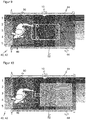
- FIG 9 shows again the passage according to Figure 8 with the configuration of monitoring fields 40 and monitoring segments 42 according to Figure 7 .
- the person 46 is carrying an object, in particular a cart 52, a pallet or the like.
- Such a carriage 52 can also be identified by evaluating the monitoring segments 42, in each of which an object is detected. For example, the four corners of the carriage 52 are suitable for this purpose. This can also be differentiated with the resolution given by the monitoring segments 42, such as a further example of another carriage 52 in FIG Figure 10 illustrated.
- the number of monitoring segments 42 can also be increased significantly by additional monitoring fields 40.
- Another possibility for improving the detection is to combine the detection of several sensors 10, for example one laser scanner each on both sides of the passage, in particular at different heights. This is particularly suitable for the case of a passage with a more complex geometry such as an L-shape, although this is also conceivable with only one laser scanner at the kink of the L-shape.
- the effective number of monitoring segments 42 compared to simultaneously monitored monitoring fields 40 is increased significantly from n + m to n * m by two groups each subdividing a coordinate. How with the Figures 5 and 6 explained, this can be increased even further by gaps or areas covered by only one group and / or a further overlap field which, with a clever design of the monitoring fields 40, halves the monitoring segments 42 again.
- the available simultaneously monitored monitoring fields 40 which are only available in limited numbers because of the evaluation effort, are optimally used for a finer resolution.
Description
Die Erfindung betrifft einen optoelektronischen Sensor und ein Verfahren zur sicheren Erfassung von Objekten in einem Überwachungsbereich nach dem Oberbegriff von Anspruch 1 beziehungsweise 14.The invention relates to an optoelectronic sensor and a method for the reliable detection of objects in a monitoring area according to the preamble of
Derartige Sensoren werden unter anderem zur Absicherung von Maschinen eingesetzt. Herkömmlich wird dazu ein Schutzfeld überwacht, das während des Betriebs der Maschine vom Bedienpersonal nicht betreten werden darf. Erkennt der Sensor einen unzulässigen Schutzfeldeingriff, etwa ein Bein einer Bedienperson, so löst er einen Nothalt der Maschine aus. In der Sicherheitstechnik eingesetzte Sensoren müssen besonders zuverlässig arbeiten und deshalb hohe Sicherheitsanforderungen erfüllen, beispielsweise die Norm EN13849 für Maschinensicherheit und die Gerätenorm EN61496 für berührungslos wirkende Schutzeinrichtungen (BWS). Zur Erfüllung dieser Sicherheitsnormen sind eine Reihe von Maßnahmen zu treffen, wie beispielsweise sichere elektronische Auswertung durch redundante, diversitäre Elektronik oder verschiedene Funktionsüberwachungen, speziell die Überwachung der Verschmutzung optischer Bauteile einschließlich einer Frontscheibe.Such sensors are used, among other things, to protect machines. Conventionally, a protective field is monitored for this, which the operating personnel must not enter while the machine is in operation. If the sensor detects an impermissible protective field intervention, for example an operator's leg, it triggers an emergency stop of the machine. Sensors used in safety technology must work particularly reliably and therefore meet high safety requirements, for example the EN13849 standard for machine safety and the EN61496 device standard for electro-sensitive protective devices (ESPE). To meet these safety standards, a number of measures must be taken, such as safe electronic evaluation through redundant, diverse electronics or various function monitoring, especially monitoring the contamination of optical components including a front window.
Eine mit der Absicherung einer Maschine verwandte Aufgabe ist eine Zugangskontrolle, welche den Personenkreis begrenzt, der sich in einem bestimmten Bereich aufhält. Dabei sind wiederum sehr unterschiedliche Sicherheitsanforderungen vorstellbar, die vom einfachen Zählen etwa an Flughäfen bis zu einer strengen Zugangsbeschränkung für ganz bestimmte Bedienpersonen reichen. Gerade für den letzteren Fall werden häufig besonders gesicherte Türen eingesetzt. Sobald jedoch die Tür unter Beachtung der Absicherungsprozedur geöffnet wurde, fehlt es an einer Kontrolle, ob tatsächlich nur eine Person hindurchtritt. Dementsprechend ist auch die Anzahl der Personen im gesicherten Bereich unbekannt.A task related to securing a machine is an access control, which limits the group of people who are in a certain area. In turn, very different security requirements are conceivable, ranging from simple counting at airports, for example, to strict access restrictions for very specific operators. Especially for the latter case, specially secured doors are often used. However, as soon as the door has been opened in compliance with the security procedure, there is no control to determine whether it actually is only one person passes through. Accordingly, the number of people in the secured area is also unknown.
Herkömmlich sind in einigen Fällen über die Zugangskontrolle hinaus weitere Maßnahmen der Absicherung vorgesehen. So wird bei einer LOTO-Prozedur (Lock out, Tag out) eine Maschine im gesicherten Bereich zusätzlich gegen unautorisiertes Einschalten gesichert. Es handelt sich aber um eine reine Organisationsmaßnahme, die auf dem Handeln des Maschinenbedieners beim Verlassen des gesicherten Bereichs basiert. Dies kann in Erweiterungen erzwungen werden, die bestimmte Prozeduren beim Verlassen des gesicherten Bereichs oder dem Wiederanlaufen der Maschine fordern. Das begrenzt die Handlungsmöglichkeiten von Personen, die unbemerkt in den gesicherten Bereich gelangt sind, verhindert aber nicht deren Anwesenheit. Eine echte Eintrittsschleuse, die nur jeweils einer Person Zugang gewährt, ist auch bekannt, aber sehr aufwändig und im Alltag umständlich, etwa ungeeignet für den Zugang mit einem Wagen.Traditionally, in some cases, additional security measures are provided in addition to access control. With a LOTO procedure (lock out, tag out), a machine in the secured area is additionally secured against unauthorized switching on. However, it is a purely organizational measure based on the actions of the machine operator when leaving the secured area. This can be enforced in extensions that require certain procedures when leaving the secure area or restarting the machine. This limits the options for people who have entered the secured area unnoticed, but does not prevent their presence. A real entry lock, which only allows one person access, is also known, but very complex and cumbersome in everyday life, for example unsuitable for access with a car.
In manchen Anwendungen ist demnach wünschenswert, genauere Informationen zu erfassen als eine bloße binäre Schutzfeldverletzung. Das gilt beispielsweise für kooperative Arbeitsplätze, an denen Mensch und Roboter eng zusammenarbeiten. Dafür eignen sich aber verfügbare sichere Sensoren nur bedingt. So ist zwar denkbar, mehrere Lichtgitter parallel zueinander zu montieren und so verschiedene Annährungspositionen oder auch deren Abfolge zu erfassen. Der Aufwand für die Montage ist hoch und im Grunde nur in einer Art Korridor nutzbar, in denen die Lichtgitter an deren seitlicher Begrenzung montiert sind. Trotzdem bleiben die so gewonnenen Zusatzinformationen begrenzt.In some applications it is therefore desirable to acquire more precise information than a mere binary protection field violation. This applies, for example, to cooperative workplaces where humans and robots work closely together. However, available safe sensors are only suitable to a limited extent. It is conceivable to mount several light grids parallel to one another and thus to record different approach positions or their sequence. The installation effort is high and can basically only be used in a type of corridor in which the light grids are installed at their lateral borders. Nevertheless, the additional information obtained in this way remains limited.
Laserscanner liefern grundsätzlich wesentlich genauere Positionsinformationen und werden bereits häufig in der Sicherheitstechnik eingesetzt. Ein derartiger Sicherheitslaserscanner ist aus der
Dabei sind zwei grundsätzliche Prinzipien bekannt, die Lichtlaufzeit zu bestimmen. Bei phasenbasierten Verfahren wird das Sendelicht moduliert und die Phasenverschiebung des empfangenen gegenüber dem gesendeten Licht ausgewertet. Bei pulsbasierten Verfahren misst der Laserscanner die Laufzeit, bis ein ausgesandter Lichtpuls wieder empfangen wird. In einem beispielsweise aus der
Die Positionsinformation in zweidimensionalen Polarkoordinaten ist aber nur intern verfügbar, und bisher gibt es keine Geräte, welche diese Informationen auf sichere Weise nach außen weitergeben. Selbst wenn zukünftig eine entsprechende sichere Ausgabe geschaffen wird, müsste dann auch die gesamte Auswertung nach außen verlagert werden, und es erfordert sehr aufwändige Programmierung außerhalb des Laserscanners, um auf diesem Weg eine Sicherheitsanwendung zu lösen, zumal diese Programmierung eine in sich sichere Auswertung gewährleisten muss.However, the position information in two-dimensional polar coordinates is only available internally, and so far there are no devices that transmit this information to the outside in a secure manner. Even if a corresponding safe output is created in the future, the entire evaluation would then have to be relocated to the outside, and it requires very complex programming outside of the laser scanner in order to solve a safety application in this way, especially since this programming must ensure an inherently safe evaluation .
Sicher ausgegeben wird dagegen die Information, ob ein Schutzfeld verletzt ist, und dieses Schutzfeld ist in bekannten Laserscannern frei konfigurierbar. Das bietet einen ganz anderen Ansatzpunkt, um Objekteingriffe zu lokalisieren, der keines sicheren Zugriffs auf die Rohdaten Abstand und Winkel bedarf und die vorhandene Erkennung von Schutzfeldverletzungen ausnutzt, statt die Auswertung komplett neu zu programmieren. Sind allerdings mehrere Schutzfelder vorgesehen, was für eine einigermaßen flexible Lokalisierung eines Objektes erforderlich ist, so wird üblicherweise zwischen diesen Schutzfeldern umgeschaltet. Die Ansprechzeit für jedes einzelne Schutzfeld ist dadurch erheblich erhöht.In contrast, the information whether a protective field is violated is reliably output, and this protective field can be freely configured in known laser scanners. This offers a completely different starting point for localizing object intrusions, which does not require reliable access to the raw data for distance and angle and uses the existing detection of protective field violations instead of completely reprogramming the evaluation. If, however, several protective fields are provided, which is necessary for a fairly flexible localization of an object, then it is customary to switch between these protective fields. This significantly increases the response time for each individual protective field.
Seit kurzem gibt es auch Laserscanner, die mehrere Schutzfelder simultan auswerten. Im Prinzip ist die Anforderung damit erfüllt, denn nun kann man den Überwachungsbereich frei in parallel überwachte Schutzfelder unterteilen und aus der Identität eines verletzten Schutzfeldes auf die momentane Position des eingreifenden Objekts schließen.Laser scanners have recently also been available that evaluate several protective fields simultaneously. In principle, this fulfills the requirement, because the monitoring area can now be freely divided into protective fields monitored in parallel and the current position of the intervening object can be deduced from the identity of an injured protective field.
Das ermöglicht nicht nur eine Lokalisierung, sondern auch eine sogenannte Sequenzüberwachung, bei der festgestellt wird, ob Schutzfelder in einer bestimmten Reihenfolge betreten werden, um so eine Bewegung nachzuvollziehen. Das wird beispielsweise genutzt, damit bei Annäherung an einen Roboter Schutzfelder in der richtigen Abfolge verletzt und anschließend wieder in umgekehrter Reihenfolge verlassen werden. Dann kann der Roboter lediglich verlangsamen, solange die Person in der Nähe ist, und danach direkt in voller Geschwindigkeit weiterarbeiten, statt wie klassisch mit einem Nothalt gestoppt zu werden, was auch einen mühsamem Wiederanlauf nach sich zöge.This not only enables localization, but also so-called sequence monitoring, in which it is determined whether protective fields are entered in a certain order in order to understand a movement. This is used, for example, so that when a robot approaches, protective fields are violated in the correct sequence and then left again in the reverse order. Then the robot can only slow down as long as the person is nearby and then continue working straight away at full speed, instead of being stopped with an emergency stop as in the classic way, which would also involve a laborious restart.
Allerdings ist die simultane Auswertung sehr rechenintensiv und daher bislang nur für maximal vier parallele Schutzfelder vorgesehen. Dabei wird jedes Schutzfeld eigenständig betrachtet und direkt mit einer Aktion in der Sicherheitslogik verknüpft, wie einer Notabschaltung oder einem Sequenzzähler, der bei einer Sequenzüberwachung eine erwartete Bewegung verfolgt. Dadurch werden die wenigen verfügbaren Schutzfelder sehr rasch ausgeschöpft. Selbst wenn sich die Anzahl parallel überwachbarer Schutzfelder in zukünftigen Gerätegenerationen erhöht, bleibt dies ein stark limitierender Faktor für die Ortauflösung einer Positionsbestimmung oder das Nachvollziehen einer Bewegung durch Sequenzüberwachung mit Schutzfeldern.However, the simultaneous evaluation is very computationally intensive and therefore only provided for a maximum of four parallel protective fields. Each protective field is viewed independently and linked directly to an action in the safety logic, such as an emergency shutdown or a sequence counter that tracks an expected movement during sequence monitoring. As a result, the few available protective fields are used up very quickly. Even if the number of protective fields that can be monitored in parallel increases in future device generations, this remains a very limiting factor for the spatial resolution of a position determination or the tracking of a movement through sequence monitoring with protective fields.
Die
Die
In der
In the
Es ist daher Aufgabe der Erfindung, die Erfassung von Objekten mit simultan überwachten Schutzfeldern zu verbessern.
Diese Aufgabe wird durch einen optoelektronischen Sensor und ein Verfahren zur sicheren Erfassung von Objekten in einem Überwachungsbereich nach Anspruch 1 beziehungsweise 14 gelöst. Der Sensor ist in der Lage, Objekte sicher zu erfassen. Dazu wird das Empfangslicht aus dem Überwachungsbereich ausgewertet, um eine erste Anzahl von Überwachungsfeldern simultan zu überwachen. Überwachungsfelder sind insbesondere frei konfigurierte Teilbereiche des Überwachungsbereichs entsprechend den einleitend erläuterten Schutzfeldern, deren Verletzung aber anders als herkömmlich nicht zwingend unmittelbar zu einer sicherheitsgerichteten Reaktion führt. Durch die simultane Überwachung wird sicher erfasst, in welchem Überwachungsfeld sich ein Objekt befindet, was klassisch als Schutzfeldverletzung bezeichnet würde. Natürlich ist der Fall eingeschlossen, dass es derzeit keine Schutzfeldverletzungen gibt, also alle Überwachungsfelder frei von Objekten sind. Dabei ist mit Objekt insbesondere ein unzulässiges Objekt gemeint, denn es ist möglich, bestimmte Objekte zu ignorieren oder auszublenden, etwa weil sie zu klein sind, nur ganz kurzzeitig auftreten, oder weil es sich um bekannte und erlaubte Objekte handelt.It is therefore the object of the invention to improve the detection of objects with simultaneously monitored protective fields.
This object is achieved by an optoelectronic sensor and a method for the reliable detection of objects in a monitoring area according to
Die Erfindung geht nun von dem Grundgedanken aus, Überwachungsfelder zumindest teilweise überlappen zu lassen. Das erscheint aus dem Blickwinkel der herkömmlichen Absicherungsfunktion zunächst sinnlos, denn dafür genügt es, wenn einmal erkannt ist, ob sich ein Objekt in einer gefährlichen Position befindet. Durch die Überlappung entsteht eine zweite Anzahl von Überlappungssegmenten, wobei die zweite Anzahl größer ist als die erste Anzahl, es also mehr und insbesondere deutlich mehr Überlappungssegmente als Überlappungsfelder gibt. Die Überlappungssegmente definieren sich darüber, welche Überlappungsfelder dort jeweils überlappen, so dass also innerhalb eines Überwachungssegments dieselben Überwachungsfelder überlappen, während sich dies zu einem anderen Überwachungssegment hinsichtlich mindestens eines Überwachungsfeldes ändert, d.h. mindestens ein Überlappungsfeld hinzukommt, wegfällt oder wechselt. Nochmals anders ausgedrückt hat jedes Überwachungssegment eine Art Fingerabdruck der dort überlappenden Überwachungsfelder, wobei man sich den Fingerabdruck beispielsweise als binären Vektor vorstellen kann. Dessen Dimension entspricht der ersten Anzahl, und seine binären Einträge enthalten jeweils eine Eins für Überwachungsfelder, die mit dem Überwachungssegment überlappt, und sonst Nullen. Mindestens ein Eintrag dieses Fingerabdrucks variiert von Überwachungssegment zu Überwachungssegment.The invention is based on the basic idea of allowing monitoring fields to at least partially overlap. From the point of view of the conventional safety function, this initially seems pointless, because it is sufficient once it has been recognized whether an object is in a dangerous position. The overlap results in a second number of overlap segments, the second number being greater than the first number, that is to say there are more and in particular significantly more overlap segments than fields of overlap. The overlap segments are defined by which overlap fields overlap there, so that the same monitoring fields overlap within a monitoring segment, while this changes to another monitoring segment with regard to at least one monitoring field, i.e. at least one overlap field is added, omitted or changed. To put it another way, each monitoring segment has a kind of fingerprint of the monitoring fields that overlap there, whereby the fingerprint can be imagined as a binary vector, for example. Its dimension corresponds to the first number, and its binary entries each contain a one for monitoring fields that overlap with the monitoring segment, and zeros otherwise. At least one entry of this fingerprint varies from monitoring segment to monitoring segment.
Die Erfassung ist sicher vorzugsweise im Sinne von Maschinensicherheit, insbesondere nach den einleitend genannten Normen. Das bedeutet aber nicht zwingend, dass der Sensor in einer Sicherheitsapplikation eingesetzt ist. Beispielsweise ist auch denkbar, dass die Konfiguration der Überwachungsfelder keine normgerechte Sicherheit bietet, oder dass die Anwendung nur auf Beobachtung oder beispielsweise Absichern im Sinne von Diebstahlsicherung, nicht Schutz vor Verletzungsgefahren zielt.The detection is safe preferably in the sense of machine safety, in particular according to the standards mentioned in the introduction. However, this does not necessarily mean that the sensor is used in a safety application. For example, it is also conceivable that the configuration of the monitoring fields does not offer standard-compliant security, or that the application is only aimed at observation or, for example, protection in the sense of theft protection, not protection against the risk of injury.
Die Erfindung hat den Vorteil, dass effektiv die Anzahl simultan überwachbarer Felder von der eigentlich hardwareseitig vorgesehenen ersten Anzahl auf die zweite Anzahl erhöht wird. Das ermöglicht eine genauere Positionsbestimmung, aber auch Informationen über eine Bewegung oder eine Objektgröße, was genutzt werden kann, um einen Roboter oder eine Maschine sicher zu verlangsamen oder einen Arbeitsschritt in einen Bereich zu verlagern, der weiter weg von dem Objekteingriff liegt und somit keine Person gefährdet. Das ist nur ein Beispiel einer Vielzahl denkbarer einfacher Lösungen für Anwendungen, die von der verbesserten Information profitieren und dabei Stillstandzeiten des Roboters oder der Maschine soweit möglich vermeiden. Dabei ist die Konfiguration und Auswertung von Überwachungsfeldern oder Überwachungssegmenten wesentlich einfacher zu handhaben und zu programmieren als eine Rohinformation beispielsweise in Form von Abstand und Winkel.The invention has the advantage that the number of fields that can be monitored simultaneously is effectively increased from the first number actually provided on the hardware side to the second number. This enables a more precise position determination, but also information about a movement or an object size, which can be used to safely slow down a robot or machine or to relocate a work step to an area that is further away from the object engagement and thus no person endangered. This is just one example of a multitude of conceivable simple solutions for applications that benefit from the improved information and avoid downtimes of the robot or machine as far as possible. The configuration and evaluation of monitoring fields or monitoring segments is much easier to handle and program than raw information, for example in the form of distance and angle.
Ein erfasstes Objekt wird anhand der Überwachungsfelder, in denen ein Objekt erkannt ist, einem Überwachungssegment zugeordnet. So kann aus den Informationen über Objekte in den gröber auflösenden Überwachungsfeldern eindeutig auf die Position entsprechend den feiner auflösenden Überwachungssegmenten geschlossen werden. Es wurde schon erläutert, dass die Überwachungssegmente durch einen Fingerabdruck definiert werden können, d.h. einen binären Vektor, der codiert, welche Überwachungsfelder dort überwachen. Entsprechend kann das Ergebnis der simultanen Auswertung von Überwachungsfeldern als binärer Vektor verstanden werden, in welchem Überwachungssegment ein Objekteingriff erfasst ist. Ein Vergleich der binären Vektoren ergibt das betroffene Überwachungssegment. Das ist selbstverständlich nur ein nicht einschränkendes Beispiel, wie die Zuordnung zu einem Überwachungssegment umsetzbar ist. Anders als bei einem klassischen Schutzfeld, dessen Verletzung sofort zu einer sicherheitsgerichteten Information führt, werden dabei Verletzungen der Überwachungsfelder in einem ersten Schritt ausgewertet, um das betroffene Überwachungssegment zu finden. Daran kann sich dann eine sicherheitsgerichtete Reaktion wie ein Abschaltsignal anschließen, wobei dann das Überwachungssegment als Schutzfeld fungiert. Ebenso sind aber auch andere Auswertungen denkbar, welche die mit verbesserter Auflösung erfasste Information über den Objekteingriff ausnutzen.A detected object is assigned to a monitoring segment based on the monitoring fields in which an object is recognized. Thus, from the information about objects in the coarser-resolution monitoring fields, conclusions can be drawn unambiguously about the position corresponding to the more finely-resolved monitoring segments. It has already been explained that the surveillance segments can be defined by a fingerprint, i.e. a binary vector that codes which monitoring fields monitor there. Accordingly, the result of the simultaneous evaluation of monitoring fields can be understood as a binary vector, in which monitoring segment an object intervention is detected. A comparison of the binary vectors shows the monitoring segment concerned. Of course, this is only a non-limiting example of how the assignment to a monitoring segment can be implemented. In contrast to a classic protective field, the violation of which immediately leads to safety-related information, violations of the monitoring fields are evaluated in a first step in order to find the monitoring segment concerned. This can then be followed by a safety-related reaction such as a switch-off signal, with the monitoring segment then functioning as a protective field. However, other evaluations are also conceivable which utilize the information about the object intervention that is recorded with improved resolution.
Vorzugsweise wird eine Sequenz von Überwachungssegmenten ausgewertet, denen ein erfasstes Objekt zugeordnet wird. Die Sequenz oder Abfolge von Überwachungssegmenten, in denen ein Objekt erfasst ist, liefert Informationen über den Weg eines Objekts insbesondere in der unmittelbaren Vergangenheit, und zwar wegen der erhöhten zweiten Anzahl von Überwachungssegmenten gegenüber der ersten Anzahl Überwachungsfelder mit feinerer Auflösung. Das ermöglicht eine Reaktion beispielsweise in Abhängigkeit von Bewegungsrichtung und Geschwindigkeit, aber auch eine Vorhersage der Bewegung einer Person in der Umgebung einer abzusichernden Gefahrenquelle und damit das Planen entsprechender Maßnahmen zu deren Absicherung, vorzugsweise eine Anpassung, die nur in seltenen Notfällen eine Abschaltung erfordert.A sequence of monitoring segments to which a detected object is assigned is preferably evaluated. The sequence or succession of monitoring segments in which an object is detected provides information about the path of an object Object in particular in the immediate past, specifically because of the increased second number of monitoring segments compared to the first number of monitoring fields with finer resolution. This enables a reaction, for example, depending on the direction of movement and speed, but also a prediction of the movement of a person in the vicinity of a source of danger to be secured and thus the planning of appropriate measures to protect it, preferably an adjustment that only requires a shutdown in rare emergencies.
Vorteilhafterweise wird eine Bewegung des Objekts überwacht. Die verfeinerte Auflösung mittels Überwachungssegmenten ermöglicht eine Objektverfolgung. Ein Anwendungsbeispiel ist die Durchgangskontrolle durch Überwachung der Bewegungen an einem Durchgang. Dabei ist ein Durchgang beispielsweise ein durch seitliche Begrenzungen geschaffener Durchgangsbereich, eine Tür oder dergleichen. Denkbar ist aber auch, den Übertritt in verschiedene Zonen eines größeren Produktions- oder sonstigen Bereichs zu überwachen. Der Sensor überwacht, wenn sich Personen von der einen Seite zu der anderen Seite des Durchgangs bewegen, und zählt diese Ereignisse vorzugsweise zugleich. Als Zusatzfunktion kann auch die Tür und deren Stellung oder Öffnungszustand überwacht werden. Meist befindet sich an einem Ende des Durchgangs ein gesicherter Bereich, obwohl das nicht zwingend der Fall sein muss. Dann ist aufgrund des erfindungsgemäßen Sensors stets bekannt, ob jemand den gesicherten Bereich betritt und vorzugsweise auch, wie viele Personen sich dort aufhalten, oder es wird ein Überblick geschaffen, wo sich Personen in einem größeren überwachten Bereich aufhalten. Auch die Erfassung von sonstigen Objekten, etwa mit Personen mitgeführte Wagen oder dergleichen, ist denkbar. Dies gelingt mit dem erfindungsgemäßen Sensor auf eine sehr einfache und kostengünstige Weise. Besondere organisatorische Maßnahmen, Zugangsprozeduren oder aufwändige Schleusen sind dafür nicht erforderlich.A movement of the object is advantageously monitored. The refined resolution by means of monitoring segments enables object tracking. An application example is the passage control by monitoring the movements at a passage. A passage is, for example, a passage area created by lateral boundaries, a door or the like. However, it is also conceivable to monitor the transition into different zones of a larger production or other area. The sensor monitors when people move from one side to the other of the passage and preferably counts these events at the same time. As an additional function, the door and its position or opening status can also be monitored. There is usually a secured area at one end of the passage, although this does not necessarily have to be the case. Because of the sensor according to the invention, it is always known whether someone is entering the secured area and preferably also how many people are there, or an overview is created of where people are in a larger monitored area. It is also conceivable to detect other objects, for example cars carried with people or the like. This is achieved in a very simple and inexpensive manner with the sensor according to the invention. Special organizational measures, access procedures or complex locks are not required for this.
Der Sensor weist bevorzugt einen sicheren Ausgang zur Ausgabe von Informationen über Objekte in Überwachungsfeldern auf. Ein herkömmlicher Sicherheitssensor liefert oft lediglich ein binäres Abschaltsignal. Nach dieser bevorzugten Ausführungsform ist vorgesehen, die Informationen auszugeben, in welchen Überwachungsfeldern Objekte erfasst wurden, vorzugsweise für alle simultan überwachten Überwachungsfelder. Eine Verletzung eines Überwachungsfeldes ist dabei erst einmal nur eine sichere Ausgabegröße, die weiter verarbeitet wird, jedoch nicht wie herkömmlich bei Schutzfeldern direkt in einer sicherheitsgerichteten Reaktion mündet. Selbstverständlich kann aber das Ergebnis weiterer Auswertungen eine solche sicherheitsgerichtete Reaktion sein.The sensor preferably has a safe output for outputting information about objects in monitoring fields. A conventional safety sensor often only supplies a binary switch-off signal. According to this preferred embodiment it is provided to output the information about the monitoring fields in which objects were detected, preferably for all monitoring fields monitored simultaneously. A violation of a monitoring field is only a safe output variable that is processed further, but not directly as is conventional with protective fields leads to a safety-related reaction. Of course, the result of further evaluations can be such a safety-related reaction.
Die Auswertungseinheit ist vorzugsweise zumindest teilweise in einer Sicherheitssteuerung implementiert, die über eine sichere Schnittstelle an den sicheren Ausgang angeschlossen ist. Dies lässt sich auch so verstehen, dass der erfindungsgemäße Sensor eine Anordnung aus dem eigentlichen Sensor und einer Erweiterung seiner Anschlüsse und Auswertungskapazität in Form der Sicherheitssteuerung ist. In einer bevorzugten Arbeitsteilung bestimmt der Sensor intern, in welchen Überwachungsfeldern sich Objekte befinden. Das schließt das eigentliche Messverfahren ein, beispielsweise eine Lichtlaufzeitmessung eines Laserscanners. Die weitere Auswertung erfolgt in der Sicherheitssteuerung anhand der ausgegebenen Informationen, beispielsweise eines binären Vektors mit jeweils einem Eintrag je Überwachungsfeld. Andere Aufteilungen sind aber auch denkbar, etwa dass auch noch die feinere Auswertung, in welchen Überwachungssegmenten sich Objekte befinden, intern erfolgt. Alternativ zu einer geteilten Auswertung mit einer Sicherheitssteuerung ist auch eine rein interne Auswertung vorstellbar.The evaluation unit is preferably implemented at least partially in a safety controller that is connected to the safe output via a safe interface. This can also be understood to mean that the sensor according to the invention is an arrangement of the actual sensor and an extension of its connections and evaluation capacity in the form of the safety controller. In a preferred division of labor, the sensor determines internally in which monitoring fields there are objects. This includes the actual measuring process, for example a time-of-flight measurement of a laser scanner. Further evaluation is carried out in the safety control based on the information output, for example a binary vector with one entry for each monitoring field. However, other subdivisions are also conceivable, for example that the finer evaluation of the monitoring segments in which objects are also carried out internally. As an alternative to a split evaluation with a safety controller, a purely internal evaluation is also conceivable.
Der Sensor ist vorzugsweise als Laserscanner mit einem Lichtsender zum Aussenden eines Lichtsignals und einer Ablenkeinheit zum periodischen Ablenken des Lichtsignals in dem Überwachungsbereich ausgebildet. Das ist ein in der Sicherheitstechnik häufig eingesetzter Sensor mit großem Überwachungsbereich, der flexibel in Überwachungsfelder und auch Überwachungssegmente unterteilbar ist. Es kommen Laserscanner jeder bekannten Bauart in Betracht, insbesondere solche mit einer Ablenkeinheit in Form eines Drehspiegels oder eines rotierenden Abtastkopfes. Die Auswertungseinheit ist vorzugsweise für eine Abstandsmessung mit einem Lichtlaufzeitverfahren ausgebildet, wobei auch hier alle bekannten Möglichkeiten wie ein Puls-, ein Phasen- oder ein Pulsmittelungsverfahren in Betracht kommen. Statt eines Laserscanners ist als erfindungsgemäßer Sensor auch eine Kamera, insbesondere eine 3D-Kamera, und in Grenzen auch ein Lichtgitter denkbar, besonders wenn es als tastendes Lichtgitter mit einer Entfernungsmessung entsprechende Freiheitsgrade bietet, um Überwachungsfelder zu definieren.The sensor is preferably designed as a laser scanner with a light transmitter for emitting a light signal and a deflection unit for periodically deflecting the light signal in the monitoring area. This is a sensor that is often used in security technology and has a large monitoring area that can be flexibly subdivided into monitoring fields and monitoring segments. Laser scanners of any known type come into consideration, in particular those with a deflection unit in the form of a rotating mirror or a rotating scanning head. The evaluation unit is preferably designed for a distance measurement with a time-of-flight method, with all known possibilities such as a pulse, a phase or a pulse averaging method also coming into consideration here. Instead of a laser scanner, a camera, in particular a 3D camera, and within certain limits also a light grid are conceivable as the sensor according to the invention, especially if it offers appropriate degrees of freedom as a scanning light grid with a distance measurement to define monitoring fields.
Der Überwachungsbereich ist bevorzugt durch zwei Koordinaten beschrieben, wobei eine erste Gruppe von Überwachungsfeldern den Überwachungsbereich bezüglich der ersten Koordinate und eine zweite Gruppe von Überwachungsfeldern bezüglich der zweiten Koordinate unterteilt. Die Überwachungsfelder weisen dabei eine Geometrie auf, die dazu führt, dass jeweils eine Gruppe den Überwachungsbereich in der zugeordneten Koordinate überdeckt. Lücken sind aber denkbar und werden später noch diskutiert. In der anderen Koordinate haben die Überwachungsfelder vorzugsweise untereinander gleiche Eigenschaften. Die derart gewählten Gruppen von Überwachungsfeldern führen dazu, dass mit einer ersten Gruppe von n Überwachungsfeldern und einer zweiten Gruppe von m Überwachungsfeldern, also einer ersten Anzahl n+m, insgesamt eine zweite Anzahl von bis zu n*m Überwachungssegmenten unterschieden werden können, je nach konkreter Ausgestaltung mit Lücken auch noch einige mehr. Mit Überwachungsbereich ist dabei wie stets nicht zwingend der maximale Sichtbereich gemeint, sondern möglicherweise ein darin gewählter relevanter Teilbereich.The monitoring area is preferably described by two coordinates, a first group of monitoring fields the monitoring area with respect to the first coordinate and a second group of monitoring fields with respect to the second coordinate. The monitoring fields have a geometry that means that one group each covers the monitoring area in the assigned coordinate. However, gaps are conceivable and will be discussed later. In the other coordinate, the monitoring fields preferably have the same properties as one another. The groups of monitoring fields selected in this way mean that with a first group of n monitoring fields and a second group of m monitoring fields, i.e. a first number n + m, a total of a second number of up to n * m monitoring segments can be distinguished, depending on concrete design with gaps and a few more. As always, the monitoring area does not necessarily mean the maximum viewing area, but rather a relevant sub-area selected within it.
Vorzugsweise weist die erste Gruppe Streifen oder Rechtecke längs der ersten Koordinate und die zweite Gruppe Streifen oder Rechtecke längs der zweiten Koordinate auf. Die Streifen oder Rechtecke stehen vorzugsweise senkrecht zueinander, so dass sich ein Karomuster bildet, dessen Kästchen die Überwachungssegmente sind, aber quer in anderem Winkel stehende Streifen mit entsprechend verzerrten Kästchen sind ebenfalls möglich.The first group preferably has strips or rectangles along the first coordinate and the second group has strips or rectangles along the second coordinate. The stripes or rectangles are preferably perpendicular to one another, so that a check pattern is formed, the boxes of which are the monitoring segments, but stripes at a different angle with correspondingly distorted boxes are also possible.
Vorteilhafterweise weist die erste Gruppe Kreise oder Kreisringe und die zweite Gruppe Kreissektoren auf. Die Kreise beziehungsweise Kreisringe unterteilen eine radiale Koordinate, die Kreissektoren oder umgangssprachlich Tortenstücke eine Winkelkoordinate. Damit sind diese Überwachungsfelder gleichsam an die natürlichen Polarkoordinaten eines Laserscanners angepasst, wobei aber einleitend erläutert wurde, dass die Scandaten selbst außen nicht verfügbar sind, und dass, selbst wenn künftige Laserscanner diese Informationen sicher bereitstellen, deren sichere direkte Auswertung ohne Ausnutzen der etablierten Schutzfeldüberwachung ausgesprochen aufwändig wäre. Die Kreisringe umfassen häufig nicht 360°, weil der Sichtwinkel verfügbarer sicherer Laserscanner eher nur etwas mehr als 180° beträgt. Genaugenommen kann es sich also auch bei den Kreisen oder Kreisringen der ersten Gruppe nur um Kreissektoren handeln, die sich aber im Gegensatz zu den Überwachungsfeldern der zweiten Gruppe die Winkelkoordinate nicht aufteilen. Vielmehr überdecken die Kreisringe schon einzeln, bis auf die noch zu erläuternden möglichen Lücken, den relevanten Sichtwinkelbereich.The first group advantageously has circles or circular rings and the second group has circular sectors. The circles or circular rings subdivide a radial coordinate, the circular sectors or slices of pie an angular coordinate. This means that these monitoring fields are, as it were, adapted to the natural polar coordinates of a laser scanner, although it was explained in the introduction that the scan data itself is not available externally and that even if future laser scanners reliably provide this information, their safe direct evaluation is pronounced without using the established protective field monitoring would be laborious. The circular rings often do not encompass 360 ° because the viewing angle of available safe laser scanners is only slightly more than 180 °. Strictly speaking, the circles or circular rings of the first group can only be sectors of a circle which, in contrast to the monitoring fields of the second group, do not divide the angular coordinates. Rather, the circular rings individually cover the relevant viewing angle range, with the exception of the possible gaps still to be explained.
Die Überwachungsfelder einer Gruppe grenzen bevorzugt jeweils unmittelbar aneinander. Diese Unterteilung ist besonders eingängig. Als ein Beispiel liegen Überwachungsfelder jeweils direkt nebeneinander. In einem weiteren von zahlreichen Beispielen kann das jeweils i-te Überwachungsfeld vollständig von dem i+1-ten Überwachungsfeld überdeckt sein, welches jeweils noch einen nicht überlappenden Rand hinzufügt. Damit sind dieselben Überwachungssegmente unterscheidbar, es müssen lediglich andere Fingerabdrücke ausgewertet werden. Für die Sicherheitstechnik hat die Unterscheidung noch eine besondere Bedeutung, denn unter Umständen ist nur das zweite Beispiel zulässig. Es gibt nämlich in einigen Normen die Forderung, dass sich ein Schutzfeld nur unmittelbar an die Beobachtungsquelle anschließen darf, jedes Schutzfeld also auch die Sichtlinie zum Sensor enthalten muss. Ansonsten könnten Abschattungen aus nicht überwachten Bereichen zu Fehlern führen. Das lässt sich umgehen, indem der Schatten eines jeden Objekts als Objekt gewertet wird. Außerdem ist erfindungsgemäß in den meisten Fällen jeder Punkt von mehreren Schutzfeldern überwacht, so dass es genügt, wenn eines davon die Sichtlinienbedingung erfüllt. Schließlich ist die Erfindung auch nicht auf Anwendungen begrenzt, in denen diese Forderung gilt.The monitoring fields of a group are preferably each directly adjacent to one another. This subdivision is particularly intuitive. As an example, monitoring fields are located directly next to each other. In another of numerous examples, the i-th monitoring field in each case can be completely covered by the i + 1-th monitoring field, which in each case still adds a non-overlapping edge. This means that the same monitoring segments can be distinguished; only other fingerprints have to be evaluated. The distinction is of particular importance for safety technology, because under certain circumstances only the second example is permitted. In fact, in some standards there is a requirement that a protective field may only be directly connected to the observation source, i.e. that each protective field must also contain the line of sight to the sensor. Otherwise, shadows from areas that are not monitored could lead to errors. This can be avoided by treating the shadow of each object as an object. In addition, according to the invention, in most cases each point is monitored by a plurality of protective fields, so that it is sufficient if one of them meets the line-of-sight condition. Finally, the invention is not limited to applications in which this requirement applies.
Bevorzugt unterteilen die Überwachungsfelder der ersten Gruppe den Überwachungsbereich bezüglich der ersten Koordinate und/oder die Überwachungsfelder der zweiten Gruppe den Überwachungsbereich bezüglich der zweiten Koordinate nur bis auf mindestens eine Lücke. Diese mehrfach angesprochene Lücke ist sozusagen ein zusätzliches passives Überwachungsfeld und erhöht ohne Mehraufwand die Anzahl möglicher Überwachungssegmente. Dafür wird die Information genutzt, dass keines der Überwachungsfelder einer Gruppe anspricht und folglich das Objekt sich in der Lücke befinden muss. Das setzt natürlich voraus, dass nur entweder Überwachungsfelder der ersten Gruppe oder der zweiten Gruppe an derselben Position eine Lücke aufweisen, ansonsten wird es eine echte Lücke, in der gar nicht überwacht wird.The monitoring fields of the first group preferably subdivide the monitoring area with regard to the first coordinate and / or the monitoring fields of the second group subdivide the monitoring area with regard to the second coordinate only up to at least one gap. This gap, mentioned several times, is, so to speak, an additional passive monitoring field and increases the number of possible monitoring segments without additional effort. For this purpose, the information is used that none of the monitoring fields of a group is responding and consequently the object must be in the gap. This of course presupposes that only monitoring fields of the first group or the second group have a gap in the same position, otherwise it becomes a real gap in which there is no monitoring at all.
Vorzugsweise ist zusätzlich zu den Überwachungsfeldern der beiden Gruppen ein weiteres Überwachungsfeld vorgesehen, welches die Hälfte des Überwachungsbereichs abdeckt. Damit kann bei geschickter Auslegung der Überwachungsfelder die zweite Anzahl verdoppelt werden, indem Überwachungssegmente geteilt und die Teilüberwachungssegmente danach unterschieden werden, ob sie mit dem weiteren Überwachungsfeld überlappen oder nicht. Die Hälfte muss nur ungefähr genau erreicht sein, erst eine deutliche Abweichung führt dazu, dass der Vorteil signifikant geringer wird als eine Verdopplung. Außerdem bezieht sich die Hälfte nicht unbedingt auf die Fläche des Überwachungsbereichs, sondern vorzugsweise auf eine der beiden Koordinaten. Das weitere Überwachungsfeld umfasst also beispielsweise ungefähr den halben zu überwachenden Radius oder ungefähr den halben relevanten Sichtwinkel.In addition to the monitoring fields of the two groups, a further monitoring field is preferably provided which covers half of the monitoring area. With a clever design of the monitoring fields, the second number can thus be doubled by dividing monitoring segments and distinguishing the partial monitoring segments according to whether or not they overlap with the further monitoring field. Half only needs to be reached approximately exactly; only a significant deviation leads to the advantage being significantly less than doubling. In addition, half does not necessarily relate to the area of the Monitoring area, but preferably to one of the two coordinates. The further monitoring field thus includes, for example, approximately half the radius to be monitored or approximately half the relevant viewing angle.
Vorzugsweise liegen Überwachungsfelder einer Gruppe geschachtelt übereinander, so dass ein inneres Überwachungsfeld jeweils vollständig mit einem nächsten Überwachungsfeld überlappt und das nächste Überwachungsfeld an beiden Rändern bezüglich der zugeordneten Koordinate übersteht. Die geschachtelte Anordnung ist ein Beispiel für eine Auslegung von Überwachungsfeldern, bei denen mit dem im vorigen Absatz diskutierten weiteren Überwachungsfeld eine Verdopplung der Überwachungssegmente möglich ist.Monitoring fields of a group are preferably nested one above the other, so that an inner monitoring field in each case completely overlaps with a next monitoring field and the next monitoring field protrudes at both edges with respect to the assigned coordinate. The nested arrangement is an example of a design of monitoring fields in which a doubling of the monitoring segments is possible with the additional monitoring field discussed in the previous paragraph.
Das erfindungsgemäße Verfahren kann auf ähnliche Weise weitergebildet werden und zeigt dabei ähnliche Vorteile. Derartige vorteilhafte Merkmale sind beispielhaft, aber nicht abschließend in den sich an die unabhängigen Ansprüche anschließenden Unteransprüchen beschrieben.The method according to the invention can be developed in a similar way and shows similar advantages. Advantageous features of this type are described by way of example, but not conclusively, in the subclaims that follow the independent claims.
Die Erfindung wird nachstehend auch hinsichtlich weiterer Merkmale und Vorteile beispielhaft anhand von Ausführungsformen und unter Bezug auf die beigefügte Zeichnung näher erläutert. Die Abbildungen der Zeichnung zeigen in:
- Fig. 1
- eine schematische Schnittdarstellung eines Laserscanners;
- Fig. 2
- eine schematische Darstellung eines Laserscanners, der für eine erweiterte Auswertung an eine Sicherheitssteuerung angeschlossen ist;
- Fig.3
- eine beispielhafte Darstellung von überlappenden Überwachungsfeldern in zwei Gruppen für Radius und Winkel;
- Fig. 4
- eine beispielhafte Darstellung von überlappenden Überwachungsfeldern in zwei Gruppen für eine vertikale und eine horizontale Richtung;
- Fig. 5
- eine beispielhafte Darstellung von überlappenden Schutzfeldern ähnlich
Figur 3 , jedoch zusätzlich mit Lücken ohne Schutzfelder sowie einem zusätzlichen Schutzfeld, das effektiv die Anzahl von unterscheidbaren Überwachungssegmenten verdoppelt; - Fig. 6
- eine beispielhafte Darstellung von überlappenden Schutzfeldern ähnlich
Figur 3 , jedoch ohne Lücken und mit effektiver Verdopplung der unterscheidbaren Überwachungssegmente in radialer Richtung statt in Winkelrichtung; - Fig. 7
- eine beispielhafte Darstellung von überlappenden Schutzfeldern in zwei Gruppen für eine vertikale und eine horizontale Richtung ähnlich
Figur 4 , jedoch analog zuFigur 5 - Fig. 8
- eine Darstellung der überlappenden Schutzfelder gemäß
Figur 7 in einem Durchgang mit zwei Personen und deren Wegen; - Fig. 9
- eine Darstellung der überlappenden Schutzfelder gemäß
Figur 7 in einem Durchgang mit einer Person, die einen Wagen mitführt; und - Fig. 10
- eine Darstellung wie
Figur 9 , jedoch mit einer anderen Geometrie des Wagens.
- Fig. 1
- a schematic sectional view of a laser scanner;
- Fig. 2
- a schematic representation of a laser scanner which is connected to a safety control for an extended evaluation;
- Fig. 3
- an exemplary representation of overlapping monitoring fields in two groups for radius and angle;
- Fig. 4
- an exemplary representation of overlapping monitoring fields in two groups for a vertical and a horizontal direction;
- Fig. 5
- an exemplary representation of overlapping protective fields similar
Figure 3 , but also with gaps without protective fields and an additional protective field that effectively doubles the number of distinguishable monitoring segments; - Fig. 6
- an exemplary representation of overlapping protective fields similar
Figure 3 , but without gaps and with effective doubling of the distinguishable monitoring segments in the radial direction instead of in the angular direction; - Fig. 7
- an exemplary representation of overlapping protective fields in two groups for a vertical and a horizontal direction similar
Figure 4 , but analogous toFigure 5 additionally with gaps without protective fields and an additional protective field that effectively doubles the number of distinguishable monitoring segments; - Fig. 8
- a representation of the overlapping protective fields according to
Figure 7 in one pass with two people and their paths; - Fig. 9
- a representation of the overlapping protective fields according to
Figure 7 in one pass with a person carrying a car; and - Fig. 10
- a representation like
Figure 9 , but with a different geometry of the car.
Die Erfindung betrifft eine verbesserte Objekterfassung mit einem sicheren optoelektronischen Sensor. Sie wird nachfolgend an konkreten Ausführungsformen mit einem sicheren Laserscanner beschrieben. Das soll aber nicht einschränkend verstanden werden, denn auch andere optoelektronische Sensoren sind in der Lage, Schutz- oder Überwachungsfelder zu definieren und darin Objekte sicher zu erfassen. Erneut ohne Einschränkung seien Kameras, insbesondere 3D-Kameras etwa nach dem Lichtlaufzeit- oder Stereoprinzip und in Grenzen auch Lichtgitter genannt. Letztere lassen vor allem dann hinreichend flexible Schutzfeldkonfigurationen zu, wenn sie tastend ausgebildet sind, also nicht nur Strahlunterbrechungen detektieren, sondern auch die Entfernung bis zu dem unterbrechenden Objekt messen.The invention relates to an improved object detection with a safe optoelectronic sensor. It is described below using specific embodiments with a safe laser scanner. However, this should not be understood in a limiting sense, because other optoelectronic sensors are also able to define protective or monitoring fields and safely detect objects in them. Once again, without limitation, cameras, in particular 3D cameras, for example based on the time-of-flight or stereo principle and, within limits, also light grids are mentioned. The latter allow sufficiently flexible protective field configurations if they are designed to be probing, i.e. not only detect beam interruptions, but also measure the distance to the interrupting object.
Die Ablenkeinheit 16b ist hier als Drehspiegel ausgestaltet, die durch Antrieb eines Motors 26 kontinuierlich rotiert. Der von dem Lichtsender 12 erzeugte Lichtstrahl 14 überstreicht somit den durch die Rotationsbewegung erzeugten Überwachungsbereich 18. Abweichend von
Die jeweilige Winkelstellung der Ablenkeinheit 16b wird über einen Encoder 28 erfasst. Wird ein von dem Lichtempfänger 24 empfangenes reflektiertes Lichtsignal 20 aus dem Überwachungsbereich 18 empfangen, so kann aus der Winkelstellung der Ablenkeinheit 16b mittels des Encoders 28 auf die Winkellage des Objektes in dem Überwachungsbereich 18 geschlossen werden.The respective angular position of the
Zusätzlich wird die Laufzeit der einzelnen Laserlichtpulse von ihrem Aussenden bis zu dem Empfang nach Reflexion an dem Objekt in dem Überwachungsbereich 18 ermittelt beziehungsweise die Phasenverschiebung zwischen ausgesandtem und empfangenem Licht bestimmt. Aus der daraus resultierenden Lichtlaufzeit wird unter Verwendung der Lichtgeschwindigkeit auf die Entfernung des Objektes von dem Laserscanner 10 geschlossen. Diese Auswertung erfolgt in einer Auswertungseinheit 30, die dafür mit dem Lichtsender 12, dem Lichtempfänger 24, dem Motor 26 und dem Encoder 28 verbunden ist. Es stehen nun über den Winkel und die Entfernung zweidimensionale Polarkoordinaten aller Objekte in dem Überwachungsbereich 18 zur Verfügung. Alle genannten Funktionskomponenten sind in einem Gehäuse 32 angeordnet, das im Bereich des Lichtaus- und Lichteintritts eine Frontscheibe 34 aufweist.In addition, the transit time of the individual laser light pulses from their transmission to reception after reflection on the object in the
Die Auswertungseinheit 30 ist in der Lage, die Position der erfassten Objekte mit Überwachungsfeldern zu vergleichen, also Teilbereichen des Überwachungsbereichs 18, deren Geometrie der Auswertungseinheit 30 durch entsprechende Parameter vorgegeben oder konfiguriert ist. Damit erkennt die Auswertungseinheit 30, ob sich ein unzulässiges Objekt in dem jeweiligen Überwachungsfeld befindet. Die Überwachungsfelder werden simultan überwacht, wobei simultan hier als Gegenbegriff zu herkömmlich üblichen umschaltbaren Schutzfeldern zu verstehen ist. Die Auswertung der Objektposition bezüglich der Überwachungsfelder kann dafür parallel durchgeführt werden, aber es genügt, wenn auch ohne oder nur mit teilweiser paralleler Auswertung das Ergebnis innerhalb der Ansprechzeit des Laserscanners vorliegt.The
In einem herkömmlichen Laserscanner wäre für das Überwachungsfeld der Begriff Schutzfeld üblich. Wird ein Objekt in einem Schutzfeld erkannt, oder das Schutzfeld verletzt, so erfolgt eine sicherheitsgerichtete Abschaltung (OSSD, Output Signal Switching Device). Dadurch wird beispielsweise ein Nothalt einer angeschlossenen und von dem Laserscanner 10 überwachten Maschine ausgelöst oder ein Fahrzeug abgebremst, auf dem der Laserscanner 10 montiert ist.In a conventional laser scanner, the term protective field would be common for the monitoring field. If an object is detected in a protective field, or if the protective field is violated, a safety-related shutdown (OSSD, Output Signal Switching Device) takes place. As a result, for example, an emergency stop of a machine connected and monitored by the
Die erfindungsgemäße sichere Auswertung der Überwachungsfelder als solche kann die gleiche sein wie bei einem Schutzfeld. Im Gegensatz zu einer herkömmlichen Schutzfeldverletzung führt aber die Detektion eines Objekts in einem Überwachungsfeld noch nicht unmittelbar zu einer sicherheitsgerichteten Reaktion, obwohl denkbar ist, zumindest einige der Überwachungsfelder auch in diesem Sinne als Schutzfeld zu konfigurieren. Vorzugsweise wird jedoch der Objekteingriff anhand von Überwachungsfeldern, in denen ein Objekt erfasst wurde, noch genauer lokalisiert und analysiert. Das Endergebnis kann dann wiederum eine sicherheitsgerichtete Reaktion sein, aber es ist auch denkbar, vorerst nur Informationen zu sammeln, etwa über Position, Bewegung, Bewegungsrichtung oder Geschwindigkeit eines Objekts.The safe evaluation according to the invention of the monitoring fields as such can be the same as for a protective field. In contrast to a conventional protection field violation, however, the detection of an object in a monitoring field does not yet immediately lead to a safety-related reaction, although it is conceivable to configure at least some of the monitoring fields as a protection field in this sense as well. However, the object intervention is preferably localized and analyzed even more precisely based on monitoring fields in which an object was detected. The end result can then again be a safety-related reaction, but it is also conceivable to initially only collect information, for example about the position, movement, direction of movement or speed of an object.
Die weiteren Auswertungen von Überwachungsfeldern, die später unter Bezugnahme auf die
Eine linke erste Gruppe umfasst mehrere konzentrische kreis- oder ringförmige Überwachungsfelder 40, die mit 1...4 durchnummeriert sind. Der nicht gezeigte Laserscanner 10 bildet das Zentrum. Die Kreise oder Ringe teilen den verfügbaren Radius von Zentrum bis zur sicheren Reichweite auf. Sie sind nicht vollständig, weil ein sicherer Laserscanner 10 üblicherweise nicht für eine 360°-Überwachung ausgelegt ist, obwohl das auch nicht prinzipiell ausgeschlossen ist. Der dargestellte Winkel ist nur ein Beispiel, Winkel in der Größenordnung von 270° und mehr sind auch mit verfügbaren Geräten erreichbar. Die Anzahl und Breite der Kreise oder Ringe sind nur beispielhaft, insbesondere sind auch Ringe mit unterschiedlicher Dicke denkbar.A left first group comprises several concentric circular or ring-shaped monitoring fields 40, which are numbered 1 ... 4. The
Man kann die Darstellung der kreis- oder ringförmigen Überwachungsfelder 1...4 in
Eine mittlere zweite Gruppe weist mehrere Überwachungsfelder in Form von Kreissektoren oder Tortenstücken auf, die mit A...D bezeichnet sind. Die Kreissektoren teilen den überwachten Sichtwinkel auf. Erneut sind Anzahl und Breite nur beispielhaft, und insbesondere ist eine ungleichmäßige Aufteilung des Winkels mit verschieden großen Kreissektoren möglich.A middle, second group has several monitoring fields in the form of sectors of a circle or pie pieces, which are designated A ... D. The circular sectors divide the monitored viewing angle. Again, the number and width are only exemplary and, in particular, an uneven division of the angle with circular sectors of different sizes is possible.
Die Überwachungsfelder 40 in Form von Kreisringen einerseits und von Kreissektoren andererseits decken jeweils den Überwachungsbereich 18 ab, es gibt also einen hier sogar vollständigen Überlapp. In der rechts dargestellten Überlagerung wird also jeder Ort des Überwachungsbereichs 18 doppelt überwacht, nämlich einmal mit einem Kreisring und einmal mit einem Kreissektor. Es entsteht eine Vielzahl von Überwachungssegmenten 42, die sich jeweils dadurch definieren, welcher Kreis oder Kreisring und welcher Kreissektor einander dort überlappen. Ein Überwachungssegment 3C ist als Beispiel hervorgehoben, wo sich der Kreisring 3 und der Kreissektor C überlappen. Wenn die den Radius unterteilende Gruppe links nicht durch Kreisringe, sondern konzentrische Kreise wachsenden Radius' definiert ist, kann der Kreisring 3 ebenso identifiziert werden, nämlich dadurch, dass die Kreise 3 und 4 das Objekt erfassen und die Kreise 1 und 2 nicht. Im Unterschied dazu würde im Kreisring 4 nur noch der Kreis 4 reagieren.The monitoring fields 40 in the form of circular rings on the one hand and circular sectors on the other hand each cover the
Die Auswertungseinheit 30 des Laserscanners 10 überwacht simultan die acht Überwachungsfelder 40, nämlich die vier Kreisringe 1..4 und die vier Kreissektoren A...D. Dabei führt nun nicht direkt eine Objekterfassung in einem Überwachungsfeld 40 zu einer sicherheitsgerichteten Reaktion. Stattdessen nutzt die Auswertungseinheit 30 selbst oder eine externe Auswertung wie die Sicherheitssteuerung 38 die Information, in welchen Überwachungsfeldern 40 ein Objekt erfasst ist, um das betroffene Überwachungssegment 42 zu finden. Im Beispiel des Überwachungssegments 3C würde ein Objekt sowohl in dem Kreisring 3 als auch dem Kreissektor C erfasst. Es entsteht dadurch eine wesentlich höhere Anzahl von sechzehn effektiv überwachten Überwachungssegmenten 42 im Vergleich zu den ursprünglich nur acht simultan ausgewerteten Überwachungsfeldern 40. Auf Basis dieser genaueren Information über den Objekteingriff wird dann die zu ergreifende Maßnahme bestimmt, nämlich ob eine Bewegung (weiter)verfolgt, eine überwachte Maschine verlangsamt oder zu nicht gefährlichen Arbeitsschritten in ausreichendem Abstand zu dem Objekteingriff veranlasst wird oder ob eine sicherheitsgerichtete Abschaltung erforderlich ist.The
Mit zusätzlichen simultan überwachten Überwachungsfeldern 40 lässt sich die Anzahl von Überwachungssegmenten 42 und damit die Auflösung der Orts-, Größen- oder Bewegungsinformation überproportional weiter steigern. So sind mit je acht Kreisringen und Kreissektoren bereits 8*8=64 Überwachungssegmente 42 möglich. Allgemein entstehen durch Aufteilung in zwei Gruppen der Größen n und m, die für jeweils eine Koordinate zuständig sind wie in
Es sei nebenbei bemerkt, dass die simultane Überwachung durch einen Laserscanner 10 nicht ganz unabhängig ist. Wenn ein Objekt in einem nahen Überwachungsfeld 40 erfasst wird, ist aufgrund der Abschattung über dahinter gelegene Überwachungsfelder 42 keine zuverlässige Aussage möglich. Man kann solche Überwachungsfelder 40 vorsichtshalber auch als verletzt ansehen. Jedenfalls sollte die Abschattung in dem Absicherungskonzept berücksichtigt werden.It should be noted by the way that the simultaneous monitoring by a
Die Geometrie der Überwachungsfelder 40 gemäß
Somit illustriert die
In den gezeigten Beispielen ist die Unterteilung vollständig und regelmäßig. Es gibt also keinen Bereich der jeweils einer Gruppe zugeordneten Koordinate, der nicht durch mindestens ein Überwachungsfeld 40 abgedeckt ist, und die Überwachungsfelder 40 sind, gemessen an ihrer Koordinate, gleich groß. Der innerste Kreis oder Kreisring 1 ist eine Ausnahme, da er einen größeren Radiusbereich überdeckt als die anderen Kreisringe 2..4. Eine weitere Eigenschaft in den Beispielen der
Vollständigkeit oder Regelmäßigkeit der Unterteilung sind nicht erforderlich. Eine unregelmäßige Aufteilung, wie schon im Beispiel des innersten Kreisrings 1 in
In der Mitte links werden Kreissektoren a..c dargestellt. Im Unterschied zu
Schließlich kommt zu den beiden Gruppen von Überwachungsfeldern 40 in der Mitte rechts noch ein weiteres Überwachungsfeld LH hinzu, welches die gesamte Reichweite und den halben Sichtwinkel, folglich insgesamt den halben Überwachungsbereich 18 abdeckt.Finally, a further monitoring field LH is added to the two groups of monitoring
Diese Konfiguration kommt mit vier Kreisen oder Kreisringen, i..iv, drei Kreissektoren a..c und einem weiteren Überwachungsfeld LH, also insgesamt acht Überwachungsfeldern 40 aus. Wie die Überlagerung auf der rechten Seite der
Diese Erhöhung hat mehrere Gründe. Zum einen ist effektiv jeweils ein nicht überwachter fünfter Kreis oder Kreisring und ein nicht überwachter vierter Kreissektor hinzugekommen. Außerdem werden die Überwachungssegmente 42 nochmals durch das weitere Überwachungsfeld LH halbiert, was durch die geschickte Wahl der ineinander geschachtelten Kreissektoren a..c möglich ist.There are several reasons for this increase. On the one hand, an unsupervised fifth circle or circular ring and an unsupervised fourth circle sector have effectively been added. In addition, the
Die Funktionsweise wird am besten anhand der Erkennung eines Objekts in konkreten Überwachungssegmenten 42 verständlich. Für die Überwachungssegmente 1B..4G unterscheidet sich das Vorgehen kaum von
In den Überwachungssegmenten A1..A4 und H1..H4 wird ein Objekt nur durch die Kreise oder Kreisringe i...iv erfasst. Das gleichzeitige Ausbleiben einer Detektion in den Kreissektoren a..c, die hier eine Lücke aufweisen, liefert effektiv die gleiche Information, als gäbe es hier einen weiteren Kreissektor. Wiederum unterscheidet das weitere Überwachungsfeld LH die Gruppen A und H voneinander.In the monitoring segments A1..A4 and H1..H4 an object is only detected by the circles or circular rings i ... iv. The simultaneous failure of a detection in the circle sectors a..c, which have a gap here, effectively provides the same information, as if there was another sector here. Again, the further monitoring field LH distinguishes groups A and H from one another.
Analog wird in den Überwachungssegmenten 5A..5H des nicht aktiv überwachten Kreisrings 5 ein Objekt nur in den jeweiligen Kreissektoren a..c erfasst, und das Ausbleiben einer Information von einem der Kreise oder Kreisringe i..iv lässt darauf schließen, dass sich das Objekt in dem Kreisring 5 befinden muss. Wiederum differenziert das weitere Überwachungsfeld LH zwischen 5A..5D einerseits und 5E..5H andererseits. Eine Besonderheit sind die Überwachungssegmente 5A und 5H. Hier haben sowohl die Kreisringe i..iv als auch die Kreissektoren a..c eine Lücke. Bei dem Überwachungssegment 5A kann das noch aufgefangen werden, weil hier das weitere Überwachungsfeld LH eine sichere Objektdetektion garantiert. Ein Objekt, das ausschließlich von dem weiteren Überwachungsfeld detektiert wird, lässt sich so in dem Überwachungssegment 5A lokalisieren. In dem Überwachungssegment 5H dagegen überlappen nur noch Lücken. Es kann nicht unterschieden werden, ob gar kein Objekt vorhanden ist oder ob es sich in dem Überwachungssegment 5H befindet. Deshalb ist dieses Überwachungssegment 5H tatsächlich nicht verfügbar und mit einem X markiert, womit sich auch die Gesamtzahl von (4+1)*(3+1)*2-1=39 Überwachungssegmenten 42 erklärt.Similarly, in the monitoring segments 5A..5H of the not actively monitored
Wie durch gleichartige Schraffur und Nummerierung angedeutet, ist auf der linken Seite der
Die Kreissektoren a..d der
Wie rechts in
Man kann demnach die
Wenn sich Personen 46a-b in dem Durchgangsbereich aufhalten, so lässt sich mit den Überwachungssegmenten 42 nicht nur deren aktuelle Position bestimmen, sondern auch ihr Weg verfolgen, wie durch Fußabdrücke 48a-b angedeutet. Dazu wird die Sequenz von Überwachungssegmenten 42 ausgewertet, in denen ein Objekteingriff erkannt wurde. Damit ist auch unterscheidbar, ob es sich um eine oder wie in
Die Überwachungsfelder 40 können beispielsweise auf Höhe der Beine, Waden oder Füße einer Person angeordnet werden. Jeder Schritt verletzt eines oder mehrere Überwachungssegmente 42. Dabei zeigen Schritte ein bestimmtes Muster, etwa dass ein Schritt kurz nach dem anderen zu erwarten ist, und zwar nur wenige Überwachungssegmente 42 weiter in horizontaler und alternierend etwas näher an und etwas weiter weg von dem Sensor 10 in vertikaler Richtung. Dabei ist zu beachten, dass ein Objekt in einem Überwachungssegment 42 näher an dem Sensor 10 die dahinterliegenden Überwachungssegmente 42 abschattet. Das ist aber nicht kritisch, weil im Verlauf der Bewegung jede Person 46a-b sich erst an den Sensor 10 annähert und sich dann wieder entfernt. Diese unterschiedlichen Perspektiven des Sensors 10 auf die Personen 46a-b erlauben dennoch eine Erfassung jeder einzelnen Person 46a-b. Möglicherweise scheitert der Sensor 10 bei nur relativ wenigen Überwachungssegmenten 42 noch an einer sicheren Unterscheidung von dicht hintereinander gehenden Personen 46a-b. Dann wird aber zumindest erkannt, dass es nicht nur eine Person 46a-b ist, und es erfolgt eine Fehlermeldung beispielsweise mit der Aufforderung, den Durchgang zur Eintrittsseite hin zu verlassen und mit größerem Abstand zwischen den Personen 46a-b erneut zu betreten.The monitoring fields 40 can for example be arranged at the level of the legs, calves or feet of a person. Each step violates one or
In vorteilhafter Weiterbildung kann der Sensor 10 auch eine Tür 50 überwachen, die mit ihrem Öffnungskreis eingezeichnet ist. Im geschlossenen Zustand sollte die Tür 50 in den Überwachungssegmenten A1-A5 erfasst sein. In der Öffnungsbewegung werden andere Überwachungssegmente 42 von der Tür 50 überstrichen, wie der Öffnungskreis erkennen lässt. So werden noch alle Überwachungssegmente B1-B5 betroffen sein, dann aber erst einmal nur die oberen Überwachungssegmente C1 bis C3, aber noch nicht die unteren Überwachungssegmente C4-C5. Dann wird D2 getroffen, D1 aber nicht, und kurz werden darauf mit Bewegung in D3 die Überwachungssegmente A1-A5, B1-B3 und C2 wieder frei, wobei dort eine Person 46 hinter der Tür 50 erfasst sein könnte. In der Endposition deckt die Tür 50 die Überwachungssegmente A5-D5 ab, woran die offene Türposition erkennbar ist. Es ist klar, dass die konkrete Sequenz der betroffenen Überwachungssegmente 42 von der jeweiligen Tür 50, deren Position sowie der nur beispielhaften Konfiguration der Überwachungsfelder 40 abhängt.In an advantageous development, the
Zusätzlich zu der reinen Überwachung, ob und wie viele Personen 46 sich durch den Durchgang bewegen, ist auch denkbar, ungewöhnliches Verhalten zu erkennen und gegebenenfalls mit einer Warnung oder einer Sicherheitsmaßnahme zu reagieren. So ist es angesichts der Körperbreite und der Arme einer Person 46 unwahrscheinlich, dass sich deren Füße 46 häufig in den horizontalen Bereichen 1 und 5 nahe an der Begrenzung 44 befinden.In addition to the mere monitoring of whether and how
Neben der Auflösungserhöhung durch mehr Überwachungsfelder 40 ist eine weitere Möglichkeit, die Erfassung zu verbessern, das Zusammenführen der Erfassung mehrerer Sensoren 10, beispielsweise je eines Laserscanners zu beiden Seiten des Durchgangs insbesondere auf verschiedener Höhe. Das eignet sich besonders für den Fall eines Durchgangs mit komplexerer Geometrie wie einer L-Form, wobei das auch noch mit nur einem Laserscanner im Knickpunkt der L-Form denkbar ist.In addition to increasing the resolution through
Erfindungsgemäß wird somit durch zwei Gruppen, die jeweils eine Koordinate unterteilen, die effektive Anzahl von Überwachungssegmenten 42 gegenüber simultan überwachten Überwachungsfeldern 40 deutlich von n+m auf n*m gesteigert. Wie anhand der
Auch wenn die Unterteilung in zwei Gruppen, die jeweils einer Koordinate zugeordnet sind, ein besonders handhabbares Vorgehen ist, so ist die Erfindung darauf nicht eingeschränkt. Es gibt auch weitere Konfigurationen einfach, vielfach oder nicht überlappender Überwachungsfelder 40, die eine Unterscheidung einer größeren Anzahl von Überwachungssegmenten 42 zulassen.Even if the subdivision into two groups, each assigned to a coordinate, is a particularly manageable procedure, the invention is not restricted to this. There are also further configurations of simple, multiple or non-overlapping monitoring fields 40, which allow a larger number of
Claims (14)
- An optoelectronic sensor (10) for the safe detection of objects in a monitored area (18), the optoelectronic sensor (10) comprising a light receiver (24) for generating a reception signal from received light (20) from the monitored area (18) and an evaluation unit (30) which is configured to simultaneously monitor a first number of monitored fields (40), wherein a monitored field (40) is a configured subarea of the monitored area (18), and to determine, on the basis of the received signal, in which monitored field (40) or which monitored fields (40) an object is located by comparing the position of the detected objects with the monitored fields (40),
characterized in that the monitored fields (40) overlap each other at least partially, so that a second number of monitored segments (42) greater than the first number is generated, wherein the monitored segments (42) differ from each other by the identity of the monitored fields (40) overlapping therein, and in that a detected object is assigned to a monitored segment (42) on the basis of the monitored fields (40) in which an object is detected. - The sensor (10) according to claim 1,
wherein a sequence of monitored segments (42) to which a detected object is assigned is evaluated. - The sensor (10) according to claim 2,
wherein a movement of the object is monitored, in particular a movement through a passageway. - The sensor (10) according to any of the preceding claims,
which has a safe output (36) for outputting information about objects in monitored fields (40). - The sensor (10) according to claim 4,
wherein the evaluation unit (30) is at least partially implemented in a safety controller (38) which is connected to the safe output (36) via a safe interface. - The sensor (10) according to any of the preceding claims,
which is configured as a laser scanner with a light transmitter (12) for transmitting a light signal (14) and a deflection unit (16b) for periodically deflecting the light signal (14) in the monitored area (18). - The sensor (10) according to any of the preceding claims,
wherein the monitored area (18) is described by two coordinates, and wherein a first group of monitored fields (40) divides the monitored area (18) with respect to the first coordinate and a second group of monitored fields (40) with respect to the second coordinate. - The sensor (10) according to claim 7,
where the first group has stripes or rectangles along the first coordinate and the second group has stripes or rectangles along the second coordinate. - The sensor (10) according to claim 7,
where the first group has circles or circular rings and the second group has circular sectors. - The sensor (10) according to any of claims 7 to 9,
where the monitored fields of a group are directly adjacent to each other. - The sensor (10) according to any of claims 7 to 10,
wherein the monitored fields (40) of the first group subdivide the monitored area (18) with respect to the first coordinate and/or the monitored fields (40) of the second group subdivide the monitored area (18) with respect to the second coordinate only up to at least one gap. - The sensor (10) according to one of claims 7 to 11,
wherein in addition to the monitored fields (40) of the two groups, a further monitored field (40, LH, L) is provided, which covers half of the monitored area (18). - The sensor (10) according to any of claims 7 to 12,
wherein monitored fields (40) of a group lie nested one above the other, so that an inner monitored field (40) overlaps completely with a next monitored field (40) and the next monitored field (40) protrudes at both edges with respect to the associated coordinate. - A method for the safe detection of objects in a monitored area (18), wherein monitored fields (40) are configured as sub-areas of the monitored area (18) and a first number of monitored fields (40) are simultaneously monitored, a monitored field (40) being a configured subarea of the monitored area (18), and wherein it is determined by means of a received signal from light from the monitored area (18) in which monitored field (40) or which monitored fields (40) an object is located by comparing the position of the detected objects with the monitored fields (40),
characterized in that the monitored fields (40) overlap each other at least partially, so that a second number of monitored segments (42) greater than the first number is generated, wherein the monitored segments (42) differ from each other by the identity of the monitored fields (40) overlapping therein, and in that a detected object is assigned to a monitored segment (42) on the basis of the monitored fields (40) in which an object is detected.
Priority Applications (1)
| Application Number | Priority Date | Filing Date | Title |
|---|---|---|---|
| EP17196669.0A EP3470879B1 (en) | 2017-10-16 | 2017-10-16 | Optoelectronic sensor and method for securely detecting objects |
Applications Claiming Priority (1)
| Application Number | Priority Date | Filing Date | Title |
|---|---|---|---|
| EP17196669.0A EP3470879B1 (en) | 2017-10-16 | 2017-10-16 | Optoelectronic sensor and method for securely detecting objects |
Publications (2)
| Publication Number | Publication Date |
|---|---|
| EP3470879A1 EP3470879A1 (en) | 2019-04-17 |
| EP3470879B1 true EP3470879B1 (en) | 2020-12-02 |
Family
ID=60164599
Family Applications (1)
| Application Number | Title | Priority Date | Filing Date |
|---|---|---|---|
| EP17196669.0A Active EP3470879B1 (en) | 2017-10-16 | 2017-10-16 | Optoelectronic sensor and method for securely detecting objects |
Country Status (1)
| Country | Link |
|---|---|
| EP (1) | EP3470879B1 (en) |
Families Citing this family (1)
| Publication number | Priority date | Publication date | Assignee | Title |
|---|---|---|---|---|
| EP3869240A1 (en) | 2020-02-18 | 2021-08-25 | Leuze electronic GmbH + Co. KG | Sensor assembly and method for operating a sensor assembly |
Family Cites Families (5)
| Publication number | Priority date | Publication date | Assignee | Title |
|---|---|---|---|---|
| DE4340756C5 (en) | 1992-12-08 | 2006-08-10 | Sick Ag | Laser range finding device |
| FR2898687B1 (en) * | 2006-03-17 | 2008-05-09 | Valeo Vision Sa | METHOD AND DEVICE FOR DETECTING AN OBSTACLE IN THE NEIGHBORHOOD OF A MOVING VEHICLE |
| DE102007030738A1 (en) | 2007-07-02 | 2009-01-08 | Sick Ag | Reading information with optoelectronic sensor and RFID reader |
| DE102010061382B4 (en) | 2010-12-21 | 2019-02-14 | Sick Ag | Opto-electronic sensor and method for detection and distance determination of objects |
| DE102012101460A1 (en) * | 2012-02-23 | 2013-08-29 | Conti Temic Microelectronic Gmbh | Detecting device i.e. lidar sensor, for detecting environment object for vehicle, has transmission areas non-overlapped with each other and overlapped with receiving area, and transmitter transmitting radiation to transmission areas |
-
2017
- 2017-10-16 EP EP17196669.0A patent/EP3470879B1/en active Active
Non-Patent Citations (1)
| Title |
|---|
| None * |
Also Published As
| Publication number | Publication date |
|---|---|
| EP3470879A1 (en) | 2019-04-17 |
Similar Documents
| Publication | Publication Date | Title |
|---|---|---|
| EP2315052B1 (en) | Safety scanner | |
| EP2825812B1 (en) | Method and device for securing a hazardous working area of an automated machine | |
| EP2989369B1 (en) | Apparatus and method for safeguarding an automatically operating machine | |
| EP2413159B1 (en) | Distance measuring optoelectronic sensor for fitting to an opening | |
| DE4411448C5 (en) | Method and device for controlling a given monitoring area | |
| EP2023160B1 (en) | 3D room surveillance with configuration mode for determining the protection fields | |
| EP3611422B1 (en) | Sensor assembly and method for securing a supervised area | |
| EP3339715B1 (en) | Access protection system | |
| EP3709106B1 (en) | Securing of a machine | |
| EP2282106B1 (en) | Securing an area which can only be accessed through one secure access sluice | |
| DE102009034848B4 (en) | Optoelectronic sensor | |
| EP3744482B1 (en) | Securing of a movable part of a machine | |
| DE102019111640A1 (en) | Method for securing a danger spot | |
| EP3078985A1 (en) | Optoelectronic sensor and method for transmission monitoring a windshield | |
| EP3584400B1 (en) | Safety door and method for operating a safety door | |
| DE102017112419B3 (en) | Access protection system | |
| DE102016222245A1 (en) | Device and method for acting on objects | |
| EP3150898B1 (en) | Method for automated control of a machine component | |
| EP2395372B1 (en) | Safety scanner | |
| EP3470879B1 (en) | Optoelectronic sensor and method for securely detecting objects | |
| DE202017103399U1 (en) | Access protection system | |
| DE102019126718A1 (en) | DEVICE FOR FIXED BUILDING INSTALLATION WITH AT LEAST ONE AUTOMATICALLY MOVABLE LEAF ELEMENT AND PROCEDURE FOR IT | |
| EP4000815A1 (en) | Visualization of a protected area | |
| EP3671289B1 (en) | Sensor assembly | |
| EP3699634B1 (en) | Sensor module |
Legal Events
| Date | Code | Title | Description |
|---|---|---|---|
| PUAI | Public reference made under article 153(3) epc to a published international application that has entered the european phase |
Free format text: ORIGINAL CODE: 0009012 |
|
| STAA | Information on the status of an ep patent application or granted ep patent |
Free format text: STATUS: THE APPLICATION HAS BEEN PUBLISHED |
|
| AK | Designated contracting states |
Kind code of ref document: A1 Designated state(s): AL AT BE BG CH CY CZ DE DK EE ES FI FR GB GR HR HU IE IS IT LI LT LU LV MC MK MT NL NO PL PT RO RS SE SI SK SM TR |
|
| AX | Request for extension of the european patent |
Extension state: BA ME |
|
| STAA | Information on the status of an ep patent application or granted ep patent |
Free format text: STATUS: REQUEST FOR EXAMINATION WAS MADE |
|
| 17P | Request for examination filed |
Effective date: 20190827 |
|
| RBV | Designated contracting states (corrected) |
Designated state(s): AL AT BE BG CH CY CZ DE DK EE ES FI FR GB GR HR HU IE IS IT LI LT LU LV MC MK MT NL NO PL PT RO RS SE SI SK SM TR |
|
| STAA | Information on the status of an ep patent application or granted ep patent |
Free format text: STATUS: EXAMINATION IS IN PROGRESS |
|
| 17Q | First examination report despatched |
Effective date: 20191126 |
|
| RAP1 | Party data changed (applicant data changed or rights of an application transferred) |
Owner name: SICK AG |
|
| GRAP | Despatch of communication of intention to grant a patent |
Free format text: ORIGINAL CODE: EPIDOSNIGR1 |
|
| STAA | Information on the status of an ep patent application or granted ep patent |
Free format text: STATUS: GRANT OF PATENT IS INTENDED |
|
| INTG | Intention to grant announced |
Effective date: 20200814 |
|
| GRAS | Grant fee paid |
Free format text: ORIGINAL CODE: EPIDOSNIGR3 |
|
| GRAA | (expected) grant |
Free format text: ORIGINAL CODE: 0009210 |
|
| STAA | Information on the status of an ep patent application or granted ep patent |
Free format text: STATUS: THE PATENT HAS BEEN GRANTED |
|
| AK | Designated contracting states |
Kind code of ref document: B1 Designated state(s): AL AT BE BG CH CY CZ DE DK EE ES FI FR GB GR HR HU IE IS IT LI LT LU LV MC MK MT NL NO PL PT RO RS SE SI SK SM TR |
|
| REG | Reference to a national code |
Ref country code: GB Ref legal event code: FG4D Free format text: NOT ENGLISH |
|
| REG | Reference to a national code |
Ref country code: AT Ref legal event code: REF Ref document number: 1341543 Country of ref document: AT Kind code of ref document: T Effective date: 20201215 Ref country code: CH Ref legal event code: EP |
|
| REG | Reference to a national code |
Ref country code: DE Ref legal event code: R096 Ref document number: 502017008442 Country of ref document: DE |
|
| REG | Reference to a national code |
Ref country code: IE Ref legal event code: FG4D Free format text: LANGUAGE OF EP DOCUMENT: GERMAN |
|
| PG25 | Lapsed in a contracting state [announced via postgrant information from national office to epo] |
Ref country code: RS Free format text: LAPSE BECAUSE OF FAILURE TO SUBMIT A TRANSLATION OF THE DESCRIPTION OR TO PAY THE FEE WITHIN THE PRESCRIBED TIME-LIMIT Effective date: 20201202 Ref country code: NO Free format text: LAPSE BECAUSE OF FAILURE TO SUBMIT A TRANSLATION OF THE DESCRIPTION OR TO PAY THE FEE WITHIN THE PRESCRIBED TIME-LIMIT Effective date: 20210302 Ref country code: FI Free format text: LAPSE BECAUSE OF FAILURE TO SUBMIT A TRANSLATION OF THE DESCRIPTION OR TO PAY THE FEE WITHIN THE PRESCRIBED TIME-LIMIT Effective date: 20201202 Ref country code: GR Free format text: LAPSE BECAUSE OF FAILURE TO SUBMIT A TRANSLATION OF THE DESCRIPTION OR TO PAY THE FEE WITHIN THE PRESCRIBED TIME-LIMIT Effective date: 20210303 |
|
| REG | Reference to a national code |
Ref country code: NL Ref legal event code: MP Effective date: 20201202 |
|
| PG25 | Lapsed in a contracting state [announced via postgrant information from national office to epo] |
Ref country code: LV Free format text: LAPSE BECAUSE OF FAILURE TO SUBMIT A TRANSLATION OF THE DESCRIPTION OR TO PAY THE FEE WITHIN THE PRESCRIBED TIME-LIMIT Effective date: 20201202 Ref country code: PL Free format text: LAPSE BECAUSE OF FAILURE TO SUBMIT A TRANSLATION OF THE DESCRIPTION OR TO PAY THE FEE WITHIN THE PRESCRIBED TIME-LIMIT Effective date: 20201202 Ref country code: BG Free format text: LAPSE BECAUSE OF FAILURE TO SUBMIT A TRANSLATION OF THE DESCRIPTION OR TO PAY THE FEE WITHIN THE PRESCRIBED TIME-LIMIT Effective date: 20210302 Ref country code: SE Free format text: LAPSE BECAUSE OF FAILURE TO SUBMIT A TRANSLATION OF THE DESCRIPTION OR TO PAY THE FEE WITHIN THE PRESCRIBED TIME-LIMIT Effective date: 20201202 |
|
| PG25 | Lapsed in a contracting state [announced via postgrant information from national office to epo] |
Ref country code: NL Free format text: LAPSE BECAUSE OF FAILURE TO SUBMIT A TRANSLATION OF THE DESCRIPTION OR TO PAY THE FEE WITHIN THE PRESCRIBED TIME-LIMIT Effective date: 20201202 Ref country code: HR Free format text: LAPSE BECAUSE OF FAILURE TO SUBMIT A TRANSLATION OF THE DESCRIPTION OR TO PAY THE FEE WITHIN THE PRESCRIBED TIME-LIMIT Effective date: 20201202 |
|
| REG | Reference to a national code |
Ref country code: LT Ref legal event code: MG9D |
|
| PG25 | Lapsed in a contracting state [announced via postgrant information from national office to epo] |
Ref country code: SK Free format text: LAPSE BECAUSE OF FAILURE TO SUBMIT A TRANSLATION OF THE DESCRIPTION OR TO PAY THE FEE WITHIN THE PRESCRIBED TIME-LIMIT Effective date: 20201202 Ref country code: RO Free format text: LAPSE BECAUSE OF FAILURE TO SUBMIT A TRANSLATION OF THE DESCRIPTION OR TO PAY THE FEE WITHIN THE PRESCRIBED TIME-LIMIT Effective date: 20201202 Ref country code: PT Free format text: LAPSE BECAUSE OF FAILURE TO SUBMIT A TRANSLATION OF THE DESCRIPTION OR TO PAY THE FEE WITHIN THE PRESCRIBED TIME-LIMIT Effective date: 20210405 Ref country code: SM Free format text: LAPSE BECAUSE OF FAILURE TO SUBMIT A TRANSLATION OF THE DESCRIPTION OR TO PAY THE FEE WITHIN THE PRESCRIBED TIME-LIMIT Effective date: 20201202 Ref country code: LT Free format text: LAPSE BECAUSE OF FAILURE TO SUBMIT A TRANSLATION OF THE DESCRIPTION OR TO PAY THE FEE WITHIN THE PRESCRIBED TIME-LIMIT Effective date: 20201202 Ref country code: EE Free format text: LAPSE BECAUSE OF FAILURE TO SUBMIT A TRANSLATION OF THE DESCRIPTION OR TO PAY THE FEE WITHIN THE PRESCRIBED TIME-LIMIT Effective date: 20201202 Ref country code: CZ Free format text: LAPSE BECAUSE OF FAILURE TO SUBMIT A TRANSLATION OF THE DESCRIPTION OR TO PAY THE FEE WITHIN THE PRESCRIBED TIME-LIMIT Effective date: 20201202 |
|
| REG | Reference to a national code |
Ref country code: DE Ref legal event code: R097 Ref document number: 502017008442 Country of ref document: DE |
|
| PG25 | Lapsed in a contracting state [announced via postgrant information from national office to epo] |
Ref country code: IS Free format text: LAPSE BECAUSE OF FAILURE TO SUBMIT A TRANSLATION OF THE DESCRIPTION OR TO PAY THE FEE WITHIN THE PRESCRIBED TIME-LIMIT Effective date: 20210402 |
|
| PLBE | No opposition filed within time limit |
Free format text: ORIGINAL CODE: 0009261 |
|
| STAA | Information on the status of an ep patent application or granted ep patent |
Free format text: STATUS: NO OPPOSITION FILED WITHIN TIME LIMIT |
|
| PG25 | Lapsed in a contracting state [announced via postgrant information from national office to epo] |
Ref country code: AL Free format text: LAPSE BECAUSE OF FAILURE TO SUBMIT A TRANSLATION OF THE DESCRIPTION OR TO PAY THE FEE WITHIN THE PRESCRIBED TIME-LIMIT Effective date: 20201202 |
|
| 26N | No opposition filed |
Effective date: 20210903 |
|
| PG25 | Lapsed in a contracting state [announced via postgrant information from national office to epo] |
Ref country code: DK Free format text: LAPSE BECAUSE OF FAILURE TO SUBMIT A TRANSLATION OF THE DESCRIPTION OR TO PAY THE FEE WITHIN THE PRESCRIBED TIME-LIMIT Effective date: 20201202 Ref country code: SI Free format text: LAPSE BECAUSE OF FAILURE TO SUBMIT A TRANSLATION OF THE DESCRIPTION OR TO PAY THE FEE WITHIN THE PRESCRIBED TIME-LIMIT Effective date: 20201202 |
|
| PG25 | Lapsed in a contracting state [announced via postgrant information from national office to epo] |
Ref country code: ES Free format text: LAPSE BECAUSE OF FAILURE TO SUBMIT A TRANSLATION OF THE DESCRIPTION OR TO PAY THE FEE WITHIN THE PRESCRIBED TIME-LIMIT Effective date: 20201202 |
|
| REG | Reference to a national code |
Ref country code: CH Ref legal event code: PL |
|
| PG25 | Lapsed in a contracting state [announced via postgrant information from national office to epo] |
Ref country code: IS Free format text: LAPSE BECAUSE OF FAILURE TO SUBMIT A TRANSLATION OF THE DESCRIPTION OR TO PAY THE FEE WITHIN THE PRESCRIBED TIME-LIMIT Effective date: 20210402 |
|
| REG | Reference to a national code |
Ref country code: BE Ref legal event code: MM Effective date: 20211031 |
|
| PG25 | Lapsed in a contracting state [announced via postgrant information from national office to epo] |
Ref country code: MC Free format text: LAPSE BECAUSE OF FAILURE TO SUBMIT A TRANSLATION OF THE DESCRIPTION OR TO PAY THE FEE WITHIN THE PRESCRIBED TIME-LIMIT Effective date: 20201202 |
|
| PG25 | Lapsed in a contracting state [announced via postgrant information from national office to epo] |
Ref country code: LU Free format text: LAPSE BECAUSE OF NON-PAYMENT OF DUE FEES Effective date: 20211016 Ref country code: BE Free format text: LAPSE BECAUSE OF NON-PAYMENT OF DUE FEES Effective date: 20211031 |
|
| PG25 | Lapsed in a contracting state [announced via postgrant information from national office to epo] |
Ref country code: LI Free format text: LAPSE BECAUSE OF NON-PAYMENT OF DUE FEES Effective date: 20211031 Ref country code: CH Free format text: LAPSE BECAUSE OF NON-PAYMENT OF DUE FEES Effective date: 20211031 |
|
| PG25 | Lapsed in a contracting state [announced via postgrant information from national office to epo] |
Ref country code: IE Free format text: LAPSE BECAUSE OF NON-PAYMENT OF DUE FEES Effective date: 20211016 |
|
| PG25 | Lapsed in a contracting state [announced via postgrant information from national office to epo] |
Ref country code: CY Free format text: LAPSE BECAUSE OF FAILURE TO SUBMIT A TRANSLATION OF THE DESCRIPTION OR TO PAY THE FEE WITHIN THE PRESCRIBED TIME-LIMIT Effective date: 20201202 |
|
| PG25 | Lapsed in a contracting state [announced via postgrant information from national office to epo] |
Ref country code: HU Free format text: LAPSE BECAUSE OF FAILURE TO SUBMIT A TRANSLATION OF THE DESCRIPTION OR TO PAY THE FEE WITHIN THE PRESCRIBED TIME-LIMIT; INVALID AB INITIO Effective date: 20171016 |
|
| PGFP | Annual fee paid to national office [announced via postgrant information from national office to epo] |
Ref country code: GB Payment date: 20231025 Year of fee payment: 7 |
|
| PGFP | Annual fee paid to national office [announced via postgrant information from national office to epo] |
Ref country code: IT Payment date: 20231031 Year of fee payment: 7 Ref country code: FR Payment date: 20231023 Year of fee payment: 7 Ref country code: DE Payment date: 20231018 Year of fee payment: 7 Ref country code: AT Payment date: 20231019 Year of fee payment: 7 |