EP2282106B1 - Securing an area which can only be accessed through one secure access sluice - Google Patents
Securing an area which can only be accessed through one secure access sluice Download PDFInfo
- Publication number
- EP2282106B1 EP2282106B1 EP10168655A EP10168655A EP2282106B1 EP 2282106 B1 EP2282106 B1 EP 2282106B1 EP 10168655 A EP10168655 A EP 10168655A EP 10168655 A EP10168655 A EP 10168655A EP 2282106 B1 EP2282106 B1 EP 2282106B1
- Authority
- EP
- European Patent Office
- Prior art keywords
- persons
- worker
- island
- sensor unit
- accordance
- Prior art date
- Legal status (The legal status is an assumption and is not a legal conclusion. Google has not performed a legal analysis and makes no representation as to the accuracy of the status listed.)
- Not-in-force
Links
Images


Classifications
-
- F—MECHANICAL ENGINEERING; LIGHTING; HEATING; WEAPONS; BLASTING
- F16—ENGINEERING ELEMENTS AND UNITS; GENERAL MEASURES FOR PRODUCING AND MAINTAINING EFFECTIVE FUNCTIONING OF MACHINES OR INSTALLATIONS; THERMAL INSULATION IN GENERAL
- F16P—SAFETY DEVICES IN GENERAL; SAFETY DEVICES FOR PRESSES
- F16P3/00—Safety devices acting in conjunction with the control or operation of a machine; Control arrangements requiring the simultaneous use of two or more parts of the body
- F16P3/12—Safety devices acting in conjunction with the control or operation of a machine; Control arrangements requiring the simultaneous use of two or more parts of the body with means, e.g. feelers, which in case of the presence of a body part of a person in or near the danger zone influence the control or operation of the machine
- F16P3/14—Safety devices acting in conjunction with the control or operation of a machine; Control arrangements requiring the simultaneous use of two or more parts of the body with means, e.g. feelers, which in case of the presence of a body part of a person in or near the danger zone influence the control or operation of the machine the means being photocells or other devices sensitive without mechanical contact
- F16P3/147—Safety devices acting in conjunction with the control or operation of a machine; Control arrangements requiring the simultaneous use of two or more parts of the body with means, e.g. feelers, which in case of the presence of a body part of a person in or near the danger zone influence the control or operation of the machine the means being photocells or other devices sensitive without mechanical contact using electro-magnetic technology, e.g. tags or radar
-
- B—PERFORMING OPERATIONS; TRANSPORTING
- B25—HAND TOOLS; PORTABLE POWER-DRIVEN TOOLS; MANIPULATORS
- B25J—MANIPULATORS; CHAMBERS PROVIDED WITH MANIPULATION DEVICES
- B25J9/00—Programme-controlled manipulators
- B25J9/16—Programme controls
- B25J9/1674—Programme controls characterised by safety, monitoring, diagnostic
- B25J9/1676—Avoiding collision or forbidden zones
-
- F—MECHANICAL ENGINEERING; LIGHTING; HEATING; WEAPONS; BLASTING
- F16—ENGINEERING ELEMENTS AND UNITS; GENERAL MEASURES FOR PRODUCING AND MAINTAINING EFFECTIVE FUNCTIONING OF MACHINES OR INSTALLATIONS; THERMAL INSULATION IN GENERAL
- F16P—SAFETY DEVICES IN GENERAL; SAFETY DEVICES FOR PRESSES
- F16P3/00—Safety devices acting in conjunction with the control or operation of a machine; Control arrangements requiring the simultaneous use of two or more parts of the body
- F16P3/12—Safety devices acting in conjunction with the control or operation of a machine; Control arrangements requiring the simultaneous use of two or more parts of the body with means, e.g. feelers, which in case of the presence of a body part of a person in or near the danger zone influence the control or operation of the machine
- F16P3/14—Safety devices acting in conjunction with the control or operation of a machine; Control arrangements requiring the simultaneous use of two or more parts of the body with means, e.g. feelers, which in case of the presence of a body part of a person in or near the danger zone influence the control or operation of the machine the means being photocells or other devices sensitive without mechanical contact
- F16P3/142—Safety devices acting in conjunction with the control or operation of a machine; Control arrangements requiring the simultaneous use of two or more parts of the body with means, e.g. feelers, which in case of the presence of a body part of a person in or near the danger zone influence the control or operation of the machine the means being photocells or other devices sensitive without mechanical contact using image capturing devices
-
- F—MECHANICAL ENGINEERING; LIGHTING; HEATING; WEAPONS; BLASTING
- F16—ENGINEERING ELEMENTS AND UNITS; GENERAL MEASURES FOR PRODUCING AND MAINTAINING EFFECTIVE FUNCTIONING OF MACHINES OR INSTALLATIONS; THERMAL INSULATION IN GENERAL
- F16P—SAFETY DEVICES IN GENERAL; SAFETY DEVICES FOR PRESSES
- F16P3/00—Safety devices acting in conjunction with the control or operation of a machine; Control arrangements requiring the simultaneous use of two or more parts of the body
- F16P3/12—Safety devices acting in conjunction with the control or operation of a machine; Control arrangements requiring the simultaneous use of two or more parts of the body with means, e.g. feelers, which in case of the presence of a body part of a person in or near the danger zone influence the control or operation of the machine
- F16P3/14—Safety devices acting in conjunction with the control or operation of a machine; Control arrangements requiring the simultaneous use of two or more parts of the body with means, e.g. feelers, which in case of the presence of a body part of a person in or near the danger zone influence the control or operation of the machine the means being photocells or other devices sensitive without mechanical contact
- F16P3/144—Safety devices acting in conjunction with the control or operation of a machine; Control arrangements requiring the simultaneous use of two or more parts of the body with means, e.g. feelers, which in case of the presence of a body part of a person in or near the danger zone influence the control or operation of the machine the means being photocells or other devices sensitive without mechanical contact using light grids
-
- G—PHYSICS
- G05—CONTROLLING; REGULATING
- G05B—CONTROL OR REGULATING SYSTEMS IN GENERAL; FUNCTIONAL ELEMENTS OF SUCH SYSTEMS; MONITORING OR TESTING ARRANGEMENTS FOR SUCH SYSTEMS OR ELEMENTS
- G05B2219/00—Program-control systems
- G05B2219/30—Nc systems
- G05B2219/40—Robotics, robotics mapping to robotics vision
- G05B2219/40202—Human robot coexistence
Definitions
- the invention relates to a security device and a method for securing a space region accessible only via a secure access lock according to the preamble of claim 1 or claim 10.
- a sensor monitors a predefined protective field in the danger zone.
- This can be a laser scanner with a horizontal protective field, but also a safe step mat in the danger zone.
- starting up of the machine is prevented by outputting a stop signal via safety switching outputs or a release is denied.
- the disadvantage of this is that in some applications it is very difficult or impossible to reliably detect persons in the entire danger area.
- Causes are system parts or material in the danger zone that are not or only with difficulty distinguishable from persons. Also, workers can enter the danger area.
- Optical sensors are also limited in troubled environments, such as process-related contamination by sawdust or saw dust in woodworking, welding sparks, or in rain, fog or snow in outdoor applications.
- the overall process cycle time is largely determined by the time for acknowledgment or startup prior to each automated process step by the worker.
- the worker must first visually ensure that no persons are within the danger zone. Since these are often very monotonous processes, the care and concentration in this test diminishes over time. Especially in confusing systems then people can be overlooked, which are located within the system. At best, this will delay if sensors detect the person and cause an emergency shutdown, in the worst case even a personal injury when the system restarts.
- a security device according to claim 1 and a method for securing a accessible only via a secure access lock space area according to claim 10.
- the invention is based on the basic idea of reversing the usual safety concept: Instead of checking the actual danger area, ie the surroundings of the danger source, as to whether there are persons or impermissible objects, the number and position of the persons at the cooperative workstation is controlled. For this purpose, the system is housed in a room area that is only accessible through an access lock which the entry and exit of persons is monitored. If, when starting or operating the system, all persons counted on the access lock are detected in a safe place, namely the workman's island, it is impossible for a person to be endangered.
- shutdown signal includes in addition to a shutdown and the refusal of an intervention.
- safe should be understood in accordance with relevant safety standards. For simplicity, only one access, one worker island and one source of danger are spoken in the claims. Of course, as well as several access points, workers islands or sources of danger may be present.
- the access control device usually wins its information about the number of persons present in the area only differentially, so only knows how much the number changes.
- the absolute numbers are obtained therefrom with an initial value, for example, by independently ensuring at first startup of the security device that the space area is empty.
- the invention has the advantage that a clearer operator island is monitored instead of the often difficult to see, behind-the-scene or by machine parts and the automated process step confusing environment of the source of danger. This enables reliable automated start-up of the system even in severely disturbed environments. There is no worker who is responsible for determining if people are near the source of danger at engine startup, and thus no concentration errors or the like. Since the worker does not have to check the room area, the cycle time of the entire cooperative process is optimized. The access of unauthorized persons in the area is prevented by the access lock.
- the worker island monitoring device preferably has a first optoelectronic sensor unit.
- Photoelectric sensors are widely known and capable of detecting contactless, fast and reliable people on the workman island.
- the first sensor unit advantageously has a camera, in particular a stereoscopic camera or a light runtime camera, or at least one laser scanner, in particular a 3D laser scanner or an arrangement of several distance-measuring two-dimensional laser scanner.
- a camera in particular a stereoscopic camera or a light runtime camera
- at least one laser scanner in particular a 3D laser scanner or an arrangement of several distance-measuring two-dimensional laser scanner.
- the worker island monitoring device advantageously has a second sensor unit so as to determine the presence and number of persons on the worker island with the first sensor unit and the second sensor unit diversified-redundant.
- Diversitively redundant means beyond the double, ie redundant design, that the second sensor unit differs technically from the first sensor unit. This increases the security against possible errors, since the probability is significantly reduced that the same error affects both sensor units.
- Diverse would be the use of two optoelectronic sensors of the same type, but of different types, so for example two not identical laser scanner. Even more diversified is the mixture of different types, for example a camera with a laser scanner. The most robust is the use of completely different technologies, such as an optoelectronic and a mechanical system.
- the second sensor unit preferably has an RFID reader, a step mat, a two-hand circuit or a weight sensor.
- RFID In the case of RFID, people entering the room area carry a corresponding RFID tag.
- the second sensor unit works quite differently than an optoelectronic sensor. Even if, therefore, the room area is strongly disturbed optically, for example by dust or very bright light sources, the function of the second sensor unit is maintained. Hardly realistic situations are conceivable in which both an optoelectronic sensor and a sensor based on RFID or mechanical influences such as pressure fail at the same time.
- the first sensor unit and / or the second sensor unit is preferably also designed as an access control device. No other system is required to monitor access.
- an access lock but also a door, a revolving door or a rotating screen is alternatively conceivable, in addition, an authentication can be done, such as security lock with magnetic card, PIN code or the like. Unauthorized persons are thus excluded from the outset from the room area.
- the worker island monitoring device is designed to detect persons outside the worker's island and to track their movement. Through a person tracking or an object tracking, which can already use with passage of the access lock, additional security is gained, whether all persons are on the worker's island. Seamless tracking or object tracking will often not be possible due to other, non-hazardous objects in the danger area, movements of the source of danger or the facility, a limited surveillance area and disturbances. The pursuit of persons therefore prefers to re-start whenever a person is recognized somewhere in the area. In order for the function of the worker island monitoring device favorable initial conditions are created, and their detection can always be made plausible.
- the access control device is preferably designed to obtain personal information about the characteristics of persons entering the danger zone, in particular about the weight, color, contour or size of the person, whereby the worker island monitoring device displays the personal information for the detection of the presence and number of persons on the worker island is available. This facilitates the detection of persons and increases their safety. For example, if only a dark-clad, tall and heavy person has entered the room area, and if a brightly-dressed, small and light person is recognized later on the worker's island, then there is probably a recognition error.
- the worker's island supports the opto-electronic detection of persons and in particular has a light, dark or yellow background or a contrast pattern or is free of objects, metal and / or reflective surfaces.
- the worker island can be optimally prepared for the sensor independently of the system and then provides a predictable and simple background for the detection of persons.
- FIG. 1 shows in a schematic plan view of a space area 10, which can only enter controlled by an access 12 and left.
- the space area 10 is thus separated as shown by a wall, but alternatively also by mechanical barriers or by sensors such as light grids.
- the room area 10 there is a cooperative work station with a system in which persons 14a-e and machines 16a-c alternately carry out process steps.
- the plant itself and its processing products are not shown for simplicity.
- Work movements of the machines 16a-c, such as robotic arms, potentially constitute a hazard to the persons 14a-e, so that during the activity of the machines 16a-c, the persons 14a-e are not allowed to remain in their working radius.
- an access control device 18 which makes the access 12 to a secure access lock.
- the room area 10 is designed so that persons 14a-e can enter or exit only through this secure access lock.
- the access control device 18 recognizes and counts persons 14a-e who enter or leave the room area 10. Thus, the number of persons 14a-c in the room area 10 is always known, provided that a correct initial value was set when the access control device 18 was activated.
- FIG. 1 There are two persons 14a-b in the room area 10, which were counted when they entered. Another person 14c has just entered the room area 10. The persons 14d-e want to enter the room area 10 or have just left it, but both are not counted because they are currently outside the room area 10.
- worker islands 20a-c are set up, on which there is no danger for the persons 14a-e during the movements of the machines 16a-c.
- Monitoring sensors 22a-b detect and count persons 14a-e on the worker's islands 20a-c. Deviating from the illustration, it is also conceivable that a monitoring sensor 22a-b monitors several worker islands 20a-c or, conversely, a plurality of monitoring sensors 22a-b are mounted on a worker island 20a-c.
- the machines 16a-c can operate only when all of the persons 14a-c in the space area 10 are detected on worker's islands 20a-c, and they are immediately stopped by a safe shutdown signal when a person 14b leaves a worker island 20.
- the person 14a is on a worker's island 20a.
- Another person 14b may be on the way to the Worker Island 20b, but is not yet captured there. Therefore, the machines 16a-c remain inactive and can not be put into operation.
- the person 14c is still in the access 12.
- This access 12 is also designed as a worker island 20c. This is often useful because the access 12 is monitored anyway and is usually not at risk, but the access 12 can also be no worker island 20c as well.
- the monitoring sensors 22a-b each consist of two sensor units, namely an optoelectronic sensor 24a-b and an RFID reader 26a-b. Examples of the execution of the optoelectronic sensors 24a-b are described later in FIG Related to the FIGS. 2 and 3 explained in more detail.
- the worker islands 20a-c are provided with a defined background to assist in the detection of the optoelectronic sensors 24a-b. Depending on the sensor type, the worker islands 20a-c are provided with a light background or with a contrast pattern, free from objects or free from metallic and reflective surfaces.
- the RFID readers 26a-b recognize RFID tags with which the persons 14a-e are equipped, for example integrated in their work clothes or in the heel of the shoe. By means of appropriate arrangements and shields, it is ensured that the RFID readers 26a-b only read RFID tags of the associated operator islands 20a-c. Alternatively, the RFID readers 26a-b may also locate the read RFID tags. Instead of RFID readers 26a-b also treadmills, two-handed circuits, weight sensors and other can be used. Safety is increased if the technology used here is as different as possible to optoelectronic detection.
- the access control device 18 can in principle be of any desired design, for example as a mechanical revolving door, it is advantageous if it also has an optoelectronic sensor 18a and an RFID reader 18b. Then no additional technology has to be integrated, and even at the access lock 12 similar data can be collected as later on the worker islands 20a-c, whereby the detection is simplified or cross-checked. Ideally, even a total of only one sensor is present, which simultaneously performs the functionality of the access control device 18 and the monitoring sensors 20a-b.
- FIG. 2 schematically shows a 3D camera 100 according to the stereoscopic principle.
- Two camera modules 102a, 102b are mounted at a known fixed distance from each other and each take pictures of the space area 10 or a portion thereof.
- an image sensor 104a-b Provided in each camera module 102a-b is an image sensor 104a-b, usually a matrix-shaped recording chip, which records a rectangular pixel image, for example a CCD or a CMOS sensor.
- the image sensors 104a-b are each assigned a lens with an imaging optic, which are shown as lenses 106a-b and can be realized in practice as any known imaging objective.
- a lighting unit 108 is shown, this spatial arrangement is to be understood only as an example and the illumination unit may also be arranged asymmetrically or even outside the 3D camera 108.
- the illumination unit 108 generates a structured illumination pattern on the monitored worker island 20a-c, which forms a high contrast with the background of the worker island 20a-c.
- a controller 110 Connected to the two image sensors 104a-b and the illumination unit 108 is a controller 110 which receives image data of the image sensors 104a-b. From these image data obtained from slightly different perspectives, the controller 110 calculates three-dimensional image data by means of a stereoscopic disparity estimation.
- the illumination pattern provides a good contrast and, especially if it is not self-similar, a clearly assignable structure of each pixel. Persons 14a-e are recognized in the three-dimensional image data and can thus be determined in position and number. This data is available at a port 112.
- the 3D camera 100 is designed to be fail-safe. This means, among other things, that the 3D camera 100 can test itself, even in cycles below the required response time, in particular also detects defects of the illumination unit 108 and thus ensures that the illumination pattern is available in an expected minimum intensity, and that the connection 112 safe, for example, two channels is designed. Similarly, the controller 110 is self-confident, so it evaluates two-channel or uses algorithms that can check themselves.
- Such regulations are standardized for general non-contact protective devices in EN 61496-1 or IEC 61496 as well as in DIN EN ISO 13849 and EN 61508. A corresponding standard for security cameras is in preparation.
- Time-of-flight cameras evaluate the transit times of their transmitted light in each pixel of their matrix-type image sensor, for example by means of photon mixing detection, and also generate three-dimensional images.
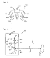
- FIG. 3 shows a schematic cross-sectional view of a laser scanner 200 as a further possible sensor type for the optoelectronic sensor 24a-b.
- a light emitter 202 emits short light pulses.
- the transmitted light beam is formed by a transmission optics 204 and passes through a splitter mirror 206 before it on a rotatable scanning mirror 208 falls.
- the scanning mirror 208 is embodied, for example, as a rotating mirror or as a polygon mirror wheel and, by virtue of its rotational movement in accordance with the arrow 210, ensures that the transmitted light beam periodically scans the spatial region 10.
- a plane is monitored with a scan mirror 18 which is movable only in one axis. With an additional movement mechanism for the scanning mirror 208, a three-dimensional space region can also be scanned.
- the transmitted light falls after passing through a front screen 212 on an object 214 and is there at least partially remitted to the laser scanner 200 or reflected.
- the received light beam is registered after beam shaping in a receiving optical system 216 in a light receiving element 218, for example a photodiode.
- a control unit 220 determines the duration of the light pulses from the time of transmission to the light emitter 202 to the detection in the light receiving element 218 and calculates the distance of the object 214 via the speed of light. With each periodic rotational movement of the scanning mirror 208, an image with a distance profile of Objects 214 in the space area 10. The image has a resolution in the angular direction, which depends on the pulse rate of the transmission pulse to the light emitter 202 and the rotational speed of the scanning mirror 208. In it, people can be identified by their profiles and their position and number can be determined.
- the output data of the laser scanner 220 is available at an output 222 for further processing.
- a phase-based laser scanner can also be used.
- multiple laser scanners 200 may be combined to monitor a worker island 20a-c.
- the above-mentioned properties and standards apply analogously.
- the individual sensors that is to say the access control device 18 and the monitoring sensors 22a-b, as well as the machines 16a-c are interconnected via a controller 28, as shown schematically in FIG FIG. 4 shown.
- the controller receives raw data or already processed positions, numbers or personal information.
- the Controller 28 outputs a shutdown signal via secure outputs 30 (OSSD, Output Signal Switching Device) to the machines 16a-c after appropriate allocation or releases them for an automated process step.
- secure outputs 30 (OSSD, Output Signal Switching Device)
- FIG. 5 illustrates the secure determination of the number of persons 14a-c in the space area 10.
- a first step S10 the initial number of persons 14a-c in the space area 10 is set manually. In doing so, the operator ensures that the room area 10 is free, or specifies the number of persons visually counted in the room area 10.
- the access 12 Upon receipt of the actual operation of the access control device 18 in a second step S11, the access 12 is monitored until a person 14c is detected there. For each person 14c optically detected by the sensor 18a, properties are stored, for example colors, sizes or contours. A second sensor 18b, for example an RFID reader 18b or a step mat, must also recognize the person 14c. If in an embodiment with RFID reader 18b objects in the access lock 12 are optically detected without a transponder being assigned, this leads to a stop or locking state of the system because the person 14c may not be authorized to enter the room area 10 , A person 14c without a transponder could then later not be recognized or tracked (tracked) within the spatial area 10 by the RFID readers 26a-b. Even if the recognized person 14c leaves the access lock 12 to the outside, the transponder must be recognized, because only so the number of people can be safely counted down.
- the detected person 14c leaves the access lock 12 either in a step S12 to the outside or in a step S13 in the direction of the space area 10. Accordingly, in steps S14 and S15, the number of people in the space area 10 is increased or decreased. In addition, when the person 14c enters the space area, personal information such as color, size, outline or tag ID is stored in a step S16.
- a step S20 two situations are summarized. Either the system is already in operation and performs an automatic process step, or it should be started to start an automatic process step.
- a step S21 it is then checked with the aid of the monitoring sensors 22a-b how many of the persons 14a-c are located on the worker islands 20a-c. If this number corresponds to the known total number of persons 14a-c in the space area 10 in a step S22, the operation of the installation is started or continued in a step S23, and the check is continued cyclically in step S21 to ensure that furthermore, all persons 14a-c are located on Worker Islands 20a-c.
- the personal information stored in the step S16 may be used to assist.
- the sensors 22a-b may constantly attempt to track the persons 14a-e even if they are not on the worker's islands 20a-c. This will sometimes not succeed if the persons 14a-e emerge from the detection area or are not detectable in blind parts of the system. Then the person tracking is continued as soon as an unassigned person can be recaptured. Confusion here is not relevant, since primarily the number of persons 14a-e on factory islands 20a-c over operation or stop or lock decides. Gaps in the doctrine of persons also do not affect the security since the intention of persons facilitates or makes plausible the registration on the worker islands 20a-c only.
Abstract
Description
Die Erfindung betrifft eine Sicherungsvorrichtung und ein Verfahren zur Absicherung eines nur über eine sichere Zugangsschleuse zugänglichen Raumbereichs nach dem Oberbegriff von Anspruch 1 beziehungsweise Anspruch 10.The invention relates to a security device and a method for securing a space region accessible only via a secure access lock according to the preamble of claim 1 or claim 10.
Im industriellen Umfeld gibt es häufig kooperative Arbeitsplätze, in denen Werker und Roboter oder andere Maschinen abwechselnd Prozess- oder Arbeitsschritte durchführen. Beispiele sind Einlegestationen, Werkerbühnen oder Drehtischanwendungen ohne trennende Schutzeinrichtung. Dabei müssen die Werker während der Arbeitsschritte der Maschine geschützt werden. Die Maschine darf deshalb nur anlaufen, wenn sich kein Werker in dem durch ihren automatischen Arbeitsschritt gefährdeten Bereich befindet.In the industrial environment, there are often cooperative workplaces in which workers and robots or other machines alternately carry out process or work steps. Examples are insertion stations, work platforms or turntable applications without guards. The workers must be protected during the working steps of the machine. Therefore, the machine may only be started if no worker is in the area which is at risk due to its automatic work step.
Es gibt verschiedene herkömmliche Wege, um dies sicherzustellen. Nach einer herkömmlichen Lösung wird der Werker durch eine mechanische oder auch berührungslose Zugangsabsicherung vor dem automatischen Prozessschritt geschützt. Dabei muss der Werker zyklisch durch eine Tür oder sonstige Absicherung aus dem Gefahrenbereich gehen und durch Betätigen einer Wiederanlaufsperre den automatischen Prozessschritt starten. Durch die erforderliche mechanische Absicherung wird die Flexibilität der Anlage erheblich beschränkt.There are several conventional ways to ensure this. After a conventional solution, the worker is protected by a mechanical or non-contact access protection before the automatic process step. The worker has to leave the danger zone cyclically through a door or other protection and start the automatic process step by pressing a restart interlock. The required mechanical protection considerably limits the flexibility of the system.
Nach eine anderen Lösung überwacht ein Sensor ein vordefiniertes Schutzfeld in dem Gefahrenbereich. Das kann ein Laserscanner mit einem horizontalen Schutzfeld, aber auch eine sichere Trittmatte in dem Gefahrenbereich sein. Solange sich in dem Schutzfeld oder auf der Trittmatte unzulässige Objekte befinden, wird ein Anlaufen der Maschine verhindert, indem über Sicherheitsschaltausgänge ein Stoppsignal ausgegeben beziehungsweise eine Freigabe verweigert wird. Nachteilig hieran ist, dass es in manchen Anwendungen nur sehr schwer oder unmöglich ist, Personen in dem gesamten Gefahrenbereich sicher zu erfassen. Ursachen sind Anlagenteile oder Material in dem Gefahrenbereich, die nicht oder nur schwer von Personen unterscheidbar sind. Auch können Werker den Gefahrenbereich hintertreten. Optische Sensoren sind außerdem in störanfälligen Umgebungen nur eingeschränkt verfügbar, etwa bei prozessbedingten Verunreinigungen durch Sägespäne oder Sägestaub in der Holzbearbeitung, bei Schweißfunken, oder bei Regen, Nebel oder Schnee in Außenanwendungen.According to another solution, a sensor monitors a predefined protective field in the danger zone. This can be a laser scanner with a horizontal protective field, but also a safe step mat in the danger zone. As long as there are illegal objects in the protective field or on the running mat, starting up of the machine is prevented by outputting a stop signal via safety switching outputs or a release is denied. The disadvantage of this is that in some applications it is very difficult or impossible to reliably detect persons in the entire danger area. Causes are system parts or material in the danger zone that are not or only with difficulty distinguishable from persons. Also, workers can enter the danger area. Optical sensors are also limited in troubled environments, such as process-related contamination by sawdust or saw dust in woodworking, welding sparks, or in rain, fog or snow in outdoor applications.
Bei allen herkömmlichen Lösungen wird die Gesamtprozesszyklusdauer stark durch die Zeit für die Quittierung oder das Anstarten vor jedem automatischen Prozessschritt durch den Werker bestimmt. Der Werker muss zunächst visuell sicherstellen, dass sich keine Personen innerhalb des Gefahrenbereichs aufhalten. Da es sich oft um sehr monotone Abläufe handelt, lässt die Sorgfalt und Konzentration bei dieser Prüfung mit der Zeit nach. Gerade in unübersichtlichen Anlagen können dann Personen übersehen werden, die sich innerhalb der Anlage befinden. Das führt im besten Fall zu einer Verzögerung, wenn Sensoren die Person erkennen und eine Notabschaltung auslösen, im schlimmsten Fall sogar zu einer Verletzung der Person, wenn die Anlage erneut startet.In all conventional solutions, the overall process cycle time is largely determined by the time for acknowledgment or startup prior to each automated process step by the worker. The worker must first visually ensure that no persons are within the danger zone. Since these are often very monotonous processes, the care and concentration in this test diminishes over time. Especially in confusing systems then people can be overlooked, which are located within the system. At best, this will delay if sensors detect the person and cause an emergency shutdown, in the worst case even a personal injury when the system restarts.
Aus der
Es ist daher Aufgabe der Erfindung, einen automatisierten und zuverlässigen Schutz an kooperativen Arbeitsplätzen zu erreichen.It is therefore an object of the invention to achieve an automated and reliable protection of cooperative workstations.
Diese Aufgabe wird durch eine Sicherungsvorrichtung nach Anspruch 1 und ein Verfahren zur Absicherung eines nur über eine sichere Zugangsschleuse zugänglichen Raumbereichs nach Anspruch 10 gelöst. Dabei geht die Erfindung von dem Grundgedanken aus, das übliche Sicherheitskonzept umzukehren: Statt den eigentlichen Gefahrenbereich, also die Umgebung der Gefahrenquelle daraufhin zu prüfen, ob sich dort Personen oder unzulässige Objekte befinden, wird die Anzahl und Position der Personen an dem kooperativen Arbeitsplatz kontrolliert. Dazu wird die Anlage in einem Raumbereich untergebracht, der nur durch eine Zugangsschleuse zugänglich ist, an welcher der Ein- und Austritt von Personen überwacht wird. Sind beim Anfahren oder während des Betriebs der Anlage alle an der Zugangsschleuse gezählten Personen an einem sicheren Ort erkannt, nämlich der Werkerinsel, so ist ausgeschlossen, dass eine Person gefährdet wird.This object is achieved by a security device according to claim 1 and a method for securing a accessible only via a secure access lock space area according to
Der Begriff "Abschaltsignal" schließt neben einer Abschaltung auch die Verweigerung einer Einschaltung ein. Der Begriff "sicher" ist jeweils im Sinne einschlägiger Sicherheitsnormen zu verstehen. Zur Vereinfachung wird in den Ansprüchen nur jeweils von einem Zugang, einer Werkerinsel und einer Gefahrenquelle gesprochen. Selbstverständlich können ebenso auch mehrere Zugänge, Werkerinseln oder Gefahrenquellen vorhanden sein.The term "shutdown signal" includes in addition to a shutdown and the refusal of an intervention. The term "safe" should be understood in accordance with relevant safety standards. For simplicity, only one access, one worker island and one source of danger are spoken in the claims. Of course, as well as several access points, workers islands or sources of danger may be present.
Die Zugangskontrolleinrichtung gewinnt ihre Informationen über die Anzahl der in dem Raumbereich vorhandenen Personen üblicherweise nur differentiell, weiß also nur, um wie viel sich die Anzahl ändert. Die Absolutzahlen werden daraus mit einem Anfangswert gewonnnen, beispielsweise indem bei erster Inbetriebnahme der Sicherungsvorrichtung unabhängig sichergestellt wird, dass der Raumbereich leer ist.The access control device usually wins its information about the number of persons present in the area only differentially, so only knows how much the number changes. The absolute numbers are obtained therefrom with an initial value, for example, by independently ensuring at first startup of the security device that the space area is empty.
Die Erfindung hat den Vorteil, dass eine übersichtliche Werkerinsel statt der oft schwer einsehbaren, hintertretbaren oder durch Maschinenteile und den automatisierten Prozessschritt unübersichtlichen Umgebung der Gefahrenquelle überwacht wird. Damit wird ein zuverlässiges automatisiertes Anfahren der Anlage auch in stark gestörten Umgebungen ermöglicht. Es gibt keinen Werker, der dafür verantwortlich ist festzustellen, ob sich beim Maschinenstart Personen in der Nähe der Gefahrenquelle aufhalten, und damit keine Konzentrationsfehler oder dergleichen. Da somit die Überprüfung des Raumbereichs durch den Werker entfällt, wird die Zykluszeit des gesamten kooperativen Prozesses optimiert. Der Aufenthalt von unbefugten Personen im Raumbereich wird durch die Zugangsschleuse verhindert.The invention has the advantage that a clearer operator island is monitored instead of the often difficult to see, behind-the-scene or by machine parts and the automated process step confusing environment of the source of danger. This enables reliable automated start-up of the system even in severely disturbed environments. There is no worker who is responsible for determining if people are near the source of danger at engine startup, and thus no concentration errors or the like. Since the worker does not have to check the room area, the cycle time of the entire cooperative process is optimized. The access of unauthorized persons in the area is prevented by the access lock.
Die Werkerinsel-Überwachungseinrichtung weist bevorzugt eine erste optoelektronische Sensoreinheit auf. Optoelektronische Sensoren sind in großer Vielfalt bekannt und in der Lage, berührungslos, rasch und zuverlässig die Personen auf der Werkerinsel zu detektieren.The worker island monitoring device preferably has a first optoelectronic sensor unit. Photoelectric sensors are widely known and capable of detecting contactless, fast and reliable people on the workman island.
Die erste Sensoreinheit weist vorteilhafterweise eine Kamera, insbesondere eine Stereoskopiekamera oder eine Lichtlaufzeitkamera, oder mindestens einen Laserscanner, insbesondere einen 3D-Laserscanner oder eine Anordnung mehrerer entfernungsmessender zweidimensionaler Laserscanner auf. Diese Sensortypen sind für die Aufgabe, Personen auf der Werkerinsel zu detektieren und zu zählen, besonders geeignet.The first sensor unit advantageously has a camera, in particular a stereoscopic camera or a light runtime camera, or at least one laser scanner, in particular a 3D laser scanner or an arrangement of several distance-measuring two-dimensional laser scanner. These sensor types are particularly suitable for the task of detecting and counting people on the worker's island.
Die Werkerinsel-Überwachungseinrichtung weist vorteilhafterweise eine zweite Sensoreinheit auf, um so die Anwesenheit und Anzahl von Personen auf der Werkerinsel mit der ersten Sensoreinheit und der zweiten Sensoreinheit diversitär-redundant zu bestimmen. Diversitär-redundant bedeutet über die doppelte, also redundante Auslegung hinaus, dass die zweite Sensoreinheit sich technisch von der ersten Sensoreinheit unterscheidet. Damit ist die Sicherheit gegenüber möglichen Fehlern erhöht, denn die Wahrscheinlichkeit ist erheblich reduziert, dass ein und derselbe Fehler beide Sensoreinheiten betrifft. Diversitär wäre schon der Einsatz zweier optoelektronischer Sensoren desselben Typs, aber unterschiedlicher Bauart, also beispielsweise zwei nicht baugleiche Laserscanner. Noch stärker diversitär ist die Mischung unterschiedlicher Typen, beispielsweise eine Kamera mit einem Laserscanner. Am robustesten ist die Nutzung gänzlich unterschiedlicher Technologien, beispielsweise ein optoelektronisches und ein mechanisches System.The worker island monitoring device advantageously has a second sensor unit so as to determine the presence and number of persons on the worker island with the first sensor unit and the second sensor unit diversified-redundant. Diversitively redundant means beyond the double, ie redundant design, that the second sensor unit differs technically from the first sensor unit. This increases the security against possible errors, since the probability is significantly reduced that the same error affects both sensor units. Diverse would be the use of two optoelectronic sensors of the same type, but of different types, so for example two not identical laser scanner. Even more diversified is the mixture of different types, for example a camera with a laser scanner. The most robust is the use of completely different technologies, such as an optoelectronic and a mechanical system.
Die zweite Sensoreinheit weist bevorzugt einen RFID-Leser, eine Trittmatte, eine Zweihandschaltung oder einen Gewichtssensor auf. Im Falle von RFID tragen Personen, die den Raumbereich betreten, ein entsprechendes RFID-Tag. Die zweite Sensoreinheit arbeitet ganz anders als ein optoelektronischer Sensor. Selbst wenn also der Raumbereich stark optisch gestört wird, etwa durch Staub oder sehr helle Lichtquellen, so bleibt die Funktion der zweiten Sensoreinheit erhalten. Es sind kaum realistische Situationen vorstellbar, in denen sowohl ein optoelektronischer als auch ein auf RFID oder mechanischen Einflüssen wie Druck basierender Sensor gleichzeitig versagen.The second sensor unit preferably has an RFID reader, a step mat, a two-hand circuit or a weight sensor. In the case of RFID, people entering the room area carry a corresponding RFID tag. The second sensor unit works quite differently than an optoelectronic sensor. Even if, therefore, the room area is strongly disturbed optically, for example by dust or very bright light sources, the function of the second sensor unit is maintained. Hardly realistic situations are conceivable in which both an optoelectronic sensor and a sensor based on RFID or mechanical influences such as pressure fail at the same time.
Die erste Sensoreinheit und/oder die zweite Sensoreinheit ist bevorzugt zugleich als Zugangskontrolleinrichtung ausgebildet. Damit ist kein anderes System für die Überwachung des Zugangs erforderlich. Als Zugangsschleuse ist aber auch alternativ eine Tür, eine Drehtür oder ein Drehgitter denkbar, wobei zusätzlich eine Authentifizierung erfolgen kann, etwa durch Sicherheitsschloss mit Magnetkarte, PIN-Code oder dergleichen. Unbefugte Personen werden damit von vorneherein aus dem Raumbereich ausgeschlossen.The first sensor unit and / or the second sensor unit is preferably also designed as an access control device. No other system is required to monitor access. As an access lock but also a door, a revolving door or a rotating screen is alternatively conceivable, in addition, an authentication can be done, such as security lock with magnetic card, PIN code or the like. Unauthorized persons are thus excluded from the outset from the room area.
In einer bevorzugten Weiterbildung ist die Werkerinsel-Überwachungseinrichtung dafür ausgebildet, Personen auch außerhalb der Werkerinsel zu erkennen und ihre Bewegung zu verfolgen. Durch eine Personenverfolgung beziehungsweise ein Objekttracking, welches schon mit Durchtritt der Zugangsschleuse einsetzen kann, wird zusätzliche Sicherheit gewonnen, ob sich alle Personen auf der Werkerinsel befinden. Eine lückenlose Personenverfolgung beziehungsweise ein Objekttracking wird wegen anderer, ungefährlicher Objekte im Gefahrenbereich, Bewegungen der Gefahrenquelle oder der Anlage, einem nur begrenztem Überwachungsbereich sowie Störungen häufig nicht möglich sein. Die Personenverfolgung setzt deshalb bevorzugt immer wieder neu an, sobald irgendwo im Raumbereich eine Person erkannt ist. Damit werden für die Funktion der Werkerinsel-Überwachungseinrichtung günstige Anfangsbedingungen geschaffen, und deren Erkennung kann stets plausibilisiert werden.In a preferred embodiment, the worker island monitoring device is designed to detect persons outside the worker's island and to track their movement. Through a person tracking or an object tracking, which can already use with passage of the access lock, additional security is gained, whether all persons are on the worker's island. Seamless tracking or object tracking will often not be possible due to other, non-hazardous objects in the danger area, movements of the source of danger or the facility, a limited surveillance area and disturbances. The pursuit of persons therefore prefers to re-start whenever a person is recognized somewhere in the area. In order for the function of the worker island monitoring device favorable initial conditions are created, and their detection can always be made plausible.
Die Zugangskontrolleinrichtung ist bevorzugt dafür ausgebildet, Personeninformationen über Eigenschaften der in den Gefahrenbereich eintretenden Personen zu gewinnen, insbesondere über Gewicht, Farbe, Kontur oder Größe der Person, wobei der Werkerinsel-Überwachungseinrichtung die Personeninformation für die Erkennung der Anwesenheit und Anzahl von Personen auf der Werkerinsel zur Verfügung steht. Das erleichtert die Erkennung von Personen und erhöht deren Sicherheit. Hat beispielsweise ausschließlich eine dunkel gekleidete, große und schwere Person den Raumbereich betreten, und wird später zum Maschinenstart eine hell gekleidete, kleine und leichte Person auf der Werkerinsel erkannt, so liegt vermutlich ein Erkennungsfehler vor.The access control device is preferably designed to obtain personal information about the characteristics of persons entering the danger zone, in particular about the weight, color, contour or size of the person, whereby the worker island monitoring device displays the personal information for the detection of the presence and number of persons on the worker island is available. This facilitates the detection of persons and increases their safety. For example, if only a dark-clad, tall and heavy person has entered the room area, and if a brightly-dressed, small and light person is recognized later on the worker's island, then there is probably a recognition error.
In bevorzugter Weiterbildung unterstützt die Werkerinsel die optoelektronische Erkennung von Personen und weist insbesondere einen hellen, dunklen oder gelben Hintergrund oder ein Kontrastmuster auf oder ist frei von Gegenständen, Metall und/oder spiegelnden Flächen. Damit kann die Erkennungssicherheit der Sensoren ganz erheblich gesteigert werden, und die Verfügbarkeit der Anlage steigt. Dies ist ein großer Vorteil der Erfindung, denn die herkömmlich überwachte Umgebung der Gefahrenquelle lässt sich kaum beeinflussen und bietet oft nur schwierige Verhältnisse für eine automatisierte Überwachung an, da sie durch die Anlage bestimmt wird. Die Werkerinsel dagegen lässt sich unabhängig von der Anlage optimal für den Sensor präparieren und bietet dann einen vorhersehbaren und einfachen Hintergrund für die Detektion von Personen.In a preferred embodiment, the worker's island supports the opto-electronic detection of persons and in particular has a light, dark or yellow background or a contrast pattern or is free of objects, metal and / or reflective surfaces. This significantly increases the detection reliability of the sensors and increases the availability of the system. This is a great advantage of the invention, since the conventionally monitored environment of the source of danger is difficult to influence and often provides only difficult conditions for automated monitoring since it is determined by the plant. By contrast, the worker island can be optimally prepared for the sensor independently of the system and then provides a predictable and simple background for the detection of persons.
Das erfindungsgemäße Verfahren kann auf ähnliche Weise weitergebildet werden und zeigt dabei ähnliche Vorteile. Derartige vorteilhafte Merkmale sind beispielhaft, aber nicht abschließend in den sich an die unabhängigen Ansprüche anschließenden Unteransprüchen beschrieben.The method according to the invention can be developed in a similar manner and shows similar advantages. Such advantageous features are described by way of example but not exhaustively in the subclaims following the independent claims.
Die Erfindung wird nachstehend auch hinsichtlich weiterer Merkmale und Vorteile beispielhaft anhand von Ausführungsformen und unter Bezug auf die beigefügte Zeichnung näher erläutert. Die Abbildungen der Zeichnung zeigen in:
- Fig. 1
- eine schematische Draufsicht auf einen nur kontrolliert zugänglichen Raumbereich, der durch eine Ausführungsform der erfindungsgemäßen Si- cherungsvorrichtung abgesichert wird;
- Fig. 2
- eine schematische Darstellung einer Stereokamera als Beispiel eines op- toelektronischen Sensors, der in einer erfindungsgemäßen Sicherungsvor- richtung einsetzbar ist;
- Fig. 3
- eine schematische Darstellung eines Laserscanners als weiteres Beispiel eines optoelektronischen Sensors, der in einer erfindungsgemäßen Siche- rungsvorrichtung einsetzbar ist;
- Fig. 4
- eine schematische Blockdarstellung der Steuerung einer erfindungsgemä- ßen Sicherungsvorrichtung;
- Fig. 5
- ein Ablaufdiagramm der Zugangskontrolle an der Zugangsschleuse einer erfindungsgemäßen Sicherungsvorrichtung; und
- Fig. 6
- ein Ablaufdiagramm beim Maschinenstart in einer Anlage, die durch eine erfindungsgemäße Sicherungsvorrichtung abgesichert ist.
- Fig. 1
- a schematic plan view of a controlled only accessible space area, which is secured by an embodiment of the safety device according to the invention;
- Fig. 2
- a schematic representation of a stereo camera as an example of an optoelectronic sensor, which can be used in a securing device according to the invention;
- Fig. 3
- a schematic representation of a laser scanner as another example of an optoelectronic sensor, which is used in a fuse according to the invention insurance device;
- Fig. 4
- a schematic block diagram of the control of a security device according to the invention;
- Fig. 5
- a flow chart of access control at the access lock of a security device according to the invention; and
- Fig. 6
- a flowchart when starting the machine in a system that is protected by a security device according to the invention.
In dem Raumbereich 10 befindet sich ein kooperativer Arbeitsplatz mit einer Anlage, an dem Personen 14a-e und Maschinen 16a-c abwechselnd Prozessschritte ausführen. Die Anlage selbst sowie deren Verarbeitungsprodukte sind zur Vereinfachung nicht dargestellt. Arbeitsbewegungen der Maschinen 16a-c, etwa von Roboterarmen, bilden potentiell eine Gefahr für die Personen 14a-e, so dass während der Aktivität der Maschinen 16a-c die Personen 14a-e sich nicht in deren Arbeitsradius aufhalten dürfen. An dem Zugang 12 befindet sich eine Zugangskontrolleinrichtung 18, welche den Zugang 12 zu einer sicheren Zugangsschleuse macht. Der Raumbereich 10 ist so gestaltet, dass Personen 14a-e nur durch diese sichere Zugangsschleuse ein- oder austreten können. Die Zugangskontrolleinrichtung 18 erkennt und zählt Personen 14a-e, welche den Raumbereich 10 betreten oder verlassen. Somit ist die Anzahl in dem Raumbereich 10 befindlicher Personen 14a-c stets bekannt, sofern bei Aktivierung der Zugangskontrolleinrichtung 18 ein korrekter Anfangswert vorgegeben wurde.In the
In
Innerhalb des Raumbereichs 10 sind Werkerinseln 20a-c eingerichtet, auf denen während der Bewegungen der Maschinen 16a-c keine Gefährdung für die Personen 14a-e besteht. Überwachungssensoren 22a-b erfassen und zählen Personen 14a-e auf den Werkerinseln 20a-c. Es ist abweichend von der Darstellung auch denkbar, dass ein Überwachungssensor 22a-b mehrere Werkerinseln 20a-c überwacht oder umgekehrt mehrere Überwachungssensoren 22a-b an einer Werkerinsel 20a-c montiert sind. Die Maschinen 16a-c können nur in Betrieb gehen, wenn alle in dem Raumbereich 10 befindlichen Personen 14a-c auf Werkerinseln 20a-c erfasst sind, und sie werden sofort durch ein sicheres Abschaltsignal angehalten, wenn eine Person 14b eine Werkerinsel 20 verlässt.Within the
In dem Beispiel der
Die Überwachungssensoren 22a-b bestehen jeweils aus zwei Sensoreinheiten, nämlich einem optoelektronischen Sensor 24a-b und einem RFID-Leser 26a-b. Beispiele für die Ausführung der optoelektronischen Sensoren 24a-b werden weiter unten im Zusammenhang mit den
Die RFID-Leser 26a-b erkennen RFID-Tags, mit denen die Personen 14a-e ausgerüstet sind, etwa in ihrer Arbeitskleidung oder im Schuhabsatz integriert. Durch entsprechende Anordnungen und Abschirmungen ist sichergestellt, dass die RFID-Leser 26a-b nur RFID-Tags der ihnen zugeordneten Werkerinseln 20a-c lesen. Alternativ können die RFID-Leser 26a-b die gelesenen RFID-Tags auch lokalisieren. Anstelle von RFID-Lesern 26a-b sind auch Trittmatten, Zweihandschaltungen, Gewichtssensoren und anderes einsetzbar. Die Sicherheit wird erhöht, wenn die hier verwendete Technologie möglichst unterschiedlich zu optoelektronischer Detektion ist.The
Obwohl die Zugangskontrolleinrichtung 18 prinzipiell beliebig ausgeführt sein kann, etwa als mechanische Drehtür, ist vorteilhaft, wenn sie ebenfalls einen optoelektronischen Sensor 18a und einen RFID-Leser 18b aufweist. Dann muss keine zusätzliche Technologie integriert werden, und bereits an der Zugangsschleuse 12 können gleichartige Daten erhoben werden wie später an den Werkerinseln 20a-c, womit dort die Detektion vereinfacht oder gegengeprüft wird. Idealerweise ist sogar insgesamt nur ein Sensor vorhanden, welcher die Funktionalität der Zugangskontrolleinrichtung 18 und der Überwachungssensoren 20a-b zugleich wahrnimmt.Although the
Als optoelektronischer Sensor 24a-b sind eine Reihe von Sensortypen geeignet.
In der Mitte zwischen den beiden Bildsensoren 104a-b ist eine Beleuchtungseinheit 108 dargestellt, wobei diese räumliche Anordnung nur als Beispiel zu verstehen ist und die Beleuchtungseinheit ebenso asymmetrisch oder sogar außerhalb der 3D-Kamera 108 angeordnet sein kann. Die Beleuchtungseinheit 108 erzeugt auf der überwachten Werkerinsel 20a-c ein strukturiertes Beleuchtungsmuster, das mit dem Hintergrund der Werkerinsel 20a-c einen hohen Kontrast bildet.In the middle between the two
Mit den beiden Bildsensoren 104a-b und der Beleuchtungseinheit 108 ist eine Steuerung 110 verbunden, welche Bilddaten der Bildsensoren 104a-b empfängt. Aus diesen aus leicht unterschiedlichen Perspektiven gewonnenen Bilddaten berechnet die Steuerung 110 mit Hilfe einer stereoskopischen Disparitätsschätzung dreidimensionale Bilddaten. Das Beleuchtungsmuster sorgt dabei für einen guten Kontrast und, besonders wenn es selbstunähnlich ist, eine eindeutig zuordenbare Struktur jedes Bildelements. In den dreidimensionalen Bilddaten werden Personen 14a-e erkannt und können so in Position und Anzahl bestimmt werden. Diese Daten sind an einem Anschluss 112 abrufbar.Connected to the two
Um für sicherheitstechnische Anwendungen geeignet zu sein, ist die 3D-Kamera 100 fehlersicher ausgelegt. Dies bedeutet unter anderem, dass sich die 3D-Kamera 100 selber, auch in Zyklen unterhalb der geforderten Ansprechzeit, testen kann, insbesondere auch Defekte der Beleuchtungseinheit 108 erkennt und somit sicherstellt, dass das Beleuchtungsmuster in einer erwarteten Mindestintensität verfügbar ist, und dass der Anschluss 112 sicher, beispielsweise zweikanalig ausgelegt ist. Ebenso ist auch die Steuerung 110 selbstsicher, wertet also zweikanalig aus oder verwendet Algorithmen, die sich selbst prüfen können. Derartige Vorschriften sind für allgemeine berührungslos wirkende Schutzeinrichtungen in der EN 61496-1 bzw. der IEC 61496 sowie in der DIN EN ISO 13849 und EN 61508 normiert. Eine entsprechende Norm für Sicherheitskameras befindet sich in der Vorbereitung.To be suitable for safety applications, the
Anstelle einer stereoskopischen 3D-Kamera 100 ist auch der Einsatz einer zweidimensionalen Kamera mit entsprechender Bildverarbeitung oder einer Lichtlaufzeitkamera denkbar. Lichtlaufzeitkameras werten Laufzeiten ihres Sendelichts in jedem Pixel ihres matrixförmigen Bildsensors aus, beispielsweise mittels Photonmischdetektion, und erzeugen ebenfalls dreidimensionale Bilder.Instead of a
Das Sendelicht fällt nach Durchtritt durch eine Frontscheibe 212 auf ein Objekt 214 und wird dort zumindest teilweise zu dem Laserscanner 200 remittiert oder reflektiert. Nach zweifacher Umlenkung an dem Scanspiegel 208 und dem Teilerspiegel 206 wird das Empfangslichtbündel nach Strahlformung in einer Empfangsoptik 216 in einem Lichtempfangselement 218 registriert, beispielsweise einer Photodiode.The transmitted light falls after passing through a
Eine Steuereinheit 220 ermittelt die Laufzeit der Lichtpulse vom Zeitpunkt der Aussendung an dem Lichtsender 202 bis zur Detektion in dem Lichtempfangselement 218 und errechnet daraus über die Lichtgeschwindigkeit die Entfernung des Objekts 214. Mit jeder periodischen Drehbewegung des Scanspiegels 208 entsteht so ein Bild mit einem Entfernungsprofil der Objekte 214 in dem Raumbereich 10. Das Bild hat in Winkelrichtung eine Auflösung, die von der Pulsfrequenz des Sendepulses an dem Lichtsender 202 und der Drehgeschwindigkeit des Scanspiegels 208 abhängt. Darin können Personen anhand ihrer Profile erkannt und ihre Position und Anzahl bestimmt werden. Die Ausgangdaten des Laserscanners 220 stehen an einem Ausgang 222 für die weitere Verarbeitung zur Verfügung.A
Anstelle des beschriebenen pulsbasierten Laserscanners 200 ist auch ein phasenbasierter Laserscanner einsetzbar. Auch können mehrere Laserscanner 200 kombiniert werden, um eine Werkerinsel 20a-c zu überwachen. Hinsichtlich der Sicherheit des Laserscanners gelten die oben genannten Eigenschaften und Normen analog.Instead of the pulse-based
Die einzelnen Sensoren, also die Zugangskontrolleinrichtung 18 und die Überwachungssensoren 22a-b, sowie die Maschinen 16a-c sind über eine Steuerung 28 miteinander verschaltet, wie schematisch in
Abschließend wird der Ablauf der Absicherung anhand der
Mit Aufnahme des eigentlichen Betriebs der Zugangskontrolleinrichtung 18 in einem zweiten Schritt S11 wird der Zugang 12 so lange überwacht, bis dort eine Person 14c erfasst ist. Zu jeder von dem Sensor 18a optisch erfassten Person 14c werden Eigenschaften gespeichert, beispielsweise Farben, Größen oder Konturen. Ein zweiter Sensor 18b, beispielsweise ein RFID-Leser 18b oder eine Trittmatte, muss die Person 14c ebenfalls erkennen. Werden bei einer Ausführungsform mit RFID-Leser 18b Objekte in der Zugangsschleuse 12 optisch erfasst, ohne dass ein Transponder zugeordnet werden kann, so führt dies zu einem Stop oder Verriegelungszustand der Anlage, weil die Person 14c möglicherweise nicht befugt ist, den Raumbereich 10 zu betreten. Eine Person 14c ohne Transponder könnte dann auch später innerhalb des Raumbereichs 10 von den RFID-Lesern 26a-b nicht erkannt oder verfolgt (getrackt) werden. Auch wenn die erkannte Person 14c die Zugangsschleuse 12 nach außen verlässt, muss der Transponder erkannt werden, weil nur so die Personenanzahl sicher herabgezählt werden darf.Upon receipt of the actual operation of the
Die erfasste Person 14c verlässt die Zugangsschleuse 12 entweder in einem Schritt S12 nach außen oder in einem Schritt S13 in Richtung des Raumbereichs 10. Entsprechend wird in Schritten S14 beziehungsweise S15 die Personenzahl in dem Raumbereich 10 herab- oder heraufgesetzt. Wenn die Person 14c den Raumbereich betritt, werden außerdem in einem Schritt S16 Personeninformationen gespeichert, also beispielsweise Farbe, Größe, Kontur oder Tag-ID.The detected
Mit dem Ablauf gemäß
In einem Schritt S20 sind zwei Situationen zusammengefasst. Entweder ist die Anlage bereits im Betrieb und führt einen automatischen Prozessschritt aus, oder sie soll gestartet werden, um einen automatischen Prozessschritt zu beginnen. In einem Schritt S21 wird dann mit Hilfe der Überwachungssensoren 22a-b geprüft, wie viele der Personen 14a-c sich auf Werkerinseln 20a-c befinden. Entspricht diese Anzahl in einem Schritt S22 der bekannten Gesamtzahl von Personen 14a-c in dem Raumbereich 10, so wird der Betrieb der Anlage in einem Schritt S23 aufgenommen oder fortgesetzt, und die Überprüfung wird zyklisch bei Schritt S21 fortgesetzt, um zu gewährleisten, dass sich weiterhin alle Personen 14a-c auf Werkerinseln 20a-c befinden. Sobald und solange also alle im Raumbereich 10 erfassten Personen 14a-c in den Werkerinseln 20a-c erkannt sind, kann der gefährliche Prozess ohne auslösendes Startsignal eines Werkers gestartet und anschließend sicher fortgesetzt werden. Dann haben alle Personen 14a-e eine ungefährliche Position eingenommen. Sobald dagegen die Gesamtzahl der Personen 14a-e auf Werkerinseln 20a-c nicht der Gesamtzahl der Personen 14a-c in dem Raumbereich 10 entspricht, wird in einem Schritt S24 ein Alarm oder ein Nothalt ausgelöst oder die Inbetriebnahme verweigert.In a step S20, two situations are summarized. Either the system is already in operation and performs an automatic process step, or it should be started to start an automatic process step. In a step S21, it is then checked with the aid of the
Bei der Erfassung und Zählung der Personen 14a-e auf Werkerinseln 20a-c in dem Schritt S21 können zur Unterstützung die Personeninformationen verwendet werden, die in Schritt S16 gespeichert wurden. Außerdem können die Sensoren 22a-b ständig versuchen, die Personen 14a-e zu verfolgen, auch wenn sie sich nicht auf Werkerinseln 20a-c befinden. Das wird manchmal nicht gelingen, wenn die Personen 14a-e aus dem Erfassungsbereich treten oder in unübersichtlichen Anlagenteilen nicht erfassbar sind. Dann wird die Personenverfolgung fortgesetzt, sobald eine nicht zugeordnete Person wieder erfasst werden kann. Verwechslungen hierbei sind nicht relevant, da in erster Linie die Anzahl der Personen 14a-e auf Werkerinseln 20a-c über Betrieb oder Stopp beziehungsweise Verriegelung entscheidet. Auch Lücken in der Personenverfolgung beeinträchtigen die Sicherheit nicht, da die Personenverfolgung nur die Erfassung auf den Werkerinseln 20a-c erleichtert oder plausibilisiert.Upon detection and enumeration of the
- S10: Setze Anzahl Personen im Raum auf definierten Anfangswert [z.B. 0].S10: Set number of persons in the room to defined initial value [e.g. 0].
- S11: Warte, bis Person in Schleuse erkannt wird.S11: Wait until person is detected in lock.
- S12: Person verlässt Schleuse nach außen.S12: Person leaves the lock to the outside.
- S13: Person verlässt Schleuse nach innen.S13: Person leaves lock inside.
- S14: Setze Anzahl Personen herab.S14: Lower the number of people.
- S15: Setze Anzahl Personen herauf.S15: Set up the number of persons.
- S16: Speichere Personeninformationen.S16: Store personal information.
- S20: Anlage ist in Betrieb oder soll in Betrieb genommen werden.S20: System is in operation or should be put into operation.
- S21: Bestimme Anzahl Personen auf Werkerinseln.S21: Determine number of people on Workers' Islands.
- S22: Entspricht Gesamtzahl Personen auf Werkerinselnder Gesamtzahl Personen im Raum?S22: Does the total number of persons on works islands correspond to the total number of persons in the room?
- S23: Betrieb aufnehmen bzw. fortsetzen.S23: Start or continue operation.
- S24: Alarm / Nothalt /Verweigerte Inbetriebnahme.S24: Alarm / Emergency Stop / Denied Commissioning.
Claims (15)
- A securing apparatus for securing a spatial zone (10) having a danger source (16a-c) and accessible only via a secure access lock (12), wherein the securing apparatus has an access monitoring device (18) of the access lock (12) by which information on the number of persons (14a-e) located in the spatial zone (10) can be acquired,
characterised in that
a worker island (20a-c) is provided in the spatial zone (10), in which worker island the danger source (16a-c) does not endanger persons (14a-e); and in that the securing apparatus has a worker island monitoring device (22a-b) which is designed to determine the presence and number of persons (14a-e) on the worker island (20a-c) and also has a secure deactivation output (30) via which a deactivation signal can be output to the danger source (16a-c) if not all persons (14a-e) located in the spatial zone (10) are recognised on a worker island (20a-c). - A securing apparatus in accordance with claim 1,
wherein the worker island monitoring device (22a-b) has a first optoelectronic sensor unit (24a-b). - A securing apparatus in accordance with claim 2,
wherein the first sensor unit (24a-b) has a camera, in particular a stereoscopic camera (100) or a time-of-flight camera, or at least one laser scanner (200), in particular a 3D laser scanner or an arrangement of a plurality of distance measuring two-dimensional laser scaners. - A securing apparatus in accordance with claim 2 or claim 3,
wherein the worker island monitoring device (22a-b) has a second sensor unit (26a-b) in order thus to determine the presence and number of persons (14a-e) on the worker island (20a-c) using the first sensor unit (24a-b) and the second sensor element (25a-b) in a dissimilar redundant manner. - A securing apparatus in accordance with claim 4,
wherein the second sensor unit (26a-b) has an RFID reader, a pressure mat, a dual belt switch or a weight sensor. - A securing apparatus in accordance with any one of the claims 2 to 5,
wherein the first sensor unit (24a-b) and/or the second sensor unit (26a-b) is/are simultaneously designed as an access monitoring device (18a-b). - A securing apparatus in accordance with any one of the preceding claims,
wherein the worker island monitoring device (22a-b) is deigned also to recognise persons (14a-e) outside the worker island (20a-c) and to track their movement. - A securing apparatus in accordance with any one of the preceding claims,
wherein the access monitoring device (18) is designed to acquire personal information on properties of the persons (14a-e) entering the spatial zone (10), in particular on weight, colour, contour or size of the person (14a-e); and wherein the personal information for the recognition of the presence and number of persons (14a-e) on the worker island (20a-c) is provided to the worker island monitoring device (22a-b). - A securing apparatus in accordance with any one of the preceding claims,
wherein the worker island (20a-c) supports the optoelectronic recognition of persons (14a-e) and in particular has a bright, dark or yellow background or a contrast pattern or is free of objects, metal and/or reflective surfaces. - A method of securing a spatial zone (10) having a danger source (16a-c) and accessible only via a secure access lock (12), wherein persons entering the spatial zone (10) and leaving the spatial zone (10) are reliably registered in the access lock (12) and the number of persons (14a-e) located in the spatial zone (10) is reliably determined,
characterised in that
the presence and number of persons (14a-e) in a worker island (20a-e) inside the spatial zone (10) is determined, in which worker island the danger source (16a-c) cannot endanger persons (14a-e); and in that the danger source (16a-c) is secured by outputting a secure deactivation signal or the putting into operation of the danger source (16a-c) is prevented if not all persons (14a-e) located in the spatial zone (10) are recognised on a worker island (20a-c). - A method in accordance with claim 10,
wherein the presence and number of persons (14a-e) on the worker island (20a-c) is determined using a first optoelectronic sensor unit (24a-b). - A method in accordance with claim 11,
wherein the presence and number of persons (14a-e) on the worker island (20a-c) is monitored using the first optoelectronic sensor unit (24a-b) and a second sensor unit (26a-b) in a dissimilar redundant manner. - A method in accordance with claim 11 or claim 12,
wherein the access lock (12) is also monitored by the first sensor unit (24a-b) and/ (or the second sensor unit (26a-b) to register the persons (14a-e) entering the spatial zone (10) or leaving the spatial zone (10). - A method in accordance with any one of the claims 10 to 13, wherein personal information on properties of the persons (14a-e) located in the spatial zone (10) are acquired in the access lock (18), in particular on weight, colour, contour or size of the person (14a-e); and wherein the personal information is available for the recognition of the presence and number of persons (14a-e) on the worker island (20a-c).
- A method in accordance with any one of the claims 10 to 14, wherein the worker island (20a-c) is equipped for a better optoelectronic recognition of persons (14a-e), in particular by a bright, dark or yellow background or a contrast pattern or in that the worker island (20a-c) is kept free of objects, metal and/or reflective surfaces.
Applications Claiming Priority (1)
| Application Number | Priority Date | Filing Date | Title |
|---|---|---|---|
| DE102009036641A DE102009036641A1 (en) | 2009-08-07 | 2009-08-07 | Securing a space accessible only via a secure access lock |
Publications (2)
| Publication Number | Publication Date |
|---|---|
| EP2282106A1 EP2282106A1 (en) | 2011-02-09 |
| EP2282106B1 true EP2282106B1 (en) | 2011-09-07 |
Family
ID=43062603
Family Applications (1)
| Application Number | Title | Priority Date | Filing Date |
|---|---|---|---|
| EP10168655A Not-in-force EP2282106B1 (en) | 2009-08-07 | 2010-07-07 | Securing an area which can only be accessed through one secure access sluice |
Country Status (3)
| Country | Link |
|---|---|
| EP (1) | EP2282106B1 (en) |
| AT (1) | ATE523728T1 (en) |
| DE (1) | DE102009036641A1 (en) |
Cited By (1)
| Publication number | Priority date | Publication date | Assignee | Title |
|---|---|---|---|---|
| EP3910231A1 (en) * | 2020-05-11 | 2021-11-17 | Sick Ag | Safety system |
Families Citing this family (9)
| Publication number | Priority date | Publication date | Assignee | Title |
|---|---|---|---|---|
| DE102012102236A1 (en) * | 2012-03-16 | 2013-09-19 | Pilz Gmbh & Co. Kg | Method and device for securing a hazardous working area of an automated machine |
| JP5846145B2 (en) * | 2013-03-18 | 2016-01-20 | 株式会社安川電機 | Robot system and control method of robot system |
| EP3040508B1 (en) * | 2014-12-29 | 2021-07-28 | Sandvik Mining and Construction Oy | Zone passage control in worksite |
| DE102015113364B3 (en) * | 2015-08-13 | 2016-08-11 | Sick Ag | Security system and method of surveillance |
| ITUB20154638A1 (en) * | 2015-10-13 | 2017-04-13 | Perini Fabio Spa | ACCESS CONTROL SYSTEM FOR MACHINING MACHINES |
| WO2018018360A1 (en) * | 2016-07-25 | 2018-02-01 | 罗伯特·博世有限公司 | Method, apparatus and system for security control |
| DE102017110538B4 (en) * | 2017-05-15 | 2022-08-25 | Sick Ag | access security system |
| EP3611422B1 (en) | 2018-08-15 | 2020-10-14 | Sick Ag | Sensor assembly and method for securing a supervised area |
| CN113315952B (en) * | 2021-06-02 | 2023-05-05 | 云南电网有限责任公司电力科学研究院 | Power distribution network operation site safety monitoring method and system |
Family Cites Families (10)
| Publication number | Priority date | Publication date | Assignee | Title |
|---|---|---|---|---|
| US4993049A (en) * | 1988-09-28 | 1991-02-12 | Cupps Halbert D | Electronic management system employing radar type infrared emitter and sensor combined with counter |
| DE4016169A1 (en) * | 1990-05-19 | 1991-11-21 | Darko Dipl Ing Drazic | Contactless safety and control arrangement for dangerous machinery - includes reader of code cards carried by operators for identification by processor in command of relays |
| DE4410009A1 (en) * | 1994-03-23 | 1995-09-28 | Intecma Konstruktions Und Hand | Machine danger-zone, operator monitoring and warning device |
| DE19641000B8 (en) * | 1996-10-04 | 2005-08-25 | Viisage Technology Ag | Method and arrangement for the automatic detection of the number of persons in a security gate |
| US6439458B1 (en) * | 1996-12-05 | 2002-08-27 | Sandia Corporation | Apparatus for controlling system state based on unique identifiers |
| CN101142063B (en) * | 2005-07-19 | 2010-05-19 | 欧姆龙株式会社 | Safety management system for worker |
| DE102005037650A1 (en) * | 2005-08-05 | 2007-02-08 | Reis Gmbh & Co. Kg Maschinenfabrik | Safety system designed to prevent collisions between individuals and static- or mobile robots, compares their relative positions, warns of impending hazard, and shuts down if appropriate |
| DE102007018423B4 (en) | 2007-04-17 | 2011-10-20 | Tiskens Steuerungs- Und Antriebstechnik Gmbh & Co. Kg | Device with a hazardous area and procedure for its operation |
| WO2008131704A1 (en) * | 2007-04-26 | 2008-11-06 | Siemens Aktiengesellschaft | Method and safety device for monitoring dangerous areas of automated systems |
| CN102099839B (en) * | 2008-06-03 | 2013-09-25 | 赛德斯安全与自动化公司 | Safety apparatus and method for monitoring a monitoring area |
-
2009
- 2009-08-07 DE DE102009036641A patent/DE102009036641A1/en not_active Withdrawn
-
2010
- 2010-07-07 EP EP10168655A patent/EP2282106B1/en not_active Not-in-force
- 2010-07-07 AT AT10168655T patent/ATE523728T1/en active
Cited By (1)
| Publication number | Priority date | Publication date | Assignee | Title |
|---|---|---|---|---|
| EP3910231A1 (en) * | 2020-05-11 | 2021-11-17 | Sick Ag | Safety system |
Also Published As
| Publication number | Publication date |
|---|---|
| ATE523728T1 (en) | 2011-09-15 |
| DE102009036641A1 (en) | 2011-02-10 |
| EP2282106A1 (en) | 2011-02-09 |
Similar Documents
| Publication | Publication Date | Title |
|---|---|---|
| EP2282106B1 (en) | Securing an area which can only be accessed through one secure access sluice | |
| EP2315052B1 (en) | Safety scanner | |
| DE102009031732B3 (en) | Distance measuring optoelectronic sensor e.g. laser scanner, for monitoring operating area, has illumination unit activated with increased power, when no impermissible object contact is recognized | |
| EP3611422B1 (en) | Sensor assembly and method for securing a supervised area | |
| EP2413159B1 (en) | Distance measuring optoelectronic sensor for fitting to an opening | |
| EP2825812B1 (en) | Method and device for securing a hazardous working area of an automated machine | |
| EP2558886B1 (en) | Device for monitoring at least one three-dimensional safety area | |
| EP1927867B1 (en) | Optoelectronic multiple plane sensor and method for detecting objects | |
| EP2286393B1 (en) | Safety apparatus and method for monitoring a monitoring area | |
| EP3200122B1 (en) | Optoelectronic sensor and method for secure detection of objects of at least a certain size | |
| WO2001013029A1 (en) | Device for protecting a danger zone, especially the danger zone of an automatic machine | |
| EP2053538B1 (en) | Securing a surveillance area and visual support for automatic processing | |
| DE102009034848B4 (en) | Optoelectronic sensor | |
| EP2023160A1 (en) | 3D room surveillance with configuration mode for determining the protection fields | |
| DE102008025191A1 (en) | Photoelectric sensor | |
| EP2306063B1 (en) | Security sensor | |
| DE10327388B4 (en) | guard | |
| DE10026711B4 (en) | Position monitoring device and method | |
| EP1826589B1 (en) | Optical sensor for monitoring a protection zone | |
| EP2395372B1 (en) | Safety scanner | |
| EP3916286B1 (en) | Optoelectronic safety sensor and method for securing a machine | |
| DE102006008805B4 (en) | Optical sensor and method for monitoring a protection zone by means of an optical sensor | |
| DE102016101793B3 (en) | Opto-electronic device for securing a source of danger | |
| EP3825731B1 (en) | Optoelectronic safety sensor and method for guaranteed determination of own position | |
| DE102019127826B4 (en) | Safe optoelectronic sensor and method for securing a surveillance area |
Legal Events
| Date | Code | Title | Description |
|---|---|---|---|
| PUAI | Public reference made under article 153(3) epc to a published international application that has entered the european phase |
Free format text: ORIGINAL CODE: 0009012 |
|
| 17P | Request for examination filed |
Effective date: 20101227 |
|
| AK | Designated contracting states |
Kind code of ref document: A1 Designated state(s): AL AT BE BG CH CY CZ DE DK EE ES FI FR GB GR HR HU IE IS IT LI LT LU LV MC MK MT NL NO PL PT RO SE SI SK SM TR |
|
| AX | Request for extension of the european patent |
Extension state: BA ME RS |
|
| GRAP | Despatch of communication of intention to grant a patent |
Free format text: ORIGINAL CODE: EPIDOSNIGR1 |
|
| RIC1 | Information provided on ipc code assigned before grant |
Ipc: B25J 9/16 20060101ALI20110225BHEP Ipc: F16P 3/14 20060101AFI20110225BHEP |
|
| GRAS | Grant fee paid |
Free format text: ORIGINAL CODE: EPIDOSNIGR3 |
|
| GRAA | (expected) grant |
Free format text: ORIGINAL CODE: 0009210 |
|
| REG | Reference to a national code |
Ref country code: GB Ref legal event code: FG4D Free format text: NOT ENGLISH |
|
| REG | Reference to a national code |
Ref country code: CH Ref legal event code: EP |
|
| REG | Reference to a national code |
Ref country code: IE Ref legal event code: FG4D Free format text: LANGUAGE OF EP DOCUMENT: GERMAN |
|
| REG | Reference to a national code |
Ref country code: DE Ref legal event code: R096 Ref document number: 502010000106 Country of ref document: DE Effective date: 20111027 |
|
| REG | Reference to a national code |
Ref country code: NL Ref legal event code: VDEP Effective date: 20110907 |
|
| PG25 | Lapsed in a contracting state [announced via postgrant information from national office to epo] |
Ref country code: LT Free format text: LAPSE BECAUSE OF FAILURE TO SUBMIT A TRANSLATION OF THE DESCRIPTION OR TO PAY THE FEE WITHIN THE PRESCRIBED TIME-LIMIT Effective date: 20110907 Ref country code: HR Free format text: LAPSE BECAUSE OF FAILURE TO SUBMIT A TRANSLATION OF THE DESCRIPTION OR TO PAY THE FEE WITHIN THE PRESCRIBED TIME-LIMIT Effective date: 20110907 Ref country code: NO Free format text: LAPSE BECAUSE OF FAILURE TO SUBMIT A TRANSLATION OF THE DESCRIPTION OR TO PAY THE FEE WITHIN THE PRESCRIBED TIME-LIMIT Effective date: 20111207 Ref country code: FI Free format text: LAPSE BECAUSE OF FAILURE TO SUBMIT A TRANSLATION OF THE DESCRIPTION OR TO PAY THE FEE WITHIN THE PRESCRIBED TIME-LIMIT Effective date: 20110907 Ref country code: SE Free format text: LAPSE BECAUSE OF FAILURE TO SUBMIT A TRANSLATION OF THE DESCRIPTION OR TO PAY THE FEE WITHIN THE PRESCRIBED TIME-LIMIT Effective date: 20110907 |
|
| LTIE | Lt: invalidation of european patent or patent extension |
Effective date: 20110907 |
|
| PG25 | Lapsed in a contracting state [announced via postgrant information from national office to epo] |
Ref country code: SI Free format text: LAPSE BECAUSE OF FAILURE TO SUBMIT A TRANSLATION OF THE DESCRIPTION OR TO PAY THE FEE WITHIN THE PRESCRIBED TIME-LIMIT Effective date: 20110907 Ref country code: LV Free format text: LAPSE BECAUSE OF FAILURE TO SUBMIT A TRANSLATION OF THE DESCRIPTION OR TO PAY THE FEE WITHIN THE PRESCRIBED TIME-LIMIT Effective date: 20110907 Ref country code: GR Free format text: LAPSE BECAUSE OF FAILURE TO SUBMIT A TRANSLATION OF THE DESCRIPTION OR TO PAY THE FEE WITHIN THE PRESCRIBED TIME-LIMIT Effective date: 20111208 Ref country code: CY Free format text: LAPSE BECAUSE OF FAILURE TO SUBMIT A TRANSLATION OF THE DESCRIPTION OR TO PAY THE FEE WITHIN THE PRESCRIBED TIME-LIMIT Effective date: 20110907 |
|
| REG | Reference to a national code |
Ref country code: IE Ref legal event code: FD4D |
|
| PG25 | Lapsed in a contracting state [announced via postgrant information from national office to epo] |
Ref country code: CZ Free format text: LAPSE BECAUSE OF FAILURE TO SUBMIT A TRANSLATION OF THE DESCRIPTION OR TO PAY THE FEE WITHIN THE PRESCRIBED TIME-LIMIT Effective date: 20110907 Ref country code: IE Free format text: LAPSE BECAUSE OF FAILURE TO SUBMIT A TRANSLATION OF THE DESCRIPTION OR TO PAY THE FEE WITHIN THE PRESCRIBED TIME-LIMIT Effective date: 20110907 Ref country code: IS Free format text: LAPSE BECAUSE OF FAILURE TO SUBMIT A TRANSLATION OF THE DESCRIPTION OR TO PAY THE FEE WITHIN THE PRESCRIBED TIME-LIMIT Effective date: 20120107 Ref country code: SK Free format text: LAPSE BECAUSE OF FAILURE TO SUBMIT A TRANSLATION OF THE DESCRIPTION OR TO PAY THE FEE WITHIN THE PRESCRIBED TIME-LIMIT Effective date: 20110907 |
|
| PG25 | Lapsed in a contracting state [announced via postgrant information from national office to epo] |
Ref country code: RO Free format text: LAPSE BECAUSE OF FAILURE TO SUBMIT A TRANSLATION OF THE DESCRIPTION OR TO PAY THE FEE WITHIN THE PRESCRIBED TIME-LIMIT Effective date: 20110907 Ref country code: PT Free format text: LAPSE BECAUSE OF FAILURE TO SUBMIT A TRANSLATION OF THE DESCRIPTION OR TO PAY THE FEE WITHIN THE PRESCRIBED TIME-LIMIT Effective date: 20120109 Ref country code: EE Free format text: LAPSE BECAUSE OF FAILURE TO SUBMIT A TRANSLATION OF THE DESCRIPTION OR TO PAY THE FEE WITHIN THE PRESCRIBED TIME-LIMIT Effective date: 20110907 Ref country code: NL Free format text: LAPSE BECAUSE OF FAILURE TO SUBMIT A TRANSLATION OF THE DESCRIPTION OR TO PAY THE FEE WITHIN THE PRESCRIBED TIME-LIMIT Effective date: 20110907 Ref country code: IT Free format text: LAPSE BECAUSE OF FAILURE TO SUBMIT A TRANSLATION OF THE DESCRIPTION OR TO PAY THE FEE WITHIN THE PRESCRIBED TIME-LIMIT Effective date: 20110907 Ref country code: PL Free format text: LAPSE BECAUSE OF FAILURE TO SUBMIT A TRANSLATION OF THE DESCRIPTION OR TO PAY THE FEE WITHIN THE PRESCRIBED TIME-LIMIT Effective date: 20110907 |
|
| PLBE | No opposition filed within time limit |
Free format text: ORIGINAL CODE: 0009261 |
|
| STAA | Information on the status of an ep patent application or granted ep patent |
Free format text: STATUS: NO OPPOSITION FILED WITHIN TIME LIMIT |
|
| PG25 | Lapsed in a contracting state [announced via postgrant information from national office to epo] |
Ref country code: DK Free format text: LAPSE BECAUSE OF FAILURE TO SUBMIT A TRANSLATION OF THE DESCRIPTION OR TO PAY THE FEE WITHIN THE PRESCRIBED TIME-LIMIT Effective date: 20110907 |
|
| 26N | No opposition filed |
Effective date: 20120611 |
|
| REG | Reference to a national code |
Ref country code: DE Ref legal event code: R097 Ref document number: 502010000106 Country of ref document: DE Effective date: 20120611 |
|
| BERE | Be: lapsed |
Owner name: SICK A.G. Effective date: 20120731 |
|
| PG25 | Lapsed in a contracting state [announced via postgrant information from national office to epo] |
Ref country code: MC Free format text: LAPSE BECAUSE OF NON-PAYMENT OF DUE FEES Effective date: 20120731 Ref country code: MK Free format text: LAPSE BECAUSE OF FAILURE TO SUBMIT A TRANSLATION OF THE DESCRIPTION OR TO PAY THE FEE WITHIN THE PRESCRIBED TIME-LIMIT Effective date: 20110907 |
|
| PG25 | Lapsed in a contracting state [announced via postgrant information from national office to epo] |
Ref country code: ES Free format text: LAPSE BECAUSE OF FAILURE TO SUBMIT A TRANSLATION OF THE DESCRIPTION OR TO PAY THE FEE WITHIN THE PRESCRIBED TIME-LIMIT Effective date: 20111218 |
|
| PG25 | Lapsed in a contracting state [announced via postgrant information from national office to epo] |
Ref country code: BE Free format text: LAPSE BECAUSE OF NON-PAYMENT OF DUE FEES Effective date: 20120731 |
|
| PG25 | Lapsed in a contracting state [announced via postgrant information from national office to epo] |
Ref country code: BG Free format text: LAPSE BECAUSE OF FAILURE TO SUBMIT A TRANSLATION OF THE DESCRIPTION OR TO PAY THE FEE WITHIN THE PRESCRIBED TIME-LIMIT Effective date: 20111207 |
|
| PG25 | Lapsed in a contracting state [announced via postgrant information from national office to epo] |
Ref country code: MT Free format text: LAPSE BECAUSE OF FAILURE TO SUBMIT A TRANSLATION OF THE DESCRIPTION OR TO PAY THE FEE WITHIN THE PRESCRIBED TIME-LIMIT Effective date: 20110907 |
|
| PG25 | Lapsed in a contracting state [announced via postgrant information from national office to epo] |
Ref country code: AL Free format text: LAPSE BECAUSE OF FAILURE TO SUBMIT A TRANSLATION OF THE DESCRIPTION OR TO PAY THE FEE WITHIN THE PRESCRIBED TIME-LIMIT Effective date: 20110907 |
|
| PG25 | Lapsed in a contracting state [announced via postgrant information from national office to epo] |
Ref country code: TR Free format text: LAPSE BECAUSE OF FAILURE TO SUBMIT A TRANSLATION OF THE DESCRIPTION OR TO PAY THE FEE WITHIN THE PRESCRIBED TIME-LIMIT Effective date: 20110907 |
|
| PG25 | Lapsed in a contracting state [announced via postgrant information from national office to epo] |
Ref country code: SM Free format text: LAPSE BECAUSE OF FAILURE TO SUBMIT A TRANSLATION OF THE DESCRIPTION OR TO PAY THE FEE WITHIN THE PRESCRIBED TIME-LIMIT Effective date: 20110907 Ref country code: LU Free format text: LAPSE BECAUSE OF NON-PAYMENT OF DUE FEES Effective date: 20120707 |
|
| PG25 | Lapsed in a contracting state [announced via postgrant information from national office to epo] |
Ref country code: HU Free format text: LAPSE BECAUSE OF FAILURE TO SUBMIT A TRANSLATION OF THE DESCRIPTION OR TO PAY THE FEE WITHIN THE PRESCRIBED TIME-LIMIT Effective date: 20100707 |
|
| REG | Reference to a national code |
Ref country code: CH Ref legal event code: PL |
|
| PG25 | Lapsed in a contracting state [announced via postgrant information from national office to epo] |
Ref country code: CH Free format text: LAPSE BECAUSE OF NON-PAYMENT OF DUE FEES Effective date: 20140731 Ref country code: LI Free format text: LAPSE BECAUSE OF NON-PAYMENT OF DUE FEES Effective date: 20140731 |
|
| REG | Reference to a national code |
Ref country code: FR Ref legal event code: PLFP Year of fee payment: 7 |
|
| REG | Reference to a national code |
Ref country code: AT Ref legal event code: MM01 Ref document number: 523728 Country of ref document: AT Kind code of ref document: T Effective date: 20150707 |
|
| PG25 | Lapsed in a contracting state [announced via postgrant information from national office to epo] |
Ref country code: AT Free format text: LAPSE BECAUSE OF NON-PAYMENT OF DUE FEES Effective date: 20150707 |
|
| REG | Reference to a national code |
Ref country code: FR Ref legal event code: PLFP Year of fee payment: 8 |
|
| REG | Reference to a national code |
Ref country code: FR Ref legal event code: PLFP Year of fee payment: 9 |
|
| PGFP | Annual fee paid to national office [announced via postgrant information from national office to epo] |
Ref country code: DE Payment date: 20190723 Year of fee payment: 10 Ref country code: FR Payment date: 20190724 Year of fee payment: 10 |
|
| PGFP | Annual fee paid to national office [announced via postgrant information from national office to epo] |
Ref country code: GB Payment date: 20190725 Year of fee payment: 10 |
|
| REG | Reference to a national code |
Ref country code: DE Ref legal event code: R119 Ref document number: 502010000106 Country of ref document: DE |
|
| GBPC | Gb: european patent ceased through non-payment of renewal fee |
Effective date: 20200707 |
|
| PG25 | Lapsed in a contracting state [announced via postgrant information from national office to epo] |
Ref country code: GB Free format text: LAPSE BECAUSE OF NON-PAYMENT OF DUE FEES Effective date: 20200707 Ref country code: FR Free format text: LAPSE BECAUSE OF NON-PAYMENT OF DUE FEES Effective date: 20200731 |
|
| PG25 | Lapsed in a contracting state [announced via postgrant information from national office to epo] |
Ref country code: DE Free format text: LAPSE BECAUSE OF NON-PAYMENT OF DUE FEES Effective date: 20210202 |