EP3744482B1 - Securing of a movable part of a machine - Google Patents
Securing of a movable part of a machine Download PDFInfo
- Publication number
- EP3744482B1 EP3744482B1 EP19176696.3A EP19176696A EP3744482B1 EP 3744482 B1 EP3744482 B1 EP 3744482B1 EP 19176696 A EP19176696 A EP 19176696A EP 3744482 B1 EP3744482 B1 EP 3744482B1
- Authority
- EP
- European Patent Office
- Prior art keywords
- distance
- sensor
- machine part
- measuring beams
- protective
- Prior art date
- Legal status (The legal status is an assumption and is not a legal conclusion. Google has not performed a legal analysis and makes no representation as to the accuracy of the status listed.)
- Active
Links
Images
Classifications
-
- B—PERFORMING OPERATIONS; TRANSPORTING
- B25—HAND TOOLS; PORTABLE POWER-DRIVEN TOOLS; MANIPULATORS
- B25J—MANIPULATORS; CHAMBERS PROVIDED WITH MANIPULATION DEVICES
- B25J9/00—Programme-controlled manipulators
- B25J9/16—Programme controls
- B25J9/1674—Programme controls characterised by safety, monitoring, diagnostic
- B25J9/1676—Avoiding collision or forbidden zones
-
- G—PHYSICS
- G05—CONTROLLING; REGULATING
- G05B—CONTROL OR REGULATING SYSTEMS IN GENERAL; FUNCTIONAL ELEMENTS OF SUCH SYSTEMS; MONITORING OR TESTING ARRANGEMENTS FOR SUCH SYSTEMS OR ELEMENTS
- G05B2219/00—Program-control systems
- G05B2219/30—Nc systems
- G05B2219/37—Measurements
- G05B2219/37423—Distance, gap between tool and surface sensor
-
- G—PHYSICS
- G05—CONTROLLING; REGULATING
- G05B—CONTROL OR REGULATING SYSTEMS IN GENERAL; FUNCTIONAL ELEMENTS OF SUCH SYSTEMS; MONITORING OR TESTING ARRANGEMENTS FOR SUCH SYSTEMS OR ELEMENTS
- G05B2219/00—Program-control systems
- G05B2219/30—Nc systems
- G05B2219/37—Measurements
- G05B2219/37631—Means detecting object in forbidden zone
-
- G—PHYSICS
- G05—CONTROLLING; REGULATING
- G05B—CONTROL OR REGULATING SYSTEMS IN GENERAL; FUNCTIONAL ELEMENTS OF SUCH SYSTEMS; MONITORING OR TESTING ARRANGEMENTS FOR SUCH SYSTEMS OR ELEMENTS
- G05B2219/00—Program-control systems
- G05B2219/30—Nc systems
- G05B2219/40—Robotics, robotics mapping to robotics vision
- G05B2219/40203—Detect position of operator, create non material barrier to protect operator
-
- G—PHYSICS
- G05—CONTROLLING; REGULATING
- G05B—CONTROL OR REGULATING SYSTEMS IN GENERAL; FUNCTIONAL ELEMENTS OF SUCH SYSTEMS; MONITORING OR TESTING ARRANGEMENTS FOR SUCH SYSTEMS OR ELEMENTS
- G05B2219/00—Program-control systems
- G05B2219/30—Nc systems
- G05B2219/40—Robotics, robotics mapping to robotics vision
- G05B2219/40624—Optical beam area sensor
-
- G—PHYSICS
- G05—CONTROLLING; REGULATING
- G05B—CONTROL OR REGULATING SYSTEMS IN GENERAL; FUNCTIONAL ELEMENTS OF SUCH SYSTEMS; MONITORING OR TESTING ARRANGEMENTS FOR SUCH SYSTEMS OR ELEMENTS
- G05B2219/00—Program-control systems
- G05B2219/30—Nc systems
- G05B2219/49—Nc machine tool, till multiple
- G05B2219/49138—Adapt working envelop, limit, allowed zone to speed of tool
Definitions
- the invention relates to a method for securing a movable machine part and a securing system for a machine according to the preamble of claims 1 and 13, respectively.
- the primary goal of safety technology is to protect people from sources of danger, such as those presented by machines in an industrial environment.
- the machine is monitored with the help of sensors, and if there is a situation in which a person threatens to get dangerously close to the machine, a suitable safety measure is taken.
- Sensors used in safety technology must work particularly reliably and therefore meet high safety requirements, for example the EN13849 standard for machine safety and the IEC61496 or EN61496 device standard for electro-sensitive protective devices (ESPE).
- ESE electro-sensitive protective devices
- the DE 10 2004 038 906 B4 discloses a contactless protective device, an intruding object being identified by means of RFID or a barcode.
- the protection device is then configured with the geometrical data belonging to the object.
- the protective device for an object permitted in the protective field can be muted in a partial area with the correct geometry (muting).
- the DE 10 2005 003 254 B4 concerns a safeguarding of a press in which light is emitted along the edge of the upper tool and recorded on the other side with a camera. This creates a silhouette in which impermissible objects can be detected.
- the configuration with changed operating parameters takes place in that an optical code with corresponding parameter information is held in the field of view of the camera.
- an access protection system is known in which two laser scanners are mounted on both sides of the entrance, the protective fields of which touch each other and thus cover the entrance. Each laser scanner also monitors detection fields that, if violated, do not trigger protection, but rather act as sensors. Depending on whether an object is detected in a detection field and in which detection fields it is detected, the protective fields are reduced in size or their shape is adapted in order to allow a permitted object to pass without violating the protective fields.
- the object of the invention is to improve the safeguarding of a machine in close human-machine cooperation.
- the machine is in particular a robot or robot arm with a tool that is primarily to be secured (EOAS, end-of-arm safeguarding).
- EOAS end-of-arm safeguarding
- This application example of a robot is often used as a representative in the following, the explanations are to be transferred analogously to another movable machine part. Protection takes place by monitoring a virtual protective jacket around at least part of the moving machine part for interference by objects, which then lead to a safety-related reaction of the machine. Not every intervening object has to immediately trigger the safety-related reaction; for example, small objects or very brief interventions can be tolerated.
- the protective jacket is generated by the measuring beams of at least one contactless distance sensor that moves along with the machine part, which is attached in particular to the machine part in the vicinity of or in the vicinity of a tool and is preferably an optoelectronic distance sensor.
- the geometry of the protective jacket is made up of the measuring beams and thus their position in space. This position is defined here via the origin and alignment of the respective measuring beam, which in turn is determined by the position and orientation of the at least one distance sensor.
- the length of the protective jacket can be adjusted using common or individual distance thresholds for the measuring beams.
- the invention is based on the basic idea of adapting the protective jacket by changing the position of the measuring beams in space.
- the origin and / or alignment of one, several or all of the measuring beams can be changed.
- the effective origin of the protective measuring beams for example also after reflection on a particularly movable mirror element such as a MEMS mirror.
- the reference system is the moving machine part; the constant changes in the position of the measuring beams in relation to the environment due to the movement of the machine part and the distance sensor that moves with it are not an adaptation of the
- a moving reference system is often used, the Z-axis of which essentially corresponds to the direction of the measuring beams. Since the measuring beams do not necessarily run parallel to one another, a common Z-axis is defined, for example, as the central axis of the measuring beams.
- the adaptations according to the invention of the measuring beams relate to the lateral directions transverse to the Z axis, that is to say a change in the X or Y direction with the X and Y axes perpendicular to the Z axis.
- the protective jacket is thereby at least locally wider or narrower.
- the invention has the advantage that the protection can become more intelligent and flexible. There are thus even more possible uses.
- the intervention of a worker in the event of changes in the application or in the application or the environment or the process is not required, the adaptation takes place automatically, even if it is not known in advance at what point in time or where which adaptation is necessary.
- the manual integration effort is minimized and at the same time security and availability are maximized. This increases productivity and the safety function is always guaranteed.
- the protective jacket preferably has the geometry of a cylinder, truncated cone, prism or truncated pyramid.
- the geometries that are each designed as a stump have the advantage that the protective jacket expands and is therefore not restricted to the dimensions of the arrangement of the distance sensors.
- the tip of this body is cut off because the machine part or the blunt and harmless rear part of its tool is arranged there.
- the top surface at the cut tip is bordered by the origins of the measuring beams, namely circular in the case of a truncated cone and with a regular or irregular polygon in the case of a truncated pyramid.
- the opening angle and / or the diameter of the protective jacket is preferably changed.
- the protective jacket becomes larger or smaller in the lateral direction, which was defined above as the XY direction. If the origins are shifted in the process, the diameter of the protective jacket changes in a radial expansion. A change in the opening angle does not stretch or compress the protective jacket in the area of the origins, but only increases linearly towards the distant edge.
- the protective jacket is preferably spanned from several sectors, each one of several distance sensors with a number of measuring beams.
- the individual distance sensor thus generates a surface with adjacent measuring beams that forms the sector.
- an optoelectronic distance sensor with a receiver line is suitable for this purpose.
- the measuring beams of an individual distance sensor can lie parallel to one another or diverge from one another, and the sector then becomes rectangular or triangular accordingly.
- the protective jacket is adapted in that other measuring beams are activated, in particular by selecting a region of interest of the distance sensor.
- the distance sensors can generate more measuring beams than are required for a protective jacket.
- a different selection of the active measuring beams thus changes the geometry of the protective jacket.
- an optoelectronic distance sensor with a large number of distance-measuring light receiving elements for example with a TOF line or TOF matrix (time of flight, time of flight method), areas of interest (ROI, region of interest) can be defined and changed for this purpose.
- the origins of the measuring beams preferably form at least two partial or complete rings or polygons which are selectively activated. Such rings or polygons preferably, but not necessarily, form a closed line. Semicircles or other segments are also conceivable, for example if only the movement of the machine in a certain, known direction is to be safeguarded.
- two or even more protective jackets are nested in one another.
- the protective sheaths are frustoconical or cylindrical, in the case of a polygon they are correspondingly truncated pyramidal or prismatic.
- a protective jacket that is further inside or further outside, and thus smaller or larger, is activated. It is also conceivable to use several of the protective sheaths at the same time, in which case the outer protective sheath in particular acts as a warning field with a weaker safety measure such as an alarm or a certain speed reduction, and only the inner protective sheath as a protective field with real protection by stopping, evasive or strong speed reduction can.
- a weaker safety measure such as an alarm or a certain speed reduction
- the protective jacket is adapted by moving or pivoting the distance sensor.
- This adaptation is brought about by physical movement and the action of a motor or other actuator.
- a movement shifts the origin of at least one measuring beam, be it through movable elements in a distance sensor or a distance sensor that is movable as a whole. Panning changes the orientation.
- a mirror element can also be pivoted or moved, in particular a MEMS mirror.
- all measuring beams are inclined inwards or outwards and in this way reduce or enlarge the opening angle of the protective jacket. It should be remembered again that moving and pivoting are each meant in a reference system that moves along with the machine part.
- the protective jacket is preferably adapted at least in partial areas by changing the distance thresholds. This is an adaptation of the protective jacket in a further dimension, namely the Z direction in the coordinate system defined above.
- the protective jacket is clearly longer or shorter, not wider or narrower, and these can also be combined with one another.
- a global adjustment of all distance thresholds takes place, for example, as a function of the speed of movement of the machine part or the danger posed by a specific tool. If the distance thresholds are not changed together in the same way, an adaptation to a specific Z-contour is also possible, for example for a new workpiece to be machined or gripped.
- a property of the movable machine part, a tool on the machine part or a workpiece that is carried or processed or its surroundings is preferably detected with at least one further sensor, the protective jacket being adapted on the basis of the detected property.
- a workpiece can be understood narrowly as an actual workpiece, but can also be understood more broadly, in particular in connection with the detection of its surroundings and include, for example, a work position, a tool carrier or workpiece holder, a container with objects to be gripped and the like.
- the additional sensor can be a sensor that is already available for the machine, but which primarily fulfills other tasks and is now also used for the safety system.
- the other sensor provides the information about the property as to how the protective jacket is to be adapted. These are, for example, process states, process variations, Dimensions of the tool and / or workpiece, a position of the machine part, in particular reaching a switchover point, or a speed of the machine part.
- process states for example, process states, process variations, Dimensions of the tool and / or workpiece, a position of the machine part, in particular reaching a switchover point, or a speed of the machine part.
- fixed values for the adapted protective jacket or calculation rules for obtaining them can be stored in a database, which can be accessed locally or, for example, via the cloud.
- the further sensor is internal or external and can be mounted on the machine and in particular the moving machine part or in its vicinity.
- the moving machine part preferably has a gripper, and the further sensor determines as a property whether the gripper is open or closed or with what gripping force a workpiece is held.
- This can be a gripper with an integrated additional sensor that measures, for example, the gripping force or gripper position, like a magnetic sensor for the piston position in pneumatic grippers.
- An open gripper does not carry a workpiece, a closed one usually does, especially if a certain gripping force is still being exerted. It is even conceivable to identify the workpiece on the basis of the weight determined from the required gripping force or directly and to obtain further information on the workpiece on the basis of the identity from a database.
- the gripper can be designed as a suction gripper with a corresponding suction force.
- the further sensor is preferably an imaging sensor, and the tool and / or the workpiece is measured or identified as a property by means of image processing.
- An imaging sensor records a great deal of information about the current situation, from which the property that is decisive for the adaptation of the protective jacket can be obtained.
- Countless image processing methods known per se are available for object measurement and object recognition.
- the movement of the machine part is used to record the tool and / or workpiece from several perspectives with the additional sensor attached to it, in particular to carry out a 3D measurement, and accordingly to adapt the protective jacket more precisely and appropriately to the situation.
- the further sensor preferably checks the protective jacket.
- an imaging sensor can check whether light is still being emitted along the measuring beams, in particular in the infrared range. This further increases the security level of the distance sensors and the entire protection.
- the further sensor recognizes the tool or workpiece preferably on the basis of an identity mark, in particular an RFID transponder, a UWB (Ultra Wide Band) tag, a barcode or a magnetic coding, and the property is derived from the recognized identity.
- an identity mark in particular an RFID transponder, a UWB (Ultra Wide Band) tag, a barcode or a magnetic coding, and the property is derived from the recognized identity.
- a database can be prepared in which the necessary geometries are stored for suitable protective jackets and which can be accessed locally or via network in a targeted manner based on the identity.
- the database can provide both helpful variables and calculation rules as well as finished original positions, alignments and, if necessary, distance thresholds.
- the distance sensor is preferably a safe sensor and / or the functionality of the distance sensor is checked cyclically and / or the distance values of several distance sensors are compared with one another in order to generate safe distance values. Safe distance values are therefore obtained.
- the distance sensor itself can be designed to conform to standards. Safety can also be established by several redundant and / or diversely redundant distance sensors or cyclic function tests, or a higher level of safety is achieved in this way.
- a protection system for a machine with a movable machine part having at least one contactless distance sensor and a control and evaluation unit for carrying out a method according to the invention.
- the evaluation functionality is preferably not implemented in the sensor itself, but in a system connected to it, such as a safety controller or a non-safe controller or other computing unit, which is then secured by redundancy or tests. Implementation outside of the distance sensor makes it easier to update and adapt to other applications.
- At least one additional sensor is preferably provided which is in communication with the control and evaluation unit in order to detect a property of the movable machine part, a tool on the machine part or a workpiece carried or processed and to adapt the protective jacket based on the property. Possible configurations and uses of the further sensor and the understanding of the term workpiece have already been described above.
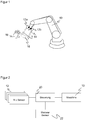
- Figure 1 shows an illustration of a robot arm 10 to be secured, which works together with an operator.
- the robot arm 10 and the special application are examples, and the following explanations can be transferred to other moving machines and scenarios to be protected, in particular AGVs / AGCs (Automated Guided Vehicles / Containers) or drones.
- AGVs / AGCs Automatic Guided Vehicles / Containers
- distance sensors 12a-b are attached to the robot arm 10, preferably in the vicinity of a tool to protect it (EOAS, end-of-arm safeguarding).
- the distance sensors 12a-b determine a number of distance values along the respective measuring beams 14.
- Optoelectronic distance sensors for example with measurement of the time of flight (ToF), are particularly suitable for this purpose.
- ToF time of flight
- the mentioned in the introduction DE 10 2015 112 656 A1 presents such a system, to which reference is made additionally.
- there are also other optoelectronic sensors to determine distances such as triangulation probes, laser scanners and 2D or 3D cameras, as well as completely different technologies, such as ultrasonic sensors, capacitive sensors, radar sensors and the like.
- the measuring beams 14 together form a virtual protective jacket 16 around the end or tool of the robot arm 10.
- the distance values measured by the distance sensors 12a-b are compared with distance thresholds during the operation of the robot arm 10. If the distance falls below a threshold, this is attributed to the intervention of a body part or other impermissible object 18.
- a safety-related reaction of the robot 10 is then triggered, which, depending on the violated distance thresholds, can consist of slowing down, evading or an emergency stop.
- the protective jacket 16 has in the example of Figure 1 the geometry of a truncated cone jacket.
- the protective jacket 16 is a surface that forms a safety-relevant access area to the robot arm 10 or its tool tip. In the example of the robot arm 10, there is in principle access from all lateral directions, so that the protective jacket 16 then preferably forms a closed surface.
- the protective jacket 16 is therefore preferably topologically a cylinder jacket, which, however, can be deformed due to the position of the measuring beams 14 in space, for example to a truncated cone, a truncated pyramid or a prism. In other applications or situations, there can also be gaps on certain pages from which a security-relevant intervention is excluded for other, in particular mechanical or structural reasons.
- the lower edge of the protective jacket 16 is defined by the distance thresholds.
- the protective jacket 16 is adapted.
- the position of the measuring beams 14 in space can be changed. Specifically, there is the possibility of shifting the origin of the measuring beams 14 and / or pivoting its alignment. This will be discussed later with reference to the Figure 3 explained in more detail.
- the length of the measuring beams 14 can be changed individually or jointly by adapting the distance thresholds, whereupon with reference to FIG Figures 4 and 5 will be entered again.
- the protective jacket 16 is to be adapted is either learned in before operation or based on it decided by sensor data depending on the situation.
- An advantageous procedure for teaching is to use certain positions of the robot arm 10 on its trajectory as switching points, for example reaching a working point at which the actual working movement begins when a workpiece is approached.
- FIG Figure 2 shows a block diagram of a security system according to the invention.
- One or more distance sensors 12 are as in FIG Figure 1 shown moved along with the machine part to be secured in order to secure it against tampering with the protective jacket 16 and thus avoid accidents and injuries.
- the distance sensors 12 are preferably optoelectronic sensors based on the time-of-flight principle, in particular based on SPAD receivers (Single-Photon Avalanche Diode), but other similar or mixed sensors from the examples given above are also conceivable.
- the distance values are passed on to a controller 20, which is responsible, among other things, for the safety evaluations considered here and which, if necessary, outputs a safe signal to the machine 10 or its controller in order to trigger a safety reaction and, for example, to adjust the working speed of the machine 10 or to stop it.
- the safety evaluations could also be accommodated in one of the distance sensors 12, but the flexibility in a controller 20 is greater.
- the separation facilitates the transfer to other systems.
- the security functionality can be implemented as a hardware component, software package, app or in any other suitable form.
- the controller 20 is preferably a safety controller, but other hardware can also be used as an alternative, such as a microcontroller, a computer, a PLC (programmable logic controller), the robot or machine controller, an edge computing infrastructure or a cloud.
- a microcontroller e.g., a central processing unit (CPU)
- a computer e.g., a central processing unit (CPU)
- PLC programmable logic controller
- the robot or machine controller e.g., a PLC (programmable logic controller) controller
- edge computing infrastructure e.g., a cloud
- the controller 20 can also receive information from the machine 10, for example positions of a robot arm, in order to identify switchover points for an adaptation of the protective jacket 16.
- at least one further sensor 22 can be connected, from whose sensor data the controller 20 determines whether the current Situation requires an adaptation of the protective jacket 16 and which new geometry is to be selected.
- the distance sensors 12 and the controller 20 must provide reliable detection and evaluation in accordance with the relevant standards.
- One way of doing this is to use safe sensors 12, 22 and a safety controller.
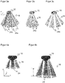
- Figure 3a shows the protective sheath 16 at the tip of the robot arm 10 in an exemplary embodiment in which a total of eight distance sensors 12 each form a sector 24a-b of the protective sheath 16 from a plurality of measuring beams 14.
- each distance sensor 12 has a series arrangement of transmitter / receiver pairs, the respective measuring beams 14 of which diverge in the shape of the sector 24a-b.
- the sector 24a-b can also be generated in each case by only one widening measuring beam 14 or at least one common illumination can be provided for a receiver line.
- the sectors 24a-b, or in general the measuring beams 14, are arranged in two or more rings. This effectively creates protective jackets 16 of different sizes arranged one inside the other.
- size means the extent in the XY direction according to the in Figure 3a Coordinate system drawn in, the Z direction of which is the center axis of the measuring beams 14 and thus essentially the direction in which the distance sensors 12 measure distances.
- the distance sensors 12 generate a large number of measuring beams 14 which together, for example, similar to a compound eye, observe an entire solid angle range around the tool tip of the robot arm 10.
- the origins of these measuring beams 14 then form a surface, and by selecting any desired closed curve on this surface, active measuring beams 14 can be selected in order to generate a specific geometry of the protective jacket 16.
- Matrix receivers of optical distance sensors 12 are particularly suitable for such an embodiment.
- the selection of a geometry then corresponds to particular regions of interest (ROI) from which the measuring beams 14 for the protective jacket 16 are recruited.
- ROI regions of interest
- the concept presented so far for adapting the geometry of the protective jacket 16 is consequently based on making more measuring beams 14 available than a protective jacket 16 needs, and among them to select those that generate a suitable geometry.
- the measuring beams 14 are pivoted jointly inwards or outwards. This changes the opening angle of the protective jacket 16 and, as a result, produces the same variation of the protective jacket as one in FIG Figures 3b-c shown selective activation of inner and outer rings.
- the Figures 4a-b illustrate a further possible adaptation of the protective jacket 16, which is now shortened or lengthened in the Z direction.
- the distance thresholds are adjusted.
- a short protective jacket 16 is created, with larger spacing thresholds as in FIG Figure 4b a longer protective sheath 16.
- the short protective sheath 16 ensures a low working speed or a situation in which the tool tip of the robot arm 10 is close to a workpiece, while the longer protective sheath 16 is activated at a higher working speed in the open space.
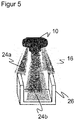
- Figure 5 illustrates an individual adaptation of the distance thresholds to a surrounding contour, here a workpiece 26. While in FIG Figure 4 the distance thresholds have been adapted together, there are now sectors 24a-b or also individual measuring beams 14 with different distance thresholds. The contour of the workpiece 26 is taught in beforehand or taken into account depending on the situation. Without individual adaptation, the workpiece 26 would either trigger an unnecessary safety reaction or leave protective gaps in areas in which the contour does not reach up far enough.
- At least one further sensor 22 detects the current situation in order to even dynamically adapt protective jacket 16 on the basis of the sensor data.
- the further sensor 22 can be part of the security system, alternatively it also has other tasks or actually belongs to another system.
- the further sensor 22, like the distance sensors 12, can be mounted on the robot arm 10 or, alternatively, in its surroundings.
- a first example of the further sensor 22 are sensors of the robot arm 10 itself. For example, depending on the direction of movement, a higher robot speed requires longer distance thresholds and / or larger diameters or opening angles of the protective jacket 16. Conclusions about the current payload can be drawn from internal current measurements at the joints of the robot arm pulled by the robot and thus the tool and workpiece moved by it can also be inferred. On the one hand, a greater load results in a greater risk potential, which requires larger protective jackets 16. On the other hand, the tool or the transported workpiece can also be identified from the weight.
- This database contains, for example, data records on possible tools or workpieces that allow a selection and thus identification from just a few properties such as weight. This means that further information can then be called up from the data record, such as the complete dimensions. Access to the manufacturer's website is also conceivable.
- the controller 20 has the option of calculating the geometry of the protective jacket 16.
- the required arithmetic rule or the partial or complete geometry including measuring beams 14 to be activated or moved and distance thresholds can be part of the data record.
- once taught-in geometries and associated sizes for certain tools, workpieces and the like can also be stored in the database in order to expand them and make them available for later use also by other security systems.
- a jaw, finger or suction gripper is possible as a tool.
- a magnetic cylinder sensor detects the piston position in pneumatic grippers, in particular whether the gripper is open or closed and thus a workpiece is present or not. The exact position of the gripper provides information about at least one dimension of the workpiece.
- An integrated gripping force measurement allows conclusions to be drawn about the weight of the workpiece; the same applies to the suction force exerted by a suction gripper.
- the further sensor 22 detects at least one property, which can then be supplemented and compared via database access in order to find a suitable geometry of the protective jacket 16 depending on the situation.
- Imaging or vision systems that is to say in particular 2D or 3D cameras, should be mentioned as a further example of the further sensor.
- Such vision systems are often available anyway so that the robot arm can solve its application and, for example, correctly grip a workpiece. However, they can also be used to adapt the protective jacket 16. If the tool and / or workpiece are at least partially in the field of vision, identification based on shape, color or contour is possible, if necessary with addition from a database access.
- the vision system it is not absolutely necessary for the vision system to recognize an object to which the protective jacket 16 is to be adapted. Independent learning is also conceivable, in which new surroundings and, in particular, changes in the environment are recognized and learning then takes place. So that it is clear that the change is intentional and not a safety-critical event, a special user input can be requested, which can also take the form of an optical marker of a newly introduced object.
- the security system, an external security system or an administrative measure must ensure that no person or part of the body is in the danger zone.
- a vision system as a further sensor 22 can also fulfill a completely different useful function, namely a safety-related system test of the protection system.
- a vision system with sensitivity in the infrared range detects the measuring beams 14 of the distance sensors 12. This enables a diverse check as to whether a measuring beam 14 has failed or has been triggered incorrectly. From the position and size of the light spots of the distance sensors 12 detected in the vision system, it is also possible to infer misalignments and to check the geometry of the protective jacket 16.
- Ident sensors are suitable as yet another example of a further sensor 22. These include RFID readers or optical code readers, but also, for example, UWB sensors (Ultra Wide Band) or magnetic identification sensors.
- the tool or workpiece is in this case with a suitable RFID transponder, Barcode, 2D code or magnetic code provided. It has already been explained above how the identity of a tool or workpiece can be used in various ways in order to determine a geometry of the adapted protective jacket 16, preferably with the support of a database. With some Ident sensors, in particular an optical code reader or a magnetic sensor in combination with a magnetic strip, positions can also be recorded very precisely if it is known where the code is attached to the tool or workpiece. This can simplify the programming of the robot arm 10.
- sensors 22 that are suitable for far-field monitoring, such as safe laser scanners, 3D cameras, printing mats and the like, may also be mentioned as further sensors.
- Such further sensors 22 do not serve directly to adapt the geometry of the protective jacket 16, but can, under certain circumstances, be used for this purpose in a dual function.
- the primary function of these additional sensors is a general monitoring of the robot arm 10, with which the application is put into an HRC-capable operating state in the first place when a worker is detected and, among other things, the safety system is activated in the process.
- maximum speed, maximum force, permitted areas of movement and the like can be established on the basis of the recordings made by these additional sensors.
Description
Die Erfindung betrifft ein Verfahren zum Absichern eines beweglichen Maschinenteils und ein Absicherungssystem für eine Maschine nach dem Oberbegriff von Anspruch 1 beziehungsweise 13.The invention relates to a method for securing a movable machine part and a securing system for a machine according to the preamble of claims 1 and 13, respectively.
Das primäre Ziel der Sicherheitstechnik ist, Personen vor Gefahrenquellen zu schützen, wie sie beispielsweise Maschinen im industriellen Umfeld darstellen. Die Maschine wird mit Hilfe von Sensoren überwacht, und wenn demnach eine Situation vorliegt, in der eine Person gefährlich nahe an die Maschine zu gelangen droht, wird eine geeignete Absicherungsmaßnahme ergriffen. In der Sicherheitstechnik eingesetzte Sensoren müssen besonders zuverlässig arbeiten und deshalb hohe Sicherheitsanforderungen erfüllen, beispielsweise die Norm EN13849 für Maschinensicherheit und die Gerätenorm IEC61496 oder EN61496 für berührungslos wirkende Schutzeinrichtungen (BWS). Zur Erfüllung dieser Sicherheitsnormen sind eine Reihe von Maßnahmen zu treffen, wie sichere elektronische Auswertung durch redundante, diversitäre Elektronik, Funktionsüberwachung oder Überwachung der Verschmutzung optischer Bauteile.The primary goal of safety technology is to protect people from sources of danger, such as those presented by machines in an industrial environment. The machine is monitored with the help of sensors, and if there is a situation in which a person threatens to get dangerously close to the machine, a suitable safety measure is taken. Sensors used in safety technology must work particularly reliably and therefore meet high safety requirements, for example the EN13849 standard for machine safety and the IEC61496 or EN61496 device standard for electro-sensitive protective devices (ESPE). To meet these safety standards, a number of measures must be taken, such as safe electronic evaluation through redundant, diverse electronics, function monitoring or monitoring of the contamination of optical components.
In der sicherheitstechnischen Überwachung von Robotern, speziell Leichtbaurobotern, besteht ein zunehmender Wunsch nach engerer Zusammenarbeit mit Personen (MRK, Mensch-Roboter-Kollaboration) auch in komplexen Umgebungen. Relevante Normen in diesem Zusammenhang sind beispielsweise die ISO 10218 für Industrieroboter oder die ISO 15066 für kollaborierende Roboter. Für solche kooperativen Anwendungen sind bisherige Sicherheitskonzepte durch Zäune und Absperrungen untauglich. Aber auch die Absicherung durch herkömmliche Sicherheitssensoren, wie Laserscanner, Lichtgitter oder Sicherheitskameras, eignet sich vorrangig für große, freie Überwachungsbereiche mit einfacher Geometrie. Ähnliche Problemstellungen ergeben sich für andere Maschinen als Roboter, beispielsweise AGVs/AGCs (Automated Guided Vehicle / Container) oder Drohnen.In the safety-related monitoring of robots, especially lightweight robots, there is an increasing desire for closer collaboration with people (HRC, human-robot collaboration), even in complex environments. Relevant standards in this context are, for example, ISO 10218 for industrial robots or ISO 15066 for collaborative robots. Previous security concepts using fences and barriers are unsuitable for such cooperative applications. However, protection using conventional safety sensors, such as laser scanners, light grids or safety cameras, is primarily suitable for large, free surveillance areas with simple geometry. Similar problems arise for machines other than robots, e.g. AGVs / AGCs (Automated Guided Vehicles / Containers) or drones.
Bei Robotern besteht ein Ansatz darin, die Kraft so zu begrenzen, dass auch eine Kollision nicht zu ernsthaften Verletzungen führen kann. Zudem wird beim Design der mechanischen Roboterkomponenten bewusst auf kantenfreie, runde oder weiche Außenkonturen geachtet. Dabei bleiben jedoch Gefahrenquellen am Werkzeug selbst, das spitze, rotierende oder heiße Teile aufweisen kann. Außerdem verhindern die mechanischen Maßnahmen und Kraftbegrenzungen Quetschungen etwa der Hand zwischen Werkzeug und einer Halterung oder dergleichen auf einer Arbeitsfläche nicht zuverlässig.One approach with robots is to limit the force so that even a collision cannot lead to serious injuries. In addition, when designing the mechanical robot components, care is taken to ensure that the outer contours are free of edges, round or soft. However, there are still sources of danger on the tool itself, which can have pointed, rotating or hot parts. In addition, the mechanical measures and force limits do not reliably prevent the hand from being crushed, for example, between the tool and a holder or the like on a work surface.
Hier besteht nun grundsätzlich die Möglichkeit, einen kleinen, leichten Distanzsensor beziehungsweise eine Mehrfachanordnung solcher Distanzsensoren mit dem Werkzeug am Roboterarm mitzubewegen. Mit einem entsprechenden Distanzsensor befasst sich die
Ein Vorteil einer derartigen Absicherung am Roboterarm ist die Verwendung bei verschiedenen Standardwerkzeugen bei nur einmaliger Investition in eine MRK-Anwendung, womit also auf die Anschaffung mehrerer teurer MRK-Überwachungsvorrichtungen verzichtet werden kann. Diese Stärke der flexiblen Einsetzbarkeit wird aber bisher dadurch beschränkt, dass jede spezifische Anwendung und jeder spezifische Prozessablauf bei der Inbetriebnahme eingelernt werden muss. Variationen im Prozess, wie etwa das Greifen verschiedener Werkstücke beziehungsweise das Greifen aus unterschiedlichen Behältern, können deshalb nur abgesichert werden, wenn von Anfang an klar definiert ist, zu welchem Zeitpunkt und an welcher Position im Prozess eine Anpassung des Schutzmantels erforderlich ist, die dann fest eingelernt wird. Außerdem sind die Möglichkeiten der Anpassung für den Schutzmantel selbst sehr begrenzt. Eine situative, flexible sicherheitsgerichtete Reaktion auf Prozess- oder Umgebungsänderungen oder andere Aktoren ist noch nicht möglich.One advantage of such a safeguard on the robot arm is the use of various standard tools with only one investment in an HRC application, which means that the acquisition of several expensive HRC monitoring devices can be dispensed with. However, this strength of the flexible applicability has so far been limited by the fact that each specific application and each specific process sequence has to be learned in during commissioning. Variations in the process, such as gripping different workpieces or gripping from different containers, can therefore only be safeguarded if it is clearly defined from the start at what point in time and at what position in the process an adjustment of the protective jacket is required, which is then fixed is taught. In addition, the possibilities of adaptation for the protective jacket itself are very limited. A situational, flexible, safety-oriented reaction to process or environmental changes or other actuators is not yet possible.
In der noch unveröffentlichten deutschen Patentanmeldung mit dem Aktenzeichen
Die noch unveröffentlichte deutsche Patentanmeldung mit dem Aktenzeichen
Aus der
Die
Die
Aus der
Vor diesem Hintergrund ist Aufgabe der Erfindung, die Absicherung einer Maschine in enger Mensch-Maschine-Kooperation zu verbessern.Against this background, the object of the invention is to improve the safeguarding of a machine in close human-machine cooperation.
Diese Aufgabe wird durch ein Verfahren zum Absichern eines beweglichen Maschinenteils und ein Absicherungssystem für eine Maschine nach Anspruch 1 beziehungsweise 13 gelöst. Die Maschine ist insbesondere ein Roboter oder Roboterarm mit einem Werkzeug, das vornehmlich abzusichern ist (EOAS, End-of-Arm-Safeguarding). Dieses Anwendungsbeispiel eines Roboters wird im Folgenden vielfach stellvertretend verwendet, die Erläuterungen sind jeweils analog auf ein anderes bewegliches Maschinenteil zu übertragen. Die Absicherung erfolgt durch Überwachung eines virtuellen Schutzmantels um zumindest einen Teil des beweglichen Maschinenteils auf Eingriffe durch Objekte, die dann zu einer sicherheitsgerichteten Reaktion der Maschine führen. Dabei muss nicht jedes eingreifende Objekt sofort die sicherheitsgerichtete Reaktion auslösen, beispielsweise können kleine Objekte oder ganz kurze Eingriffe toleriert werden.This object is achieved by a method for securing a movable machine part and a securing system for a machine according to claims 1 and 13, respectively. The machine is in particular a robot or robot arm with a tool that is primarily to be secured (EOAS, end-of-arm safeguarding). This application example of a robot is often used as a representative in the following, the explanations are to be transferred analogously to another movable machine part. Protection takes place by monitoring a virtual protective jacket around at least part of the moving machine part for interference by objects, which then lead to a safety-related reaction of the machine. Not every intervening object has to immediately trigger the safety-related reaction; for example, small objects or very brief interventions can be tolerated.
Der Schutzmantel wird von den Messstrahlen mindestens eines mit dem Maschinenteil mitbewegten berührungslosen Distanzsensors erzeugt, der insbesondere an dem Maschinenteil in der Nähe oder Umgebung eines Werkzeugs angebracht und vorzugsweise ein optoelektronischer Distanzsensor ist. Um mehrere Messstrahlen mit jeweiliger Messung von Abstandswerten zu erhalten, sind mehrere Distanzsensoren vorgesehen und/oder ein Distanzsensor weist mehrere Messstrahlen auf. Die Geometrie des Schutzmantels setzt sich aus den Messstrahlen und somit deren Lage im Raum zusammen. Diese Lage wird hier über Ursprung und Ausrichtung des jeweiligen Messstrahls definiert, was wiederum durch Position und Orientierung des mindestens einen Distanzsensors bestimmt ist. Die Länge des Schutzmantels lässt sich durch gemeinsame oder individuelle Abstandsschwellen der Messstrahlen einstellen.The protective jacket is generated by the measuring beams of at least one contactless distance sensor that moves along with the machine part, which is attached in particular to the machine part in the vicinity of or in the vicinity of a tool and is preferably an optoelectronic distance sensor. In order to obtain several measuring beams with respective measurement of distance values, several distance sensors are provided and / or a distance sensor has several measuring beams. The geometry of the protective jacket is made up of the measuring beams and thus their position in space. This position is defined here via the origin and alignment of the respective measuring beam, which in turn is determined by the position and orientation of the at least one distance sensor. The length of the protective jacket can be adjusted using common or individual distance thresholds for the measuring beams.
Die Erfindung geht von dem Grundgedanken aus, den Schutzmantel durch Veränderung der Lage der Messstrahlen im Raum anzupassen. Dazu können Ursprung und/oder Ausrichtung von einem, mehreren oder allen Messstrahlen verändert werden. Gemeint ist der effektive Ursprung der schützenden Messstrahlen, beispielsweise auch nach Spiegelung an einem insbesondere beweglichen Spiegelelement wie einem MEMS-Spiegel. Bezugssystem ist dabei das bewegliche Maschinenteil, die ständigen Änderungen der Lage der Messstrahlen zur Umgebung aufgrund der Bewegung des Maschinenteils und des mitbewegten Distanzsensors sind keine Anpassung desThe invention is based on the basic idea of adapting the protective jacket by changing the position of the measuring beams in space. For this purpose, the origin and / or alignment of one, several or all of the measuring beams can be changed. What is meant is the effective origin of the protective measuring beams, for example also after reflection on a particularly movable mirror element such as a MEMS mirror. The reference system is the moving machine part; the constant changes in the position of the measuring beams in relation to the environment due to the movement of the machine part and the distance sensor that moves with it are not an adaptation of the
Schutzmantels. Hier und im Folgenden wird öfter ein mitbewegtes Bezugssystem verwendet, dessen Z-Achse im Wesentlichen der Richtung der Messstrahlen entspricht. Da die Messstrahlen nicht notwendig parallel zueinander verlaufen, wird eine gemeinsame Z-Achse beispielsweise als Mittelachse der Messstrahlen definiert. Die erfindungsgemäßen Anpassungen der Messstrahlen betreffen die lateralen Richtungen quer zu der Z-Achse, also eine Veränderung in X- oder Y-Richtung mit zu der Z-Achse senkrechten X- und Y-Achsen. Der Schutzmantel wird dadurch zumindest lokal breiter oder enger.Protective sheath. Here and in the following, a moving reference system is often used, the Z-axis of which essentially corresponds to the direction of the measuring beams. Since the measuring beams do not necessarily run parallel to one another, a common Z-axis is defined, for example, as the central axis of the measuring beams. The adaptations according to the invention of the measuring beams relate to the lateral directions transverse to the Z axis, that is to say a change in the X or Y direction with the X and Y axes perpendicular to the Z axis. The protective jacket is thereby at least locally wider or narrower.
Die Erfindung hat den Vorteil, dass die Absicherung intelligenter und flexibler werden kann. Es gibt somit noch mehr Einsatzmöglichkeiten. Das Eingreifen eines Werkers bei Veränderungen der Anwendung oder in der Anwendung beziehungsweise der Umgebung oder dem Prozess ist nicht erforderlich, die Anpassung erfolgt automatisch, selbst wenn nicht im Vorfeld bekannt ist, zu welchem Zeitpunkt oder an welchem Ort welche Anpassung notwendig ist. Der manuelle Integrationsaufwand wird minimiert und zugleich Sicherheit und Verfügbarkeit maximiert. So wird die Produktivität gesteigert, und die Sicherheitsfunktion bleibt stets gewährleistet.The invention has the advantage that the protection can become more intelligent and flexible. There are thus even more possible uses. The intervention of a worker in the event of changes in the application or in the application or the environment or the process is not required, the adaptation takes place automatically, even if it is not known in advance at what point in time or where which adaptation is necessary. The manual integration effort is minimized and at the same time security and availability are maximized. This increases productivity and the safety function is always guaranteed.
Der Schutzmantel weist vorzugsweise die Geometrie eines Zylinders, Kegelstumpfes, Prismas oder Pyramidenstumpfes auf. Die jeweils als Stumpf ausgebildeten Geometrien haben den Vorteil, dass sich der Schutzmantel aufweitet und somit nicht auf die Dimensionen der Anordnung der Distanzsensoren festgelegt ist. Die Spitze dieser Körper ist deshalb abgeschnitten, weil dort das Maschinenteil oder der stumpfe und ungefährliche hintere Teil von dessen Werkzeug angeordnet ist. Die Deckfläche an der abgeschnittenen Spitze wird von den Ursprüngen der Messstrahlen umrandet, und zwar kreisförmig im Falle eines Kegelstumpfes und mit einem regelmäßigen oder unregelmäßigen Vieleck bei einem Pyramidenstumpf.The protective jacket preferably has the geometry of a cylinder, truncated cone, prism or truncated pyramid. The geometries that are each designed as a stump have the advantage that the protective jacket expands and is therefore not restricted to the dimensions of the arrangement of the distance sensors. The tip of this body is cut off because the machine part or the blunt and harmless rear part of its tool is arranged there. The top surface at the cut tip is bordered by the origins of the measuring beams, namely circular in the case of a truncated cone and with a regular or irregular polygon in the case of a truncated pyramid.
Vorzugsweise wird der Öffnungswinkel und/oder der Durchmesser des Schutzmantels verändert. Dadurch wird der Schutzmantel in der lateralen Richtung, die oben als X-Y-Richtung definiert wurde, größer oder kleiner. Werden dabei die Ursprünge verschoben, so verändert sich der Durchmesser des Schutzmantels in einer radialen Streckung. Eine Änderung des Öffnungswinkels dehnt oder staucht den Schutzmantel im Bereich der Ursprünge noch nicht, sondern erst linear zunehmend zum fernen Rand hin.The opening angle and / or the diameter of the protective jacket is preferably changed. As a result, the protective jacket becomes larger or smaller in the lateral direction, which was defined above as the XY direction. If the origins are shifted in the process, the diameter of the protective jacket changes in a radial expansion. A change in the opening angle does not stretch or compress the protective jacket in the area of the origins, but only increases linearly towards the distant edge.
Der Schutzmantel wird bevorzugt aus mehreren Sektoren je eines von mehreren Distanzsensoren mit einer Reihe von Messstrahlen aufgespannt. Der einzelne Distanzsensor erzeugt also mit nebeneinanderliegenden Messstrahlen eine Fläche, die den Sektor bildet. Dazu ist beispielsweise ein optoelektronischer Distanzsensor mit einer Empfängerzeile geeignet. Die Messstrahlen eines einzelnen Distanzsensors können parallel zueinander liegen oder auseinanderlaufen, dementsprechend wird der Sektor dann rechteckig oder dreieckig.The protective jacket is preferably spanned from several sectors, each one of several distance sensors with a number of measuring beams. The individual distance sensor thus generates a surface with adjacent measuring beams that forms the sector. For example, an optoelectronic distance sensor with a receiver line is suitable for this purpose. The measuring beams of an individual distance sensor can lie parallel to one another or diverge from one another, and the sector then becomes rectangular or triangular accordingly.
Die Anpassung des Schutzmantels erfolgt in einer ersten Alternative des Anspruchs 1 dadurch, dass andere Messstrahlen aktiviert werden, insbesondere durch Wahl eines interessierenden Bereichs des Distanzsensors. Die Distanzsensoren können in dieser Ausführungsform mehr Messstrahlen erzeugen als für einen Schutzmantel benötigt. Eine andere Auswahl der aktiven Messstrahlen ändert damit die Geometrie des Schutzmantels. Bei einem optoelektronischen Distanzsensor mit einer Vielzahl von entfernungsmessenden Lichtempfangselementen, etwa mit einer TOF-Zeile oder TOF-Matrix (Time of Flight, Lichtlaufzeitverfahren), können dazu interessierende Bereiche (ROI, Region of Interest) definiert und verändert werden.In a first alternative of claim 1, the protective jacket is adapted in that other measuring beams are activated, in particular by selecting a region of interest of the distance sensor. In this embodiment, the distance sensors can generate more measuring beams than are required for a protective jacket. A different selection of the active measuring beams thus changes the geometry of the protective jacket. In the case of an optoelectronic distance sensor with a large number of distance-measuring light receiving elements, for example with a TOF line or TOF matrix (time of flight, time of flight method), areas of interest (ROI, region of interest) can be defined and changed for this purpose.
Die Ursprünge der Messstrahlen bilden bevorzugt mindestens zwei partielle oder vollständige Ringe oder Vielecke, die selektiv aktiviert werden. Solche Ringe oder Vielecke bilden vorzugsweise, aber nicht notwendig eine geschlossene Linie. Es sind auch Halbkreise oder andere Segmente vorstellbar, etwa wenn nur die Bewegung der Maschine in einer bestimmten, bekannten Richtung abgesichert werden soll. In einer Anordnung der Messstrahlen mit zwei vollständigen oder teilweisen Ringen oder Vielecken sind gleichsam zwei oder noch mehr Schutzmäntel ineinander verschachtelt. Bei einer Ringanordnung sind die Schutzmäntel kegelstumpfförmig oder zylindrisch, bei einem Vieleck entsprechend pyramidenstumpfförmig oder prismatisch. Je nach Bedarf wird ein weiter innen oder weiter außen liegender und damit kleinerer oder größerer Schutzmantel aktiviert. Es ist auch denkbar, mehrere der Schutzmäntel zugleich zu verwenden, wobei dann insbesondere der äußere Schutzmantel als Warnfeld mit einer schwächeren Sicherheitsmaßnahme wie einem Alarm oder einer gewissen Geschwindigkeitsreduktion und erst der innere Schutzmantel als Schutzfeld mit einer echten Absicherung durch Anhalten, Ausweichen oder starke Geschwindigkeitsreduktion fungieren kann.The origins of the measuring beams preferably form at least two partial or complete rings or polygons which are selectively activated. Such rings or polygons preferably, but not necessarily, form a closed line. Semicircles or other segments are also conceivable, for example if only the movement of the machine in a certain, known direction is to be safeguarded. In an arrangement of the measuring beams with two complete or partial rings or polygons, two or even more protective jackets are nested in one another. In the case of a ring arrangement, the protective sheaths are frustoconical or cylindrical, in the case of a polygon they are correspondingly truncated pyramidal or prismatic. Depending on requirements, a protective jacket that is further inside or further outside, and thus smaller or larger, is activated. It is also conceivable to use several of the protective sheaths at the same time, in which case the outer protective sheath in particular acts as a warning field with a weaker safety measure such as an alarm or a certain speed reduction, and only the inner protective sheath as a protective field with real protection by stopping, evasive or strong speed reduction can.
Die Anpassung des Schutzmantels erfolgt in einer zweiten Alternative des Anspruchs 1 durch Bewegen oder Schwenken des Distanzsensors. Diese Anpassung wird durch physische Bewegung und Einwirken eines Motors oder sonstigen Aktors bewirkt. Eine Bewegung verschiebt den Ursprung mindestens eines Messstrahls, sei es durch bewegliche Elemente in einem Distanzsensor oder einen insgesamt beweglichen Distanzsensor. Durch Schwenken wird die Ausrichtung verändert. Dabei kann auch ein Spiegelelement verschwenkt oder bewegt werden, insbesondere ein MEMS-Spiegel. Insbesondere werden dabei alle Messstrahlen nach innen oder außen geneigt und verkleinern oder vergrößern auf diese Weise den Öffnungswinkel des Schutzmantels. Es sei nochmals daran erinnert, dass Bewegen und Schwenken jeweils in einem mit dem Maschinenteil mitbewegten Bezugssystem gemeint ist.In a second alternative of claim 1, the protective jacket is adapted by moving or pivoting the distance sensor. This adaptation is brought about by physical movement and the action of a motor or other actuator. A movement shifts the origin of at least one measuring beam, be it through movable elements in a distance sensor or a distance sensor that is movable as a whole. Panning changes the orientation. A mirror element can also be pivoted or moved, in particular a MEMS mirror. In particular, all measuring beams are inclined inwards or outwards and in this way reduce or enlarge the opening angle of the protective jacket. It should be remembered again that moving and pivoting are each meant in a reference system that moves along with the machine part.
Der Schutzmantel wird bevorzugt zumindest in Teilbereichen durch Veränderung der Abstandsschwellen angepasst. Das ist eine Anpassung des Schutzmantels in einer weiteren Dimension, nämlich der Z-Richtung im oben definierten mitbewegten Koordinatensystem. Anschaulich wird der Schutzmantel länger oder kürzer, nicht breiter oder schmaler, wobei das auch miteinander kombinierbar ist. Eine globale Anpassung aller Abstandsschwellen erfolgt beispielsweise in Abhängigkeit von der Bewegungsgeschwindigkeit des Maschinenteils oder der Gefahr, die von einem bestimmten Werkzeug ausgeht. Werden die Abstandsschwellen nicht gemeinsam in gleicher Weise verändert, so ist auch eine Anpassung an eine bestimmte Z-Kontur möglich, etwa für ein neues zu bearbeitendes oder zu greifendes Werkstück.The protective jacket is preferably adapted at least in partial areas by changing the distance thresholds. This is an adaptation of the protective jacket in a further dimension, namely the Z direction in the coordinate system defined above. The protective jacket is clearly longer or shorter, not wider or narrower, and these can also be combined with one another. A global adjustment of all distance thresholds takes place, for example, as a function of the speed of movement of the machine part or the danger posed by a specific tool. If the distance thresholds are not changed together in the same way, an adaptation to a specific Z-contour is also possible, for example for a new workpiece to be machined or gripped.
Vorzugsweise wird mit mindestens einem weiteren Sensor eine Eigenschaft des beweglichen Maschinenteils, eines Werkzeugs am Maschinenteil oder eines mitgeführten oder bearbeiteten Werkstücks oder dessen Umgebung erfasst, wobei der Schutzmantel anhand der erfassten Eigenschaft angepasst wird. Dabei kann ein Werkstück eng als ein eigentliches Werkstück aufgefasst werden, aber auch insbesondere im Zusammenhang mit der Erfassung von dessen Umgebung breiter verstanden werden und beispielsweise eine Arbeitsposition, einen Werkzeugträger oder Werkstückhalter, einen Behälter mit zu greifenden Objekten und dergleichen mit umfassen. Der weitere Sensor kann ein bereits für die Maschine vorhandener Sensor sein, der aber primär andere Aufgaben erfüllt und nun für das Absicherungssystem mitgenutzt wird.A property of the movable machine part, a tool on the machine part or a workpiece that is carried or processed or its surroundings is preferably detected with at least one further sensor, the protective jacket being adapted on the basis of the detected property. A workpiece can be understood narrowly as an actual workpiece, but can also be understood more broadly, in particular in connection with the detection of its surroundings and include, for example, a work position, a tool carrier or workpiece holder, a container with objects to be gripped and the like. The additional sensor can be a sensor that is already available for the machine, but which primarily fulfills other tasks and is now also used for the safety system.
Der weitere Sensor liefert über die Eigenschaft die Information, wie die Anpassung des Schutzmantels erfolgen soll. Das sind beispielsweise Prozesszustände, Prozessvariationen, Abmessungen von Werkzeug und/oder Werkstück, eine Position des Maschinenteils, insbesondere Erreichen eines Umschaltpunkts, oder eine Geschwindigkeit des Maschinenteils. Zur Anpassung können feste Werte für den angepassten Schutzmantel oder Rechenvorschriften zu deren Gewinnung in einer Datenbank abgelegt sein, auf die lokal oder auch beispielsweise per Cloud zugegriffen wird. Der weitere Sensor ist intern oder extern und kann an der Maschine und insbesondere dem beweglichen Maschinenteil oder in dessen Umgebung montiert sein.The other sensor provides the information about the property as to how the protective jacket is to be adapted. These are, for example, process states, process variations, Dimensions of the tool and / or workpiece, a position of the machine part, in particular reaching a switchover point, or a speed of the machine part. For adaptation, fixed values for the adapted protective jacket or calculation rules for obtaining them can be stored in a database, which can be accessed locally or, for example, via the cloud. The further sensor is internal or external and can be mounted on the machine and in particular the moving machine part or in its vicinity.
Das bewegte Maschinenteil weist bevorzugt einen Greifer auf, und der weitere Sensor bestimmt als Eigenschaft, ob der Greifer geöffnet oder geschlossen ist oder mit welcher Greifkraft ein Werkstück gehalten wird. Dabei kann es sich um einen Greifer mit integriertem weiterem Sensor handeln, der beispielsweise die Greifkraft oder Greiferposition misst, wie ein Magnetsensor für die Kolbenposition in pneumatischen Greifern. Ein offener Greifer trägt kein Werkstück, ein geschlossener in der Regel schon, vor allem wenn noch eine gewisse Greifkraft ausgeübt wird. Es ist sogar denkbar, das Werkstück anhand des aus der erforderlichen Greifkraft oder direkt bestimmten Gewichts zu identifizieren und anhand der Identität aus einer Datenbank weitere Informationen zu dem Werkstück zu gewinnen. Der Greifer kann als Sauggreifer mit entsprechender Saugkraft ausgebildet sein.The moving machine part preferably has a gripper, and the further sensor determines as a property whether the gripper is open or closed or with what gripping force a workpiece is held. This can be a gripper with an integrated additional sensor that measures, for example, the gripping force or gripper position, like a magnetic sensor for the piston position in pneumatic grippers. An open gripper does not carry a workpiece, a closed one usually does, especially if a certain gripping force is still being exerted. It is even conceivable to identify the workpiece on the basis of the weight determined from the required gripping force or directly and to obtain further information on the workpiece on the basis of the identity from a database. The gripper can be designed as a suction gripper with a corresponding suction force.
Der weitere Sensor ist vorzugsweise ein bildgebender Sensor, und als Eigenschaft wird mittels Bildverarbeitung das Werkzeug und/oder das Werkstück vermessen oder identifiziert. Ein bildgebender Sensor erfasst sehr viele Informationen zur aktuellen Situation, aus denen die für die Anpassung des Schutzmantels maßgebliche Eigenschaft gewonnen werden kann. Für die Objektvermessung und Objekterkennung stehen unzählige an sich bekannte Bildverarbeitungsverfahren zur Verfügung. In einer vorteilhaften Ausprägung wird die Bewegung des Maschinenteils genutzt, um mit dem daran angebrachten weiteren Sensor das Werkzeug und/oder Werkstück aus mehreren Perspektiven aufzunehmen, insbesondere eine 3D-Vermessung vorzunehmen, und dementsprechend den Schutzmantel noch genauer und der Situation angemessen anzupassen.The further sensor is preferably an imaging sensor, and the tool and / or the workpiece is measured or identified as a property by means of image processing. An imaging sensor records a great deal of information about the current situation, from which the property that is decisive for the adaptation of the protective jacket can be obtained. Countless image processing methods known per se are available for object measurement and object recognition. In an advantageous embodiment, the movement of the machine part is used to record the tool and / or workpiece from several perspectives with the additional sensor attached to it, in particular to carry out a 3D measurement, and accordingly to adapt the protective jacket more precisely and appropriately to the situation.
Der weitere Sensor prüft vorzugsweise den Schutzmantel. Beispielsweise kann ein bildgebender Sensor prüfen, ob längs der Messstrahlen noch Licht insbesondere im Infrarotbereich ausgesandt wird. Damit wird das Sicherheitsniveau der Distanzsensoren beziehungsweise der gesamten Absicherung weiter erhöht.The further sensor preferably checks the protective jacket. For example, an imaging sensor can check whether light is still being emitted along the measuring beams, in particular in the infrared range. This further increases the security level of the distance sensors and the entire protection.
Der weitere Sensor erkennt das Werkzeug oder Werkstück bevorzugt anhand einer Identitätsmarke, insbesondere einem RFID-Transponder, einem UWB-Tag (Ultra Wide Band), einem Barcode oder einer Magnetcodierung, und die Eigenschaft wird aus der erkannten Identität abgeleitet. Damit werden Werkzeug beziehungsweise Werkstück sehr verlässlich identifiziert. Es kann eine Datenbank vorbereitet werden, in der notwendige Geometrien für jeweils geeignete Schutzmäntel abgelegt sind und auf die lokal oder per Netzwerk gezielt anhand der Identität zugegriffen wird. Die Datenbank kann sowohl helfende Größen und Rechenvorschriften als auch fertigen Ursprungspositionen, Ausrichtungen und gegebenenfalls Abstandsschwellen bereitstellen.The further sensor recognizes the tool or workpiece preferably on the basis of an identity mark, in particular an RFID transponder, a UWB (Ultra Wide Band) tag, a barcode or a magnetic coding, and the property is derived from the recognized identity. This allows the tool or workpiece to be identified very reliably. A database can be prepared in which the necessary geometries are stored for suitable protective jackets and which can be accessed locally or via network in a targeted manner based on the identity. The database can provide both helpful variables and calculation rules as well as finished original positions, alignments and, if necessary, distance thresholds.
Der Distanzsensor ist bevorzugt ein sicherer Sensor und/oder die Funktionsfähigkeit des Distanzsensors wird zyklisch überprüft und/oder die Abstandswerte mehrerer Distanzsensoren werden zur Erzeugung sicherer Abstandswerte untereinander verglichen. Es werden also sichere Abstandswerte gewonnen. Dabei kann der Distanzsensor schon selbst normgerecht ausgebildet sein. Sicherheit kann auch durch mehrere redundante und/oder diversitär redundante Distanzsensoren beziehungsweise zyklische Funktionstests hergestellt werden, oder es wird auf diesem Weg ein höheres Sicherheitsniveau erreicht.The distance sensor is preferably a safe sensor and / or the functionality of the distance sensor is checked cyclically and / or the distance values of several distance sensors are compared with one another in order to generate safe distance values. Safe distance values are therefore obtained. The distance sensor itself can be designed to conform to standards. Safety can also be established by several redundant and / or diversely redundant distance sensors or cyclic function tests, or a higher level of safety is achieved in this way.
In vorteilhafter Weiterbildung ist ein Absicherungssystem für eine Maschine mit einem beweglichen Maschinenteil vorgesehen, wobei das Absicherungssystem mindestens einen berührungslosen Distanzsensor sowie eine Steuer- und Auswertungseinheit zum Ausführen eines erfindungsgemäßen Verfahrens aufweist. Dabei ist die Auswertungsfunktionalität vorzugsweise nicht im Sensor selbst implementiert, sondern in einem daran angeschlossenen System wie einer Sicherheitssteuerung oder auch einer nicht sicheren Steuerung oder sonstigen Recheneinheit, die dann durch Redundanz oder Tests abgesichert wird. Die Implementierung außerhalb des Distanzsensors erleichtert die Aktualisierung und Anpassung an andere Anwendungen.In an advantageous development, a protection system for a machine with a movable machine part is provided, the protection system having at least one contactless distance sensor and a control and evaluation unit for carrying out a method according to the invention. The evaluation functionality is preferably not implemented in the sensor itself, but in a system connected to it, such as a safety controller or a non-safe controller or other computing unit, which is then secured by redundancy or tests. Implementation outside of the distance sensor makes it easier to update and adapt to other applications.
Vorzugsweise ist mindestens ein weiterer Sensor vorgesehen, der in Kommunikationsverbindung mit der Steuer- und Auswertungseinheit steht, um eine Eigenschaft des beweglichen Maschinenteils, eines Werkzeugs am Maschinenteil oder eines mitgeführten oder bearbeiteten Werkstücks zu erfassen und anhand der Eigenschaft den Schutzmantel anzupassen. Mögliche Ausgestaltungen und Verwendungen des weiteren Sensors sowie das Verständnis des Begriffs Werkstück wurden oben schon beschrieben.At least one additional sensor is preferably provided which is in communication with the control and evaluation unit in order to detect a property of the movable machine part, a tool on the machine part or a workpiece carried or processed and to adapt the protective jacket based on the property. Possible configurations and uses of the further sensor and the understanding of the term workpiece have already been described above.
Das erfindungsgemäße Verfahren kann auf ähnliche Weise weitergebildet werden und zeigt dabei ähnliche Vorteile. Derartige vorteilhafte Merkmale sind beispielhaft, aber nicht abschließend in den sich an die unabhängigen Ansprüche anschließenden Unteransprüchen beschrieben.The method according to the invention can be developed in a similar way and shows similar advantages. Such advantageous features are described by way of example, but not conclusively, in the subclaims that follow the independent claims.
Die Erfindung wird nachstehend auch hinsichtlich weiterer Merkmale und Vorteile beispielhaft anhand von Ausführungsformen und unter Bezug auf die beigefügte Zeichnung näher erläutert. Die Abbildungen der Zeichnung zeigen in:
- Fig. 1
- eine Darstellung eines mit einem Schutzmantel abgesicherten Roboterarms;
- Fig. 2
- eine Blockdarstellung eines Absicherungssystems mit mindestens einem Distanzsensor;
- Fig. 3a
- eine dreidimensionale Darstellung eines inneren und äußeren Schutzmantels;
- Fig. 3b
- eine dreidimensionale Darstellung einer ersten Anpassung des Schutzmantels durch Aktivierung des inneren Schutzmantels;
- Fig. 3c
- eine dreidimensionale Darstellung einer zweiten Anpassung des Schutzmantels durch Aktivierung des äußeren Schutzmantels;
- Fig. 4a
- eine dreidimensionale Darstellung eines Schutzmantels mit kurzen Abstandsschwellen;
- Fig. 4b
- eine dreidimensionale Darstellung eines Schutzmantels mit langen Abstandsschwellen; und
- Fig. 5
- eine dreidimensionale Darstellung eines Schutzmantels mit individuellen Abstandsschwellen zur Anpassung an eine Werkstückkontur.
- Fig. 1
- a representation of a secured with a protective sheath robot arm;
- Fig. 2
- a block diagram of a protection system with at least one distance sensor;
- Fig. 3a
- a three-dimensional representation of an inner and outer protective jacket;
- Figure 3b
- a three-dimensional representation of a first adaptation of the protective jacket by activating the inner protective jacket;
- Figure 3c
- a three-dimensional representation of a second adaptation of the protective jacket by activating the outer protective jacket;
- Figure 4a
- a three-dimensional representation of a protective jacket with short distance thresholds;
- Figure 4b
- a three-dimensional representation of a protective jacket with long distance sleepers; and
- Fig. 5
- a three-dimensional representation of a protective jacket with individual distance thresholds for adaptation to a workpiece contour.
Zur Absicherung sind an dem Roboterarm 10 Distanzsensoren 12a-b angebracht, vorzugsweise in der Umgebung eines Werkzeugs zu dessen Absicherung (EOAS, End-of-Arm-Safeguarding). Die Distanzsensoren 12a-b bestimmen mehrere Abstandswerte längs jeweiliger Messstrahlen 14. Dazu eignen sich besonders optoelektronische Abstandssensoren beispielsweise mit Messung der Lichtlaufzeit (ToF, Time of Flight). Die einleitend genannte
Die Messstrahlen 14 bilden gemeinsam einen virtuellen Schutzmantel 16 um das Ende beziehungsweise Werkzeug des Roboterarms 10. Dazu werden während des Betriebs des Roboterarms 10 die von den Distanzsensoren 12a-b gemessenen Abstandswerte mit Abstandsschwellen verglichen. Ist eine Abstandsschwelle unterschritten, so wird das auf den Eingriff eines Körperteils oder sonstigen unzulässigen Objekts 18 zurückgeführt. Dann wird eine sicherheitsgerichtete Reaktion des Roboters 10 ausgelöst, die abhängig von den verletzten Abstandsschwellen in einem Verlangsamen, Ausweichen oder einem Nothalt bestehen kann.The measuring beams 14 together form a virtual
Der Schutzmantel 16 hat im Beispiel der
Erfindungsgemäß wird der Schutzmantel 16 angepasst. Dazu kann einerseits die Lage der Messstrahlen 14 im Raum verändert werden. Konkret besteht dazu die Möglichkeit, den Ursprung der Messstrahlen 14 zu verschieben und/oder dessen Ausrichtung zu verschwenken. Dies wird später unter Bezugnahme auf die
Die Abstandswerte werden an eine Steuerung 20 weitergegeben, die unter anderem für die hier betrachteten Sicherheitsauswertungen zuständig ist und die erforderlichenfalls ein sicheres Signal an die Maschine 10 beziehungsweise deren Steuerung ausgibt, um eine Sicherheitsreaktion auszulösen und beispielsweise die Arbeitsgeschwindigkeit der Maschine 10 anzupassen oder diese anzuhalten. Prinzipiell könnten die Sicherheitsauswertungen auch in einem der Distanzsensoren 12 untergebracht sein, aber die Flexibilität in einer Steuerung 20 ist größer. Außerdem erleichtert die Trennung die Übertragung auf andere Systeme. Die Sicherheitsfunktionalität kann als Hardwarebaustein, Softwarepaket, App oder in jeder sonst geeigneten Form implementiert sein. Die Steuerung 20 ist vorzugsweise eine Sicherheitssteuerung, alternativ kommt aber auch eine andere Hardware in Betracht, wie ein Mikrocontroller, ein Computer, ein PLC (programmable logic controller), die Roboter- oder Maschinensteuerung, eine Edge-Computing-Infrastruktur oder eine Cloud. Auch hinsichtlich der Kommunikationsverbindungen besteht eine große Auswahl, etwa I/O-Link, Bluetooth, WLAN, Wi-Fi, 3G/4G/5G und prinzipiell jeglicher industrietauglicher Standard.The distance values are passed on to a
Die Steuerung 20 kann auch Informationen der Maschine 10 empfangen, beispielsweise Positionen eines Roboterarms, um Umschaltpunkte für eine Anpassung des Schutzmantels 16 zu erkennen. Außerdem kann mindestens ein weiterer Sensor 22 angeschlossen sein, aus dessen Sensordaten die Steuerung 20 bestimmt, ob die gegenwärtige Situation eine Anpassung des Schutzmantels 16 erfordert und welche neue Geometrie zu wählen ist.The
Die Distanzsensoren 12 und die Steuerung 20 müssen eine sichere Erfassung und Auswertung im Sinne der einschlägigen Normen leisten. Ein Weg dafür ist, dass sichere Sensoren 12, 22 und eine Sicherheitssteuerung eingesetzt werden. Es ist aber auch denkbar, originär nicht sichere Hardware zu verwenden und das geforderte Sicherheitsniveau durch Redundanz, auch diversitäre Redundanz, beziehungsweise Plausibilitätschecks oder zyklische Tests zu erreichen.The
Die Sektoren 24a-b, oder allgemein die Messstrahlen 14, sind zu zwei oder mehr Ringen angeordnet. Dadurch entstehen effektiv ineinander angeordnete Schutzmäntel 16 unterschiedlicher Größe. Hier bedeutet Größe die Ausdehnung in der X-Y-Richtung gemäß dem in
Um die Geometrie des Schutzmantels 16 anzupassen, besteht nun die Möglichkeit, wahlweise nur den inneren Ring der Sektoren 24a wie in
In Erweiterung dieses Gedankens kann man sich auch vorstellen, dass die Distanzsensoren 12 eine Vielzahl von Messstrahlen 14 erzeugen, die gemeinsam beispielsweise ähnlich einem Facettenauge einen ganzen Raumwinkelbereich um die Werkzeugspitze des Roboterarms 10 beobachten. Die Ursprünge dieser Messstrahlen 14 bilden dann eine Fläche, und durch Auswahl einer beliebigen geschlossenen Kurve auf dieser Fläche lassen sich aktive Messstrahlen 14 selektieren, um eine bestimmte Geometrie des Schutzmantels 16 zu erzeugen. Für eine solche Ausführungsform eigenen sich besonders Matrixempfänger von optischen Distanzsensoren 12. Die Auswahl einer Geometrie entspricht dann besonderen interessierenden Bereichen (ROI, region of interest), aus denen die Messstrahlen 14 für den Schutzmantel 16 rekrutiert werden. Die Besonderheit ist, dass diese ROIs gemeinsam vorzugsweise eine geschlossene Kurve bilden.As an extension of this idea, one can also imagine that the
Das bisher vorgestellte Konzept zur Anpassung der Geometrie des Schutzmantels 16 basiert folglich darauf, mehr Messstrahlen 14 zur Verfügung zu stellen, als ein Schutzmantel 16 benötigt, und darunter diejenigen auszuwählen, die eine geeignete Geometrie erzeugen. Alternativ oder ergänzend ist auch möglich, die Lage von Messstrahlen 14 im Raum zu manipulieren. Es ist dann mindestens ein Aktor oder Motor vorhanden, der einen Distanzsensor als Ganzes oder einen Teil davon, der mindestens einen Messstrahl 14 erzeugt, verschiebt oder verkippt. Als besonders bevorzugter Spezialfall werden die Messstrahlen 14 gemeinsam nach innen oder außen verschwenkt. Das verändert den Öffnungswinkel des Schutzmantels 16 und erzeugt im Ergebnis dieselbe Variation des Schutzmantels wie eine in den
Die
Es besteht somit in Zusammenfassung der bisherigen Erläuterungen die Möglichkeit, den Schutzmantel 16 durch verschiedenste Veränderungen der Lage von Messstrahlen 14 im Raum in der X-Y-Richtung und/oder durch Veränderung der Abstandsschwellen in der Z-Richtung anzupassen. Dadurch ist bereits eine hohe Flexibilität erreicht, um geeignete Schutzmäntel für verschiedene Anwendungen und Anwendungssituationen einzulernen, beispielsweise an Umschaltpunkten innerhalb des Arbeitsablaufs.In summary of the previous explanations, there is thus the possibility of adapting the
Eine noch größere Flexibilität lässt sich dadurch erreichen, dass mindestens ein weiterer Sensor 22 die aktuelle Situation erfasst, um den Schutzmantel 16 auf Basis der Sensordaten sogar dynamisch anzupassen. Der weitere Sensor 22 kann Teil des Absicherungssystems sein, alternativ hat er auch noch andere Aufgaben oder gehört eigentlich zu einem anderen System. Ebenso kann der weitere Sensor 22 wie die Distanzsensoren 12 an dem Roboterarm 10 oder alternativ in dessen Umgebung montiert sein.Even greater flexibility can be achieved in that at least one
Eine intelligente und situationsgerechte Anpassung des Schutzmantels 16 garantiert stets die Sicherheitsfunktion und wählt zugleich den Schutzmantel 16 in allen Richtungen so klein wie möglich. Dazu im Gegensatz mussten bisher worst-case-Szenarien abgebildet werden, die zu unnötig großen Schutzmänteln 16 führen, mit zahlreichen unerwünschten Konsequenzen wie zu frühes Abschalten oder Verlangsamen des Roboterarms 10, überflüssige Umschaltprozesse beim Annähern oder Nichterreichbarkeit bestimmter Positionen. Deshalb erhöhen angepasste Schutzmäntel 16 die Einsetzbarkeit und Produktivität.An intelligent and situation-appropriate adaptation of the
Ein erstes Beispiel für den weiteren Sensor 22 sind Sensoren des Roboterarms 10 selbst. So erfordert eine höhere Robotergeschwindigkeit je nach Bewegungsrichtung längere Abstandsschwellen und/oder größere Durchmesser beziehungsweise Öffnungswinkel des Schutzmantels 16. Aus internen Strommessungen an den Gelenken des Roboterarms können Rückschlüsse auf die aktuelle Traglast des Roboters gezogen und damit auch auf das davon bewegte Werkzeug und Werkstück geschlossen werden. Zum einen geht von einer größeren Last ein größeres Gefährdungspotential aus, das größere Schutzmäntel 16 erfordert. Zum anderen kann aus dem Gewicht das Werkzeug oder beförderte Werkstück auch identifiziert werden.A first example of the
Es ist, nicht nur im Beispiel einer Erfassung des Gewichts, keineswegs erforderlich, ein Werkzeug oder Werkstück allein aus der Sensorfunktion zu identifizieren und daraus eigenständig die notwendige Geometrie des Schutzmantels 16 abzuleiten. Vielmehr kann dies durch Datenbanken erheblich unterstützt werden, insbesondere auch über einen Fernzugriff beispielsweise per Cloud. Diese Datenbank enthält beispielsweise Datensätze zu möglichen Werkzeugen oder Werkstücken, die bereits aus wenigen Eigenschaften wie dem Gewicht eine Auswahl und damit Identifizierung ermöglichen. Damit können dann aus dem Datensatz weitere Informationen abgerufen werden, wie die vollständigen Abmessungen. Dazu ist sogar der Zugriff auf eine Webseite des Herstellers denkbar.It is by no means necessary, and not only in the example of a detection of the weight, to identify a tool or workpiece solely from the sensor function and to independently derive the necessary geometry of the
Mit umfassenden Informationen zu Werkzeug oder Werkstück hat die Steuerung 20 die Möglichkeit, die Geometrie des Schutzmantels 16 zu berechnen. Alternativ kann die erforderliche Rechenvorschrift oder die teilweise oder vollständige Geometrie samt zu aktivierenden oder bewegenden Messstrahlen 14 und Abstandschwellen Teil des Datensatzes sein. Umgekehrt können einmal eingelernte Geometrien und zugehörige Größen zu bestimmten Werkzeugen, Werkstücken und dergleichen auch in der Datenbank abgelegt werden, um sie zu erweitern und für spätere Verwendung auch anderer Absicherungssysteme verfügbar zu machen.With comprehensive information on the tool or workpiece, the
Zurück zu den Beispielen für einen weiteren Sensor 22, ist als ein Werkzeug ein Backen-, Finger- oder Sauggreifer möglich. Dabei erkennt beispielsweise ein magnetischer Zylindersensor die Kolbenposition in pneumatischen Greifern, insbesondere ob der Greifer offen oder geschlossen ist und somit ein Werkstück vorhanden ist oder nicht. Die exakte Greiferstellung gibt Auskunft über zumindest eine Dimension des Werkstücks. Eine integrierte Greifkraftmessung erlaubt Rückschlüsse auf das Gewicht des Werkstücks, entsprechendes gilt für die von einem Sauggreifer ausgeübte Saugkraft. In allen diesen Fällen erfasst der weitere Sensor 22 mindestens eine Eigenschaft, die dann über Datenbankzugriff ergänzt und abgeglichen werden kann, um situativ eine geeignete Geometrie des Schutzmantels 16 zu finden.Returning to the examples for a
Als weiteres Beispiel für den weiteren Sensor sind bildgebende oder Vision-Systeme zu nennen, also insbesondere 2D- oder 3D-Kameras. Derartige Vision-Systeme sind häufig ohnehin vorhanden, damit der Roboterarm seine Anwendung lösen und beispielsweise ein Werkstück richtig greifen kann. Sie lassen sich aber auch zusätzlich nutzen, um den Schutzmantel 16 anzupassen. Befinden sich Werkzeug und/oder Werkstück zumindest teilweise im Sichtfeld, so ist eine Identifizierung anhand von Form, Farbe oder Kontur gegebenenfalls mit Ergänzung aus einem Datenbankzugriff möglich.Imaging or vision systems, that is to say in particular 2D or 3D cameras, should be mentioned as a further example of the further sensor. Such vision systems are often available anyway so that the robot arm can solve its application and, for example, correctly grip a workpiece. However, they can also be used to adapt the
Es ist aber nicht zwingend erforderlich, dass das Vision-System ein Objekt wiedererkennt, an das der Schutzmantel 16 angepasst werden soll. Es ist auch ein selbständiges Einlernen vorstellbar, bei dem neue Umgebungen und insbesondere Veränderungen in der Umgebung erkannt werden und daraufhin ein Einlernen stattfindet. Damit klar ist, dass die Veränderung gewollt und kein sicherheitskritisches Ereignis ist, kann eine spezielle Nutzereingabe gefordert werden, die auch die Form eines optischen Markers eines neu eingebrachten Objekts annehmen kann. Außerdem muss durch das Absicherungssystem, ein externes Sicherheitssystem oder eine Verwaltungsmaßnahme gesichert sein, dass sich kein Mensch oder Körperteil im Gefahrenbereich befindet.However, it is not absolutely necessary for the vision system to recognize an object to which the
Ein Vision-System als weiterer Sensor 22 kann noch eine ganz andere nützliche Funktion erfüllen, nämlich eine sicherheitsgerichtete Systemprüfung des Absicherungssystems. Beispielsweise erfasst ein Vision-System mit Empfindlichkeit im Infrarotbereich die Messstrahlen 14 der Distanzsensoren 12. Dadurch ist eine diversitäre Überprüfung möglich, ob ein Messstrahl 14 ausgefallen oder falsch getriggert ist. Aus Lage und Größe der im Vision-System erfassten Lichtflecke der Distanzsensoren 12 kann auch auf Fehlstellungen geschlossen und die Geometrie des Schutzmantels 16 geprüft werden. Umgekehrt ist aber auch denkbar, das Zeitverhalten von Vision-System und Distanzsensoren so abzustimmen, dass sie gerade nicht gleichzeitig aktiv sind, damit sie sich nicht gegenseitig stören, oder nochmals alternativ zu gewissen Zeiten eine Überprüfung mit gleichzeitiger Aktivität vorzunehmen und zu anderen Zeiten durch jeweils nur ein aktives System einander auszuweichen.A vision system as a
Als noch ein weiteres Beispiel für einen weiteren Sensor 22 eignen sich Ident-Sensoren. Das sind unter anderem RFID-Leser oder optische Codeleser, aber auch beispielsweise UWB-Sensoren (Ultra Wide Band) oder Magnetidentifikationssensoren. Das Werkzeug oder Werkstück ist in diesem Fall mit einem passenden RFID-Transponder, Barcode, 2D-Code oder Magnetcode versehen. Es wurde oben schon erläutert, wie die Identität eines Werkzeugs oder Werkstücks auf diverse Arten genutzt werden kann, um eine Geometrie des angepassten Schutzmantels 16 zu bestimmen, vorzugsweise mit Unterstützung einer Datenbank. Mit einigen Ident-Sensoren, insbesondere einem optischen Codeleser oder einem Magnetsensor in Kombination mit einem Magnetstreifen, lassen sich auch Positionen sehr genau erfassen, wenn bekannt ist, wo auf dem Werkzeug oder Werkstück der Code angebracht ist. Das kann die Programmierung des Roboterarms 10 vereinfachen.Ident sensors are suitable as yet another example of a
Ergänzend seien als weitere Sensoren 22 noch solche genannt, die sich zur Fernfeldüberwachung eigenen, wie sichere Laserscanner, 3D-Kameras, Druckmatten und dergleichen. Solche weiteren Sensoren 22 dienen nicht unmittelbar der Anpassung der Geometrie des Schutzmantels 16, können aber unter Umständen in Doppelfunktion dafür genutzt werden. Die primäre Funktion dieser weiteren Sensoren ist eine generelle Überwachung des Roboterarms 10, mit der bei Detektion eines Werkers die Anwendung überhaupt erst in einen MRK-fähigen Betriebszustand versetzt und dabei unter anderem das Absicherungssystem aktiviert wird. Außerdem können anhand der Erfassungen dieser weiteren Sensoren beispielsweise Maximalgeschwindigkeit, Maximalkraft, erlaubte Bewegungsbereiche und ähnliches festgelegt werden.In addition,
Prinzipiell können die hier aufgelisteten Beispiele und Verfahren beliebig kombiniert werden, um die Sicherheit des Systems bei maximaler Flexibilität und Verfügbarkeit zu gewährleisten.In principle, the examples and procedures listed here can be combined as required in order to guarantee the security of the system with maximum flexibility and availability.
Claims (14)
- A method for safeguarding a movable machine part of a machine (10), in particular a robot arm, wherein at least a part of the movable machine part is safeguarded by a protective mantle (16), i.e. a surface that forms a safety-relevant access area to the movable machine part, in that, when an object (18) enters the protective mantle (16), a safety-related reaction of the machine (10) is initiated, the protective mantle (16) being generated by at least one non-contact distance sensor (12) that is moved along with the machine part and that measures a plurality of distance values by means of a plurality of measuring beams (14), and wherein the geometry of the protective mantle (16) is determined by the origin and orientation of the measuring beams (14) as well as distance thresholds for the respective measuring beams (14),
characterized in that the protective mantle (16) is adapted by changing the origin and/or orientation of the measuring beams (14) by activating other measuring beams (14) and/or by transversely moving or pivoting at least one distance sensor (12) as a whole or a part thereof, that generates at least one measuring beam (14), with respect to a reference system moved along with the machine part. - The method according to claim 1,
wherein the protective mantle (16) has the geometry of a cylinder, truncated cone, prism or truncated pyramid. - The method according to claim 1 or 2,
wherein the opening angle and/or the diameter of the protective mantle (16) is changed. - The method according to any of the preceding claims,
wherein the protective mantle (16) is generated by a plurality of sectors (24) each of one of a plurality of distance sensors (12) having a row of measuring beams (14). - The method according to any of the preceding claims,
wherein other measuring beams (14) are activated by selecting a region of interest of the distance sensor (12). - The method according to any of the preceding claims,
wherein the origins of the measuring beams (14) form at least two partial or complete rings or polygons which are selectively activated. - The method according to any of the preceding claims,
wherein the protective mantle (16) is adapted at least in partial regions by changing the distance thresholds. - The method according to any of the preceding claims,
wherein a property of the movable machine part (10), of a tool on the machine part (10) or of a workpiece being carried or machined or its surrounding is detected by at least one additional sensor (22), and wherein the protective mantle (16) is adapted on the basis of the detected property. - The method according to claim 8,
wherein the moving machine part (10) comprises a gripper and the additional sensor (22) determines, as the property, whether the gripper is open or closed or with which gripping force a workpiece is held. - The method according to claim 8 or 9,
wherein the additional sensor (22) is an imaging sensor and, as the property, the tool and/or the workpiece is measured or identified by means of image processing, wherein in particular the additional sensor (22) checks the protective mantle (16). - The method according to any of claims 8 to 10,
wherein the additional sensor (22) detects the tool or workpiece by means of an identity tag, in particular an RFID transponder, a UWB tag, a barcode or a magnetic code, and derives the property from the detected identity. - The method according to any of the preceding claims,
wherein the distance sensor (12) is a safe sensor and/or wherein the operability of the distance sensor (12) is cyclically checked and/or wherein the distance values of a plurality of distance sensors (12) are compared with each other to generate safe distance values. - A safeguarding system (12, 20) for a machine (10) having a movable machine part, the safeguarding system (12, 20) comprising at least one non-contact distance sensor (12) mounted on the movable machine part and a control and evaluation unit (20) for carrying out a method according to any of the preceding claims.
- The safeguarding system according to claim 13,
wherein at least one additional sensor (22) is provided, which is in communication connection with the control and evaluation unit (20) in order to detect a property of the movable machine part, of a tool on the machine part or of a workpiece being carried or machined or its surrounding and to adapt the protective mantle (16) on the basis of the property.
Priority Applications (1)
| Application Number | Priority Date | Filing Date | Title |
|---|---|---|---|
| EP19176696.3A EP3744482B1 (en) | 2019-05-27 | 2019-05-27 | Securing of a movable part of a machine |
Applications Claiming Priority (1)
| Application Number | Priority Date | Filing Date | Title |
|---|---|---|---|
| EP19176696.3A EP3744482B1 (en) | 2019-05-27 | 2019-05-27 | Securing of a movable part of a machine |
Publications (2)
| Publication Number | Publication Date |
|---|---|
| EP3744482A1 EP3744482A1 (en) | 2020-12-02 |
| EP3744482B1 true EP3744482B1 (en) | 2021-12-29 |
Family
ID=66655209
Family Applications (1)
| Application Number | Title | Priority Date | Filing Date |
|---|---|---|---|
| EP19176696.3A Active EP3744482B1 (en) | 2019-05-27 | 2019-05-27 | Securing of a movable part of a machine |
Country Status (1)
| Country | Link |
|---|---|
| EP (1) | EP3744482B1 (en) |
Cited By (1)
| Publication number | Priority date | Publication date | Assignee | Title |
|---|---|---|---|---|
| DE102022119839A1 (en) | 2022-08-08 | 2024-02-08 | Khs Gmbh | Stepover for crossing a conveyor and arrangement of a stepover with a conveyor |
Families Citing this family (5)
| Publication number | Priority date | Publication date | Assignee | Title |
|---|---|---|---|---|
| DE102020127670B4 (en) | 2020-10-21 | 2022-06-30 | Sick Ag | Securing a moving machine part |
| DE102020129823B4 (en) | 2020-11-12 | 2022-07-07 | Sick Ag | Visualization of a protective field |
| EP4008496A1 (en) | 2020-12-04 | 2022-06-08 | Sick Ag | Validation of a pose of a robot |
| EP4008497A1 (en) | 2020-12-04 | 2022-06-08 | Sick Ag | Validation of a pose of a robot |
| WO2023174557A1 (en) * | 2022-03-18 | 2023-09-21 | Roundpeg Technologies Gmbh | Robot assembly for processing and/or handling a workpiece, protection element for a robot assembly, and protection assembly |
Family Cites Families (9)
| Publication number | Priority date | Publication date | Assignee | Title |
|---|---|---|---|---|
| DE102004038906B4 (en) | 2004-08-11 | 2007-10-25 | Sick Ag | Method for detecting moving objects in a monitoring device and monitoring device |
| DE102004043514A1 (en) | 2004-09-08 | 2006-03-09 | Sick Ag | Method and device for controlling a safety-related function of a machine |
| DE102005003254B4 (en) | 2005-01-24 | 2007-10-04 | Sick Ag | Optoelectronic sensor and configuration method |
| DE102005003827B4 (en) * | 2005-01-26 | 2007-01-04 | Fraunhofer-Gesellschaft zur Förderung der angewandten Forschung e.V. | Apparatus and method for interaction between a human and a robot unit at a robot workstation |
| DE102005011143A1 (en) | 2005-03-10 | 2006-09-14 | Sick Ag | Device for controlling safety relevant function of robot or machine tool has means to change contour of safety area depending on displacement, position and operational data and on transmitted control data of robot or machine tool |
| DE102015112656A1 (en) | 2015-07-31 | 2017-02-02 | Sick Ag | Distance sensor |
| DE102016125595B4 (en) * | 2016-12-23 | 2019-09-12 | Sick Ag | Access protection system |
| DE102017101905B4 (en) * | 2017-01-31 | 2021-07-29 | Sick Ag | Monitoring device |
| FR3070294B1 (en) * | 2017-08-28 | 2021-01-22 | Fogale Nanotech | MULTI-DISTANCE DETECTION DEVICE FOR A ROBOT, AND ROBOT EQUIPPED WITH SUCH DEVICE (S) |
-
2019
- 2019-05-27 EP EP19176696.3A patent/EP3744482B1/en active Active
Non-Patent Citations (1)
| Title |
|---|
| None * |
Cited By (1)
| Publication number | Priority date | Publication date | Assignee | Title |
|---|---|---|---|---|
| DE102022119839A1 (en) | 2022-08-08 | 2024-02-08 | Khs Gmbh | Stepover for crossing a conveyor and arrangement of a stepover with a conveyor |
Also Published As
| Publication number | Publication date |
|---|---|
| EP3744482A1 (en) | 2020-12-02 |
Similar Documents
| Publication | Publication Date | Title |
|---|---|---|
| EP3744482B1 (en) | Securing of a movable part of a machine | |
| EP3011225B1 (en) | Device and method for securing a machine that operates in an automated manner | |
| EP2825812B1 (en) | Method and device for securing a hazardous working area of an automated machine | |
| EP3709106B1 (en) | Securing of a machine | |
| EP1635107B2 (en) | Method and apparatus for the control of a machine safety function | |
| EP2023160B1 (en) | 3D room surveillance with configuration mode for determining the protection fields | |
| EP3611422B1 (en) | Sensor assembly and method for securing a supervised area | |
| DE102019110882A1 (en) | Securing a moving machine part | |
| EP3365142B1 (en) | Protective-field adjustment of a manipulator system | |
| DE102010023736B4 (en) | Robot system with problem detection function | |
| DE102018118265B4 (en) | Procedure and monitoring system for protecting a machine | |
| DE102017111885B4 (en) | Method and system for monitoring a machine | |
| EP2233818A2 (en) | Safety system | |
| EP2594373B1 (en) | Determining the permitted traversing range using a pointer | |
| DE102016222245A1 (en) | Device and method for acting on objects | |
| DE102019211770B3 (en) | Process for the computer-aided recording and evaluation of a workflow in which a human worker and a robotic system interact | |
| EP3916286B1 (en) | Optoelectronic safety sensor and method for securing a machine | |
| DE102017103568B3 (en) | Sensor and method for detecting objects | |
| DE202017104603U1 (en) | System for securing a machine | |
| EP4124789B1 (en) | Securing of a movable part of a machine | |
| DE102017101905B4 (en) | Monitoring device | |
| DE102020129823B4 (en) | Visualization of a protective field | |
| EP3825731B1 (en) | Optoelectronic safety sensor and method for guaranteed determination of own position | |
| EP3988256B1 (en) | Securing of a movable part of a machine | |
| EP2703920B1 (en) | Method for teaching a machine controller |
Legal Events
| Date | Code | Title | Description |
|---|---|---|---|
| STAA | Information on the status of an ep patent application or granted ep patent |
Free format text: STATUS: EXAMINATION IS IN PROGRESS |
|
| PUAI | Public reference made under article 153(3) epc to a published international application that has entered the european phase |
Free format text: ORIGINAL CODE: 0009012 |
|
| 17P | Request for examination filed |
Effective date: 20200316 |
|
| AK | Designated contracting states |
Kind code of ref document: A1 Designated state(s): AL AT BE BG CH CY CZ DE DK EE ES FI FR GB GR HR HU IE IS IT LI LT LU LV MC MK MT NL NO PL PT RO RS SE SI SK SM TR |
|
| AX | Request for extension of the european patent |
Extension state: BA ME |
|
| STAA | Information on the status of an ep patent application or granted ep patent |
Free format text: STATUS: EXAMINATION IS IN PROGRESS |
|
| GRAP | Despatch of communication of intention to grant a patent |
Free format text: ORIGINAL CODE: EPIDOSNIGR1 |
|
| STAA | Information on the status of an ep patent application or granted ep patent |
Free format text: STATUS: GRANT OF PATENT IS INTENDED |
|
| INTG | Intention to grant announced |
Effective date: 20211022 |
|
| RIN1 | Information on inventor provided before grant (corrected) |
Inventor name: RAMACHANDRA, SANKETH Inventor name: HOFMANN, CHRISTOPH Inventor name: STEINKEMPER, HEIKO |
|
| GRAS | Grant fee paid |
Free format text: ORIGINAL CODE: EPIDOSNIGR3 |
|
| GRAA | (expected) grant |
Free format text: ORIGINAL CODE: 0009210 |
|
| STAA | Information on the status of an ep patent application or granted ep patent |
Free format text: STATUS: THE PATENT HAS BEEN GRANTED |
|
| AK | Designated contracting states |
Kind code of ref document: B1 Designated state(s): AL AT BE BG CH CY CZ DE DK EE ES FI FR GB GR HR HU IE IS IT LI LT LU LV MC MK MT NL NO PL PT RO RS SE SI SK SM TR |
|
| REG | Reference to a national code |
Ref country code: GB Ref legal event code: FG4D Free format text: NOT ENGLISH |
|
| REG | Reference to a national code |
Ref country code: CH Ref legal event code: EP |
|
| REG | Reference to a national code |
Ref country code: AT Ref legal event code: REF Ref document number: 1458339 Country of ref document: AT Kind code of ref document: T Effective date: 20220115 |
|
| REG | Reference to a national code |
Ref country code: IE Ref legal event code: FG4D Free format text: LANGUAGE OF EP DOCUMENT: GERMAN |
|
| REG | Reference to a national code |
Ref country code: DE Ref legal event code: R096 Ref document number: 502019003086 Country of ref document: DE |
|
| REG | Reference to a national code |
Ref country code: LT Ref legal event code: MG9D |
|
| PG25 | Lapsed in a contracting state [announced via postgrant information from national office to epo] |
Ref country code: RS Free format text: LAPSE BECAUSE OF FAILURE TO SUBMIT A TRANSLATION OF THE DESCRIPTION OR TO PAY THE FEE WITHIN THE PRESCRIBED TIME-LIMIT Effective date: 20211229 Ref country code: LT Free format text: LAPSE BECAUSE OF FAILURE TO SUBMIT A TRANSLATION OF THE DESCRIPTION OR TO PAY THE FEE WITHIN THE PRESCRIBED TIME-LIMIT Effective date: 20211229 Ref country code: FI Free format text: LAPSE BECAUSE OF FAILURE TO SUBMIT A TRANSLATION OF THE DESCRIPTION OR TO PAY THE FEE WITHIN THE PRESCRIBED TIME-LIMIT Effective date: 20211229 Ref country code: BG Free format text: LAPSE BECAUSE OF FAILURE TO SUBMIT A TRANSLATION OF THE DESCRIPTION OR TO PAY THE FEE WITHIN THE PRESCRIBED TIME-LIMIT Effective date: 20220329 |
|
| REG | Reference to a national code |
Ref country code: NL Ref legal event code: MP Effective date: 20211229 |
|
| PG25 | Lapsed in a contracting state [announced via postgrant information from national office to epo] |
Ref country code: SE Free format text: LAPSE BECAUSE OF FAILURE TO SUBMIT A TRANSLATION OF THE DESCRIPTION OR TO PAY THE FEE WITHIN THE PRESCRIBED TIME-LIMIT Effective date: 20211229 Ref country code: NO Free format text: LAPSE BECAUSE OF FAILURE TO SUBMIT A TRANSLATION OF THE DESCRIPTION OR TO PAY THE FEE WITHIN THE PRESCRIBED TIME-LIMIT Effective date: 20220329 Ref country code: LV Free format text: LAPSE BECAUSE OF FAILURE TO SUBMIT A TRANSLATION OF THE DESCRIPTION OR TO PAY THE FEE WITHIN THE PRESCRIBED TIME-LIMIT Effective date: 20211229 Ref country code: HR Free format text: LAPSE BECAUSE OF FAILURE TO SUBMIT A TRANSLATION OF THE DESCRIPTION OR TO PAY THE FEE WITHIN THE PRESCRIBED TIME-LIMIT Effective date: 20211229 Ref country code: GR Free format text: LAPSE BECAUSE OF FAILURE TO SUBMIT A TRANSLATION OF THE DESCRIPTION OR TO PAY THE FEE WITHIN THE PRESCRIBED TIME-LIMIT Effective date: 20220330 |
|
| PG25 | Lapsed in a contracting state [announced via postgrant information from national office to epo] |
Ref country code: NL Free format text: LAPSE BECAUSE OF FAILURE TO SUBMIT A TRANSLATION OF THE DESCRIPTION OR TO PAY THE FEE WITHIN THE PRESCRIBED TIME-LIMIT Effective date: 20211229 |
|
| PG25 | Lapsed in a contracting state [announced via postgrant information from national office to epo] |
Ref country code: SM Free format text: LAPSE BECAUSE OF FAILURE TO SUBMIT A TRANSLATION OF THE DESCRIPTION OR TO PAY THE FEE WITHIN THE PRESCRIBED TIME-LIMIT Effective date: 20211229 Ref country code: SK Free format text: LAPSE BECAUSE OF FAILURE TO SUBMIT A TRANSLATION OF THE DESCRIPTION OR TO PAY THE FEE WITHIN THE PRESCRIBED TIME-LIMIT Effective date: 20211229 Ref country code: RO Free format text: LAPSE BECAUSE OF FAILURE TO SUBMIT A TRANSLATION OF THE DESCRIPTION OR TO PAY THE FEE WITHIN THE PRESCRIBED TIME-LIMIT Effective date: 20211229 Ref country code: PT Free format text: LAPSE BECAUSE OF FAILURE TO SUBMIT A TRANSLATION OF THE DESCRIPTION OR TO PAY THE FEE WITHIN THE PRESCRIBED TIME-LIMIT Effective date: 20220429 Ref country code: ES Free format text: LAPSE BECAUSE OF FAILURE TO SUBMIT A TRANSLATION OF THE DESCRIPTION OR TO PAY THE FEE WITHIN THE PRESCRIBED TIME-LIMIT Effective date: 20211229 Ref country code: EE Free format text: LAPSE BECAUSE OF FAILURE TO SUBMIT A TRANSLATION OF THE DESCRIPTION OR TO PAY THE FEE WITHIN THE PRESCRIBED TIME-LIMIT Effective date: 20211229 Ref country code: CZ Free format text: LAPSE BECAUSE OF FAILURE TO SUBMIT A TRANSLATION OF THE DESCRIPTION OR TO PAY THE FEE WITHIN THE PRESCRIBED TIME-LIMIT Effective date: 20211229 |
|
| PG25 | Lapsed in a contracting state [announced via postgrant information from national office to epo] |
Ref country code: PL Free format text: LAPSE BECAUSE OF FAILURE TO SUBMIT A TRANSLATION OF THE DESCRIPTION OR TO PAY THE FEE WITHIN THE PRESCRIBED TIME-LIMIT Effective date: 20211229 |
|
| PG25 | Lapsed in a contracting state [announced via postgrant information from national office to epo] |
Ref country code: IS Free format text: LAPSE BECAUSE OF FAILURE TO SUBMIT A TRANSLATION OF THE DESCRIPTION OR TO PAY THE FEE WITHIN THE PRESCRIBED TIME-LIMIT Effective date: 20220429 |
|
| REG | Reference to a national code |
Ref country code: DE Ref legal event code: R097 Ref document number: 502019003086 Country of ref document: DE |
|
| PG25 | Lapsed in a contracting state [announced via postgrant information from national office to epo] |
Ref country code: DK Free format text: LAPSE BECAUSE OF FAILURE TO SUBMIT A TRANSLATION OF THE DESCRIPTION OR TO PAY THE FEE WITHIN THE PRESCRIBED TIME-LIMIT Effective date: 20211229 Ref country code: AL Free format text: LAPSE BECAUSE OF FAILURE TO SUBMIT A TRANSLATION OF THE DESCRIPTION OR TO PAY THE FEE WITHIN THE PRESCRIBED TIME-LIMIT Effective date: 20211229 |
|
| PLBE | No opposition filed within time limit |
Free format text: ORIGINAL CODE: 0009261 |
|
| STAA | Information on the status of an ep patent application or granted ep patent |
Free format text: STATUS: NO OPPOSITION FILED WITHIN TIME LIMIT |
|
| 26N | No opposition filed |
Effective date: 20220930 |
|
| REG | Reference to a national code |
Ref country code: BE Ref legal event code: MM Effective date: 20220531 |
|
| PG25 | Lapsed in a contracting state [announced via postgrant information from national office to epo] |
Ref country code: MC Free format text: LAPSE BECAUSE OF FAILURE TO SUBMIT A TRANSLATION OF THE DESCRIPTION OR TO PAY THE FEE WITHIN THE PRESCRIBED TIME-LIMIT Effective date: 20211229 Ref country code: LU Free format text: LAPSE BECAUSE OF NON-PAYMENT OF DUE FEES Effective date: 20220527 |
|
| PG25 | Lapsed in a contracting state [announced via postgrant information from national office to epo] |
Ref country code: SI Free format text: LAPSE BECAUSE OF FAILURE TO SUBMIT A TRANSLATION OF THE DESCRIPTION OR TO PAY THE FEE WITHIN THE PRESCRIBED TIME-LIMIT Effective date: 20211229 |
|
| PG25 | Lapsed in a contracting state [announced via postgrant information from national office to epo] |
Ref country code: IE Free format text: LAPSE BECAUSE OF NON-PAYMENT OF DUE FEES Effective date: 20220527 |
|
| PG25 | Lapsed in a contracting state [announced via postgrant information from national office to epo] |
Ref country code: IT Free format text: LAPSE BECAUSE OF FAILURE TO SUBMIT A TRANSLATION OF THE DESCRIPTION OR TO PAY THE FEE WITHIN THE PRESCRIBED TIME-LIMIT Effective date: 20211229 Ref country code: BE Free format text: LAPSE BECAUSE OF NON-PAYMENT OF DUE FEES Effective date: 20220531 |
|
| PGFP | Annual fee paid to national office [announced via postgrant information from national office to epo] |
Ref country code: FR Payment date: 20230517 Year of fee payment: 5 Ref country code: DE Payment date: 20230519 Year of fee payment: 5 Ref country code: CH Payment date: 20230605 Year of fee payment: 5 |
|
| PGFP | Annual fee paid to national office [announced via postgrant information from national office to epo] |
Ref country code: GB Payment date: 20230522 Year of fee payment: 5 |