EP3470782B1 - Visualization element, measurement system, and measurement method - Google Patents
Visualization element, measurement system, and measurement method Download PDFInfo
- Publication number
- EP3470782B1 EP3470782B1 EP17783381.1A EP17783381A EP3470782B1 EP 3470782 B1 EP3470782 B1 EP 3470782B1 EP 17783381 A EP17783381 A EP 17783381A EP 3470782 B1 EP3470782 B1 EP 3470782B1
- Authority
- EP
- European Patent Office
- Prior art keywords
- mirror
- measured
- light
- visualizer
- electromagnetic wave
- Prior art date
- Legal status (The legal status is an assumption and is not a legal conclusion. Google has not performed a legal analysis and makes no representation as to the accuracy of the status listed.)
- Active
Links
Images








Classifications
-
- G—PHYSICS
- G01—MEASURING; TESTING
- G01B—MEASURING LENGTH, THICKNESS OR SIMILAR LINEAR DIMENSIONS; MEASURING ANGLES; MEASURING AREAS; MEASURING IRREGULARITIES OF SURFACES OR CONTOURS
- G01B11/00—Measuring arrangements characterised by the use of optical techniques
- G01B11/14—Measuring arrangements characterised by the use of optical techniques for measuring distance or clearance between spaced objects or spaced apertures
-
- G—PHYSICS
- G01—MEASURING; TESTING
- G01C—MEASURING DISTANCES, LEVELS OR BEARINGS; SURVEYING; NAVIGATION; GYROSCOPIC INSTRUMENTS; PHOTOGRAMMETRY OR VIDEOGRAMMETRY
- G01C9/00—Measuring inclination, e.g. by clinometers, by levels
- G01C9/02—Details
- G01C9/06—Electric or photoelectric indication or reading means
-
- G—PHYSICS
- G01—MEASURING; TESTING
- G01C—MEASURING DISTANCES, LEVELS OR BEARINGS; SURVEYING; NAVIGATION; GYROSCOPIC INSTRUMENTS; PHOTOGRAMMETRY OR VIDEOGRAMMETRY
- G01C9/00—Measuring inclination, e.g. by clinometers, by levels
- G01C9/12—Measuring inclination, e.g. by clinometers, by levels by using a single pendulum
-
- G—PHYSICS
- G01—MEASURING; TESTING
- G01C—MEASURING DISTANCES, LEVELS OR BEARINGS; SURVEYING; NAVIGATION; GYROSCOPIC INSTRUMENTS; PHOTOGRAMMETRY OR VIDEOGRAMMETRY
- G01C9/00—Measuring inclination, e.g. by clinometers, by levels
- G01C9/18—Measuring inclination, e.g. by clinometers, by levels by using liquids
-
- G—PHYSICS
- G01—MEASURING; TESTING
- G01D—MEASURING NOT SPECIALLY ADAPTED FOR A SPECIFIC VARIABLE; ARRANGEMENTS FOR MEASURING TWO OR MORE VARIABLES NOT COVERED IN A SINGLE OTHER SUBCLASS; TARIFF METERING APPARATUS; MEASURING OR TESTING NOT OTHERWISE PROVIDED FOR
- G01D5/00—Mechanical means for transferring the output of a sensing member; Means for converting the output of a sensing member to another variable where the form or nature of the sensing member does not constrain the means for converting; Transducers not specially adapted for a specific variable
- G01D5/26—Mechanical means for transferring the output of a sensing member; Means for converting the output of a sensing member to another variable where the form or nature of the sensing member does not constrain the means for converting; Transducers not specially adapted for a specific variable characterised by optical transfer means, i.e. using infrared, visible, or ultraviolet light
- G01D5/28—Mechanical means for transferring the output of a sensing member; Means for converting the output of a sensing member to another variable where the form or nature of the sensing member does not constrain the means for converting; Transducers not specially adapted for a specific variable characterised by optical transfer means, i.e. using infrared, visible, or ultraviolet light with deflection of beams of light, e.g. for direct optical indication
- G01D5/285—Mechanical means for transferring the output of a sensing member; Means for converting the output of a sensing member to another variable where the form or nature of the sensing member does not constrain the means for converting; Transducers not specially adapted for a specific variable characterised by optical transfer means, i.e. using infrared, visible, or ultraviolet light with deflection of beams of light, e.g. for direct optical indication using a movable mirror
-
- G—PHYSICS
- G01—MEASURING; TESTING
- G01D—MEASURING NOT SPECIALLY ADAPTED FOR A SPECIFIC VARIABLE; ARRANGEMENTS FOR MEASURING TWO OR MORE VARIABLES NOT COVERED IN A SINGLE OTHER SUBCLASS; TARIFF METERING APPARATUS; MEASURING OR TESTING NOT OTHERWISE PROVIDED FOR
- G01D5/00—Mechanical means for transferring the output of a sensing member; Means for converting the output of a sensing member to another variable where the form or nature of the sensing member does not constrain the means for converting; Transducers not specially adapted for a specific variable
- G01D5/26—Mechanical means for transferring the output of a sensing member; Means for converting the output of a sensing member to another variable where the form or nature of the sensing member does not constrain the means for converting; Transducers not specially adapted for a specific variable characterised by optical transfer means, i.e. using infrared, visible, or ultraviolet light
- G01D5/28—Mechanical means for transferring the output of a sensing member; Means for converting the output of a sensing member to another variable where the form or nature of the sensing member does not constrain the means for converting; Transducers not specially adapted for a specific variable characterised by optical transfer means, i.e. using infrared, visible, or ultraviolet light with deflection of beams of light, e.g. for direct optical indication
- G01D5/30—Mechanical means for transferring the output of a sensing member; Means for converting the output of a sensing member to another variable where the form or nature of the sensing member does not constrain the means for converting; Transducers not specially adapted for a specific variable characterised by optical transfer means, i.e. using infrared, visible, or ultraviolet light with deflection of beams of light, e.g. for direct optical indication the beams of light being detected by photocells
-
- G—PHYSICS
- G01—MEASURING; TESTING
- G01K—MEASURING TEMPERATURE; MEASURING QUANTITY OF HEAT; THERMALLY-SENSITIVE ELEMENTS NOT OTHERWISE PROVIDED FOR
- G01K11/00—Measuring temperature based upon physical or chemical changes not covered by groups G01K3/00, G01K5/00, G01K7/00 or G01K9/00
-
- G—PHYSICS
- G01—MEASURING; TESTING
- G01K—MEASURING TEMPERATURE; MEASURING QUANTITY OF HEAT; THERMALLY-SENSITIVE ELEMENTS NOT OTHERWISE PROVIDED FOR
- G01K5/00—Measuring temperature based on the expansion or contraction of a material
- G01K5/48—Measuring temperature based on the expansion or contraction of a material the material being a solid
- G01K5/56—Measuring temperature based on the expansion or contraction of a material the material being a solid constrained so that expansion or contraction causes a deformation of the solid
- G01K5/62—Measuring temperature based on the expansion or contraction of a material the material being a solid constrained so that expansion or contraction causes a deformation of the solid the solid body being formed of compounded strips or plates, e.g. bimetallic strip
-
- G—PHYSICS
- G01—MEASURING; TESTING
- G01N—INVESTIGATING OR ANALYSING MATERIALS BY DETERMINING THEIR CHEMICAL OR PHYSICAL PROPERTIES
- G01N13/00—Investigating surface or boundary effects, e.g. wetting power; Investigating diffusion effects; Analysing materials by determining surface, boundary, or diffusion effects
- G01N13/02—Investigating surface tension of liquids
-
- G—PHYSICS
- G01—MEASURING; TESTING
- G01N—INVESTIGATING OR ANALYSING MATERIALS BY DETERMINING THEIR CHEMICAL OR PHYSICAL PROPERTIES
- G01N27/00—Investigating or analysing materials by the use of electric, electrochemical, or magnetic means
- G01N27/26—Investigating or analysing materials by the use of electric, electrochemical, or magnetic means by investigating electrochemical variables; by using electrolysis or electrophoresis
- G01N27/28—Electrolytic cell components
- G01N27/30—Electrodes, e.g. test electrodes; Half-cells
- G01N27/302—Electrodes, e.g. test electrodes; Half-cells pH sensitive, e.g. quinhydron, antimony or hydrogen electrodes
-
- G—PHYSICS
- G02—OPTICS
- G02B—OPTICAL ELEMENTS, SYSTEMS OR APPARATUS
- G02B5/00—Optical elements other than lenses
- G02B5/12—Reflex reflectors
- G02B5/122—Reflex reflectors cube corner, trihedral or triple reflector type
-
- G—PHYSICS
- G02—OPTICS
- G02B—OPTICAL ELEMENTS, SYSTEMS OR APPARATUS
- G02B5/00—Optical elements other than lenses
- G02B5/12—Reflex reflectors
- G02B5/126—Reflex reflectors including curved refracting surface
- G02B5/132—Reflex reflectors including curved refracting surface with individual reflector mounting means
-
- G—PHYSICS
- G06—COMPUTING OR CALCULATING; COUNTING
- G06T—IMAGE DATA PROCESSING OR GENERATION, IN GENERAL
- G06T7/00—Image analysis
- G06T7/70—Determining position or orientation of objects or cameras
- G06T7/73—Determining position or orientation of objects or cameras using feature-based methods
- G06T7/74—Determining position or orientation of objects or cameras using feature-based methods involving reference images or patches
-
- H—ELECTRICITY
- H04—ELECTRIC COMMUNICATION TECHNIQUE
- H04N—PICTORIAL COMMUNICATION, e.g. TELEVISION
- H04N23/00—Cameras or camera modules comprising electronic image sensors; Control thereof
- H04N23/56—Cameras or camera modules comprising electronic image sensors; Control thereof provided with illuminating means
-
- H—ELECTRICITY
- H04—ELECTRIC COMMUNICATION TECHNIQUE
- H04N—PICTORIAL COMMUNICATION, e.g. TELEVISION
- H04N7/00—Television systems
- H04N7/18—Closed-circuit television [CCTV] systems, i.e. systems in which the video signal is not broadcast
- H04N7/181—Closed-circuit television [CCTV] systems, i.e. systems in which the video signal is not broadcast for receiving images from a plurality of remote sources
-
- G—PHYSICS
- G01—MEASURING; TESTING
- G01S—RADIO DIRECTION-FINDING; RADIO NAVIGATION; DETERMINING DISTANCE OR VELOCITY BY USE OF RADIO WAVES; LOCATING OR PRESENCE-DETECTING BY USE OF THE REFLECTION OR RERADIATION OF RADIO WAVES; ANALOGOUS ARRANGEMENTS USING OTHER WAVES
- G01S13/00—Systems using the reflection or reradiation of radio waves, e.g. radar systems; Analogous systems using reflection or reradiation of waves whose nature or wavelength is irrelevant or unspecified
- G01S13/74—Systems using reradiation of radio waves, e.g. secondary radar systems; Analogous systems
- G01S13/75—Systems using reradiation of radio waves, e.g. secondary radar systems; Analogous systems using transponders powered from received waves, e.g. using passive transponders, or using passive reflectors
-
- G—PHYSICS
- G01—MEASURING; TESTING
- G01S—RADIO DIRECTION-FINDING; RADIO NAVIGATION; DETERMINING DISTANCE OR VELOCITY BY USE OF RADIO WAVES; LOCATING OR PRESENCE-DETECTING BY USE OF THE REFLECTION OR RERADIATION OF RADIO WAVES; ANALOGOUS ARRANGEMENTS USING OTHER WAVES
- G01S13/00—Systems using the reflection or reradiation of radio waves, e.g. radar systems; Analogous systems using reflection or reradiation of waves whose nature or wavelength is irrelevant or unspecified
- G01S13/88—Radar or analogous systems specially adapted for specific applications
- G01S13/89—Radar or analogous systems specially adapted for specific applications for mapping or imaging
- G01S13/90—Radar or analogous systems specially adapted for specific applications for mapping or imaging using synthetic aperture techniques, e.g. synthetic aperture radar [SAR] techniques
Definitions
- the present disclosure relates to a visualizer that is attached to an object to be measured, and a measurement system and a measurement method using the visualizer.
- the University of Illinois has developed a system for analyzing vibration and the like on the basis of data transmitted from a large number of wireless sensor nodes that include sensors such as an acceleration sensor and a temperature sensor, a CPU, and a wireless unit and that are attached to an object to be measured (Illinois Structural Health Monitoring Project).
- wireless sensor nodes that include sensors such as an acceleration sensor and a temperature sensor, a CPU, and a wireless unit and that are attached to an object to be measured (Illinois Structural Health Monitoring Project).
- US 2012/033710 A1 an optical temperature sensor.
- GB 2 159 940 A relates to a remote optical sensor for measuring temperature.
- CN 1 384 343 A relates to a light-sensing temperature monitor.
- JP S55 178194 U relates to an optical switch to selectively switch an optical connection state of an optical transmission line.
- DE 33 07 966 A1 relates to a temperature sensor.
- Non-Patent Literature 1 describes a sensor network that monitors a state of a railway by using a clinometer, a displacement meter, and the like.
- NPL 1 RRR, Vol. 70, No. 11, November 2013, pp. 22-25, "Jyotai Kanshi No Tameno Sensor Network Wo Kouchiku Suru (Construction of Sensor Network for State Monitoring) "
- An aspect of the present disclosure provides a visualizer that makes it possible to visualize a state of an object to be measured.
- a visualizer according to an aspect of the present disclosure makes it possible to visualize a state of an object to be measured.
- the present disclosure relates to a visualizer that makes it possible to visualize a tilt angle, vibration, temperature, humidity, an amount of moisture, and the like of an object to be measured such as a bridge, a tunnel, a machine, or ground and to a measurement system and a measurement method using the visualizer.
- a measurement method using wireless sensor nodes it is possible to concurrently measure an entire object to be measured by attaching a plurality of wireless sensor nodes all around the object to be measured.
- electric power consumption of electric components such as a sensor, a CPU, and a wireless unit that are provided in each of the wireless sensor nodes is large, and it is therefore necessary to frequently change batteries.
- each of the wireless sensor nodes is made up of electric components that consume small electric power, it is possible to lessen the frequency of battery change. In this case, however, it is necessary to install a lot of relay units, and cost for installation of the relay units is high. Furthermore, it is necessary to change batteries of the relay units. Furthermore, electric components are easy to corrode and therefore have a short lifetime.
- a measurement method using a laser Doppler velocimeter uses a Doppler effect. Specifically, laser is emitted from the meter toward an object to be measured, and speed of the object to be measured relative to the meter is measured on the basis of a change of a wavelength of a wave reflected by the object to be measured. Use of this laser Doppler velocimeter makes it possible to visualize and measure, for example, vibration added to the object to be measured.
- the measurement method using a laser Doppler velocimeter only a single position can be measured at one time, and it takes a considerable time to measure a state of the whole of the object to be measured.
- each of these measurement methods is a method for measuring slight displacement of an object to be measured by using coherence or directivity of laser light. It is therefore difficult to perform accurate measurement under disturbance such as wind or rain. Furthermore, an expensive device is needed.
- the inventor of the present invention found as a result of diligent studies that these problems can be improved by using an optical member having light or electromagnetic wave retroreflection characteristics and configuring the optical member so that part of the optical member is displaced in accordance with a change of a state of an object to be measured.
- Fig. 1 is illustrates an outline configuration of a state measurement system according to the first example of the present disclosure.
- the measurement system includes a visualizer 1, a lighting device 2, an imaging device 3, and a measurement device 4.
- the visualizer 1 is attached to an object to be measured 100 such as a bridge or a tunnel.
- the visualizer 1 visualizes a tilt angle and a dynamic change of the tilt angle of the object to be measured 100 with respect to a vertical direction (also called a gravity direction).
- a vertical direction also called a gravity direction.
- the object to be measured 100 is a rectangular parallelepiped and one side thereof is parallel with the vertical direction.
- the lighting device 2 is a device that emits light or an electromagnetic wave toward the visualizer 1.
- the lighting device 2 may be a light source that does not generate much flicker, for example, a device such as a DC (direct current)-driven LED.
- the lighting device 2 need not be a special lighting device, as long as the lighting device 2 has an irradiation angle appropriate for irradiation of the object to be measured 100 and brightness that depends on an object distance and an environment.
- Examples of the lighting device 2 include an LED light, an HID light, a halogen light, and a mercury light.
- the lighting device 2 includes a light source such as a white LED and an emission optical system and emits light from an emission opening of the emission optical system.
- the imaging device 3 is a device that takes an image including a reflected light or a reflected electromagnetic wave that is reflected in a retroreflection direction by the optical member 12, as illustrated in Fig.
- the imaging device 3 is disposed close to the lighting device 2.
- the imaging device 3 can be, for example, a camera or a radar.
- the imaging device 3 may be, for example, a digital video camera that includes a CMOS or a CCD and an incident-side lens. In this case, a distance between a center of the incident-side lens of the imaging device 3 and a center of the emission opening of the lighting device 2 may be 1 m or less or may be 50 cm or less.
- the imaging device 3 and the lighting device 2 may be fixedly coupled to each other so that a positional relationship between the imaging device 3 and the lighting device 2 does not change during shooting. This allows stable shooting and measurement by retroreflection characteristics of the visualizer 1 that will be described later even in a case where the imaging device 3 is mounted on a movable body or shakes due to disturbance such as wind.
- the measurement device 4 is a device that measures a state of the object to be measured 100 on the basis of an image taken by the imaging device 3.
- the measurement device 4 measures a tilt angle of the object to be measured 100 on the basis of an image taken by the imaging device 3.
- the measurement device 4 also has a function of controlling the lighting device 2.
- the measurement device 4 can be realized, for example, by a personal computer and software installed in the personal computer.
- the measurement device 4 may include, for example, a memory in which software and image data are stored, a processor, and a display.
- the visualizer 1 includes a transparent housing 11 and the optical member 12 that has light or electromagnetic wave retroreflection characteristics, as illustrated in Fig. 1 .
- Fig. 2 is a conceptual diagram illustrating the principle of retroreflection.
- the light or an electromagnetic wave enters mirrors 50a and 50b that are orthogonal to each other, the light or the electromagnetic wave is reflected twice as indicated by the solid-line arrow 51 or the dotted-line arrow 52.
- a total of a sum of reflection angles of the two reflections and an angle (90 degrees) formed between the mirror 50a and the mirror 50b is 180 degrees.
- reflected light or a reflected electromagnetic wave that is reflected by the mirror 50a and the mirror 50b travels in an opposite direction to the incident direction.
- the travelling direction of the light or the electromagnetic wave travelling in the opposite direction to the incident direction is referred to as a "retroreflection direction".
- the configuration of these three mirrors 50a through 50c e.g., an angle at which the mirrors 50a through 50c intersect, irregularity of surfaces of the mirrors 50a through 50c
- changes and does not satisfy a condition for retroreflection the direction in which the reflected light or the reflected electromagnetic wave travels is deviated from the retroreflection direction.
- the state measurement system is configured to visualize and measure a state of an object to be measured by utilizing this property.
- a member having retroreflection characteristics is attached to an object to be measured.
- the shape and reflection characteristic of the retroreflection member are not changed.
- a member having retroreflection characteristics is used just to make an object to be measured noticeable by increasing the intensity of radiation of reflected light.
- a state of the visualizer 1 changes in accordance with a change of a state of the object to be measured 100, and the retroreflection characteristics change accordingly.
- this configuration as the distance between the imaging device 3 and the visualizer 1 becomes larger, a position which the reflected light or the reflected electromagnetic wave reaches is deviated from the retroreflection direction in a larger degree just because an angle at which the three mirrors intersect is deviated from a right angle even by a slight degree. That is, according to the visualizer 1, it is possible to amplify a change of a state of an object to be measured. Since the visualizer 1 can function as a highly sensitive sensor, it is possible to easily measure a change of a state of an object to be measured.
- the optical member 12 includes a fixed mirror 13 fixed to the housing 11 and a movable mirror 14 floating on a surface of a transparent liquid 15 as illustrated in Fig. 1 .
- the fixed mirror 13 is an example of another part of the optical member 12 and is an example of a fixed part having a fixed relative positional relationship with the object to be measured 100.
- the movable mirror 14 is an example of one part of the optical member 12 and is an example of a movable part supported so as to be movable with respect to the fixed part.
- the liquid 15 is an example of a support member.
- the movable mirror 14 is supported so that a relative positional relationship thereof with the fixed mirror 13 changes in accordance with a change of a state of the object to be measured 100.
- the fixed mirror 13 and the movable mirror 14 each have, in a part serving as a mirror surface reflecting light or an electromagnetic wave, a metal having high reflectivity such as aluminum, a high-reflectivity film including a dielectric multilayer film, or the like.
- the housing 11 is made, for example, of a resin, a metal, or a combination thereof.
- the fixed mirror 13 includes a reference mirror 13a and a bias mirror 13b that is disposed so as to be tilted forward with respect to the reference mirror 13a by a predetermined angle (e.g., 0.1 degrees to 1 degree).
- the reference mirror 13a and the bias mirror 13b each has a linear prism shape. That is, the reference mirror 13a and the bias mirror 13b each has a plurality of rectangular mirror surfaces that are disposed in a zig-zag manner so that long sides thereof are connected to one another and are orthogonal to one another.
- the reference mirror 13a is fixed to the housing 11 so that linear ridge lines thereof extend in the vertical direction.
- the bias mirror 13b is disposed adjacent to the reference mirror 13a and is fixed to the housing 11.
- the bias mirror 13b is tilted with respect to the reference mirror 13a by a predetermined angle ⁇ (e.g., 0.1 degrees to 1 degree) so that the linear ridge lines of the bias mirror 13b separates farther from the housing 11 to the front side (the lighting device 2 side) as a distance to an upper side of the linear ridge lines becomes shorter (see Fig. 4A ).
- the reference mirror 13a and the bias mirror 13b may have different color filters on front surfaces thereof or may have different shapes so as to be distinguishable from each other.
- the movable mirror 14 is disposed so as to be orthogonal to two rectangular mirror surfaces that are adjacent to each other and orthogonal to each other. That is, the two mirror surfaces of the reference mirror 13a and the movable mirror 14 each correspond to any one of the three mirrors 50a through 50c described with reference to Fig. 3 . Accordingly, a light beam A1 emitted from the lighting device 2 is reflected by the two mirror surfaces of the reference mirror 13a and the movable mirror 14 and travels in the retroreflection direction as indicated by the solid-line arrow of Fig. 1 .
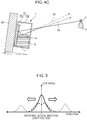
- Figs. 4A through 4C are cross-sectional views each illustrating the measurement system of Fig. 1 .
- Fig. 4A illustrates a state where the state of the object to be measured 100 has not changed.
- Fig. 4B illustrates a state where the object to be measured 100 is tilted with respect to a horizontal plane by an angle - ⁇ .
- Fig. 4C illustrates a state where the object to be measured 100 is tilted with respect to the horizontal plane by an angle + ⁇ .
- a clockwise angle with respect to a reference direction or a reference plane is expressed by using "+”
- a counterclockwise angle with respect to the reference direction or the reference plane is expressed by using "-”.
- the reference mirror 13a in the state where the state of the object to be measured 100 has not changed, the reference mirror 13a extends in the vertical direction and the bias mirror 13b is tilted with respect to the vertical direction by an angle + ⁇ .
- light or an electromagnetic wave emitted from the lighting device 2 to the reference mirror 13a is reflected by the two mirror surfaces of the reference mirror 13a and the movable mirror 14 and travels in a retroreflection direction A1 as indicated by the solid-line arrow.
- light or an electromagnetic wave emitted from the lighting device 2 to the bias mirror 13b is reflected by the two mirror surfaces of the bias mirror 13b and the movable mirror 14 and travels in a reflection direction B1 as indicated by the dash-line arrow.
- the reflection direction B1 is deviated from the retroreflection direction A1 by an angle -2 ⁇ .
- the reference mirror 13a and the bias mirror 13b are tilted with respect to the horizontal plane by the angle - ⁇ together with the object to be measured 100.
- the movable mirror 14, which floats on the surface of the liquid 15, keeps a horizontal state. Accordingly, an angle of the reference mirror 13a with respect to the vertical direction is - ⁇ .
- light or an electromagnetic wave emitted from the lighting device 2 to the reference mirror 13a is reflected by the reference mirror 13a and the movable mirror 14 and travels in a reflection direction A2.
- the reflection direction A2 is deviated from the retroreflection direction A1 by an angle +2 ⁇ .
- the reference mirror 13a and the bias mirror 13b are tilted with respect to the horizontal plane by the angle + ⁇ together with the object to be measured 100.
- the movable mirror 14, which floats on the surface of the liquid 15, keeps a horizontal state. Accordingly, an angle of the reference mirror 13a with respect to the vertical direction is + ⁇ .
- light or an electromagnetic wave emitted from the lighting device 2 to the reference mirror 13a is reflected by the reference mirror 13a and the movable mirror 14 and travels in a reflection direction A3.
- the reflection direction A3 is deviated from the retroreflection direction A1 by an angle -2 ⁇ .
- a single light beam or a single electromagnetic wave is emitted from the lighting device 2.
- the whole optical member 12 is irradiated with light or an electromagnetic wave emitted from the lighting device 2. Therefore, for example, besides light or an electromagnetic wave reflected by the fixed mirror 13 and the movable mirror 14 in this order and travelling in the reflection direction A2, there is light or an electromagnetic wave reflected by the movable mirror 14 and the fixed mirror 13 in this order and travelling in a reflection direction A2a, as illustrated in Fig. 4B .
- the reflection direction A2a is deviated from the retroreflection direction A1 by an angle -2 ⁇ .
- the reflection direction A2a is deviated from the retroreflection direction A1 by the same angle as the reflection direction A3 illustrated in Fig. 4C . Therefore, both in a case where the object to be measured 100 is tilted with respect to the horizontal plane by the angle - ⁇ and in a case where the object to be measured 100 is tilted with respect to the horizontal plane by the angle + ⁇ , there is reflected light or a reflected electromagnetic wave that is reflected in the same reflection direction. It is therefore impossible to determine in which direction the object to be measured 100 is tilted by using the reference mirror 13a only.
- the bias mirror 13b is provided in order to determine in which direction the object to be measured 100 is tilted.
- an angle of the bias mirror 13b with respect to the vertical direction is - ⁇ + ⁇ .
- light or an electromagnetic wave emitted from the lighting device 2 to the bias mirror 13b is reflected by the bias mirror 13b and the movable mirror 14 and travels in a reflection direction B2.
- the reflection direction B2 is deviated from the retroreflection direction A1 by an angle -2 (- ⁇ + ⁇ ).
- the angle 2( ⁇ - ⁇ ) formed between the reflection direction B2 and the retroreflection direction A1 is smaller than the angle 2 ⁇ formed between the reflection direction A2 and the retroreflection direction A1, and the reflection direction B2 is closer to the retroreflection direction A1 than the reflection direction A2.
- an angle of the bias mirror 13b with respect to the vertical direction is + ⁇ + ⁇ .
- light or an electromagnetic wave emitted from the lighting device 2 to the bias mirror 13b is reflected by the bias mirror 13b and the movable mirror 14 and travels in a reflection direction B3.
- the reflection direction B3 is deviated from the retroreflection direction A1 by an angle -2(+ ⁇ + ⁇ ).
- an angle 2( ⁇ + ⁇ ) formed between the reflection direction B3 and the retroreflection direction A1 is larger than the angle 2 ⁇ formed between the reflection direction A3 and the retroreflection direction A1, and the reflection direction B3 is farther from the retroreflection direction A1 than the reflection direction A3.
- the object to be measured 100 is tilted with respect to the horizontal plane by the angle - ⁇ in a case where a reflection direction of light or an electromagnetic wave reflected by the bias mirror 13b is closer to the retroreflection direction A1 than a reflection direction of light or an electromagnetic wave reflected by the reference mirror 13a. Meanwhile, it can be determined that the object to be measured 100 is tilted with respect to the horizontal plane by the angle + ⁇ in a case where a reflection direction of light or an electromagnetic wave reflected by the bias mirror 13b is farther from the retroreflection direction A1 than a reflection direction of light or an electromagnetic wave reflected by the reference mirror 13a.
- Figs. 4A through 4C it is assumed that each of the travelling directions A1 through A3 and B1 through B3 of reflected light or a reflected electromagnetic wave is a single line. Actually, however, the fixed mirror 13 and the movable mirror 14 each have slight unevenness, a placement error, an angle variation, and the like. For this reason, the reflected light or the reflected electromagnetic wave has diffuseness as indicated by the line with alternate long and short dashes K1 of Fig. 1 .
- Fig. 5 is a graph conceptually illustrating diffuseness of light or an electromagnetic wave reflected by the visualizer 1. The horizontal axis represents a direction in which reflected light travels. The vertical axis represents luminance.
- Deviation of reflected light from a retroreflection direction corresponds to a distance between a light source and a position which the reflected light reaches.
- a luminance distribution having a peak in the retroreflection direction is obtained as indicated by the solid line.
- the peak is divided and a distance thereof from the center becomes longer as indicated by the solid line, the dashed line, and the line with alternate long and short dashes. Since such a change of a light distribution occurs in an analog manner, a change of a tilt angle can be grasped as a change of luminance by grasping the light distribution and a change thereof in advance.
- the object to be measured 100 is tilted with respect to the horizontal plane by an angle ⁇ , and an angle formed between the fixed mirror 13 and the movable mirror 14 changes accordingly, as illustrated in Figs. 4B and 4C . Accordingly, a light distribution (reflection direction) of reflected light or a reflected electromagnetic wave travelling in the vicinity of the retroreflection direction changes in accordance with the tilt angle of the object to be measured 100 with respect to the horizontal plane. That is, there is a correlation between the tilt angle of the object to be measured 100 and a change of a light distribution of the reflected light or the reflected electromagnetic wave in the vicinity of the retroreflection direction. It is therefore possible to visualize and measure the tilt angle of the object to be measured 100 and a dynamic change of the tilt angle on the basis of a change of the light distribution of the reflected light or the reflected electromagnetic wave.
- light beams or electromagnetic waves that are reflected by a plurality of optical members 12 can be received by a single imaging device 3 by emitting light or an electromagnetic wave from the single lighting device 2 to the plurality of optical members 12. That is, by attaching a plurality of visualizers 1 onto the object to be measured 100 and emitting light or an electromagnetic wave from the lighting device 2 to the visualizers 1, it is possible to concurrently measure changes of luminance of reflected light or changes of light distributions of reflected electromagnetic waves reflected by the visualizers 1 by using the imaging device 3. This makes it possible to visualize the tilt angle of the object to be measured 100 and a dynamic change of the tilt angle and to measure the state of the object to be measured 100 in detail in a shorter period.
- the visualizer 1 does not include a component that consumes electric power, it is unnecessary to change batteries, and it is therefore possible to reduce the number of times of maintenance. Furthermore, the visualizer 1 can be manufactured at low cost, and degradation such as corrosion can be lessened.
- the optical member 12 is hardly affected by disturbance factors such as wind and corrosion. It is therefore possible to lessen the number of times of erroneous measurement caused by such disturbance factors.
- the surface of the housing 11 may be subjected to antifouling surface treatment.
- a wave absorber such as a porous resin may be provided on an inner surface of the housing 11. This makes it possible to make a liquid surface less wavy, thereby keeping rocking of the movable mirror 14 smaller.
- the liquid 15 may be transparent and have low volatility.
- the liquid 15 may be a material free from contamination and proliferation of bacteria and may be subjected to encapsulating processing free from contamination and proliferation of bacteria so that the liquid 15 does not become clouded.
- the movable mirror 14 may be configured to have a very low natural vibration frequency. In this case, the movable mirror 14 is unlikely to follow vibration of a frequency higher than the natural vibration frequency. It is therefore possible to measure a temporal change of the tilt angle of the object to be measured 100, i.e., vibration by extracting a temporal change of luminance of reflected light from an image taken by the imaging device 3. Furthermore, a degree of soundness can be diagnosed in more detail by analyzing degradation of a structure by using both the tilt angle and vibration.
- the electromagnetic wave may be an electromagnetic wave having a longer wavelength than light.
- external diameters of mirror surfaces of the fixed mirror 13 and the movable mirror 14 may be larger than the wavelength of the electromagnetic wave.
- the reference mirror 13a and the bias mirror 13b may have, for example, different color filters on front surfaces thereof so as to be distinguishable from each other.
- the reference mirror 13a and the bias mirror 13b may have different shapes.
- a distance between the visualizer 1 and the lighting device 2 and a distance between the visualizer 1 and the imaging device 3 are short.
- these distances may be several tens of meters or more or may be several hundreds of meters or more.
- the lighting device 2 emits light or an electromagnetic wave to the fixed mirror 13 and the movable mirror 14 from an obliquely upward direction.
- the lighting device 2 may emit light or an electromagnetic wave to the fixed mirror 13 and the movable mirror 14 from an obliquely downward direction.
- light or an electromagnetic wave emitted from the lighting device 2 enters the liquid 15 and is then refracted at a boundary between the liquid 15 and air.
- vibration of the object to be measured 100 can be measured in a similar manner to above, for example, by correcting an angle by using Snell's law.
- the movable mirror 14 is made of a metal having high reflectivity such as aluminum or a high-reflectivity film including a dielectric multilayer film. However, the present disclosure is not limited to this.
- the movable mirror 14 may be made of a resin or a metal.
- a natural vibration frequency of an object floating on a liquid surface becomes higher as a ratio of specific gravity of the object to specific gravity of the liquid becomes smaller.
- an amplitude of the natural vibration becomes smaller as the ratio of the specific gravity of the object to the specific gravity of the liquid becomes closer to 1. In view of this, the specific gravity of the movable mirror 14 may be close to the specific gravity of the liquid 15.
- the specific gravity may be adjusted, for example, by adding a weight.
- the specific gravity may be adjusted, for example, by making the movable mirror 14 hollow and thereby making the movable mirror 14 buoyant.
- One of the three mirrors of the optical member 12 is the movable mirror 14, and the other two of the three mirrors of the optical member 12 are the fixed mirror 13.
- the present disclosure is not limited to this.
- two of the three mirrors of the optical member 12 may be the movable mirror 14, and one of the three mirrors of the optical member 12 may be the fixed mirror 13.
- the two movable mirrors 14 may be connected to two sides of the fixed mirror 13 by using an elastic member (e.g., a plate spring).
- a gap may be provided between the two movable mirrors 14 and the fixed mirror 13 so that the two movable mirrors 14 do not directly collide with each other.
- the two movable mirrors 14 may have a shock-absorbing material so that the two movable mirrors 14 do not directly collide with each other. According to this configuration, it is possible to achieve sensitivity to biaxial vibration.
- the optical member 12 includes a single bias mirror 13b.
- the optical member 12 may include two or more bias mirrors 13b.
- tilt angles of two or more bias mirrors 13b with respect to the reference mirror 13a may be different.
- a tilt angle of the object to be measured 100 with respect to the horizontal plane can be measured even in a case where the tilt angle becomes large.
- the bias mirror 13b is tilted to the front side with respect to the reference mirror 13a by a predetermined angle.
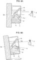
- the bias mirror 13b may be tilted by a predetermined angle ⁇ (e.g., 0.1 degrees to 1 degree) so that the linear ridge lines of the bias mirror 13b separated from the reference mirror 13a sideways by a larger amount as a distance to an upper side of the linear ridge lines becomes shorter, as illustrated in Figs. 6A and 6B .
- Fig. 6A illustrates a state where the state of the object to be measured 100 has not changed.
- Fig. 6B illustrates a state where the object to be measured 100 is tilted with respect to the horizontal plane by an angle - ⁇ .
- the imaging device 3 may include a plurality of cameras or a compound-eye camera. In this case, it is possible to identify a direction and an angle of reflected light or a reflected electromagnetic wave in more detail by comparing a plurality of pieces of image information obtained by the plurality of cameras or the compound-eye camera. That is, even in a case where a change of the state of the object to be measured 100 is very small, a minute change of a direction and an angle of reflected light or a reflected electromagnetic wave can be observed by the plurality of cameras or the compound-eye camera.
- the lighting device 2 may include a plurality of light sources 2A and 2B that emit light or an electromagnetic wave toward the visualizer 1, as illustrated in Fig. 7 .
- a diffusion component of reflected light or a reflected electromagnetic wave originating from light or an electromagnetic wave emitted from any of the light sources 2A and 2B can be received by the imaging device 3. It is therefore possible to image a change of luminance of reflected light by using the imaging device 3.
- a single light source may be moved to positions of the light sources 2A and 2B.
- the plurality of light sources may be aligned in the vertical direction or may be aligned in the horizontal direction.
- a reflection direction of light or an electromagnetic wave is deviated in the vertical direction.
- a reflection direction of light of an electromagnetic wave is deviated in the horizontal direction.
- a plurality of light sources may be provided both in the vertical direction and in the horizontal direction.
- the imaging device 3 Even in a case where the tilt angle of the object to be measured 100 in two directions (i.e., a front-back direction and a left-right direction) is large, a diffusion component of reflected light or a reflected electromagnetic wave originating from light or an electromagnetic wave emitted from any of the light sources 2 can be received by the imaging device 3. It is therefore possible to image a change of luminance of reflected light by using the imaging device 3.
- the plurality of light sources may be disposed at constant intervals or may be disposed at orderly intervals.
- Light beams or electromagnetic waves emitted by the plurality of light sources 2A and 2B may be different from each other in terms of at least one of a wavelength, a polarization state, and an irradiation timing so as to be distinguishable from each other.
- the polarization state includes, for example, linear polarization and circular polarization. This makes it possible to measure a tilt angle in two directions (e.g., the vertical direction and the horizontal direction).
- the plurality of light sources 2A and 2B may be disposed so that distances thereof from the imaging device 3 are different from each other.
- the plurality of light sources 2A and 2B may emit light or an electromagnetic wave in turn. In this case, it is possible to detect a deviation angle of a reflection direction with respect to the retroreflection direction and thereby measure a tilt angle of the object to be measured 100 on the basis of changes of light distributions of reflected light or reflected electromagnetic waves originating from the light sources 2A and 2B.
- light beams or electromagnetic waves emitted by the plurality of light sources 2A and 2B have different colors.
- the visualizer 1 appears to have a color that is mixture of a color of light emitted from the light source 2A and a color of light emitted from the light source 2B, it is possible to more accurately detect a deviation angle of a reflection direction with respect to the retroreflection direction on the basis of a ratio of the mixed colors.
- the movable mirror 14 has a rectangular plate shape and reflects light or an electromagnetic wave on a mirror surface parallel with a liquid surface.
- a movable mirror 61 having a triangular prism shape may be used so that light or an electromagnetic wave is reflected by a mirror surface 61 a that is tilted with respect to a liquid surface, as illustrated in Figs. 8A and 8B .
- Fig. 8A and 8B As illustrated in Fig.
- a light distribution of reflected light or a reflected electromagnetic wave in the vicinity of the retroreflection direction received by the imaging device 3 changes in accordance with a tilt state of the object to be measured 100.
- the tilt state of the object to be measured 100 can be measured on the basis of this change.
- the horizontal state of the movable mirror 14 is kept by floating the movable mirror 14 on the liquid surface of the liquid 15.
- the present disclosure is not limited to this.
- the support rod 74 is an example of a support member and is fixed to a housing 73.
- the movable mirror 71 is supported so as to be freely movable, and therefore the center of gravity of the movable mirror 71 is always located below, in the vertical direction, the inner corner part 72 that is a supporting point.
- the mirror surface 71a of the movable mirror 71 can keep a posture tilted with respect to the horizontal direction by a predetermined angle (e.g., 45 degrees).
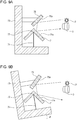
- the fixed mirror 75 is fixed to the housing 73 so that the mirror surface 71a of the movable mirror 71 and a mirror surface 75a of the fixed mirror 75 are orthogonal to each other, as illustrated in Fig. 9A . This makes it possible to reflect, in the retroreflection direction, light or an electromagnetic wave emitted from the lighting device 2. As illustrated in Fig.
- a travelling direction of reflected light or a reflected electromagnetic wave is deviated from the retroreflection direction by an angle +2 ⁇ . Since a light distribution of reflected light or a reflected electromagnetic wave in the vicinity of the retroreflection direction received by the imaging device 3 changes in accordance with a tilt state of the object to be measured 100, the tilt state of the object to be measured 100 can be measured on the basis of this change.
- a fixed mirror 81 may be fixed to a tilted surface of a housing 82. Furthermore, a movable mirror 83 may be supported, in the vicinity of an upper end of the fixed mirror 81, by the housing 82 with a spring 84 interposed therebetween.
- the spring 84 is an example of a support member and is, for example, a plate spring. As illustrated in Fig. 10A , in a case where the state of the housing 82 does not change, the spring 84 that is warped due to the gravity elastically supports the movable mirror 83.
- a mirror surface 83a of the movable mirror 83 on the lighting device 2 side can keep a posture orthogonal to a mirror surface 81a of the fixed mirror 81.
- light or an electromagnetic wave emitted from the lighting device 2 can be reflected in the retroreflection direction.
- a direction in which the spring 84 extends becomes closer to the vertical direction. This reduces load that is applied to deform the spring 84 by the gravity, thereby reducing warp of the spring 84.
- an angle formed between the mirror surface 81a of the fixed mirror 81 and the mirror surface 83a of the movable mirror 83 changes, and a reflection direction of light or an electromagnetic wave is deviated from the retroreflection direction by an angle +2 ⁇ . Since a light distribution of reflected light or a reflected electromagnetic wave in the vicinity of the retroreflection direction changes in accordance with a tilt state of the object to be measured 100, the tilt state of the object to be measured 100 can be measured on the basis of this change.
- the natural vibration frequency of the movable mirror 83 also changes in accordance with the tilt angle of the housing 82. That is, there is a correlation between the natural vibration frequency of the movable mirror 83 and the tilt angle of the housing 82.
- the object to be measured 100 is always vibrating slightly, for example, due to wind or noise. Accordingly, the movable mirror 83 also vibrates mainly at a natural vibration frequency that varies depending on the vibration of the object to be measured 100. It is also therefore possible to measure the tilt angle of the housing 82 by measuring the natural vibration frequency of the movable mirror 83.
- temperature need be corrected for accurate measurement since an elastic constant of a spring depends on the temperature.
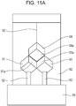
- each of two fixed mirrors 91 having a cubic shape may be fixed to a housing 93 with a fixing member 92 interposed therebetween. Furthermore, a movable mirror 94 having a cubic shape may be supported from above by a string 95.
- the string 95 is an example of a support member.
- the string 95 supports the movable mirror 94 so that a mirror surface 94a of the movable mirror 94 keeps a posture orthogonal to mirror surfaces 91a of the fixed mirrors 91. In this case, light or an electromagnetic wave emitted from the lighting device 2 can be reflected in the retroreflection direction.
- the fixed mirrors 91 are tilted by the angle - ⁇ together with the housing 93.
- the movable mirror 94 is supported by the string 95 so that the center of gravity thereof is directly below the string 95, the posture of the movable mirror 94 is kept.
- an angle formed between the mirror surfaces 91a of the fixed mirrors 91 and the mirror surface 94a of the movable mirror 94 changes, and a reflection direction of light or an electromagnetic wave is deviated from the retroreflection direction by an angle +2 ⁇ . Since a light distribution of reflected light or a reflected electromagnetic wave in the vicinity of the retroreflection direction changes in accordance with a tilt state of the object to be measured 100, the tilt state of the object to be measured 100 can be measured on the basis of this change.
- a fixed mirror moves together with the object to be measured.
- a movable mirror is supported by a support member so that a relative position thereof with the fixed mirror is changed by utilizing gravity.
- a relative positional relationship of the movable mirror with the fixed mirror can be changed in accordance with the tilt angle of the object to be measured.
- a visualizer can be manufactured at low cost, and degradation such as corrosion can be kept small.
- Fig. 12 is a flowchart of the measurement method.
- the following describes an example where the object to be measured 100 is a plurality of lighting poles beside a road bridge and a tilt angle of each of the plurality of lighting poles is measured from a running vehicle or the like, as illustrated in Fig. 13 .
- the lighting device 2 emits only light, and description about an electromagnetic wave is omitted.
- Fig. 13 illustrates an example in which the lighting device 2 includes a plurality of light sources that are aligned in a top-bottom direction and a left-right direction.
- Step S1 a plurality of visualizers 1 are attached to the objects to be measured 100.
- Step S2 light is emitted from the lighting device 2 to the objects to be measured 100, and an image including reflected light reflected in a retroreflection direction by the optical members 12 of the visualizers 1 is taken by the imaging device 3, as illustrated in Fig. 13 .
- Step S2 the plurality of light sources of the lighting device 2 emit light beams of different colors or emit light in turn toward the objects to be measured 100.
- colors of light beams reflected by the plurality of visualizers 1 change in accordance with tilt of the objects to be measured 100 or intensities of light beams reflected by the plurality of visualizers 1 change at a different timing in accordance with tilt of the objects to be measured 100.
- the measurement device 4 measures tilt angles of the objects to be measured 100 on the basis of the image taken by the imaging device 3.
- the measurement device 4 performs image processing such as sampling of a change of luminance of pixels corresponding to positions of the visualizers 1 from frame images that constitute the image taken by the imaging device 3. This makes it possible to extract changes of luminance of the plurality of visualizers 1 in the image and to measure tilt angles of the plurality of objects to be measured 100.
- the visualizer 1 attached to a lighting pole that is not tilted becomes bright when being irradiated with light by a light source closest to the imaging device 3 among the plurality of light sources of the lighting device 2.
- the visualizer 1 attached to a lighting pole that is tilted appears to have a color of light emitted from a different light source among the plurality of light sources of the lighting device 2.
- An absolute value of a tilt angle also depends on a distance between the object to be measured 100 and the imaging device. It is therefore possible to calculate an absolute value of a tilt angle by calculating the distance, for example, on the basis of the image.
- the plurality of visualizers 1 emit light beams of different colors or emit light at different timings in accordance with tilt angles of the objects to be measured 100. It is therefore possible to measure the tilt angles from the image taken by the imaging device 3. It is also possible to visually measure the tilt angles by selecting appropriate setting. Since reflected light retroreflected by the visualizer 1 has high directivity, the reflected light can be observed, for example, even from a position that is away by several hundreds of meters from the object to be measured 100.
- the measurement method is a measurement method that is more resistant to noise and a change of an environment than the conventional method.
- the measurement device 4 may include a storage unit in which data concerning a measured change of the state of the object to be measured 100 is accumulated and stored and a notification unit that gives a notification about an abnormality, for example, by a text or sound.
- the storage unit is, for example, a semiconductor memory.
- the notification unit is, for example, a monitor and/or a speaker. According to this configuration, it is possible to detect an abnormal portion and a degree of abnormality of the object to be measured 100 by comparing past data accumulated in the storage unit and data measured this time. Furthermore, when the notification unit notifies an administrator about the abnormality on the basis of a result of detection, maintenance of the object to be measured 100 can be conducted early.
- the lighting device 2 and the imaging device 3 may be fixed at positions remote from the object to be measured 100 or may be installed on a movable body such as an automobile or a helicopter. In a case where the lighting device 2 and the imaging device 3 are fixed at positions remote from the object to be measured 100, the imaging device 3 may be placed, for example, beside the lighting device 2 illuminating a bridge for a safety purpose or for a dramatic effect. This allows fixed-point observation.
- the image taken by the imaging device 3 includes the objects to be measured 100 dimly illuminated by the lighting device 2, the visualizers 1 that brightly shine due to retroreflection, and background such as street lamps and light from buildings. It is necessary to extract positions of the plurality of visualizers 1 from this image. In this case, for example, the positions of the visualizers 1 can be identified by causing the lighting device 2 to blink at the start of measurement or during measurement and specifying parts that blink in synchronization with the light of the lighting device 2.
- an LED that emits light in a wavelength range in which a spectrum of solar light on the ground is weak due to absorption by water molecules, for example, in the vicinity of 1.35 ⁇ m or in the vicinity of 1.15 ⁇ m may be used.
- the influence of solar light can be lessened, and it is therefore possible to achieve measurement with a high SN ration even during daytime.
- Fig. 14 illustrates an outline configuration of a state measurement system according to a second example of the present disclosure.
- the measurement system according to the second example is different from the measurement system according to the first example in that the measurement system includes a visualizer 110 instead of the visualizer 1.
- the second example is similar to the first example except for this point.
- the visualizer 110 performs measurement by changing a light distribution of reflected light or a reflected electromagnetic wave in the vicinity of a retroreflection direction in accordance with a change of a state of an object to be measured 100 by utilizing deformation of a bimetal caused, for example, by temperature or humidity.
- the visualizer 110 includes a housing 111 and an optical member 112 having light or electromagnetic wave retroreflection characteristics, as illustrated in Fig. 14 .
- the optical member 112 includes a fixed mirror 113 that is fixed to the housing 111 and a movable mirror 114 that is supported so as to be movable relative to the fixed mirror 113 in accordance with a change of a state of an object to be measured 100.
- the fixed mirror 113 is an example of another part of the optical member 112.
- the movable mirror 114 is an example of one part of the optical member 112.
- the fixed mirror 113 and the movable mirror 114 have, in mirror surfaces 113a and 114a for reflecting light or an electromagnetic wave, a metal having high reflectivity such as aluminum, a high-reflectivity film including a dielectric multilayer film, or the like.
- the movable mirror 114 includes a bimetal that deforms depending on temperature, humidity, an amount of moisture, a far-infrared ray, or radiation.
- the bimetal included in the movable mirror 114 is formed by joining two kinds of materials that have different coefficients of expansion.
- the movable mirror 114 is attached to the housing 111 with a connecting member 115 interposed therebetween.
- the connecting member 115 is, for example, attached to a central part of a surface of the movable mirror 114 opposite to the mirror surface 114a so that the movable mirror 114 can be deformed in accordance with a change of a state of the object to be measured 100.
- the mirror surface 114a of the movable mirror 114 is flat as indicated by the solid line in Fig. 14 , and the mirror surface 114a of the movable mirror 114 and a mirror surface 113a of the fixed mirror 113 are orthogonal to each other.
- light or an electromagnetic wave emitted from the lighting device 2 is reflected in a retroreflection direction as indicated by the solid-line arrow A1.
- the mirror surface 114a of the movable mirror 114 is curved as indicated by the dashed line in Fig. 14 , and the mirror surface 114a of the movable mirror 114 and the mirror surface 113a of the fixed mirror 113 are not orthogonal to each other.
- light or an electromagnetic wave emitted from the lighting device 2 is reflected as indicated by the alternate-long-and-short-dash-line arrow B4 or the dashed-line arrow B4a. That is, the reflected light or the reflected electromagnetic wave widely diffuses.
- Fig. 15 is a graph conceptually illustrating diffuseness of light reflected by the visualizer 110.
- the horizontal axis represents a direction in which reflected light travels.
- the vertical axis represents luminance.
- Deviation of reflected light from the retroreflection direction corresponds to a distance between a light source and a position which the reflected light reaches.
- a luminance distribution having a peak in the retroreflection direction is obtained as indicated by the solid line.
- the optical member 112 includes a single fixed mirror 113.
- the optical member 112 may include two fixed mirrors 113 that are orthogonal to each other. In a case where the two fixed mirrors 113 and the movable mirror 114 are disposed so as to be orthogonal to one another, light or an electromagnetic wave can be reflected in the retroreflection direction as described with reference to Fig. 3 .
- the bimetal of the movable mirror 114 is formed by joining two kinds of materials that are different in terms of a coefficient of expansion caused by temperature or the like.
- the materials, shape, and the like of the bimetal may be appropriately selected and designed in accordance with a measured state and a measurement range of the object to be measured 100.
- the movable mirror 114 itself includes a bimetal.
- the present disclosure is not limited to this.
- the movable mirror 114 may be attached to the housing 111 with the connecting member 116 constituted by a spiral bimetal interposed therebetween, as illustrated in Fig. 16 .
- the spiral bimetal rotates about a spiral axis in accordance with a change of a state of the object to be measured 100, and thus an angle formed between the two fixed mirrors 113 and the movable mirror 114 can be changed.
- the connecting member 115 is constituted by a bimetal
- the shape of the bimetal can be set relatively freely. It is therefore easy to adjust sensitivity by changing a degree of deformation of the bimetal relative to a change of the state of the object to be measured 100.
- the bimetal is not limited to a metal and can be, for example, paper or plastic.
- a similar effect can be obtained even by employing a material and a structure that change in accordance with a change of the state of the object to be measured 100 instead of the bimetal.
- the frequency of a change of intensity of reflected light depends on a natural vibration frequency of the movable mirror 114.
- a plane mirror (not illustrated) that is not deformed even when the state of the object to be measured 100 changes may be provided close to the movable mirror 113. According to this configuration, it is possible to accurately measure a change of the state of the object to be measured 100 on the basis of a ratio of reflectivity of the plane mirror and reflectivity of the movable mirror 113 in a similar manner to the case where it is determined in which direction the object to be measured 100 is tilted by using the reference mirror 13a and the bias mirror 13b in the first example.
- Fig. 17 illustrates an outline configuration of a measurement system according to a third example of the present disclosure.
- the measurement system according to the third example is different from the measurement system according to the first example in that it includes a visualizer 120 instead of the visualizer 1.
- the third example is similar to the first example except for this point.
- An object to be measured 100 is soil.
- the visualizer 120 is configured to measure a change of a state of an amount of moisture in the soil.
- the visualizer 120 includes a housing 121 and an optical member 122 having light or electromagnetic wave retroreflection characteristics, as illustrated in Fig. 17 .
- a tensiometer 125 is attached to the housing 121.
- the tensiometer 125 is an example of a stress unit that generates stress in accordance with a state of the object to be measured 100.
- the tensiometer 125 includes a porous cup 126, a pipe 127, and a Bourdon tube 128 having a curved part that is curved in a C shape.
- the porous cup 126 is made, for example, of porous pottery.
- the porous cup 126 is attached to one end of the pipe 127.
- the Bourdon tube 128 is attached to the other end of the pipe 127.
- the Bourdon tube 128 has a curved part 128a that is curved in a C shape.
- the curved part 128a is disposed in the housing 121.
- the porous cup 126 and the pipe 127 are filled with deaerated water and are hermetically sealed.
- moisture is discharged from the porous cup 126 to the soil, and the pipe 127 are depressurized in accordance with an amount of discharged moisture.
- the curved part 128a of the Bourdon tube 128 is deformed so that a radius of curvature thereof changes due to this change of pressure.
- the optical member 122 includes a fixed mirror 123 that is fixed to the housing 121 and a movable mirror 124 that is supported so as to be movable relative to the fixed mirror 123 in accordance with a change of a state of the object to be measured 100.
- the fixed mirror 123 is an example of another part of the optical member 122.
- the movable mirror 124 is an example of one part of the optical member 122.
- the fixed mirror 123 and the movable mirror 124 have, in mirror surfaces 113a and 114a for reflecting light or an electromagnetic wave, a metal having high reflectivity such as aluminum, a high-reflectivity film including a dielectric multilayer film, or the like.
- the movable mirror 124 is attached to the curved part 128a of the Bourdon tube 128.
- the Bourdon tube 128 is an example of a support member that supports the movable mirror 124.
- a mirror surface 124a of the movable mirror 124 and a mirror surface 123a of the fixed mirror 123 are orthogonal to each other. In this case, light or an electromagnetic wave emitted from the lighting device 2 is reflected in a retroreflection direction.
- the curved part 128a of the Bourdon tube 128 is deformed.
- the movable mirror 124 attached to the curved part 128a moves, and an angle formed between the mirror surface 124a of the movable mirror 124 and the mirror surface 123a of the fixed mirror 123 changes. Accordingly, a travelling direction of reflected light or a reflected electromagnetic wave is deviated from a retroreflection direction. Since a light distribution of reflected light or a reflected electromagnetic wave in the vicinity of the retroreflection direction changes in accordance with the amount of moisture of the object to be measured 100, the amount of moisture of the object to be measured 100 can be measured on the basis of this change.
- the amount of moisture in soil can be measured by using the tensiometer 125, use of the visualizer 120 makes it possible to measure the amount of moisture from a remote place without the need for a power source. For this reason, the visualizer 120 according to the third example is extremely useful for measurement of the amount of moisture in soil, for example, in an inconvenient place that is prone to sediment disasters.
- the visualizer 120 is attached to the tensiometer 125 and measures an amount of moisture in soil.
- the present disclosure is not limited to this.
- the visualizer 120 may be attached to a pH meter 131 and measures pH in soil, as illustrated in Fig. 18 .
- the pH meter 131 is an example of a stress unit.
- the pH meter 131 includes two kinds of metal electrodes 132 and 133 having different ionization tendencies and an analog meter 134.
- the metal electrodes 132 and 133 can be any combination of metals that generate electromotive force in water.
- the metal electrode 132 is, for example, zinc.
- the metal electrode 133 is, for example, silver or silver chloride.
- the movable mirror 124 is attached to the analog meter 134.
- the analog meter 134 is an example of a support member that supports the movable mirror 124.
- the mirror surface 124a of the movable mirror 124 attached to the analog meter 134 and the mirror surface 123a of the fixed mirror 123 are orthogonal to each other. In this case, light or an electromagnetic wave emitted from the lighting device 2 is reflected in a retroreflection direction.
- the electric potential difference between the metal electrodes 132 and 133 changes from the reference value in accordance with pH of moisture in the soil.
- This electric potential difference serves as electromotive force that generates electromagnetic force or electrostatic force, and this electromagnetic force or electrostatic force moves the analog meter 134 and the movable mirror 124, thereby changing an angle formed between the mirror surface 124a of the movable mirror 124 and the mirror surface 123a of the fixed mirror 123.
- a travelling direction of reflected light or a reflected electromagnetic wave is deviated from the retroreflection direction.
- the amount of moisture of the object to be measured 100 can be measured on the basis of this change.
- the visualizer 120 Although pH of moisture in soil can be measured by using the pH meter 131, use of the visualizer 120 makes it possible to measure an amount of moisture from a remote place without the need for a power source. For this reason, the visualizer 120 according to the third example is extremely useful for measurement of pH of moisture in soil in a wide range, for example, for an agricultural purpose or for the purpose of prevention of disasters.
- the tensiometer 125 and the pH meter 131 have been described as examples of a stress unit that generates stress in accordance with the state of the object to be measured 100.
- the stress unit may be one (e.g., a barometer, a piezoelectric body, or a voice coil motor) that can generate stress upon occurrence of some sort of change of a state (e.g., atmospheric pressure, acceleration, or distortion) of the object to be measured 100 and move the movable mirror 124 by the stress.
- a state e.g., atmospheric pressure, acceleration, or distortion
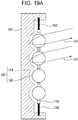
- Figs. 19A and 19B illustrate an outline configuration of a visualizer included in a measurement system according to an Embodiment of the present disclosure.
- the measurement system according to the Embodiment is different from the measurement system according to the first example in that it includes a visualizer 140 having a beaded structure instead of the visualizer 1.
- the Embodiment is similar to the first example except for this point.
- the visualizer 140 utilizes deformation of a bimetal that occurs depending on temperature, humidity, or the like.
- the visualizer 140 performs measurement by changing a light distribution of reflected light or a reflected electromagnetic wave in the vicinity of a retroreflection direction in accordance with a change of a state of the object to be measured 100.
- the visualizer 140 includes a housing 141 and an optical member 142 having light or electromagnetic wave retroreflection characteristics, as illustrated in Figs. 19A and 19B .
- the optical member 142 includes a spherical lens 143 and a concave reflection member 144 that is disposed behind the spherical lens 143 (on a side far from the lighting device 2).
- the spherical lens 143 is movable independently of the concave reflection member 144.
- the concave reflection member 144 has a concave surface that is concentric with the surface of the spherical lens 143. That is, the concave reflection member 144 has a concave surface that is part of a spherical surface.
- the concave reflection member 144 serves as a mirror surface that reflects light or an electromagnetic wave.
- a relative positional relationship between the spherical lens 143 and the concave reflection member 144 changes in accordance with a change of a state of the object to be measured 100.
- the spherical lens 143 is an example of one part of the optical member 142
- the concave reflection member 144 is an example of another part of the optical member 142.
- a relative positional relationship between the object to be measured 100 and the concave reflection member 144 may be fixed or a relative positional relationship between the object to be measured 100 and the spherical lens 143 may be fixed.
- the spherical lens 143 is embedded in a hole for position fixation that is provided in a plate member 145.
- the plate member 145 is attached to the housing 141 with a support member 146 interposed therebetween.
- the support member 146 includes a bimetal that deforms depending on temperature, humidity, an amount of moisture, a far-infrared ray, or radiation.
- the bimetal of the support member 146 is straight as illustrated in Fig. 19A .
- the concave reflection member 144 is located at a focal position of the spherical lens 143. Light or an electromagnetic wave reflected by the concave reflection member 144 travels in a retroreflection direction A1 through the spherical lens 143.
- the bimetal of the support member 146 is curved as illustrated in Fig. 19B .
- the spherical lens 143 moves forward, and the concave reflection member 144 is deviated from the focal position of the spherical lens 143.
- Light or an electromagnetic wave reflected by the concave reflection member 144 travels in a reflection direction B5 deviated from the retroreflection direction A1 through the spherical lens 143. Since a light distribution of reflected light or a reflected electromagnetic wave in the vicinity of the retroreflection direction changes in accordance with a change of a state of the object to be measured 100, the state of the object to be measured 100 can be measured on the basis of this change.
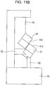
- the support member 146 may be a string or a spring that supports the spherical lens 143 from above so that the spherical lens 143 keeps posture thereof irrespective of whether or not the housing 141 is tilted with respect to the horizontal plane as in the configuration described with reference to Figs. 11A through 11C . According to this configuration, a tilt angle of the object to be measured 100 can be measured.
- a visualizer according to an additional Example has a similar configuration to the visualizer 1 according to the first example.
- an acrylic container was used as the housing 11.
- Water was used as the liquid 15.
- a plastic mirror obtained by vapor-depositing aluminum on a polyethylene plate having a thickness of 0.5 mm was used as the movable mirror 14.
- Specific gravity of the movable mirror 14 was adjusted by attaching a piece of aluminum onto a rear side thereof. When the specific gravity of the movable mirror 14 was adjusted so that more than a half of the movable mirror 14 sinks in the liquid 15, rocking of the movable mirror 14 was very small even when the housing 11 shakes.
- the reference mirror 13a and the bias mirror 13b a mirror obtained by vapor-depositing an aluminum film having a thickness of 0.2 ⁇ m onto an acrylic linear prism sheet having an apex angle of 90 degrees, a prism pitch of 1 mm, and a thickness of 2 mm was used.
- the reference mirror 13a was attached to the housing 11 so that ridge lines of prisms were parallel with a side surface of the housing 11.
- the bias mirror 13b was attached to the housing 11 so that ridge lines of prisms were tilted by 1 degree and were spaced away forward by a larger amount as a distance to an upper side became shorter. A spacer was provided between an upper part of the bias mirror 13b and the housing 11.
- the visualizer according to the additional Example configured as above was placed on a tilt table whose tile can be fine-adjusted by a micrometer.
- the visualizer was irradiated with laser light from a position that is away by 10 m from the visualizer, reflected light reflected by the visualizer was projected on graph paper on a wall, and thus a travelling direction of the reflected light was measured.
- the reflected light correctly returned to the position of a laser light source, i.e., exhibited perfect retroreflection characteristics.
- the travelling direction of the reflected light was deviated upward or downward by a deviation angle that is two times as large as the tilt angle.
- the travelling direction of the reflected light was deviated leftward or rightward by a deviation angle that is two times as large as the tilt angle.
- a compound-eye digital camera that was capable of taking a 3D image was used as the imaging device 3.
- a lighting device that includes LED lamps of three (RGB) colors aligned in three columns and three rows at 3 mm intervals was used as the lighting device 2.
- the lighting device 2 and the imaging device 3 were placed at a point that is obliquely upward by approximately 15 degrees and is away by 100 m from the visualizer. In this state, light was emitted from the lighting device 2 toward the visualizer, and reflected light was imaged by the imaging device 3.
- the intervals of 3 mm of the LED lamps correspond to 0.0017 degrees (approximately 6.2 seconds) at the point that is away by 100 m.
- the visualizer was found as a small bright point in the image taken by the imaging device 3, and the luminance thereof fluctuated due to constant vibration. Therefore, an average during 5 seconds was calculated as a still state.
- the image was taken by the imaging device 3 while gradually changing the tilt angle of the tilt table. As a result, it was confirmed that the imaging device 3 imaged different LED light every time the tilt angle was changed by 0.00086 degrees that was 1/2 of 0.0017 degrees. It was thus confirmed that a tilt angle of an object to be measured can be measured.
- a difference in luminance was also seen in an image taken by the compound-eye digital camera, and it was also confirmed that a tilt angle of an object to be measured can be measured in more detail by reducing a lens interval of compound-eye lenses. Furthermore, in a case where the tilt angle of the visualizer was vibrated so as to draw a sine waveform by using a vibrator, brightness of the visualizer in a taken image changed in accordance with the frequency of the vibration. It was thus confirmed that vibration of an object to be measured can also be measured.
- the present disclosure makes it possible to visualize a state of an object to be measured without the need for a power source and is therefore useful, for example, for evaluation and monitoring of a degree of soundness of not only a public structure such as a bridge or a tunnel, but also a machine or a building and management of a farm land. Furthermore, it is also possible to measure a state of a whole object to be measured from a plane or a satellite by using a large-sized visualizer. Therefore, the present disclosure is also applicable to monitoring of dangerous places, for example, sediment disasters.
Landscapes
- Physics & Mathematics (AREA)
- General Physics & Mathematics (AREA)
- Engineering & Computer Science (AREA)
- Remote Sensing (AREA)
- Radar, Positioning & Navigation (AREA)
- Optics & Photonics (AREA)
- Health & Medical Sciences (AREA)
- Chemical & Material Sciences (AREA)
- Life Sciences & Earth Sciences (AREA)
- Multimedia (AREA)
- Signal Processing (AREA)
- Pathology (AREA)
- Analytical Chemistry (AREA)
- Biochemistry (AREA)
- General Health & Medical Sciences (AREA)
- Immunology (AREA)
- Electrochemistry (AREA)
- Chemical Kinetics & Catalysis (AREA)
- Molecular Biology (AREA)
- Computer Vision & Pattern Recognition (AREA)
- Theoretical Computer Science (AREA)
- Investigating Or Analysing Materials By Optical Means (AREA)
- Electromagnetism (AREA)
- Computer Networks & Wireless Communication (AREA)
- Length Measuring Devices By Optical Means (AREA)
Description
- The present disclosure relates to a visualizer that is attached to an object to be measured, and a measurement system and a measurement method using the visualizer.
- In recent years, the concept of Internet of Things (loT) that enables various objects to be connected to the Internet by using a sensor and the like attached to these objects and analysis and use of big data that is a collection of a wide variety and a large volume of data have been attracting attention. Especially in the fields such as infrastructure, civil engineering, and plant, techniques for monitoring a tilt angle, vibration, temperature, humidity, an amount of moisture, and the like of an object to be measured such as a bridge, a tunnel, a machine, or ground over a sensor network have been vigorously developed.
- In Japan, a lot of public structures such as bridges and tunnels were constructed during the high-growth period of the Japanese economy (in the 1970's), and it is expected that the number of structures that outlive their usefulness rapidly increase in the future. In view of the circumstance, in recent years, research and development of techniques for automatically inspecting an infrastructure by using a sensor in order to keep an increase in cost of maintenance of the infrastructure small and prevent accidents have been conducted.
- For example, the University of Illinois has developed a system for analyzing vibration and the like on the basis of data transmitted from a large number of wireless sensor nodes that include sensors such as an acceleration sensor and a temperature sensor, a CPU, and a wireless unit and that are attached to an object to be measured (Illinois Structural Health Monitoring Project).
- Furthermore, research and development of techniques for measuring a tilt angle, natural vibration, an amount of moisture, and the like of ground by using a wireless sensor have been conducted in order to prevent disasters such as a sediment disaster caused by abnormal weather such as localized torrential rain that is seen more frequently than before in recent years.
-
US 2012/033710 A1 an optical temperature sensor.GB 2 159 940 ACN 1 384 343 A -
JP S55 178194 U DE 33 07 966 A1 relates to a temperature sensor. - Non-Patent Literature 1 describes a sensor network that monitors a state of a railway by using a clinometer, a displacement meter, and the like.
- NPL 1: RRR, Vol. 70, No. 11, November 2013, pp. 22-25, "Jyotai Kanshi No Tameno Sensor Network Wo Kouchiku Suru (Construction of Sensor Network for State Monitoring)"
- An aspect of the present disclosure provides a visualizer that makes it possible to visualize a state of an object to be measured.
- A visualizer according to the present invention is defined in
Claim 1. Further advantageous embodiments are defined in the dependent claims. - A visualizer according to an aspect of the present disclosure makes it possible to visualize a state of an object to be measured.
-
- [
Fig. 1] Fig. 1 illustrates an outline configuration of a measurement system according to a first example of the present disclosure not part of the invention but facilitates its understanding - [
Fig. 2] Fig. 2 is a cross-sectional view illustrating a principle of reflection of light or an electromagnetic wave by an optical member. - [
Fig. 3] Fig. 3 is a perspective view illustrating a principle of reflection of light or an electromagnetic wave by the optical member. - [
Fig. 4A] Fig. 4A is a cross-sectional view of the measurement system ofFig. 1 and illustrates a state where a state of an object to be measured has not changed. - [
Fig. 4B] Fig. 4B is a cross-sectional view of the measurement system ofFig. 1 and illustrates a state where the object to be measured is tilted with respect to a horizontal plane by an angle -θ. - [
Fig. 4C] Fig. 4C is a cross-sectional view of the measurement system ofFig. 1 and illustrates a state where the object to be measured is tilted with respect to the horizontal plane by an angle +θ. - [
Fig. 5] Fig. 5 is a graph conceptually illustrating diffuseness of reflected light reflected by a visualizer included in the measurement system ofFig. 1 . - [
Fig. 6A] Fig. 6A is a side view illustrating a state where a bias mirror is tilted sideways so as to be spaced away from a reference mirror in a larger amount as a distance to an upper side becomes shorter in the visualizer included in the measurement system ofFig. 1 and illustrates a state where the state of the object to be measured has not changed. - [
Fig. 6B] Fig. 6B is a side view illustrating a state where the visualizer ofFig. 6A is tilted with respect to the horizontal plane by an angle -θ. - [
Fig. 7] Fig. 7 is a plan view illustrating how light emitted from a plurality of light sources of the lighting device is reflected by the visualizer ofFig. 6B . - [
Fig. 8A] Fig. 8A is a cross-sectional view illustrating a modification of the visualizer included in the measurement system ofFig. 1 . - [
Fig. 8B] Fig. 8B is a cross-sectional view illustrating a state where the visualizer ofFig. 8A is tilted with respect to the horizontal plane by an angle -θ. - [
Fig. 9A] Fig. 9A is a cross-sectional view illustrating a modification of the visualizer included in the measurement system ofFig. 1 . - [
Fig. 9B] Fig. 9B is a cross-sectional view illustrating a state where the visualizer ofFig. 9A is tilted with respect to the horizontal plane by an angle -θ. - [
Fig. 10A] Fig. 10A is a cross-sectional view illustrating a modification of the visualizer included in the measurement system ofFig. 1 . - [
Fig. 10B] Fig. 10B is a cross-sectional view illustrating a state where the visualizer ofFig. 10A is tilted with respect to the horizontal plane by an angle -θ. - [
Fig. 11A] Fig. 11A is a front view illustrating a modification of the visualizer included in the measurement system ofFig. 1 . - [
Fig. 11B] Fig. 11B is a side view illustrating the modification of the visualizer included in the measurement system ofFig. 1 . - [
Fig. 11C] Fig. 11C is a side view illustrating a state where the visualizer ofFig. 11B is tilted with respect to the horizontal plane by an angle -θ. - [
Fig. 12] Fig. 12 is a flowchart of a measurement method using the measurement system ofFig. 1 . - [
Fig. 13] Fig. 13 is a perspective view illustrating how a plurality of lighting poles beside a road bridge are measured by using the measurement system ofFig. 1 . - [
Fig. 14] Fig. 14 illustrates an outline configuration of a measurement system according to a second example not part of the invention but facilitates its understanding of the present disclosure. - [
Fig. 15] Fig. 15 is a graph conceptually illustrating diffuseness of reflected light reflected by a visualizer included in the measurement system ofFig. 14 . - [
Fig. 16] Fig. 16 is a perspective view illustrating a modification of the visualizer included in the measurement system ofFig. 14 . - [
Fig. 17] Fig. 17 illustrates an outline configuration of a measurement system according to Third Embodiment of the present disclosure. - [
Fig. 18] Fig. 18 is a cross-sectional view illustrating a modification of the state measurement system according to a third example of the present disclosure. - [
Fig. 19A] Fig. 19A is a cross-sectional view of a visualizer included in a measurement system according to an embodiment of the present disclosure and illustrates the visualizer in a case where a state of an object to be measured has not changed. - [
Fig. 19B] Fig. 19B is a cross-sectional view of the visualizer included in the measurement system according to the embodiment of the present disclosure and illustrates the visualizer in a case where the state of the object to be measured has changed. - The present disclosure relates to a visualizer that makes it possible to visualize a tilt angle, vibration, temperature, humidity, an amount of moisture, and the like of an object to be measured such as a bridge, a tunnel, a machine, or ground and to a measurement system and a measurement method using the visualizer.
- According to a measurement method using wireless sensor nodes, it is possible to concurrently measure an entire object to be measured by attaching a plurality of wireless sensor nodes all around the object to be measured. However, according to this measurement method, electric power consumption of electric components such as a sensor, a CPU, and a wireless unit that are provided in each of the wireless sensor nodes is large, and it is therefore necessary to frequently change batteries.
- Since monitoring of a state of an infrastructure, a natural environment, or the like is often done under a harsh environment such as a dangerous place (e.g., a high place) or an inconvenient place, it is not easy to change batteries and it is therefore required to keep the number of times of maintenance as small as possible.
- Meanwhile, in a case where each of the wireless sensor nodes is made up of electric components that consume small electric power, it is possible to lessen the frequency of battery change. In this case, however, it is necessary to install a lot of relay units, and cost for installation of the relay units is high. Furthermore, it is necessary to change batteries of the relay units. Furthermore, electric components are easy to corrode and therefore have a short lifetime.
- As an example of a measurement method that does not use a sensor, a measurement method using a laser Doppler velocimeter. The laser Doppler velocimeter uses a Doppler effect. Specifically, laser is emitted from the meter toward an object to be measured, and speed of the object to be measured relative to the meter is measured on the basis of a change of a wavelength of a wave reflected by the object to be measured. Use of this laser Doppler velocimeter makes it possible to visualize and measure, for example, vibration added to the object to be measured. However, according to the measurement method using a laser Doppler velocimeter, only a single position can be measured at one time, and it takes a considerable time to measure a state of the whole of the object to be measured.
- Besides the measurement method using a laser Doppler velocimeter, there are other measurement methods using laser. However, each of these measurement methods is a method for measuring slight displacement of an object to be measured by using coherence or directivity of laser light. It is therefore difficult to perform accurate measurement under disturbance such as wind or rain. Furthermore, an expensive device is needed.
- In view of the circumstances, the inventor of the present invention found as a result of diligent studies that these problems can be improved by using an optical member having light or electromagnetic wave retroreflection characteristics and configuring the optical member so that part of the optical member is displaced in accordance with a change of a state of an object to be measured.
- Embodiments of the present disclosure are described below with reference to the drawings. The present disclosure is not limited by these embodiments. Identical or similar constituent elements are given identical reference signs, and description thereof is sometimes omitted.
-
Fig. 1 is illustrates an outline configuration of a state measurement system according to the first example of the present disclosure. The measurement system includes avisualizer 1, alighting device 2, animaging device 3, and ameasurement device 4. - The
visualizer 1 is attached to an object to be measured 100 such as a bridge or a tunnel. Thevisualizer 1 visualizes a tilt angle and a dynamic change of the tilt angle of the object to be measured 100 with respect to a vertical direction (also called a gravity direction). For simplification of description, it is assumed that the object to be measured 100 is a rectangular parallelepiped and one side thereof is parallel with the vertical direction. - The
lighting device 2 is a device that emits light or an electromagnetic wave toward thevisualizer 1. Thelighting device 2 may be a light source that does not generate much flicker, for example, a device such as a DC (direct current)-driven LED. Thelighting device 2 need not be a special lighting device, as long as thelighting device 2 has an irradiation angle appropriate for irradiation of the object to be measured 100 and brightness that depends on an object distance and an environment. Examples of thelighting device 2 include an LED light, an HID light, a halogen light, and a mercury light. For example, thelighting device 2 includes a light source such as a white LED and an emission optical system and emits light from an emission opening of the emission optical system. - The
imaging device 3 is a device that takes an image including a reflected light or a reflected electromagnetic wave that is reflected in a retroreflection direction by theoptical member 12, as illustrated in Fig. Theimaging device 3 is disposed close to thelighting device 2. Theimaging device 3 can be, for example, a camera or a radar. Theimaging device 3 may be, for example, a digital video camera that includes a CMOS or a CCD and an incident-side lens. In this case, a distance between a center of the incident-side lens of theimaging device 3 and a center of the emission opening of thelighting device 2 may be 1 m or less or may be 50 cm or less. Theimaging device 3 and thelighting device 2 may be fixedly coupled to each other so that a positional relationship between theimaging device 3 and thelighting device 2 does not change during shooting. This allows stable shooting and measurement by retroreflection characteristics of thevisualizer 1 that will be described later even in a case where theimaging device 3 is mounted on a movable body or shakes due to disturbance such as wind. - The
measurement device 4 is a device that measures a state of the object to be measured 100 on the basis of an image taken by theimaging device 3. Themeasurement device 4 measures a tilt angle of the object to be measured 100 on the basis of an image taken by theimaging device 3. Themeasurement device 4 also has a function of controlling thelighting device 2. Themeasurement device 4 can be realized, for example, by a personal computer and software installed in the personal computer. Themeasurement device 4 may include, for example, a memory in which software and image data are stored, a processor, and a display. - Next, the configuration of the
visualizer 1 is described in more detail. Thevisualizer 1 includes atransparent housing 11 and theoptical member 12 that has light or electromagnetic wave retroreflection characteristics, as illustrated inFig. 1 . - The term "retroreflection" refers to characteristics of light reflected back to a source of incident light. The retroreflection characteristics are widely used, for example, for a reflective material of a traffic sign.
Fig. 2 is a conceptual diagram illustrating the principle of retroreflection. When light or an electromagnetic wave entersmirrors line arrow 51 or the dotted-line arrow 52. A total of a sum of reflection angles of the two reflections and an angle (90 degrees) formed between themirror 50a and themirror 50b is 180 degrees. Accordingly, reflected light or a reflected electromagnetic wave that is reflected by themirror 50a and themirror 50b travels in an opposite direction to the incident direction. Hereinafter, the travelling direction of the light or the electromagnetic wave travelling in the opposite direction to the incident direction is referred to as a "retroreflection direction". In a case where threemirrors 50a through 50c are disposed so as to be orthogonal to one another as illustrated inFig. 3 , light or an electromagnetic wave that enters the threemirrors 50a through 50c is reflected three times and is reflected in a retroreflection direction. - In a case where the configuration of these three
mirrors 50a through 50c (e.g., an angle at which themirrors 50a through 50c intersect, irregularity of surfaces of themirrors 50a through 50c) changes and does not satisfy a condition for retroreflection, the direction in which the reflected light or the reflected electromagnetic wave travels is deviated from the retroreflection direction. The state measurement system is configured to visualize and measure a state of an object to be measured by utilizing this property. - Also in a conventional measurement method such as a measurement method using laser, a member having retroreflection characteristics is attached to an object to be measured. However, in the conventional measurement method, the shape and reflection characteristic of the retroreflection member are not changed. In the conventional measurement method, a member having retroreflection characteristics is used just to make an object to be measured noticeable by increasing the intensity of radiation of reflected light.
- Meanwhile, a state of the
visualizer 1 changes in accordance with a change of a state of the object to be measured 100, and the retroreflection characteristics change accordingly. According to this configuration, as the distance between theimaging device 3 and thevisualizer 1 becomes larger, a position which the reflected light or the reflected electromagnetic wave reaches is deviated from the retroreflection direction in a larger degree just because an angle at which the three mirrors intersect is deviated from a right angle even by a slight degree. That is, according to thevisualizer 1, it is possible to amplify a change of a state of an object to be measured. Since thevisualizer 1 can function as a highly sensitive sensor, it is possible to easily measure a change of a state of an object to be measured. - Furthermore, sophisticated measurement such as measurement using a Doppler effect or measurement of a flight period by picoseconds is not needed to detect a change of a state of an object to be measured, unlike the conventional measurement methods.
- The
optical member 12 includes a fixedmirror 13 fixed to thehousing 11 and amovable mirror 14 floating on a surface of atransparent liquid 15 as illustrated inFig. 1 . The fixedmirror 13 is an example of another part of theoptical member 12 and is an example of a fixed part having a fixed relative positional relationship with the object to be measured 100. Themovable mirror 14 is an example of one part of theoptical member 12 and is an example of a movable part supported so as to be movable with respect to the fixed part. The liquid 15 is an example of a support member. Themovable mirror 14 is supported so that a relative positional relationship thereof with the fixedmirror 13 changes in accordance with a change of a state of the object to be measured 100. The fixedmirror 13 and themovable mirror 14 each have, in a part serving as a mirror surface reflecting light or an electromagnetic wave, a metal having high reflectivity such as aluminum, a high-reflectivity film including a dielectric multilayer film, or the like. Thehousing 11 is made, for example, of a resin, a metal, or a combination thereof. - The fixed
mirror 13 includes areference mirror 13a and abias mirror 13b that is disposed so as to be tilted forward with respect to thereference mirror 13a by a predetermined angle (e.g., 0.1 degrees to 1 degree). Thereference mirror 13a and thebias mirror 13b each has a linear prism shape. That is, thereference mirror 13a and thebias mirror 13b each has a plurality of rectangular mirror surfaces that are disposed in a zig-zag manner so that long sides thereof are connected to one another and are orthogonal to one another. - The
reference mirror 13a is fixed to thehousing 11 so that linear ridge lines thereof extend in the vertical direction. Thebias mirror 13b is disposed adjacent to thereference mirror 13a and is fixed to thehousing 11. Thebias mirror 13b is tilted with respect to thereference mirror 13a by a predetermined angle δ (e.g., 0.1 degrees to 1 degree) so that the linear ridge lines of thebias mirror 13b separates farther from thehousing 11 to the front side (thelighting device 2 side) as a distance to an upper side of the linear ridge lines becomes shorter (seeFig. 4A ). Thereference mirror 13a and thebias mirror 13b, for example, may have different color filters on front surfaces thereof or may have different shapes so as to be distinguishable from each other. - In a case where the ridge lines of the
reference mirror 13a extend in the vertical direction, themovable mirror 14 is disposed so as to be orthogonal to two rectangular mirror surfaces that are adjacent to each other and orthogonal to each other. That is, the two mirror surfaces of thereference mirror 13a and themovable mirror 14 each correspond to any one of the threemirrors 50a through 50c described with reference toFig. 3 . Accordingly, a light beam A1 emitted from thelighting device 2 is reflected by the two mirror surfaces of thereference mirror 13a and themovable mirror 14 and travels in the retroreflection direction as indicated by the solid-line arrow ofFig. 1 . -
Figs. 4A through 4C are cross-sectional views each illustrating the measurement system ofFig. 1 .Fig. 4A illustrates a state where the state of the object to be measured 100 has not changed.Fig. 4B illustrates a state where the object to be measured 100 is tilted with respect to a horizontal plane by an angle - θ.Fig. 4C illustrates a state where the object to be measured 100 is tilted with respect to the horizontal plane by an angle +θ. In the drawings, a clockwise angle with respect to a reference direction or a reference plane is expressed by using "+", and a counterclockwise angle with respect to the reference direction or the reference plane is expressed by using "-". - As illustrated in
Fig. 4A , in the state where the state of the object to be measured 100 has not changed, thereference mirror 13a extends in the vertical direction and thebias mirror 13b is tilted with respect to the vertical direction by an angle +δ. In this state, light or an electromagnetic wave emitted from thelighting device 2 to thereference mirror 13a is reflected by the two mirror surfaces of thereference mirror 13a and themovable mirror 14 and travels in a retroreflection direction A1 as indicated by the solid-line arrow. Meanwhile, light or an electromagnetic wave emitted from thelighting device 2 to thebias mirror 13b is reflected by the two mirror surfaces of thebias mirror 13b and themovable mirror 14 and travels in a reflection direction B1 as indicated by the dash-line arrow. The reflection direction B1 is deviated from the retroreflection direction A1 by an angle -2δ. - As illustrated in
Fig. 4B , in the state where the object to be measured 100 is tilted with respect to the horizontal plane by the angle -θ, thereference mirror 13a and thebias mirror 13b are tilted with respect to the horizontal plane by the angle - θ together with the object to be measured 100. Meanwhile, themovable mirror 14, which floats on the surface of the liquid 15, keeps a horizontal state. Accordingly, an angle of thereference mirror 13a with respect to the vertical direction is -θ. In this state, light or an electromagnetic wave emitted from thelighting device 2 to thereference mirror 13a is reflected by thereference mirror 13a and themovable mirror 14 and travels in a reflection direction A2. The reflection direction A2 is deviated from the retroreflection direction A1 by an angle +2θ. - As illustrated in
Fig. 4C , in the state where the object to be measured 100 is tilted with respect to the horizontal plane by the angle +θ, thereference mirror 13a and thebias mirror 13b are tilted with respect to the horizontal plane by the angle +θ together with the object to be measured 100. Meanwhile, themovable mirror 14, which floats on the surface of the liquid 15, keeps a horizontal state. Accordingly, an angle of thereference mirror 13a with respect to the vertical direction is +θ. In this state, light or an electromagnetic wave emitted from thelighting device 2 to thereference mirror 13a is reflected by thereference mirror 13a and themovable mirror 14 and travels in a reflection direction A3. The reflection direction A3 is deviated from the retroreflection direction A1 by an angle -2θ. - For simplification of description, in
Figs. 4A through 4C , it is assumed that a single light beam or a single electromagnetic wave is emitted from thelighting device 2. However, actually, the wholeoptical member 12 is irradiated with light or an electromagnetic wave emitted from thelighting device 2. Therefore, for example, besides light or an electromagnetic wave reflected by the fixedmirror 13 and themovable mirror 14 in this order and travelling in the reflection direction A2, there is light or an electromagnetic wave reflected by themovable mirror 14 and the fixedmirror 13 in this order and travelling in a reflection direction A2a, as illustrated inFig. 4B . The reflection direction A2a is deviated from the retroreflection direction A1 by an angle -2θ. That is, the reflection direction A2a is deviated from the retroreflection direction A1 by the same angle as the reflection direction A3 illustrated inFig. 4C . Therefore, both in a case where the object to be measured 100 is tilted with respect to the horizontal plane by the angle -θ and in a case where the object to be measured 100 is tilted with respect to the horizontal plane by the angle +θ, there is reflected light or a reflected electromagnetic wave that is reflected in the same reflection direction. It is therefore impossible to determine in which direction the object to be measured 100 is tilted by using thereference mirror 13a only. Thebias mirror 13b is provided in order to determine in which direction the object to be measured 100 is tilted. - Specifically, as illustrated in
Fig. 4B , in the state where the object to be measured 100 is tilted with respect to the horizontal plane by the angle -θ, an angle of thebias mirror 13b with respect to the vertical direction is -θ + δ. In this state, light or an electromagnetic wave emitted from thelighting device 2 to thebias mirror 13b is reflected by thebias mirror 13b and themovable mirror 14 and travels in a reflection direction B2. The reflection direction B2 is deviated from the retroreflection direction A1 by an angle -2 (-θ + δ). That is, the angle 2(θ - δ) formed between the reflection direction B2 and the retroreflection direction A1 is smaller than the angle 2θ formed between the reflection direction A2 and the retroreflection direction A1, and the reflection direction B2 is closer to the retroreflection direction A1 than the reflection direction A2. - Meanwhile, as illustrated in
Fig. 4C , in the state where the object to be measured 100 is tilted with respect to the horizontal plane by the angle +θ, an angle of thebias mirror 13b with respect to the vertical direction is +θ + δ. In this state, light or an electromagnetic wave emitted from thelighting device 2 to thebias mirror 13b is reflected by thebias mirror 13b and themovable mirror 14 and travels in a reflection direction B3. The reflection direction B3 is deviated from the retroreflection direction A1 by an angle -2(+θ + δ). That is, an angle 2(θ + δ) formed between the reflection direction B3 and the retroreflection direction A1 is larger than the angle 2θ formed between the reflection direction A3 and the retroreflection direction A1, and the reflection direction B3 is farther from the retroreflection direction A1 than the reflection direction A3. - It can therefore be determined that the object to be measured 100 is tilted with respect to the horizontal plane by the angle -θ in a case where a reflection direction of light or an electromagnetic wave reflected by the
bias mirror 13b is closer to the retroreflection direction A1 than a reflection direction of light or an electromagnetic wave reflected by thereference mirror 13a. Meanwhile, it can be determined that the object to be measured 100 is tilted with respect to the horizontal plane by the angle +θ in a case where a reflection direction of light or an electromagnetic wave reflected by thebias mirror 13b is farther from the retroreflection direction A1 than a reflection direction of light or an electromagnetic wave reflected by thereference mirror 13a. - For simplification of description, in
Figs. 4A through 4C , it is assumed that each of the travelling directions A1 through A3 and B1 through B3 of reflected light or a reflected electromagnetic wave is a single line. Actually, however, the fixedmirror 13 and themovable mirror 14 each have slight unevenness, a placement error, an angle variation, and the like. For this reason, the reflected light or the reflected electromagnetic wave has diffuseness as indicated by the line with alternate long and short dashes K1 ofFig. 1 .Fig. 5 is a graph conceptually illustrating diffuseness of light or an electromagnetic wave reflected by thevisualizer 1. The horizontal axis represents a direction in which reflected light travels. The vertical axis represents luminance. Deviation of reflected light from a retroreflection direction corresponds to a distance between a light source and a position which the reflected light reaches. In a case where the fixedmirror 13 and themovable mirror 14 are orthogonal to each other, a luminance distribution having a peak in the retroreflection direction is obtained as indicated by the solid line. As deviation of the reflection direction from the retroreflection direction becomes larger as illustrated inFig. 4B , the peak is divided and a distance thereof from the center becomes longer as indicated by the solid line, the dashed line, and the line with alternate long and short dashes. Since such a change of a light distribution occurs in an analog manner, a change of a tilt angle can be grasped as a change of luminance by grasping the light distribution and a change thereof in advance. - The object to be measured 100 is tilted with respect to the horizontal plane by an angle ±θ, and an angle formed between the fixed
mirror 13 and themovable mirror 14 changes accordingly, as illustrated inFigs. 4B and4C . Accordingly, a light distribution (reflection direction) of reflected light or a reflected electromagnetic wave travelling in the vicinity of the retroreflection direction changes in accordance with the tilt angle of the object to be measured 100 with respect to the horizontal plane. That is, there is a correlation between the tilt angle of the object to be measured 100 and a change of a light distribution of the reflected light or the reflected electromagnetic wave in the vicinity of the retroreflection direction. It is therefore possible to visualize and measure the tilt angle of the object to be measured 100 and a dynamic change of the tilt angle on the basis of a change of the light distribution of the reflected light or the reflected electromagnetic wave. - According to the first example, in which the
optical member 12 has retroreflection characteristics, light beams or electromagnetic waves that are reflected by a plurality ofoptical members 12 can be received by asingle imaging device 3 by emitting light or an electromagnetic wave from thesingle lighting device 2 to the plurality ofoptical members 12. That is, by attaching a plurality ofvisualizers 1 onto the object to be measured 100 and emitting light or an electromagnetic wave from thelighting device 2 to thevisualizers 1, it is possible to concurrently measure changes of luminance of reflected light or changes of light distributions of reflected electromagnetic waves reflected by thevisualizers 1 by using theimaging device 3. This makes it possible to visualize the tilt angle of the object to be measured 100 and a dynamic change of the tilt angle and to measure the state of the object to be measured 100 in detail in a shorter period. - According to the first example, in which the
visualizer 1 does not include a component that consumes electric power, it is unnecessary to change batteries, and it is therefore possible to reduce the number of times of maintenance. Furthermore, thevisualizer 1 can be manufactured at low cost, and degradation such as corrosion can be lessened. - According to the first example, in which the
optical member 12 is disposed in thehousing 11, theoptical member 12 is hardly affected by disturbance factors such as wind and corrosion. It is therefore possible to lessen the number of times of erroneous measurement caused by such disturbance factors. The surface of thehousing 11 may be subjected to antifouling surface treatment. A wave absorber such as a porous resin may be provided on an inner surface of thehousing 11. This makes it possible to make a liquid surface less wavy, thereby keeping rocking of themovable mirror 14 smaller. The liquid 15 may be transparent and have low volatility. The liquid 15 may be a material free from contamination and proliferation of bacteria and may be subjected to encapsulating processing free from contamination and proliferation of bacteria so that the liquid 15 does not become clouded. - The
movable mirror 14 may be configured to have a very low natural vibration frequency. In this case, themovable mirror 14 is unlikely to follow vibration of a frequency higher than the natural vibration frequency. It is therefore possible to measure a temporal change of the tilt angle of the object to be measured 100, i.e., vibration by extracting a temporal change of luminance of reflected light from an image taken by theimaging device 3. Furthermore, a degree of soundness can be diagnosed in more detail by analyzing degradation of a structure by using both the tilt angle and vibration. - In a case where the
lighting device 2 emits an electromagnetic wave, the electromagnetic wave may be an electromagnetic wave having a longer wavelength than light. In this case, external diameters of mirror surfaces of the fixedmirror 13 and themovable mirror 14 may be larger than the wavelength of the electromagnetic wave. With this configuration, even the case where thelighting device 2 emits an electromagnetic wave can be handled in a similar manner to a case where thelighting device 2 emits light. In a case where an electromagnetic wave having a long wavelength is used, the state of the object to be measured 100 can be measured even from a more remote place such as a satellite. - The
reference mirror 13a and thebias mirror 13b may have, for example, different color filters on front surfaces thereof so as to be distinguishable from each other. Alternatively, thereference mirror 13a and thebias mirror 13b may have different shapes. - For convenience of description, in
Figs. 1 and4A through 4C , a distance between thevisualizer 1 and thelighting device 2 and a distance between thevisualizer 1 and theimaging device 3 are short. However, these distances may be several tens of meters or more or may be several hundreds of meters or more. Furthermore, for example, it is also possible to employ a configuration in which thelighting device 2 and theimaging device 3 are provided on an earth observation satellite, and thelighting device 2 emits an electromagnetic wave, and theimaging device 3 receives a reflected electromagnetic wave, as in a case where a status on the earth is observed from an earth observation satellite by using a synthetic aperture radar. - In
Figs. 4A through 4C , thelighting device 2 emits light or an electromagnetic wave to the fixedmirror 13 and themovable mirror 14 from an obliquely upward direction. Instead, thelighting device 2 may emit light or an electromagnetic wave to the fixedmirror 13 and themovable mirror 14 from an obliquely downward direction. In this case, light or an electromagnetic wave emitted from thelighting device 2 enters the liquid 15 and is then refracted at a boundary between the liquid 15 and air. However, vibration of the object to be measured 100 can be measured in a similar manner to above, for example, by correcting an angle by using Snell's law. - The
movable mirror 14 is made of a metal having high reflectivity such as aluminum or a high-reflectivity film including a dielectric multilayer film. However, the present disclosure is not limited to this. Themovable mirror 14 may be made of a resin or a metal. A natural vibration frequency of an object floating on a liquid surface becomes higher as a ratio of specific gravity of the object to specific gravity of the liquid becomes smaller. Furthermore, an amplitude of the natural vibration becomes smaller as the ratio of the specific gravity of the object to the specific gravity of the liquid becomes closer to 1. In view of this, the specific gravity of themovable mirror 14 may be close to the specific gravity of the liquid 15. In a case where themovable mirror 14 is made of a resin (e.g., polyethylene) having smaller specific gravity than the liquid 15, the specific gravity may be adjusted, for example, by adding a weight. In a case where themovable mirror 14 is made of a metal having larger specific gravity than the liquid 15, the specific gravity may be adjusted, for example, by making themovable mirror 14 hollow and thereby making themovable mirror 14 buoyant. - One of the three mirrors of the
optical member 12 is themovable mirror 14, and the other two of the three mirrors of theoptical member 12 are the fixedmirror 13. However, the present disclosure is not limited to this. For example, two of the three mirrors of theoptical member 12 may be themovable mirror 14, and one of the three mirrors of theoptical member 12 may be the fixedmirror 13. In this case, the twomovable mirrors 14 may be connected to two sides of the fixedmirror 13 by using an elastic member (e.g., a plate spring). Furthermore, a gap may be provided between the twomovable mirrors 14 and the fixedmirror 13 so that the twomovable mirrors 14 do not directly collide with each other. Furthermore, the twomovable mirrors 14 may have a shock-absorbing material so that the twomovable mirrors 14 do not directly collide with each other. According to this configuration, it is possible to achieve sensitivity to biaxial vibration. - The
optical member 12 includes asingle bias mirror 13b. However, the present disclosure is not limited to this. For example, theoptical member 12 may include two or more bias mirrors 13b. In this case, tilt angles of two or more bias mirrors 13b with respect to thereference mirror 13a may be different. For example, in a case where theoptical member 12 includes abias mirror 13b that is tilted with respect to thereference mirror 13a by a larger angle, a tilt angle of the object to be measured 100 with respect to the horizontal plane can be measured even in a case where the tilt angle becomes large. - The
bias mirror 13b is tilted to the front side with respect to thereference mirror 13a by a predetermined angle. However, the present disclosure is not limited to this. For example, thebias mirror 13b may be tilted by a predetermined angle ϕ (e.g., 0.1 degrees to 1 degree) so that the linear ridge lines of thebias mirror 13b separated from thereference mirror 13a sideways by a larger amount as a distance to an upper side of the linear ridge lines becomes shorter, as illustrated inFigs. 6A and6B . Also in this case, in a case where the object to be measured 100 is tilted with respect to the horizontal plane by an angle ±θ, an angle formed between the fixedmirror 13 and themovable mirror 14 changes, and a light distribution of reflected light or an reflected electromagnetic wave in the vicinity of the retroreflection direction received by theimaging device 3 changes accordingly. It is therefore possible to visualize and measure the tilt angle of the object to be measured 100 on the basis of a change of the light distribution of the reflected light or the reflected electromagnetic wave.Fig. 6A illustrates a state where the state of the object to be measured 100 has not changed.Fig. 6B illustrates a state where the object to be measured 100 is tilted with respect to the horizontal plane by an angle -θ. - The
imaging device 3 may include a plurality of cameras or a compound-eye camera. In this case, it is possible to identify a direction and an angle of reflected light or a reflected electromagnetic wave in more detail by comparing a plurality of pieces of image information obtained by the plurality of cameras or the compound-eye camera. That is, even in a case where a change of the state of the object to be measured 100 is very small, a minute change of a direction and an angle of reflected light or a reflected electromagnetic wave can be observed by the plurality of cameras or the compound-eye camera. - The
lighting device 2 may include a plurality oflight sources visualizer 1, as illustrated inFig. 7 . With this configuration, even in a case where the tilt angle (the angle θ inFigs. 4A, 4B , and6B ) of the object to be measured 100 is large, a diffusion component of reflected light or a reflected electromagnetic wave originating from light or an electromagnetic wave emitted from any of thelight sources imaging device 3. It is therefore possible to image a change of luminance of reflected light by using theimaging device 3. Alternatively, a single light source may be moved to positions of thelight sources - The plurality of light sources may be aligned in the vertical direction or may be aligned in the horizontal direction. In a case where the object to be measured 100 is tilted forward or backward (see, for example,
Figs. 4B and4C ), a reflection direction of light or an electromagnetic wave is deviated in the vertical direction. Meanwhile, in a case where the object to be measured 100 is tilted leftward or rightward (see, for example,Fig. 6B ), a reflection direction of light of an electromagnetic wave is deviated in the horizontal direction. In view of this, a plurality of light sources may be provided both in the vertical direction and in the horizontal direction. In this case, even in a case where the tilt angle of the object to be measured 100 in two directions (i.e., a front-back direction and a left-right direction) is large, a diffusion component of reflected light or a reflected electromagnetic wave originating from light or an electromagnetic wave emitted from any of thelight sources 2 can be received by theimaging device 3. It is therefore possible to image a change of luminance of reflected light by using theimaging device 3. The plurality of light sources may be disposed at constant intervals or may be disposed at orderly intervals. - Light beams or electromagnetic waves emitted by the plurality of
light sources - The plurality of
light sources imaging device 3 are different from each other. The plurality oflight sources light sources - It is desirable that light beams or electromagnetic waves emitted by the plurality of
light sources visualizer 1 appears to have. For example, in a case where thevisualizer 1 appears to have a color of light emitted from thelight source 2A, light emitted from thelight source 2A is retroreflected, and it can therefore be determined that the tilt angle of thevisualizer 1 is zero. For example, in a case where thevisualizer 1 appears to have a color that is mixture of a color of light emitted from thelight source 2A and a color of light emitted from thelight source 2B, it is possible to more accurately detect a deviation angle of a reflection direction with respect to the retroreflection direction on the basis of a ratio of the mixed colors. - The
movable mirror 14 has a rectangular plate shape and reflects light or an electromagnetic wave on a mirror surface parallel with a liquid surface. However, the present disclosure is not limited to this. For example, amovable mirror 61 having a triangular prism shape may be used so that light or an electromagnetic wave is reflected by amirror surface 61 a that is tilted with respect to a liquid surface, as illustrated inFigs. 8A and 8B . As illustrated inFig. 8A , in a case where the state of the object to be measured 100 has not changed, light or an electromagnetic wave emitted from thelighting device 2 can be reflected in the retroreflection direction by fixing a fixedmirror 62 onto the object to be measured 100 so that amirror surface 62a is orthogonal to themirror surface 61a of themovable mirror 61. As illustrated inFig. 8B , in a case where the object to be measured 100 is tilted with respect to the horizontal plane by an angle -θ, a travelling direction of reflected light or a reflected electromagnetic wave is deviated from the retroreflection direction by an angle +2θ. Accordingly, a light distribution of reflected light or a reflected electromagnetic wave in the vicinity of the retroreflection direction received by theimaging device 3 changes in accordance with a tilt state of the object to be measured 100. The tilt state of the object to be measured 100 can be measured on the basis of this change. - The horizontal state of the
movable mirror 14 is kept by floating themovable mirror 14 on the liquid surface of the liquid 15. However, the present disclosure is not limited to this. For example, it is also possible to employ a configuration in which amovable mirror 71 has an L shape, and aninner corner part 72 is supported from below by an end of asupport rod 74, as illustrated inFigs. 9A and 9B . Thesupport rod 74 is an example of a support member and is fixed to ahousing 73. Themovable mirror 71 is supported so as to be freely movable, and therefore the center of gravity of themovable mirror 71 is always located below, in the vertical direction, theinner corner part 72 that is a supporting point. Accordingly, themirror surface 71a of themovable mirror 71 can keep a posture tilted with respect to the horizontal direction by a predetermined angle (e.g., 45 degrees). Furthermore, the fixedmirror 75 is fixed to thehousing 73 so that themirror surface 71a of themovable mirror 71 and amirror surface 75a of the fixedmirror 75 are orthogonal to each other, as illustrated inFig. 9A . This makes it possible to reflect, in the retroreflection direction, light or an electromagnetic wave emitted from thelighting device 2. As illustrated inFig. 9B , in a case where thehousing 73 is tilted with respect to the horizontal plane by an angle -θ, a travelling direction of reflected light or a reflected electromagnetic wave is deviated from the retroreflection direction by an angle +2θ. Since a light distribution of reflected light or a reflected electromagnetic wave in the vicinity of the retroreflection direction received by theimaging device 3 changes in accordance with a tilt state of the object to be measured 100, the tilt state of the object to be measured 100 can be measured on the basis of this change. - As illustrated in
Figs. 10A and 10B , a fixedmirror 81 may be fixed to a tilted surface of ahousing 82. Furthermore, amovable mirror 83 may be supported, in the vicinity of an upper end of the fixedmirror 81, by thehousing 82 with aspring 84 interposed therebetween. Thespring 84 is an example of a support member and is, for example, a plate spring. As illustrated inFig. 10A , in a case where the state of thehousing 82 does not change, thespring 84 that is warped due to the gravity elastically supports themovable mirror 83. This allows amirror surface 83a of themovable mirror 83 on thelighting device 2 side to keep a posture orthogonal to amirror surface 81a of the fixedmirror 81. In this case, light or an electromagnetic wave emitted from thelighting device 2 can be reflected in the retroreflection direction. As illustrated inFig. 10B , in a case where thehousing 82 is tilted with respect to the horizontal plane by an angle -θ, a direction in which thespring 84 extends becomes closer to the vertical direction. This reduces load that is applied to deform thespring 84 by the gravity, thereby reducing warp of thespring 84. As a result, an angle formed between themirror surface 81a of the fixedmirror 81 and themirror surface 83a of themovable mirror 83 changes, and a reflection direction of light or an electromagnetic wave is deviated from the retroreflection direction by an angle +2θ. Since a light distribution of reflected light or a reflected electromagnetic wave in the vicinity of the retroreflection direction changes in accordance with a tilt state of the object to be measured 100, the tilt state of the object to be measured 100 can be measured on the basis of this change. - Since the load applied to deform the
spring 84 changes in accordance with the tilt angle of thehousing 82, the natural vibration frequency of themovable mirror 83 also changes in accordance with the tilt angle of thehousing 82. That is, there is a correlation between the natural vibration frequency of themovable mirror 83 and the tilt angle of thehousing 82. In general, the object to be measured 100 is always vibrating slightly, for example, due to wind or noise. Accordingly, themovable mirror 83 also vibrates mainly at a natural vibration frequency that varies depending on the vibration of the object to be measured 100. It is also therefore possible to measure the tilt angle of thehousing 82 by measuring the natural vibration frequency of themovable mirror 83. However, temperature need be corrected for accurate measurement since an elastic constant of a spring depends on the temperature. - As illustrated in
Fig. 11A , each of two fixedmirrors 91 having a cubic shape may be fixed to ahousing 93 with a fixingmember 92 interposed therebetween. Furthermore, amovable mirror 94 having a cubic shape may be supported from above by astring 95. Thestring 95 is an example of a support member. As illustrated inFigs. 11A and11B , in a case where the state of thehousing 93 has not changed, thestring 95 supports themovable mirror 94 so that amirror surface 94a of themovable mirror 94 keeps a posture orthogonal to mirrorsurfaces 91a of the fixed mirrors 91. In this case, light or an electromagnetic wave emitted from thelighting device 2 can be reflected in the retroreflection direction. As illustrated inFig. 11C , in a case where thehousing 93 is tilted with respect to the horizontal plane by an angle -θ, the fixed mirrors 91 are tilted by the angle -θ together with thehousing 93. However, since themovable mirror 94 is supported by thestring 95 so that the center of gravity thereof is directly below thestring 95, the posture of themovable mirror 94 is kept. As a result, an angle formed between the mirror surfaces 91a of the fixed mirrors 91 and themirror surface 94a of themovable mirror 94 changes, and a reflection direction of light or an electromagnetic wave is deviated from the retroreflection direction by an angle +2θ. Since a light distribution of reflected light or a reflected electromagnetic wave in the vicinity of the retroreflection direction changes in accordance with a tilt state of the object to be measured 100, the tilt state of the object to be measured 100 can be measured on the basis of this change. - According to the configurations described with reference to
Figs. 1 ,4A through 4C , and8A through 11C , when a tilt angle of an object to be measured changes, a fixed mirror moves together with the object to be measured. Meanwhile, a movable mirror is supported by a support member so that a relative position thereof with the fixed mirror is changed by utilizing gravity. According to such configurations, a relative positional relationship of the movable mirror with the fixed mirror can be changed in accordance with the tilt angle of the object to be measured. According to such configurations, it is therefore unnecessary to provide a component that consumes electric power. This eliminates necessity to change batteries, thereby reducing the number of times of maintenance. Furthermore, a visualizer can be manufactured at low cost, and degradation such as corrosion can be kept small. - Next, a measurement method using the measurement system according to the first example is described.
Fig. 12 is a flowchart of the measurement method. The following describes an example where the object to be measured 100 is a plurality of lighting poles beside a road bridge and a tilt angle of each of the plurality of lighting poles is measured from a running vehicle or the like, as illustrated inFig. 13 . For simplification of description, it is assumed below that thelighting device 2 emits only light, and description about an electromagnetic wave is omitted.Fig. 13 illustrates an example in which thelighting device 2 includes a plurality of light sources that are aligned in a top-bottom direction and a left-right direction. - First, in Step S1, a plurality of
visualizers 1 are attached to the objects to be measured 100. - The
visualizers 1, which do not include a component that consumes electric power, can be used for a long term once thevisualizers 1 are attached to the objects to be measured 100. For this reason, thevisualizers 1 may be firmly fixed to the objects to be measured 100 so as not to be detached from the objects to be measured 100. - Next, in Step S2, light is emitted from the
lighting device 2 to the objects to be measured 100, and an image including reflected light reflected in a retroreflection direction by theoptical members 12 of thevisualizers 1 is taken by theimaging device 3, as illustrated inFig. 13 . - In Step S2, the plurality of light sources of the
lighting device 2 emit light beams of different colors or emit light in turn toward the objects to be measured 100. In this case, in the image taken by theimaging device 3, colors of light beams reflected by the plurality ofvisualizers 1 change in accordance with tilt of the objects to be measured 100 or intensities of light beams reflected by the plurality ofvisualizers 1 change at a different timing in accordance with tilt of the objects to be measured 100. - Next, in Step S3, the
measurement device 4 measures tilt angles of the objects to be measured 100 on the basis of the image taken by theimaging device 3. For example, themeasurement device 4 performs image processing such as sampling of a change of luminance of pixels corresponding to positions of thevisualizers 1 from frame images that constitute the image taken by theimaging device 3. This makes it possible to extract changes of luminance of the plurality ofvisualizers 1 in the image and to measure tilt angles of the plurality of objects to be measured 100. For example, thevisualizer 1 attached to a lighting pole that is not tilted becomes bright when being irradiated with light by a light source closest to theimaging device 3 among the plurality of light sources of thelighting device 2. Meanwhile, thevisualizer 1 attached to a lighting pole that is tilted appears to have a color of light emitted from a different light source among the plurality of light sources of thelighting device 2. An absolute value of a tilt angle also depends on a distance between the object to be measured 100 and the imaging device. It is therefore possible to calculate an absolute value of a tilt angle by calculating the distance, for example, on the basis of the image. - According to the measurement method, the plurality of
visualizers 1 emit light beams of different colors or emit light at different timings in accordance with tilt angles of the objects to be measured 100. It is therefore possible to measure the tilt angles from the image taken by theimaging device 3. It is also possible to visually measure the tilt angles by selecting appropriate setting. Since reflected light retroreflected by thevisualizer 1 has high directivity, the reflected light can be observed, for example, even from a position that is away by several hundreds of meters from the object to be measured 100. Furthermore, even in a case where an image is out of focus or blurred to some extent due to minute vibration of theimaging device 3 itself, reflected light can be detected and the state of the object to be measured 100 can be measured as long as the positional relationship between theimaging device 3 and thelighting device 2 is firmly fixed. It can therefore be said that the measurement method is a measurement method that is more resistant to noise and a change of an environment than the conventional method. - The
measurement device 4 may include a storage unit in which data concerning a measured change of the state of the object to be measured 100 is accumulated and stored and a notification unit that gives a notification about an abnormality, for example, by a text or sound. The storage unit is, for example, a semiconductor memory. The notification unit is, for example, a monitor and/or a speaker. According to this configuration, it is possible to detect an abnormal portion and a degree of abnormality of the object to be measured 100 by comparing past data accumulated in the storage unit and data measured this time. Furthermore, when the notification unit notifies an administrator about the abnormality on the basis of a result of detection, maintenance of the object to be measured 100 can be conducted early. - The
lighting device 2 and theimaging device 3 may be fixed at positions remote from the object to be measured 100 or may be installed on a movable body such as an automobile or a helicopter. In a case where thelighting device 2 and theimaging device 3 are fixed at positions remote from the object to be measured 100, theimaging device 3 may be placed, for example, beside thelighting device 2 illuminating a bridge for a safety purpose or for a dramatic effect. This allows fixed-point observation. - In a case where a commonly-available digital camera is used to take an image by using visible light, the image is desirably taken under a situation where influence of solar light is small, for example, during nighttime. In this case, the image taken by the
imaging device 3 includes the objects to be measured 100 dimly illuminated by thelighting device 2, thevisualizers 1 that brightly shine due to retroreflection, and background such as street lamps and light from buildings. It is necessary to extract positions of the plurality ofvisualizers 1 from this image. In this case, for example, the positions of thevisualizers 1 can be identified by causing thelighting device 2 to blink at the start of measurement or during measurement and specifying parts that blink in synchronization with the light of thelighting device 2. - As the
lighting device 2, an LED that emits light in a wavelength range in which a spectrum of solar light on the ground is weak due to absorption by water molecules, for example, in the vicinity of 1.35 µm or in the vicinity of 1.15 µm may be used. In this case, the influence of solar light can be lessened, and it is therefore possible to achieve measurement with a high SN ration even during daytime. -
Fig. 14 illustrates an outline configuration of a state measurement system according to a second example of the present disclosure. - The measurement system according to the second example is different from the measurement system according to the first example in that the measurement system includes a
visualizer 110 instead of thevisualizer 1. - The second example is similar to the first example except for this point.
- The
visualizer 110 performs measurement by changing a light distribution of reflected light or a reflected electromagnetic wave in the vicinity of a retroreflection direction in accordance with a change of a state of an object to be measured 100 by utilizing deformation of a bimetal caused, for example, by temperature or humidity. - Specifically, the
visualizer 110 includes ahousing 111 and anoptical member 112 having light or electromagnetic wave retroreflection characteristics, as illustrated inFig. 14 . - The
optical member 112 includes a fixedmirror 113 that is fixed to thehousing 111 and amovable mirror 114 that is supported so as to be movable relative to the fixedmirror 113 in accordance with a change of a state of an object to be measured 100. The fixedmirror 113 is an example of another part of theoptical member 112. Themovable mirror 114 is an example of one part of theoptical member 112. - The fixed
mirror 113 and themovable mirror 114 have, inmirror surfaces - The
movable mirror 114 includes a bimetal that deforms depending on temperature, humidity, an amount of moisture, a far-infrared ray, or radiation. The bimetal included in themovable mirror 114 is formed by joining two kinds of materials that have different coefficients of expansion. - The
movable mirror 114 is attached to thehousing 111 with a connectingmember 115 interposed therebetween. The connectingmember 115 is, for example, attached to a central part of a surface of themovable mirror 114 opposite to themirror surface 114a so that themovable mirror 114 can be deformed in accordance with a change of a state of the object to be measured 100. - In a case where the state of the object to be measured 100 has not changed, the
mirror surface 114a of themovable mirror 114 is flat as indicated by the solid line inFig. 14 , and themirror surface 114a of themovable mirror 114 and amirror surface 113a of the fixedmirror 113 are orthogonal to each other. In this case, light or an electromagnetic wave emitted from thelighting device 2 is reflected in a retroreflection direction as indicated by the solid-line arrow A1. - In a case where the state of the object to be measured 100 has changed, the
mirror surface 114a of themovable mirror 114 is curved as indicated by the dashed line inFig. 14 , and themirror surface 114a of themovable mirror 114 and themirror surface 113a of the fixedmirror 113 are not orthogonal to each other. In this case, light or an electromagnetic wave emitted from thelighting device 2 is reflected as indicated by the alternate-long-and-short-dash-line arrow B4 or the dashed-line arrow B4a. That is, the reflected light or the reflected electromagnetic wave widely diffuses. -
Fig. 15 is a graph conceptually illustrating diffuseness of light reflected by thevisualizer 110. The horizontal axis represents a direction in which reflected light travels. The vertical axis represents luminance. Deviation of reflected light from the retroreflection direction corresponds to a distance between a light source and a position which the reflected light reaches. In a case where themirror surface 114a of themovable mirror 114 is flat and where the fixedmirror 113 and themovable mirror 114 are orthogonal to each other, a luminance distribution having a peak in the retroreflection direction is obtained as indicated by the solid line. Meanwhile, in a case where themirror surface 114a of themovable mirror 114 is curved, peak luminance in the retroreflection direction becomes lower as the curvature becomes larger as indicated by the dashed line or the line with alternate long and short dashes. It is possible to measure a state of the object to be measured 100 on the basis of such a change of luminance. - For simplification of description, the
optical member 112 includes a single fixedmirror 113. However, the present disclosure is not limited to this. Theoptical member 112 may include two fixedmirrors 113 that are orthogonal to each other. In a case where the two fixedmirrors 113 and themovable mirror 114 are disposed so as to be orthogonal to one another, light or an electromagnetic wave can be reflected in the retroreflection direction as described with reference toFig. 3 . - The bimetal of the
movable mirror 114 is formed by joining two kinds of materials that are different in terms of a coefficient of expansion caused by temperature or the like. However, the present disclosure is not limited to this. The materials, shape, and the like of the bimetal may be appropriately selected and designed in accordance with a measured state and a measurement range of the object to be measured 100. - The
movable mirror 114 itself includes a bimetal. However, the present disclosure is not limited to this. For example, themovable mirror 114 may be attached to thehousing 111 with the connectingmember 116 constituted by a spiral bimetal interposed therebetween, as illustrated inFig. 16 . According to this configuration, the spiral bimetal rotates about a spiral axis in accordance with a change of a state of the object to be measured 100, and thus an angle formed between the two fixedmirrors 113 and themovable mirror 114 can be changed. In a case where the connectingmember 115 is constituted by a bimetal, the shape of the bimetal can be set relatively freely. It is therefore easy to adjust sensitivity by changing a degree of deformation of the bimetal relative to a change of the state of the object to be measured 100. - The bimetal is not limited to a metal and can be, for example, paper or plastic. A similar effect can be obtained even by employing a material and a structure that change in accordance with a change of the state of the object to be measured 100 instead of the bimetal. For example, it is also possible to use a material having an elastic constant that changes in accordance with a change of the state of the object to be measured 100 and to visualize the state of the object to be measured 100 on the basis of the frequency of a change of intensity of reflected light travelling in the retroreflection direction. The frequency of a change of intensity of reflected light depends on a natural vibration frequency of the
movable mirror 114. - A plane mirror (not illustrated) that is not deformed even when the state of the object to be measured 100 changes may be provided close to the
movable mirror 113. According to this configuration, it is possible to accurately measure a change of the state of the object to be measured 100 on the basis of a ratio of reflectivity of the plane mirror and reflectivity of themovable mirror 113 in a similar manner to the case where it is determined in which direction the object to be measured 100 is tilted by using thereference mirror 13a and thebias mirror 13b in the first example. -
Fig. 17 illustrates an outline configuration of a measurement system according to a third example of the present disclosure. - The measurement system according to the third example is different from the measurement system according to the first example in that it includes a
visualizer 120 instead of thevisualizer 1. The third example is similar to the first example except for this point. - An object to be measured 100 is soil. The
visualizer 120 is configured to measure a change of a state of an amount of moisture in the soil. - Specifically, the
visualizer 120 includes ahousing 121 and anoptical member 122 having light or electromagnetic wave retroreflection characteristics, as illustrated inFig. 17 . - A
tensiometer 125 is attached to thehousing 121. Thetensiometer 125 is an example of a stress unit that generates stress in accordance with a state of the object to be measured 100. Thetensiometer 125 includes aporous cup 126, apipe 127, and aBourdon tube 128 having a curved part that is curved in a C shape. - The
porous cup 126 is made, for example, of porous pottery. Theporous cup 126 is attached to one end of thepipe 127. TheBourdon tube 128 is attached to the other end of thepipe 127. TheBourdon tube 128 has acurved part 128a that is curved in a C shape. Thecurved part 128a is disposed in thehousing 121. - The
porous cup 126 and thepipe 127 are filled with deaerated water and are hermetically sealed. When theporous cup 126 and thepipe 12 are inserted into humid soil, moisture is discharged from theporous cup 126 to the soil, and thepipe 127 are depressurized in accordance with an amount of discharged moisture. Thecurved part 128a of theBourdon tube 128 is deformed so that a radius of curvature thereof changes due to this change of pressure. - The
optical member 122 includes a fixedmirror 123 that is fixed to thehousing 121 and amovable mirror 124 that is supported so as to be movable relative to the fixedmirror 123 in accordance with a change of a state of the object to be measured 100. The fixedmirror 123 is an example of another part of theoptical member 122. Themovable mirror 124 is an example of one part of theoptical member 122. - The fixed
mirror 123 and themovable mirror 124 have, inmirror surfaces movable mirror 124 is attached to thecurved part 128a of theBourdon tube 128. TheBourdon tube 128 is an example of a support member that supports themovable mirror 124. - In a case where an amount of moisture in the object to be measured 100 is a reference value and the
curved part 128a of theBourdon tube 128 is not deformed, amirror surface 124a of themovable mirror 124 and amirror surface 123a of the fixedmirror 123 are orthogonal to each other. In this case, light or an electromagnetic wave emitted from thelighting device 2 is reflected in a retroreflection direction. - In a case where the amount of moisture in the object to be measured 100 changes from the reference value, the
curved part 128a of theBourdon tube 128 is deformed. In this case, themovable mirror 124 attached to thecurved part 128a moves, and an angle formed between themirror surface 124a of themovable mirror 124 and themirror surface 123a of the fixedmirror 123 changes. Accordingly, a travelling direction of reflected light or a reflected electromagnetic wave is deviated from a retroreflection direction. Since a light distribution of reflected light or a reflected electromagnetic wave in the vicinity of the retroreflection direction changes in accordance with the amount of moisture of the object to be measured 100, the amount of moisture of the object to be measured 100 can be measured on the basis of this change. - Although the amount of moisture in soil can be measured by using the
tensiometer 125, use of thevisualizer 120 makes it possible to measure the amount of moisture from a remote place without the need for a power source. For this reason, thevisualizer 120 according to the third example is extremely useful for measurement of the amount of moisture in soil, for example, in an inconvenient place that is prone to sediment disasters. - The
visualizer 120 is attached to thetensiometer 125 and measures an amount of moisture in soil. However, the present disclosure is not limited to this. For example, thevisualizer 120 may be attached to apH meter 131 and measures pH in soil, as illustrated inFig. 18 . ThepH meter 131 is an example of a stress unit. - The
pH meter 131 includes two kinds ofmetal electrodes analog meter 134. Themetal electrodes metal electrode 132 is, for example, zinc. Themetal electrode 133 is, for example, silver or silver chloride. Themovable mirror 124 is attached to theanalog meter 134. Theanalog meter 134 is an example of a support member that supports themovable mirror 124. - In a case where an electric potential difference between the
metal electrodes mirror surface 124a of themovable mirror 124 attached to theanalog meter 134 and themirror surface 123a of the fixedmirror 123 are orthogonal to each other. In this case, light or an electromagnetic wave emitted from thelighting device 2 is reflected in a retroreflection direction. - When the
pH meter 131 is inserted into soil, the electric potential difference between themetal electrodes analog meter 134 and themovable mirror 124, thereby changing an angle formed between themirror surface 124a of themovable mirror 124 and themirror surface 123a of the fixedmirror 123. As a result, a travelling direction of reflected light or a reflected electromagnetic wave is deviated from the retroreflection direction. Since a light distribution of reflected light or a reflected electromagnetic wave in the vicinity of the retroreflection direction changes in accordance with the amount of moisture of the object to be measured 100, the amount of moisture of the object to be measured 100 can be measured on the basis of this change. - Although pH of moisture in soil can be measured by using the
pH meter 131, use of thevisualizer 120 makes it possible to measure an amount of moisture from a remote place without the need for a power source. For this reason, thevisualizer 120 according to the third example is extremely useful for measurement of pH of moisture in soil in a wide range, for example, for an agricultural purpose or for the purpose of prevention of disasters. - The
tensiometer 125 and thepH meter 131 have been described as examples of a stress unit that generates stress in accordance with the state of the object to be measured 100. However, the present disclosure is not limited to this. For example, the stress unit may be one (e.g., a barometer, a piezoelectric body, or a voice coil motor) that can generate stress upon occurrence of some sort of change of a state (e.g., atmospheric pressure, acceleration, or distortion) of the object to be measured 100 and move themovable mirror 124 by the stress. A similar effect can be obtained even in this case. -
Figs. 19A and19B illustrate an outline configuration of a visualizer included in a measurement system according to an Embodiment of the present disclosure. - The measurement system according to the Embodiment is different from the measurement system according to the first example in that it includes a visualizer 140 having a beaded structure instead of the
visualizer 1. The Embodiment is similar to the first example except for this point. - The visualizer 140 utilizes deformation of a bimetal that occurs depending on temperature, humidity, or the like. The visualizer 140 performs measurement by changing a light distribution of reflected light or a reflected electromagnetic wave in the vicinity of a retroreflection direction in accordance with a change of a state of the object to be measured 100.
- Specifically, the visualizer 140 includes a
housing 141 and anoptical member 142 having light or electromagnetic wave retroreflection characteristics, as illustrated inFigs. 19A and19B . - The
optical member 142 includes aspherical lens 143 and aconcave reflection member 144 that is disposed behind the spherical lens 143 (on a side far from the lighting device 2). Thespherical lens 143 is movable independently of theconcave reflection member 144. Theconcave reflection member 144 has a concave surface that is concentric with the surface of thespherical lens 143. That is, theconcave reflection member 144 has a concave surface that is part of a spherical surface. Theconcave reflection member 144 serves as a mirror surface that reflects light or an electromagnetic wave. A relative positional relationship between thespherical lens 143 and theconcave reflection member 144 changes in accordance with a change of a state of the object to be measured 100. Thespherical lens 143 is an example of one part of theoptical member 142, and theconcave reflection member 144 is an example of another part of theoptical member 142. A relative positional relationship between the object to be measured 100 and theconcave reflection member 144 may be fixed or a relative positional relationship between the object to be measured 100 and thespherical lens 143 may be fixed. - The
spherical lens 143 is embedded in a hole for position fixation that is provided in aplate member 145. Theplate member 145 is attached to thehousing 141 with asupport member 146 interposed therebetween. Thesupport member 146 includes a bimetal that deforms depending on temperature, humidity, an amount of moisture, a far-infrared ray, or radiation. - In a case where a state of the object to be measured 100 has not changed, the bimetal of the
support member 146 is straight as illustrated inFig. 19A . In this case, theconcave reflection member 144 is located at a focal position of thespherical lens 143. Light or an electromagnetic wave reflected by theconcave reflection member 144 travels in a retroreflection direction A1 through thespherical lens 143. - When the state of the object to be measured 100 changes, the bimetal of the
support member 146 is curved as illustrated inFig. 19B . In this case, thespherical lens 143 moves forward, and theconcave reflection member 144 is deviated from the focal position of thespherical lens 143. Light or an electromagnetic wave reflected by theconcave reflection member 144 travels in a reflection direction B5 deviated from the retroreflection direction A1 through thespherical lens 143. Since a light distribution of reflected light or a reflected electromagnetic wave in the vicinity of the retroreflection direction changes in accordance with a change of a state of the object to be measured 100, the state of the object to be measured 100 can be measured on the basis of this change. - In the Embodiment, an example in which temperature, humidity, or the like is measured by using a bimetal has been described as in the second example. However, the present disclosure is not limited to this. For example, the
support member 146 may be a string or a spring that supports thespherical lens 143 from above so that thespherical lens 143 keeps posture thereof irrespective of whether or not thehousing 141 is tilted with respect to the horizontal plane as in the configuration described with reference toFigs. 11A through 11C . According to this configuration, a tilt angle of the object to be measured 100 can be measured. It is also possible to employ a configuration in which the position of thespherical lens 143 is moved by a stress unit such as a tensiometer or a pH meter as the third example. According to this configuration, it is possible to measure an amount of moisture of the object to be measured 100. - A visualizer according to an additional Example has a similar configuration to the
visualizer 1 according to the first example. In the visualizer according to additional Example, an acrylic container was used as thehousing 11. Water was used as the liquid 15. A plastic mirror obtained by vapor-depositing aluminum on a polyethylene plate having a thickness of 0.5 mm was used as themovable mirror 14. Specific gravity of themovable mirror 14 was adjusted by attaching a piece of aluminum onto a rear side thereof. When the specific gravity of themovable mirror 14 was adjusted so that more than a half of themovable mirror 14 sinks in the liquid 15, rocking of themovable mirror 14 was very small even when thehousing 11 shakes. - As the
reference mirror 13a and thebias mirror 13b, a mirror obtained by vapor-depositing an aluminum film having a thickness of 0.2 µm onto an acrylic linear prism sheet having an apex angle of 90 degrees, a prism pitch of 1 mm, and a thickness of 2 mm was used. Thereference mirror 13a was attached to thehousing 11 so that ridge lines of prisms were parallel with a side surface of thehousing 11. Thebias mirror 13b was attached to thehousing 11 so that ridge lines of prisms were tilted by 1 degree and were spaced away forward by a larger amount as a distance to an upper side became shorter. A spacer was provided between an upper part of thebias mirror 13b and thehousing 11. - The visualizer according to the additional Example configured as above was placed on a tilt table whose tile can be fine-adjusted by a micrometer. In this state, the visualizer was irradiated with laser light from a position that is away by 10 m from the visualizer, reflected light reflected by the visualizer was projected on graph paper on a wall, and thus a travelling direction of the reflected light was measured.
- In a case where the tilt angle of the tilt table was zero, the reflected light correctly returned to the position of a laser light source, i.e., exhibited perfect retroreflection characteristics. In a case where the tilt table was tilted forward or backward with respect to the laser light source (see
Figs. 4A through 4C ), the travelling direction of the reflected light was deviated upward or downward by a deviation angle that is two times as large as the tilt angle. In a case where the tilt table was tilted leftward or rightward with respect to the light source (seeFigs. 6A through 7 ), the travelling direction of the reflected light was deviated leftward or rightward by a deviation angle that is two times as large as the tilt angle. - A compound-eye digital camera that was capable of taking a 3D image was used as the
imaging device 3. A lighting device that includes LED lamps of three (RGB) colors aligned in three columns and three rows at 3 mm intervals was used as thelighting device 2. Thelighting device 2 and theimaging device 3 were placed at a point that is obliquely upward by approximately 15 degrees and is away by 100 m from the visualizer. In this state, light was emitted from thelighting device 2 toward the visualizer, and reflected light was imaged by theimaging device 3. The intervals of 3 mm of the LED lamps correspond to 0.0017 degrees (approximately 6.2 seconds) at the point that is away by 100 m. - The visualizer was found as a small bright point in the image taken by the
imaging device 3, and the luminance thereof fluctuated due to constant vibration. Therefore, an average during 5 seconds was calculated as a still state. The image was taken by theimaging device 3 while gradually changing the tilt angle of the tilt table. As a result, it was confirmed that theimaging device 3 imaged different LED light every time the tilt angle was changed by 0.00086 degrees that was 1/2 of 0.0017 degrees. It was thus confirmed that a tilt angle of an object to be measured can be measured. - A difference in luminance was also seen in an image taken by the compound-eye digital camera, and it was also confirmed that a tilt angle of an object to be measured can be measured in more detail by reducing a lens interval of compound-eye lenses. Furthermore, in a case where the tilt angle of the visualizer was vibrated so as to draw a sine waveform by using a vibrator, brightness of the visualizer in a taken image changed in accordance with the frequency of the vibration. It was thus confirmed that vibration of an object to be measured can also be measured.
- In this way, it was confirmed that a state of an object to be measured can be measured from a remote place by attaching a visualizer according to the present disclosure to the object to be measured.
- Effects of the above embodiments can be produced by appropriately combining any ones of the various embodiments described above.
- The present disclosure has been fully described in association with some embodiments with reference to the attached drawings, but various changes and modifications are apparent for persons skilled in the art. It should be understood that such changes and modifications are encompassed within the scope of the present disclosure specified by the claims without departing from the scope of the present disclosure.
- The present disclosure makes it possible to visualize a state of an object to be measured without the need for a power source and is therefore useful, for example, for evaluation and monitoring of a degree of soundness of not only a public structure such as a bridge or a tunnel, but also a machine or a building and management of a farm land. Furthermore, it is also possible to measure a state of a whole object to be measured from a plane or a satellite by using a large-sized visualizer. Therefore, the present disclosure is also applicable to monitoring of dangerous places, for example, sediment disasters.
-
- 1
- visualizer
- 2
- lighting device
- 2A,2B
- light source
- 3
- imaging device
- 4
- measurement device
- 11
- housing
- 12
- optical member
- 13
- fixed mirror
- 13a
- reference mirror
- 14a
- bias mirror
- 14
- movable mirror
- 15
- liquid
- 50a,50b,50c
- mirror
- 61
- movable mirror
- 62
- fixed mirror
- 71
- movable mirror
- 72
- inner corner part
- 73
- housing
- 74
- support rod
- 75
- fixed mirror
- 81
- fixed mirror
- 82
- housing
- 83
- movable mirror
- 84
- spring
- 91
- fixed mirror
- 92
- fixing member
- 93
- housing
- 94
- movable mirror
- 95
- string
- 100
- object to be measured
- 110
- visualizer
- 111
- housing
- 112
- optical member
- 113
- fixed mirror
- 114
- movable mirror
- 115,116
- connecting member
- 120
- visualizer
- 121
- housing
- 122
- optical member
- 123
- fixed mirror
- 124
- movable mirror
- 125
- tensiometer
- 126
- porous cup
- 127
- pipe
- 128
- Bourdon tube
- 128a
- curved part
- 131
- pH meter
- 132,133
- metal electrode
- 134
- analog meter
- 140
- visualizer
- 141
- housing
- 142
- optical member
- 143
- spherical lens
- 144
- concave reflection member
- 145
- plate member
- 146
- support member
Claims (6)
- A visualizer that makes it possible to visualize a deformation or a displacement generated in accordance with a change in a predetermined physical amount, comprising an optical member (122, 142) including a fixed part (123, 144) that has a fixed relative positional relationship with an object (100) to be measured and a movable part (124, 143) that is movably supported by the fixed part (123, 144) and changes a relative positional relationship with the fixed part (123, 144) in accordance with the predetermined physical amount, the optical member (122, 142) retroreflecting a light or an electromagnetic wave in a case where the fixed part (123, 144) and the movable part (124, 143) are in a predetermined positional relationship, wherein
the optical member (122, 142) changes an intensity of the light or the electromagnetic wave reflected in a retroreflection direction in accordance with a change of a relative positional relationship between the fixed part (123, 144) and the movable part (124, 143), the visualizer further comprising
a support member (146) through which the movable part (143) is supported by the fixed part (144), wherein
the relative positional relationship between the fixed part (144) and the movable part (143) changes by deformation or displacement of the support member (146), the deformation or the displacement being generated in accordance with a change of the predetermined physical amount,
characterized in that
the optical member (142) includes a spherical lens (143) and a concave reflection member (144) located behind the spherical lens (143),
one of the spherical lens (143) and the concave reflection member (144) is included in the fixed part (123),
the other of the spherical lens (143) and the concave reflection member (144) is included in the movable part (124); and
the other of the spherical lens (143) and the concave reflection member (144) is supported by the fixed part (123) through the support member (146). - The visualizer according to Claim 1, wherein
the spherical lens (143) is one of a plurality of spherical lenses that are linked to each other;
the concave reflection member (144) is one of a plurality of concave reflection members, each of the plurality of concave reflection members (144) being located behind corresponding one of the spherical lenses (143);
one of (i) the spherical lenses (143) and (ii) the concave reflection members (144) is included in the fixed part (123), and the other of (i) the spherical lenses (143) and (ii) the concave reflection members (144) is included in the movable part (124); and
the other of (i) the spherical lenses (143) and (ii) the concave reflection members (144) is supported by the fixed part (123) through the support member (146). - The visualizer according to Claim 1 or 2, wherein the spherical lens (143) is movable independently of the concave reflection member (144).
- The visualizer according to any one of Claims 1 to 3, wherein the concave reflection member (144) has a concave surface that is concentric with the surface of the spherical lens (143).
- The visualizer according to any one of Claim 1 to 4, wherein
the support member (146) includes a bimetal; and
the relative positional relationship between the fixed part (144) and the movable part (143) changes by deformation or displacement of the bimetal, the deformation or the displacement being generated in accordance with a change in the predetermined physical amount. - The visualizer according to Claim 5, wherein the bimetal is deformed in accordance with a change of at least one of the following predetermined physical amount: temperature, humidity, an amount of moisture, a far-infrared ray, and radiation.
Applications Claiming Priority (2)
| Application Number | Priority Date | Filing Date | Title |
|---|---|---|---|
| JP2016118192 | 2016-06-14 | ||
| PCT/JP2017/008885 WO2017217035A1 (en) | 2016-06-14 | 2017-03-07 | Visualization element, measurement system, and measurement method |
Publications (3)
| Publication Number | Publication Date |
|---|---|
| EP3470782A1 EP3470782A1 (en) | 2019-04-17 |
| EP3470782A4 EP3470782A4 (en) | 2019-10-16 |
| EP3470782B1 true EP3470782B1 (en) | 2021-05-05 |
Family
ID=60664574
Family Applications (1)
| Application Number | Title | Priority Date | Filing Date |
|---|---|---|---|
| EP17783381.1A Active EP3470782B1 (en) | 2016-06-14 | 2017-03-07 | Visualization element, measurement system, and measurement method |
Country Status (5)
| Country | Link |
|---|---|
| US (1) | US10655952B2 (en) |
| EP (1) | EP3470782B1 (en) |
| JP (1) | JP6782466B2 (en) |
| CN (1) | CN108027240B (en) |
| WO (1) | WO2017217035A1 (en) |
Families Citing this family (7)
| Publication number | Priority date | Publication date | Assignee | Title |
|---|---|---|---|---|
| EP3287754B1 (en) * | 2015-04-20 | 2019-08-07 | Panasonic Intellectual Property Management Co., Ltd. | Vibration visualization element, vibration measurement system, and method for measuring vibration |
| CN107490428B (en) * | 2016-06-09 | 2020-12-29 | 松下知识产权经营株式会社 | Vibration visualization device, vibration measurement system, and vibration measurement method |
| WO2017217035A1 (en) | 2016-06-14 | 2017-12-21 | パナソニックIpマネジメント株式会社 | Visualization element, measurement system, and measurement method |
| WO2020036083A1 (en) * | 2018-08-15 | 2020-02-20 | 味の素株式会社 | Inspection imaging device |
| CN109856716B (en) * | 2019-03-27 | 2022-02-01 | 武汉优光科技有限责任公司 | Processing, shaping and modulating method of hollow retroreflector |
| CN110095767B (en) * | 2019-05-08 | 2022-05-20 | 哈尔滨工业大学 | Spatial target imaging simulation binning method |
| CN113029102A (en) * | 2021-04-26 | 2021-06-25 | 四川大学 | Inclination angle measuring device for house safety monitoring |
Family Cites Families (40)
| Publication number | Priority date | Publication date | Assignee | Title |
|---|---|---|---|---|
| GB1147473A (en) * | 1966-09-26 | 1969-04-02 | Zeiss Jena Veb Carl | Improvements in or relating to pendulum level inclinometers |
| DE1937465A1 (en) * | 1968-07-24 | 1970-04-09 | Konishiroku Photo Ind | Device for determining the smallest inclinations of an object in relation to a plane |
| US3708231A (en) * | 1969-11-10 | 1973-01-02 | G Walters | Precision angle measuring device |
| JPS5410255U (en) * | 1977-06-24 | 1979-01-23 | ||
| JPS5410255A (en) * | 1977-06-27 | 1979-01-25 | Koike Sanso Kogyo Co Ltd | Method and apparatus for scarfing |
| JPS55178104U (en) * | 1979-06-08 | 1980-12-20 | ||
| DE3307966A1 (en) * | 1983-03-07 | 1984-09-13 | Philips Patentverwaltung Gmbh, 2000 Hamburg | Temperature sensor |
| GB2159940A (en) * | 1984-06-01 | 1985-12-11 | Stc Plc | Remote optical sensors |
| JPS6152238U (en) * | 1984-09-11 | 1986-04-08 | ||
| JPS62101229A (en) * | 1985-10-28 | 1987-05-11 | ケミカル機器株式会社 | Medical ph meter |
| JPH0257015U (en) * | 1988-10-17 | 1990-04-25 | ||
| JPH02198324A (en) | 1989-01-27 | 1990-08-06 | Nec Home Electron Ltd | Vibration detecting apparatus |
| US5956355A (en) | 1991-04-29 | 1999-09-21 | Massachusetts Institute Of Technology | Method and apparatus for performing optical measurements using a rapidly frequency-tuned laser |
| JPH0716238Y2 (en) * | 1991-08-13 | 1995-04-12 | 日本酸素株式会社 | Pointer reading device |
| US5289434A (en) * | 1992-09-18 | 1994-02-22 | Shell Oil Company | Retroreflector apparatus for remote seismic sensing |
| JPH0630995U (en) | 1992-09-29 | 1994-04-22 | アイワ株式会社 | Headphone stereo lid attachment mechanism |
| US5705810A (en) * | 1995-12-01 | 1998-01-06 | Wang; Qi | Laser optical torquemeter |
| JPH10153701A (en) | 1996-11-19 | 1998-06-09 | Minnesota Mining & Mfg Co <3M> | Retroreflection sheet |
| DE19826565C2 (en) * | 1997-12-03 | 2001-06-07 | Sennheiser Electronic | Optical sound sensor, especially a microphone |
| JP2000002533A (en) * | 1998-06-12 | 2000-01-07 | Suzuki Motor Corp | Laser inclinometer |
| JP3778000B2 (en) * | 2001-04-11 | 2006-05-24 | 三菱電機株式会社 | Photo Zenith Telescope |
| CN1166930C (en) * | 2002-06-12 | 2004-09-15 | 浙江大学 | Optical sensor temperature monitoring device |
| US7101053B2 (en) | 2004-01-15 | 2006-09-05 | Associated Universities, Inc. | Multidirectional retroreflectors |
| JP4058421B2 (en) | 2004-03-30 | 2008-03-12 | 株式会社東芝 | Vibration measuring apparatus and measuring method thereof |
| JP4420775B2 (en) * | 2004-08-23 | 2010-02-24 | 株式会社山武 | Tensiometer |
| WO2006110532A2 (en) * | 2005-04-07 | 2006-10-19 | Photonic Associates, Llc. | Precise rotational motion sensor |
| JP4459155B2 (en) * | 2005-11-14 | 2010-04-28 | 株式会社東芝 | Optical position measuring device |
| JP5049137B2 (en) | 2005-11-30 | 2012-10-17 | 日本カーバイド工業株式会社 | Retroreflective article |
| JP2009198178A (en) * | 2006-06-09 | 2009-09-03 | Mitsubishi Electric Corp | Position detecting device, and opening/closing motion characteristic measuring device and breaker using this |
| JP4912949B2 (en) | 2007-05-10 | 2012-04-11 | 公益財団法人鉄道総合技術研究所 | Non-contact measurement system for vibration characteristics of structures |
| US8405636B2 (en) | 2008-01-07 | 2013-03-26 | Next Holdings Limited | Optical position sensing system and optical position sensor assembly |
| JP2010045730A (en) | 2008-08-18 | 2010-02-25 | Sony Corp | Information processing device, information processing method, remote control apparatus, and information processing system |
| US20120033710A1 (en) * | 2009-08-26 | 2012-02-09 | Optopower Co., Ltd. | Optical temperature sensor |
| CN201765380U (en) * | 2010-09-15 | 2011-03-16 | 南京协力电子科技集团有限公司 | Three-dimensional optical lighting system |
| JP2012103009A (en) | 2010-11-05 | 2012-05-31 | Panasonic Electric Works Sunx Co Ltd | Position change monitor and position change monitoring system including the same |
| JP6151489B2 (en) | 2011-07-28 | 2017-06-21 | 株式会社神戸製鋼所 | Vibration measuring apparatus and vibration measuring method |
| WO2015012094A1 (en) | 2013-07-25 | 2015-01-29 | 白山工業株式会社 | Optical interference sensor, and measurement system using same |
| EP3287754B1 (en) * | 2015-04-20 | 2019-08-07 | Panasonic Intellectual Property Management Co., Ltd. | Vibration visualization element, vibration measurement system, and method for measuring vibration |
| CN107490428B (en) | 2016-06-09 | 2020-12-29 | 松下知识产权经营株式会社 | Vibration visualization device, vibration measurement system, and vibration measurement method |
| WO2017217035A1 (en) | 2016-06-14 | 2017-12-21 | パナソニックIpマネジメント株式会社 | Visualization element, measurement system, and measurement method |
-
2017
- 2017-03-07 WO PCT/JP2017/008885 patent/WO2017217035A1/en not_active Ceased
- 2017-03-07 JP JP2017536600A patent/JP6782466B2/en active Active
- 2017-03-07 CN CN201780001019.XA patent/CN108027240B/en active Active
- 2017-03-07 EP EP17783381.1A patent/EP3470782B1/en active Active
- 2017-10-12 US US15/782,464 patent/US10655952B2/en active Active
Also Published As
| Publication number | Publication date |
|---|---|
| US10655952B2 (en) | 2020-05-19 |
| US20180058841A1 (en) | 2018-03-01 |
| WO2017217035A1 (en) | 2017-12-21 |
| JP6782466B2 (en) | 2020-11-11 |
| JPWO2017217035A1 (en) | 2019-04-11 |
| EP3470782A1 (en) | 2019-04-17 |
| CN108027240B (en) | 2021-08-13 |
| CN108027240A (en) | 2018-05-11 |
| EP3470782A4 (en) | 2019-10-16 |
Similar Documents
| Publication | Publication Date | Title |
|---|---|---|
| US10655952B2 (en) | Visualizer, measurement system, and measurement method | |
| CN107490428B (en) | Vibration visualization device, vibration measurement system, and vibration measurement method | |
| CN106257997B (en) | Vibration visualization element, vibration measurement system, and vibration measurement method | |
| EP2833122A1 (en) | Oil film detection device | |
| CN115151788A (en) | Apparatus, method and system for measuring orientation on an object | |
| CN101581580B (en) | Spatial digitalized method and spatial digitalized device for land measurement | |
| CN111735769B (en) | Device and method for rapid measurement of retroreflection coefficient of traffic signs | |
| CN101922932A (en) | A Compensation Device for Coordinate Measurement Error of Corner Cube Prism | |
| CN211522692U (en) | High-speed railway track plate structure displacement monitoring devices that rectifies | |
| Caetano et al. | Application of a vision system to the monitoring of cable structures | |
| CN100395515C (en) | Tension line video deflection measuring device and method | |
| JP2018059855A (en) | Vibration visualization element, vibration measurement system | |
| US20220260441A1 (en) | Electronic hail pad | |
| RU2321029C1 (en) | Method of determining height, direction and velocity of bottom boundary of cloudiness | |
| TW201001347A (en) | Remote image coordinate landslide surveillance system and method thereof | |
| RU2674560C1 (en) | Atmosphere optical characteristics measuring method | |
| CN112556650A (en) | Telegraph pole inclination detection protection device and detection method thereof | |
| CN203100676U (en) | Device for measuring moving object position coordinates | |
| CN110261894A (en) | A kind of two dimension bionic vector hydrophone | |
| CN1448896A (en) | Optical smoke sensor alarm applying delustring principle and use thereof | |
| WO2020188739A1 (en) | Dam sediment estimation system and dam sediment estimation method | |
| ES2349270T3 (en) | PROCEDURE AND DEVICE FOR DETERMINING A CONCENTRATION OF PARTICLES. | |
| Nguyen | Application of Image Processing Technology to Determine Building Structure Vibration | |
| JP3039623U (en) | Distance measuring device | |
| HK40079210A (en) | Apparatus, method and system for measuring locations on an object |
Legal Events
| Date | Code | Title | Description |
|---|---|---|---|
| STAA | Information on the status of an ep patent application or granted ep patent |
Free format text: STATUS: UNKNOWN |
|
| STAA | Information on the status of an ep patent application or granted ep patent |
Free format text: STATUS: THE INTERNATIONAL PUBLICATION HAS BEEN MADE |
|
| PUAI | Public reference made under article 153(3) epc to a published international application that has entered the european phase |
Free format text: ORIGINAL CODE: 0009012 |
|
| STAA | Information on the status of an ep patent application or granted ep patent |
Free format text: STATUS: REQUEST FOR EXAMINATION WAS MADE |
|
| 17P | Request for examination filed |
Effective date: 20181112 |
|
| AK | Designated contracting states |
Kind code of ref document: A1 Designated state(s): AL AT BE BG CH CY CZ DE DK EE ES FI FR GB GR HR HU IE IS IT LI LT LU LV MC MK MT NL NO PL PT RO RS SE SI SK SM TR |
|
| AX | Request for extension of the european patent |
Extension state: BA ME |
|
| RIC1 | Information provided on ipc code assigned before grant |
Ipc: G01C 9/12 20060101ALI20190520BHEP Ipc: G01C 9/06 20060101AFI20190520BHEP Ipc: G01K 11/00 20060101ALI20190520BHEP Ipc: G01C 9/18 20060101ALI20190520BHEP |
|
| DAV | Request for validation of the european patent (deleted) | ||
| DAX | Request for extension of the european patent (deleted) | ||
| A4 | Supplementary search report drawn up and despatched |
Effective date: 20190918 |
|
| RIC1 | Information provided on ipc code assigned before grant |
Ipc: G01C 9/06 20060101AFI20190912BHEP Ipc: G01C 9/18 20060101ALI20190912BHEP Ipc: G01K 11/00 20060101ALI20190912BHEP Ipc: G01C 9/12 20060101ALI20190912BHEP |
|
| RIC1 | Information provided on ipc code assigned before grant |
Ipc: H04N 5/225 20060101ALI20201028BHEP Ipc: G01K 5/62 20060101ALI20201028BHEP Ipc: G01D 5/28 20060101ALI20201028BHEP Ipc: G01C 9/06 20060101AFI20201028BHEP Ipc: G01S 13/75 20060101ALI20201028BHEP Ipc: G01K 11/00 20060101ALI20201028BHEP Ipc: G02B 5/122 20060101ALI20201028BHEP Ipc: G01D 5/30 20060101ALI20201028BHEP Ipc: G01C 9/18 20060101ALI20201028BHEP Ipc: G01S 13/90 20060101ALI20201028BHEP Ipc: G02B 5/132 20060101ALI20201028BHEP Ipc: G01C 9/12 20060101ALI20201028BHEP |
|
| GRAP | Despatch of communication of intention to grant a patent |
Free format text: ORIGINAL CODE: EPIDOSNIGR1 |
|
| STAA | Information on the status of an ep patent application or granted ep patent |
Free format text: STATUS: GRANT OF PATENT IS INTENDED |
|
| INTG | Intention to grant announced |
Effective date: 20201215 |
|
| RIN1 | Information on inventor provided before grant (corrected) |
Inventor name: WAKITA, NAOHIDE |
|
| GRAS | Grant fee paid |
Free format text: ORIGINAL CODE: EPIDOSNIGR3 |
|
| GRAA | (expected) grant |
Free format text: ORIGINAL CODE: 0009210 |
|
| STAA | Information on the status of an ep patent application or granted ep patent |
Free format text: STATUS: THE PATENT HAS BEEN GRANTED |
|
| AK | Designated contracting states |
Kind code of ref document: B1 Designated state(s): AL AT BE BG CH CY CZ DE DK EE ES FI FR GB GR HR HU IE IS IT LI LT LU LV MC MK MT NL NO PL PT RO RS SE SI SK SM TR |
|
| REG | Reference to a national code |
Ref country code: GB Ref legal event code: FG4D |
|
| REG | Reference to a national code |
Ref country code: CH Ref legal event code: EP |
|
| REG | Reference to a national code |
Ref country code: AT Ref legal event code: REF Ref document number: 1390340 Country of ref document: AT Kind code of ref document: T Effective date: 20210515 |
|
| REG | Reference to a national code |
Ref country code: IE Ref legal event code: FG4D |
|
| REG | Reference to a national code |
Ref country code: DE Ref legal event code: R096 Ref document number: 602017038213 Country of ref document: DE |
|
| REG | Reference to a national code |
Ref country code: LT Ref legal event code: MG9D |
|
| REG | Reference to a national code |
Ref country code: AT Ref legal event code: MK05 Ref document number: 1390340 Country of ref document: AT Kind code of ref document: T Effective date: 20210505 |
|
| PG25 | Lapsed in a contracting state [announced via postgrant information from national office to epo] |
Ref country code: AT Free format text: LAPSE BECAUSE OF FAILURE TO SUBMIT A TRANSLATION OF THE DESCRIPTION OR TO PAY THE FEE WITHIN THE PRESCRIBED TIME-LIMIT Effective date: 20210505 Ref country code: BG Free format text: LAPSE BECAUSE OF FAILURE TO SUBMIT A TRANSLATION OF THE DESCRIPTION OR TO PAY THE FEE WITHIN THE PRESCRIBED TIME-LIMIT Effective date: 20210805 Ref country code: HR Free format text: LAPSE BECAUSE OF FAILURE TO SUBMIT A TRANSLATION OF THE DESCRIPTION OR TO PAY THE FEE WITHIN THE PRESCRIBED TIME-LIMIT Effective date: 20210505 Ref country code: FI Free format text: LAPSE BECAUSE OF FAILURE TO SUBMIT A TRANSLATION OF THE DESCRIPTION OR TO PAY THE FEE WITHIN THE PRESCRIBED TIME-LIMIT Effective date: 20210505 Ref country code: LT Free format text: LAPSE BECAUSE OF FAILURE TO SUBMIT A TRANSLATION OF THE DESCRIPTION OR TO PAY THE FEE WITHIN THE PRESCRIBED TIME-LIMIT Effective date: 20210505 |
|
| PG25 | Lapsed in a contracting state [announced via postgrant information from national office to epo] |
Ref country code: IS Free format text: LAPSE BECAUSE OF FAILURE TO SUBMIT A TRANSLATION OF THE DESCRIPTION OR TO PAY THE FEE WITHIN THE PRESCRIBED TIME-LIMIT Effective date: 20210905 Ref country code: GR Free format text: LAPSE BECAUSE OF FAILURE TO SUBMIT A TRANSLATION OF THE DESCRIPTION OR TO PAY THE FEE WITHIN THE PRESCRIBED TIME-LIMIT Effective date: 20210806 Ref country code: SE Free format text: LAPSE BECAUSE OF FAILURE TO SUBMIT A TRANSLATION OF THE DESCRIPTION OR TO PAY THE FEE WITHIN THE PRESCRIBED TIME-LIMIT Effective date: 20210505 Ref country code: RS Free format text: LAPSE BECAUSE OF FAILURE TO SUBMIT A TRANSLATION OF THE DESCRIPTION OR TO PAY THE FEE WITHIN THE PRESCRIBED TIME-LIMIT Effective date: 20210505 Ref country code: NO Free format text: LAPSE BECAUSE OF FAILURE TO SUBMIT A TRANSLATION OF THE DESCRIPTION OR TO PAY THE FEE WITHIN THE PRESCRIBED TIME-LIMIT Effective date: 20210805 Ref country code: LV Free format text: LAPSE BECAUSE OF FAILURE TO SUBMIT A TRANSLATION OF THE DESCRIPTION OR TO PAY THE FEE WITHIN THE PRESCRIBED TIME-LIMIT Effective date: 20210505 Ref country code: PT Free format text: LAPSE BECAUSE OF FAILURE TO SUBMIT A TRANSLATION OF THE DESCRIPTION OR TO PAY THE FEE WITHIN THE PRESCRIBED TIME-LIMIT Effective date: 20210906 Ref country code: PL Free format text: LAPSE BECAUSE OF FAILURE TO SUBMIT A TRANSLATION OF THE DESCRIPTION OR TO PAY THE FEE WITHIN THE PRESCRIBED TIME-LIMIT Effective date: 20210505 |
|
| REG | Reference to a national code |
Ref country code: NL Ref legal event code: MP Effective date: 20210505 |
|
| PG25 | Lapsed in a contracting state [announced via postgrant information from national office to epo] |
Ref country code: NL Free format text: LAPSE BECAUSE OF FAILURE TO SUBMIT A TRANSLATION OF THE DESCRIPTION OR TO PAY THE FEE WITHIN THE PRESCRIBED TIME-LIMIT Effective date: 20210505 |
|
| PG25 | Lapsed in a contracting state [announced via postgrant information from national office to epo] |
Ref country code: ES Free format text: LAPSE BECAUSE OF FAILURE TO SUBMIT A TRANSLATION OF THE DESCRIPTION OR TO PAY THE FEE WITHIN THE PRESCRIBED TIME-LIMIT Effective date: 20210505 Ref country code: RO Free format text: LAPSE BECAUSE OF FAILURE TO SUBMIT A TRANSLATION OF THE DESCRIPTION OR TO PAY THE FEE WITHIN THE PRESCRIBED TIME-LIMIT Effective date: 20210505 Ref country code: CZ Free format text: LAPSE BECAUSE OF FAILURE TO SUBMIT A TRANSLATION OF THE DESCRIPTION OR TO PAY THE FEE WITHIN THE PRESCRIBED TIME-LIMIT Effective date: 20210505 Ref country code: EE Free format text: LAPSE BECAUSE OF FAILURE TO SUBMIT A TRANSLATION OF THE DESCRIPTION OR TO PAY THE FEE WITHIN THE PRESCRIBED TIME-LIMIT Effective date: 20210505 Ref country code: DK Free format text: LAPSE BECAUSE OF FAILURE TO SUBMIT A TRANSLATION OF THE DESCRIPTION OR TO PAY THE FEE WITHIN THE PRESCRIBED TIME-LIMIT Effective date: 20210505 Ref country code: SM Free format text: LAPSE BECAUSE OF FAILURE TO SUBMIT A TRANSLATION OF THE DESCRIPTION OR TO PAY THE FEE WITHIN THE PRESCRIBED TIME-LIMIT Effective date: 20210505 Ref country code: SK Free format text: LAPSE BECAUSE OF FAILURE TO SUBMIT A TRANSLATION OF THE DESCRIPTION OR TO PAY THE FEE WITHIN THE PRESCRIBED TIME-LIMIT Effective date: 20210505 |
|
| REG | Reference to a national code |
Ref country code: DE Ref legal event code: R097 Ref document number: 602017038213 Country of ref document: DE |
|
| PLBE | No opposition filed within time limit |
Free format text: ORIGINAL CODE: 0009261 |
|
| STAA | Information on the status of an ep patent application or granted ep patent |
Free format text: STATUS: NO OPPOSITION FILED WITHIN TIME LIMIT |
|
| 26N | No opposition filed |
Effective date: 20220208 |
|
| PG25 | Lapsed in a contracting state [announced via postgrant information from national office to epo] |
Ref country code: IS Free format text: LAPSE BECAUSE OF FAILURE TO SUBMIT A TRANSLATION OF THE DESCRIPTION OR TO PAY THE FEE WITHIN THE PRESCRIBED TIME-LIMIT Effective date: 20210905 Ref country code: AL Free format text: LAPSE BECAUSE OF FAILURE TO SUBMIT A TRANSLATION OF THE DESCRIPTION OR TO PAY THE FEE WITHIN THE PRESCRIBED TIME-LIMIT Effective date: 20210505 |
|
| PG25 | Lapsed in a contracting state [announced via postgrant information from national office to epo] |
Ref country code: IT Free format text: LAPSE BECAUSE OF FAILURE TO SUBMIT A TRANSLATION OF THE DESCRIPTION OR TO PAY THE FEE WITHIN THE PRESCRIBED TIME-LIMIT Effective date: 20210505 |
|
| PG25 | Lapsed in a contracting state [announced via postgrant information from national office to epo] |
Ref country code: MC Free format text: LAPSE BECAUSE OF FAILURE TO SUBMIT A TRANSLATION OF THE DESCRIPTION OR TO PAY THE FEE WITHIN THE PRESCRIBED TIME-LIMIT Effective date: 20210505 |
|
| REG | Reference to a national code |
Ref country code: CH Ref legal event code: PL |
|
| GBPC | Gb: european patent ceased through non-payment of renewal fee |
Effective date: 20220307 |
|
| REG | Reference to a national code |
Ref country code: BE Ref legal event code: MM Effective date: 20220331 |
|
| PG25 | Lapsed in a contracting state [announced via postgrant information from national office to epo] |
Ref country code: LU Free format text: LAPSE BECAUSE OF NON-PAYMENT OF DUE FEES Effective date: 20220307 Ref country code: LI Free format text: LAPSE BECAUSE OF NON-PAYMENT OF DUE FEES Effective date: 20220331 Ref country code: IE Free format text: LAPSE BECAUSE OF NON-PAYMENT OF DUE FEES Effective date: 20220307 Ref country code: GB Free format text: LAPSE BECAUSE OF NON-PAYMENT OF DUE FEES Effective date: 20220307 Ref country code: FR Free format text: LAPSE BECAUSE OF NON-PAYMENT OF DUE FEES Effective date: 20220331 Ref country code: CH Free format text: LAPSE BECAUSE OF NON-PAYMENT OF DUE FEES Effective date: 20220331 |
|
| PG25 | Lapsed in a contracting state [announced via postgrant information from national office to epo] |
Ref country code: BE Free format text: LAPSE BECAUSE OF NON-PAYMENT OF DUE FEES Effective date: 20220331 |
|
| PG25 | Lapsed in a contracting state [announced via postgrant information from national office to epo] |
Ref country code: HU Free format text: LAPSE BECAUSE OF FAILURE TO SUBMIT A TRANSLATION OF THE DESCRIPTION OR TO PAY THE FEE WITHIN THE PRESCRIBED TIME-LIMIT; INVALID AB INITIO Effective date: 20170307 |
|
| PG25 | Lapsed in a contracting state [announced via postgrant information from national office to epo] |
Ref country code: MK Free format text: LAPSE BECAUSE OF FAILURE TO SUBMIT A TRANSLATION OF THE DESCRIPTION OR TO PAY THE FEE WITHIN THE PRESCRIBED TIME-LIMIT Effective date: 20210505 Ref country code: CY Free format text: LAPSE BECAUSE OF FAILURE TO SUBMIT A TRANSLATION OF THE DESCRIPTION OR TO PAY THE FEE WITHIN THE PRESCRIBED TIME-LIMIT Effective date: 20210505 |
|
| PG25 | Lapsed in a contracting state [announced via postgrant information from national office to epo] |
Ref country code: MT Free format text: LAPSE BECAUSE OF FAILURE TO SUBMIT A TRANSLATION OF THE DESCRIPTION OR TO PAY THE FEE WITHIN THE PRESCRIBED TIME-LIMIT Effective date: 20210505 |
|
| PG25 | Lapsed in a contracting state [announced via postgrant information from national office to epo] |
Ref country code: TR Free format text: LAPSE BECAUSE OF FAILURE TO SUBMIT A TRANSLATION OF THE DESCRIPTION OR TO PAY THE FEE WITHIN THE PRESCRIBED TIME-LIMIT Effective date: 20210505 |
|
| PGFP | Annual fee paid to national office [announced via postgrant information from national office to epo] |
Ref country code: DE Payment date: 20260319 Year of fee payment: 10 |