JP2018059855A - Vibration visualization element, vibration measurement system - Google Patents
Vibration visualization element, vibration measurement system Download PDFInfo
- Publication number
- JP2018059855A JP2018059855A JP2016198599A JP2016198599A JP2018059855A JP 2018059855 A JP2018059855 A JP 2018059855A JP 2016198599 A JP2016198599 A JP 2016198599A JP 2016198599 A JP2016198599 A JP 2016198599A JP 2018059855 A JP2018059855 A JP 2018059855A
- Authority
- JP
- Japan
- Prior art keywords
- vibration
- mirror
- vibration visualization
- measurement object
- visualization element
- Prior art date
- Legal status (The legal status is an assumption and is not a legal conclusion. Google has not performed a legal analysis and makes no representation as to the accuracy of the status listed.)
- Pending
Links
Images


Abstract
Description
本開示は、計測対象物に取り付けられる振動可視化素子、当該振動可視化素子を用いた振動計測システムに関する。 The present disclosure relates to a vibration visualization element attached to a measurement object and a vibration measurement system using the vibration visualization element.
日本では、橋梁やトンネルなどの公共の構造物の多くが1970年代の高度成長期に建設されている。これらの構造物の寿命は、一般に建設後50年と言われている。このため、今後、寿命を超える構造物が急速に増えることが予想される。それに伴い、これらの構造物の点検・補強の需要が急激に増加している。 In Japan, many public structures such as bridges and tunnels were built during the high growth period of the 1970s. The lifetime of these structures is generally said to be 50 years after construction. For this reason, it is expected that the number of structures exceeding the lifetime will increase rapidly in the future. Along with this, the demand for inspection and reinforcement of these structures is increasing rapidly.
一般に、構造物の剛性と固有振動数とは相関関係があることが知られている。この関係を利用し、構造物の固有振動数の変化を計測することにより、構造物の劣化を検査することが従来行われている。 In general, it is known that there is a correlation between the rigidity of a structure and the natural frequency. Conventionally, the deterioration of a structure is inspected by measuring the change in the natural frequency of the structure using this relationship.
例えば、非特許文献1には、レーザドップラ速度計を用いて橋梁の振動計測を行い、橋梁を補強する前後で固有振動数が変化する度合を調べることで、構造物の劣化を検査する方法が記載されている。
For example, Non-Patent
また、米国のイリノイ大学では、加速度センサ、CPU、及び無線ユニットを備える無線センサノードを計測対象物に多数取り付け、当該無線センサノードから送られてきたデータに基づいて振動等を分析するシステムが研究開発されている(Illinois Structural Health Monitoring Project)。 In addition, at the University of Illinois in the United States, a system that attaches a large number of wireless sensor nodes including an acceleration sensor, a CPU, and a wireless unit to a measurement object and analyzes vibrations based on data sent from the wireless sensor node is being researched. It has been developed (Illinois Structural Health Monitoring Project).
本開示の一態様は、計測対象物の微小な振動を可視化することができる振動可視化素子を提供する。 One aspect of the present disclosure provides a vibration visualization element that can visualize minute vibrations of a measurement object.
本開示の一態様に係る振動可視化素子は、計測対象物に取り付けられ、当該計測対象物に加わった振動を可視化する。前記振動可視化素子は、光または電磁波を再帰反射する光学部材であって、計測対象物との相対的な位置関係が固定される固定部と、前記固定部に対し可動に支持される可動部と、を有する光学部材を備え、
前記光学部材は、それぞれの鏡面が互いに直交する、第1の鏡、第2の鏡、及び第3の鏡を備え、
前記第1の鏡は、前記固定部に含まれ、
前記可動部は、前記第2の鏡と錘を有し、前記可動部は弾性部材で前記固定部に支持され、
前記固定部に所定方向の加速度が加わることにより、前記可動部が前記弾性部材の固定部への固定端の周りに回転して、前記第2の鏡と前記第1の鏡の角度が変化することによって、
光又は電磁波の反射方向を変化させ、再帰性反射方向に出射する反射光の輝度又は反射電磁波の量を変化させる。そして、前記可動部の質量中心を通る前記所定方向の作用線と、前記固定端を通る前記回転の回転軸との距離が4mm以下である。
The vibration visualization element according to an aspect of the present disclosure is attached to a measurement target and visualizes vibration applied to the measurement target. The vibration visualization element is an optical member that retroreflects light or electromagnetic waves, and a fixed part in which a relative positional relationship with a measurement object is fixed; and a movable part that is movably supported with respect to the fixed part; An optical member having
The optical member includes a first mirror, a second mirror, and a third mirror whose mirror surfaces are orthogonal to each other,
The first mirror is included in the fixed part,
The movable part has the second mirror and a weight, and the movable part is supported by the fixed part with an elastic member,
When acceleration in a predetermined direction is applied to the fixed portion, the movable portion rotates around a fixed end of the elastic member to the fixed portion, and the angle between the second mirror and the first mirror changes. By
The reflection direction of light or electromagnetic waves is changed, and the luminance of reflected light or the amount of reflected electromagnetic waves emitted in the retroreflection direction is changed. The distance between the line of action in the predetermined direction passing through the center of mass of the movable part and the rotation axis of the rotation passing through the fixed end is 4 mm or less.
本開示の包括的または具体的な態様は、素子、装置、システム、方法又はこれらの任意な組み合わせで実現されてもよい。 The generic or specific aspects of the present disclosure may be realized by an element, an apparatus, a system, a method, or any combination thereof.
本開示の一態様に係る振動可視化素子は、計測対象物に加わった振動を可視化することができる。 The vibration visualization element according to an aspect of the present disclosure can visualize the vibration applied to the measurement object.
(本開示の基礎となった知見)
本開示は、橋梁やトンネルなどの計測対象物の微小な振動を可視化することができる振動可視化素子、当該振動可視化素子を用いた振動計測システム及び振動計測方法に関する。
(Knowledge that became the basis of this disclosure)
The present disclosure relates to a vibration visualization element that can visualize minute vibrations of a measurement object such as a bridge or a tunnel, a vibration measurement system and a vibration measurement method using the vibration visualization element.
レーザドップラ速度計は、ドップラ効果を利用するものであり、計測器から計測対象物に向けてレーザを照射し、当該レーザが、計測器から離れていく速度、及び計測対象物に反射されて計測器に近づいてくる速度を計測する装置である。このため、レーザドップラ速度計を用いた振動計測方法では、少数箇所ずつしか振動計測することができず、計測対象物の全体を振動計測するには相当な時間がかかる。ドップラー効果以外にもレーザーの可干渉性や指向性を利用する測定方法はあるが、位置合わせや計測に時間が掛かり、精密で高価な測定装置が必要であることは同様である。 The laser Doppler velocimeter uses the Doppler effect, irradiates a laser beam from the measuring instrument toward the measurement object, and measures the speed at which the laser moves away from the measuring instrument and is reflected by the measurement object. It is a device that measures the speed approaching the vessel. For this reason, in the vibration measuring method using the laser Doppler velocimeter, vibration measurement can be performed only at a small number of points, and it takes a considerable time to perform vibration measurement on the entire measurement object. In addition to the Doppler effect, there are measurement methods that use the coherence and directivity of the laser. However, it takes a long time for alignment and measurement, and the need for a precise and expensive measurement device is the same.
これに対して、無線センサノードを用いた振動計測方法では、複数の無線センサノードを計測対象物の全体に分散して貼り付けることで、計測対象物の全体を同時に振動計測することが可能になる。しかしながら、この振動計測方法では、無線出力部やCPU等の消費電力が大きいため、電池を頻繁に交換する必要がある。特に計測対象物が橋梁などの大型構造物である場合には、当該大型構造物に取り付けた複数の無線センサノードの電池を頻繁に交換することは、非常に困難である。このため、メンテナンス回数をできる限り少なくすることが求められている。 On the other hand, in the vibration measurement method using the wireless sensor node, it is possible to simultaneously measure the vibration of the entire measurement object by dispersing and pasting the plurality of wireless sensor nodes over the entire measurement object. Become. However, in this vibration measurement method, since the power consumption of the wireless output unit and the CPU is large, it is necessary to replace the battery frequently. Particularly when the measurement object is a large structure such as a bridge, it is very difficult to frequently replace the batteries of a plurality of wireless sensor nodes attached to the large structure. For this reason, it is required to reduce the number of maintenance times as much as possible.
また、橋梁、トンネル、ビルなどの大型構造物の固有振動数は数Hzと非常に低く、かつ、解析精度を上げる為に2次、3次の固有振動数も使われるので、1Hz弱から50Hz程度までの比較的低周波数の帯域で、50gal(cm/s2)以下の微小な振動を計測できることが求められる。 In addition, the natural frequency of large structures such as bridges, tunnels, buildings, etc. is as low as several Hz, and secondary and tertiary natural frequencies are also used to improve the analysis accuracy. It is required to measure minute vibrations of 50 gal (cm / s 2 ) or less in a relatively low frequency band.
そこで、本発明者は、計測対象物の全体の振動計測をより短時間で行うことを可能にするとともに、メンテナンス回数をより少なくすることができる振動可視化素子、当該振動可視化素子を用いた振動計測システム及び振動計測方法を提供すべく、鋭意研究した。その結果、計測対象物の全体の振動計測をより短時間で行うことを可能にするとともに、メンテナンス回数をより少なくすることができる振動可視化素子、当該振動可視化素子を用いた振動計測システムに想到した。 Therefore, the present inventor makes it possible to perform the vibration measurement of the entire measurement object in a shorter time and to reduce the number of maintenance, and the vibration measurement using the vibration visualization element. In order to provide a system and vibration measurement method, we conducted intensive research. As a result, the vibration visualization element capable of performing the vibration measurement of the entire measurement target in a shorter time and reducing the number of maintenance times, and a vibration measurement system using the vibration visualization element have been conceived. .
本開示の第1態様によれば、計測対象物に取り付けられ、当該計測対象物に加わった振動を可視化する振動可視化素子であって、計測対象物との相対的な位置関係が固定される固定部と、前記固定部に対し可動に支持される可動部と、を有する光学部材を備え、
前記光学部材は、それぞれの鏡面が互いに直交する、第1の鏡、第2の鏡、及び第3の鏡を備え、
前記第1の鏡は、前記固定部に含まれ、
前記可動部は、前記第2の鏡と錘を有し、前記可動部は弾性部材で前記固定部に支持され、
前記固定部に所定方向の加速度が加わることにより、前記可動部が前記弾性部材の固定部への固定端の周りに回転して、前記第2の鏡と前記第1の鏡の角度が変化することによって、 光又は電磁波の反射方向を変化させ、再帰性反射方向に出射する反射光の輝度又は反射電磁波の量を変化させる振動可視化素子において、
前記可動部の質量中心を通る前記所定方向の作用線と、前記固定端を通る前記回転の回転軸との距離が4mm以下である、
振動可視化素子を提供する。
According to the first aspect of the present disclosure, it is a vibration visualization element that is attached to a measurement object and visualizes vibration applied to the measurement object, and is fixed in which a relative positional relationship with the measurement object is fixed. And an optical member having a movable part supported movably with respect to the fixed part,
The optical member includes a first mirror, a second mirror, and a third mirror whose mirror surfaces are orthogonal to each other,
The first mirror is included in the fixed part,
The movable part has the second mirror and a weight, and the movable part is supported by the fixed part with an elastic member,
When acceleration in a predetermined direction is applied to the fixed portion, the movable portion rotates around a fixed end of the elastic member to the fixed portion, and the angle between the second mirror and the first mirror changes. In the vibration visualization element that changes the reflection direction of light or electromagnetic waves, and changes the luminance of reflected light or the amount of reflected electromagnetic waves emitted in the retroreflection direction,
The distance between the line of action in the predetermined direction passing through the center of mass of the movable part and the rotation axis of the rotation passing through the fixed end is 4 mm or less.
A vibration visualization element is provided.
この構成によれば、振動可視化素子は無電源での動作が可能である。 According to this configuration, the vibration visualization element can operate without a power source.
本開示の第2態様によれば、前記錘が、前記第2の鏡の背面に付設されており、前記作用中心は、前記錘の重心である、第1態様に記載の振動可視化素子を提供する。 According to a second aspect of the present disclosure, the vibration visualization element according to the first aspect is provided, in which the weight is attached to a back surface of the second mirror, and the center of action is a center of gravity of the weight. To do.
本開示の第3態様によれば、可動部の固有振動数をf0ヘルツとし、前記距離をLmミリメートルとしたとき、Lmが70をf0で割った商の2乗に4mmを掛けた値より小さい、第2態様に記載の振動可視化素子を提供する。 According to the third aspect of the present disclosure, when the natural frequency of the movable part is f0 hertz and the distance is Lm millimeters, Lm is smaller than the square of the quotient obtained by dividing 70 by f0 multiplied by 4 mm. The vibration visualization element according to the second aspect is provided.
本開示の第4態様によれば、前記可動部が、複数の第2の鏡と、前記複数の第2の鏡と共通に繋がる一つの錘を含み、前記複数の第2の鏡の各々と固定部は第1の捩じり梁で繋がり、前記複数の鏡の各々と前記一つの錘とが第2のねじれ梁で繋がっている、第3態様に記載の振動可視化素子を提供する。 According to the fourth aspect of the present disclosure, the movable part includes a plurality of second mirrors and one weight commonly connected to the plurality of second mirrors, and each of the plurality of second mirrors The vibration visualization element according to the third aspect, in which the fixing portion is connected by a first torsion beam, and each of the plurality of mirrors and the one weight are connected by a second torsion beam.
本開示の第5態様によれば、前記作用中心が、前記第2の鏡と一つの錘とが繋がる第2の捻じり梁にあり、前記回転軸が、第1の捩じり梁と固定部を繋ぐ固定端を通る、第4態様に記載の振動可視化素子を提供する。 According to the fifth aspect of the present disclosure, the center of operation is in a second torsion beam where the second mirror and one weight are connected, and the rotation shaft is fixed to the first torsion beam. The vibration visualization element according to the fourth aspect, which passes through a fixed end that connects the parts.
本開示の第6態様によれば、第1〜5のいずれか1態様に記載された複数の振動可視化素子と、
計測対象物に設置された、前記複数の振動可視化素子に向けて光又は電磁波を照射する照明装置と、
前記計測対象物と、前記複数の振動可視化素子と、を含む映像を撮影する撮影装置と、
前記撮影装置が撮影した前記映像における、前記複数の振動可視化素子の反射光の輝度又は反射電磁波の量の変化に基づいて、前記複数の振動可視化素子のそれぞれにおける前記固定部と前記可動部との相対的な位置関係の変化を計測する振動計測装置と、
を備える、振動計測システムを提供する。
According to the sixth aspect of the present disclosure, the plurality of vibration visualization elements described in any one of the first to fifth aspects;
An illumination device that is installed on a measurement object and irradiates light or electromagnetic waves toward the plurality of vibration visualization elements;
An imaging device that captures an image including the measurement object and the plurality of vibration visualization elements;
Based on a change in luminance of reflected light or amount of reflected electromagnetic waves of the plurality of vibration visualization elements in the video imaged by the imaging device, the fixed portion and the movable portion of each of the plurality of vibration visualization elements A vibration measurement device that measures changes in relative positional relationship;
A vibration measurement system is provided.
本開示の第7態様によれば、第1〜5のいずれか1態様に記載された複数の振動可視化素子を用いて前記計測対象物の振動を計測する方法であって、
前記一つ又は複数の振動可視化素子を前記計測対象物に取り付け、
前記一つ又は複数の振動可視化素子に前記光又は前記電磁波を照射しながら、当該一つ又は複数の振動可視化素子それぞれの前記一つ又は複数の光学部材によって前記再帰性反射方向に出射された前記反射光又は前記反射電磁波を含む映像を撮影し、
前記撮影した映像に基づいて前記計測対象物の振動を計測する、 振動計測方法、を提供する。
According to the seventh aspect of the present disclosure, there is provided a method of measuring the vibration of the measurement object using the plurality of vibration visualization elements described in any one of the first to fifth aspects,
Attaching the one or more vibration visualization elements to the measurement object,
The one or more vibration visualization elements are emitted in the retroreflection direction by the one or more optical members of the one or more vibration visualization elements while irradiating the light or the electromagnetic wave to the one or more vibration visualization elements. Shooting images containing reflected light or reflected electromagnetic waves,
Provided is a vibration measurement method for measuring vibration of the measurement object based on the photographed video.
以下、本開示の実施形態について、図面を参照しながら説明する。なお、この実施形態によって、本開示が限定されるものではない。同一又は類似の構成については同一の符号を付し、その説明を省略する場合がある。 Hereinafter, embodiments of the present disclosure will be described with reference to the drawings. Note that the present disclosure is not limited by the embodiment. The same or similar configurations are denoted by the same reference numerals, and the description thereof may be omitted.
(第1実施形態)
図1は、本開示の第1実施形態に係る振動計測システムの概略構成図である。本第1実施形態に係る振動計測システムは、振動可視化素子1と、照明装置2と、撮影装置3と、振動計測装置4と、を備えている。
(First embodiment)
FIG. 1 is a schematic configuration diagram of a vibration measurement system according to the first embodiment of the present disclosure. The vibration measurement system according to the first embodiment includes a
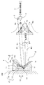
振動可視化素子1は、橋梁やトンネルなどの計測対象物100に取り付けられ、当該計測対象物100に加わった振動を可視化するものである。振動可視化素子1は、図1に示すように、計測対象に固定した筐体11と、光又は電磁波に対して再帰性反射性を有する光学部材12とを備えている。筐体11は固定部の一例である。
The
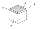
光学部材12は、図2に示すように、互いに略直交するように配置された3枚の鏡を備えている。本第1実施形態において、3枚の鏡のうちの2枚は、固定鏡14で直交している。2枚の固定鏡14の少なくとも1枚は、筐体11に固定され、計測対象物と相対的な位置関係が固定される固定部に含まれる第1の鏡の一例である。3枚の鏡のうちの1枚は、計測対象物100および筐体11に加えられた振動に応じて動く可動鏡13で、第2の鏡の一例である。可動鏡13は光学部材12の可動部に含まれ、固定鏡14に対して振動に応じて相対的に動く。筐体11は、例えば、樹脂、金属またはこれらの組合せで構成される。
As shown in FIG. 2, the
図1に示すように、可動鏡13の鏡面の背面には錘16を付設しており、可動鏡13と錘16とを含む可動部17は、弾性部材の一例であるばね15を介して筐体11に接続されている。計測対象物100が、所定方向、例えば矢印10のように上下方向に振動し、固定部に上下方向の加速度が加わると、可動部に生じる上下方向の慣性力が、ばね15の固定端を回転中心とする力のモーメントとして作用し、可動部17はバネ15の固定端の周りに回転する。このとき、可動鏡13は、点線で示す位置13aと一点鎖線で示す位置13bとの間で振動するように構成されている。所定方向とは、計測対象物の状態変化をモニタリングし易い振動方向であり、例えば、橋梁であれば、上下方向の振動が主であり、長軸方向の振動も観測される。所定方向に合わせて、振動可視化素子の適切に方向に設置できる。なお、ばね15としては、固定部の上下方向など加速度で、可動部が回転し易いばね形状が良く、図1のような薄い板バネや、捩じり梁が好ましい。薄い板バネは、長さ方向には変化し難く、厚み方向の剛性が小さいので、固定端からの距離は変わらずに、板バネが撓むことで可動鏡13は回転するが、長さ方向の剛性が小さいジグザグばねやゴムのような当方的な弾性体は、鏡が平行のまま上下運動し易くなるので好ましくない。
As shown in FIG. 1, a
照明装置2は、振動可視化素子1に向けて光又は電磁波を照射する装置である。照明装置2としては、フリッカーが生じにくい光源、例えば、DC(直流)駆動のLEDなどの装置を用いることが望ましい。なお、照明装置2は、計測対象物100および計測対象物に設置した複数の振動可視化素子を照らす適度な照射角、及び撮影距離や環境に応じた明るさを有するものであればよく、レーザーのような特別な照明装置である必要はない。照明装置2の例としては、例えば、LED照明、HID照明、ハロゲン照明、水銀灯が含まれる。照明装置2は、例えば、白色LEDなどの光源と出射光学系とを備え、出射光学系の出射口から光が出射される。
The
撮影装置3は、図1に示すように、光学部材12によって再帰性反射方向に反射された光又は電磁波を含む映像を撮影する装置である。本第1実施形態において、撮影装置3は、照明装置2の近傍に配置されている。撮影装置3としては、例えば、カメラやレーダーを用いることができる。撮影装置3は、例えば、CMOS又はCCDと入射レンズとを備えたデジタルビデオカメラである。例えば、撮影装置3の入射レンズの中心と照明装置2の光の出射口の中心との間の距離は、近接していることが望ましく、例えば50cm以内であることが望ましく、また、撮影装置と照明装置は、撮影中に互いの位置関係が変わらないように、結合して固定されていることが望ましい。そうすることにより、撮影装置側が、移動体から撮影するときや、風などの外乱で揺れても、振動可視化素子の再帰性により、安定した撮影、計測が可能となる。
As shown in FIG. 1, the photographing
なお、撮影装置3は、反射光の輝度又は電磁波の量の変化を撮影するのに十分なスピードの動画撮影を行えるものであることが望ましい。なお、計測対象物100が橋梁のような大型の構造物である場合、当該構造物の固有振動数は数十Hz以下と遅い。このため、撮影装置3として一般的に普及しているデジタルカメラを用いても、十分なスピードの動画撮影を行うことができる。
Note that it is desirable that the photographing
振動計測装置4は、撮影装置3が撮影した映像に基づいて計測対象物100の振動を計測する装置である。振動計測装置4は、例えば、パーソナルコンピュータにインストールされたソフトウェアによって実現可能である。振動計測装置4は、例えば、ソフトウェアおよび映像データを記憶するメモリとプロセッサとディスプレイとを備える。
The
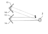
可動鏡13が2枚の固定鏡14に対して直交する位置に位置するとき、可動鏡13又は固定鏡14に入射した光又は電磁波は、図3の実線矢印又は一線鎖線矢印に示すように3回反射され、入射方向に戻る。すなわち、可動鏡13又は固定鏡14に反射された光又は電磁波は、入射方向と逆方向に進行する。以下、この入射方向と逆方向に進行する光又は電磁波の進行方向を「再帰性反射方向」という。この構成によれば、照明装置2から照射された光又は電磁波は、図4に示すように、3枚の鏡の内面に入射する限り、照明装置2に向けて戻るように反射される。
When the
図1において、一点鎖線で示す位置13aは、可動鏡13が固定鏡14に対して直交する位置に位置することを示している。このとき、照明装置2から照射された光又は電磁波は、一点鎖線矢印で示すように、位置13aに位置する可動鏡13及び固定鏡14に反射されて、再帰性反射方向A1に進行する。
In FIG. 1, a
図1において、実線で示す位置13cは、可動鏡13が固定鏡14に対して直交する位置13aから角度θ/2ずれて位置することを示している。すなわち、実線で示す位置13cは、可動鏡13が固定鏡14から90度+θ/2ずれて位置することを示している。このとき、照明装置2から照射された光又は電磁波は、実線矢印で示すように、位置13cに位置する可動鏡13及び固定鏡14に反射されて反射方向B1に進行する。この反射方向B1は、再帰性反射方向A1に対して角度θずれる。
In FIG. 1, a
図1において、点線で示す位置13bは、可動鏡13が固定鏡14に対して直交する位置13aから角度θずれて位置することを示している。すなわち、点線で示す位置13bは、可動鏡13が固定鏡14から90度+θずれて位置することを示している。このとき、照明装置2から照射された光又は電磁波は、点線矢印で示すように、位置13cに位置する可動鏡13及び固定鏡14に反射されて反射方向B2に進行する。この反射方向B2は、再帰性反射方向A1に対して角度2θずれる。
In FIG. 1, a
また、図1では、反射光又は反射電磁波の反射方向A1,B1,B2をそれぞれ一本の線であるものとして記載したが、実際には、可動鏡13及び固定鏡14には僅かな凹凸、配置の誤差、角度のバラツキなどが存在する。このため、反射光又は反射電磁波は、拡散性を有する。この拡散性は、鏡の凹凸、配置の誤差、鏡の角度のバラツキの程度によって異なるが、基本的には、正規分布のような放射強度分布を示す。
In FIG. 1, the reflection directions A1, B1, and B2 of the reflected light or the reflected electromagnetic wave are described as being one line, but actually, the
すなわち、再帰性反射方向A1に反射される反射光又は反射電磁波は、当該再帰性反射方向A1を放射強度のピークとし、当該再帰性反射方向A1から離れるに従い放射強度が減衰するような拡散性を有する。この再帰性反射方向A1に反射される反射光の配光分布を、図1の横方向を放射強度の大きさ、図1の上下方向を方位として概念的に示したものが曲線9aである。同様に、反射方向B1,B2に反射される反射光又は反射電磁波は、当該反射方向B1,B2を放射強度のピークとし、当該反射方向B1,B2から離れるに従い放射強度が減衰するような拡散性を有する。この反射方向B1,B2に反射される反射光の配光分布を、図1の横方向を放射強度の大きさ、図1の上下方向を方位として概念的に示したものが曲線9c,9bである。
That is, the reflected light or the reflected electromagnetic wave reflected in the retroreflective direction A1 has a diffusivity such that the retroreflective direction A1 is a peak of the radiant intensity, and the radiant intensity decreases as the distance from the retroreflective direction A1 increases. Have. The
可動鏡13が初期位置13cに位置するとき、曲線9cに示すように、反射光の配光分布は、反射方向B1をピークとして拡散角φの角度範囲にある。この状態から可動鏡13が初期位置13cから位置13a又は位置13bに振動すると、反射光の配光分布は、曲線9a又は曲線9bのように変化する。
When the
撮影装置3に入射する反射光の放射強度は、各曲線9a,9b,9cと再帰性反射方向A1とが交わる交点の強度となる。すなわち、可動鏡13が位置13aに位置するとき、曲線9aと再帰性反射方向A1とが交わる交点(丸印で示す)が、撮影装置3に入射する反射光の放射強度を示す。また、可動鏡13が位置13cに位置するとき、曲線9cと再帰性反射方向A1とが交わる交点(三角印で示す)が、撮影装置3に入射する反射光の放射強度を示す。また、可動鏡13が位置13bに位置するとき、曲線9bと再帰性反射方向A1とが交わる交点(四角印で示す)が、撮影装置3に入射する反射光の放射強度を示す。従って、可動鏡13が固定鏡14に対して直交する位置13aに位置するとき、撮影装置3に入射する反射光の放射強度が最大になる。一方、可動鏡13が位置13aから角度θずれた位置13bに位置するとき、撮影装置3に入射する反射光の放射強度がほぼゼロになる。
The radiant intensity of the reflected light incident on the
また、反射光の配光分布は、曲線9a,9b,9cに示すように、ピークから拡散角φの半分(φ/2)でゼロとなる。このため、再帰性反射方向A1に対する反射方向B2のズレ角度2θをφ/2と等しくしてもよい。この場合、可動鏡13が位置13aから位置13bに移動するに従い、撮影装置3が検出する輝度が暗くなる。これにより、輝度の変化の範囲をより一層大きくすることができる。
Further, as shown by the
このように、鏡の成す角度の動作範囲を適切に設定することにより、撮影装置3で検出した輝度(反射光又は反射電磁波の放射強度)から、振動を容易に測定することができる。鏡の成す角度の変化の範囲の設定は、振動がゼロのときの可動鏡13の位置を、再帰性反射方向A1の輝度が最大値と最小値との中間値(丁度真ん中の値)となるように設定してもよい。このとき、鏡の成す角度は、90度と90度±φ/4との中間の角度に設定されることになる。その上で、適正な測定範囲を、輝度が最大、最小となる加速度に限定するように使用条件を決めることにより、加速度と輝度とは増減を示すことになり、正確な振動測定が可能となる。
As described above, by appropriately setting the operating range of the angle formed by the mirror, vibration can be easily measured from the luminance (radiation intensity of reflected light or reflected electromagnetic wave) detected by the
以上述べたように、鏡の成す角度の動作範囲の設定を適切に設定することが重要であるが、計測対象物および固定部の所定方向の振動により可動部が振動する現象は、いわゆる強制振動であり、弾性体による可動部の支持構成により、可動部に生じる振幅が変わる。さらに、本発明の場合、固定部に加わる所定方向の加速度を、可動鏡の回転に効率よく変換する必要があり、これらの機構設計が非常に重要となる。 As described above, it is important to appropriately set the operating range of the angle formed by the mirror, but the phenomenon that the movable part vibrates due to the vibration in a predetermined direction of the measurement object and the fixed part is the so-called forced vibration. The amplitude generated in the movable part varies depending on the support structure of the movable part by the elastic body. Furthermore, in the case of the present invention, it is necessary to efficiently convert acceleration in a predetermined direction applied to the fixed portion into rotation of the movable mirror, and these mechanism designs are very important.
本発明者らは、固定部に所定方向の加速度の微小振動を加えた時に、効率よく可動鏡の角度変化に変換できる、可動部の支持構成を、数値シミュレーション等を駆使して鋭意検討した。数値シミュレーションには、ANSYS社の機構シミュレーターであるANASYS Workbench Mechanicalを用いた。また、適宜、実際の素子と計算結果の比較実験を行い、シミュレーション結果が高い精度で実素子と一致することを確認している。 The inventors of the present invention have intensively studied the support structure of the movable part, which can be efficiently converted into the change in the angle of the movable mirror when a minute vibration of acceleration in a predetermined direction is applied to the fixed part, using numerical simulation or the like. For numerical simulations, ANASYS Workbench Mechanical, a mechanism simulator of ANSYS, was used. In addition, a comparison experiment between the actual element and the calculation result is performed as appropriate, and it is confirmed that the simulation result matches the actual element with high accuracy.
図1の振動可視化素子1の可動部12は、板バネからなるばね16で約45度の角度で支持した可動鏡13の背面に錘16を固着した簡単な構造だが、錘を主とする可動部の質量に掛かる上下方向の慣性力により、ばね16が固定部との固定端を支点に撓んで、可動部および可動鏡13が回転して、可動鏡の角度が変わる。可動鏡13と錘16からなる可動部および、可動部を支持するバネ15の形状、これらのサイズ、厚みや素材など、様々に形状パラメータを変えた3Dモデルを作成し、シミュレータ上で固定部に3Hz、50galの上下方向の低周波振動を与え、可動鏡の角度変化量θをシミュレーションした。なお、3Hz、50galは、長さ数百mの大型橋梁で実測した固有振動数と加速度の最大値であり、関連文献の報告結果も概ね同様である為、代表値として設定した。
The
色々な構成を検討しながら、結果を分析した結果、いわゆる力のモーメントのアーム長Lm、すなわち、図1で、回転中心であるばね16の固定端と、力の作用中心である可動部の錘16の重心を通り、上下方向に伸ばした作用線との距離Lmが、可動鏡の角度変化に大きく影響することが分かった。
As a result of analyzing the results while examining various configurations, the arm length Lm of the so-called force moment, that is, the fixed end of the
図5は、横軸に力のモーメントのアーム長Lm、縦軸に、可動鏡の角度変化量θを取って計算結果をプロットしたグラフである。但し、構成パラメータによって、可動部の固有振動数が変わるので、固有振動数を70Hz相当に合わせた場合の角度変化量になるよう補正をしている。すなわち、強制振動では、可動部の固有振動数をf0、固定部への入力振動周波数をfとすると、可動部に生じる振動の振幅aは、1/(f0 2−f2)に比例するので、シミュレーションで得た固有振動数f0 ヘルツと角度変化量θ°を、θ‘=θ×(f0/70)2として算出し、θ’を70Hz相当の角度変化量としている。 FIG. 5 is a graph in which the calculation result is plotted by taking the arm length Lm of the moment of force on the horizontal axis and the angle change amount θ of the movable mirror on the vertical axis. However, since the natural frequency of the movable part varies depending on the configuration parameters, the correction is made so that the amount of change in angle is the same as when the natural frequency is adjusted to 70 Hz. That is, in forced vibration, if the natural frequency of the movable part is f 0 and the input vibration frequency to the fixed part is f, the amplitude a of the vibration generated in the movable part is proportional to 1 / (f 0 2 −f 2 ). since the natural frequency f 0 Hz and angle variation theta ° obtained by simulation, theta '= calculated as θ × (f 0/70) 2, θ' is the the amount of angular change corresponding 70 Hz.
橋梁などの大型構造物では、0.5〜50Hz程度の周波数帯で50gal以下の微小振動をモニタリングする必要がある。固有振動数を70Hz相当に合わせたのは、50Hz程度の振動でも共振を避けられ、かつ、感度がなるべく高くなる値として設定した。固有振動数が70Hz以上の時、0.5Hzの時の振幅aとf=50Hzの時の振幅aの比率を2倍以下に抑えられるので、共振を回避して、周波帯域内全体での測定が可能である。70Hzより低いと共振点が近づくので、急激に振幅が大きくなるので好ましくない。 In a large structure such as a bridge, it is necessary to monitor a minute vibration of 50 gal or less in a frequency band of about 0.5 to 50 Hz. The natural frequency is set to a value corresponding to 70 Hz so that resonance can be avoided even with a vibration of about 50 Hz and the sensitivity is as high as possible. When the natural frequency is 70 Hz or more, the ratio of the amplitude a at 0.5 Hz to the amplitude a at f = 50 Hz can be suppressed to twice or less, so that resonance can be avoided and measurement in the entire frequency band can be performed. Is possible. If the frequency is lower than 70 Hz, the resonance point approaches, so the amplitude increases rapidly, which is not preferable.
図5のグラフで、白抜き□のマーカーが、図1の構成での計算結果である。黒い菱型マークは、後述の第2実施形態で説明する図10の構成での計算結果である。いずれの場合も、力のモーメントアーム長Lmが小さいほど、可動鏡の角度変化θは大きくなり、対数グラフ上でほぼ直線上に並んでいるのが分かる。計算した構成は、素材としてポリエチレンなどの樹脂やステンレスや鋼、シリコンなどを設定し、固有振動数を概ね70Hz近辺に合うように、ばね16の板厚や錘の重さ等を調整した。例えば、サイズの縮尺を変えてLmを1/2に小さくした場合には、固有振動数は概ね2倍になるので、ばねの厚みを1/√2にする、など定性的な傾向を基に、素材によって加工可能な寸法の範囲、例えばバネの厚みなら1ミクロンから数百ミクロンでパラメータ調整を行ったモデルを作成した。素材や形状を各種変えて計算したが、驚いたことに、いずれの場合でもLmとθの関係は、概ね同様の傾向を示した。
In the graph of FIG. 5, the open square markers are the calculation results in the configuration of FIG. The black rhombus mark is a calculation result in the configuration of FIG. 10 described in the second embodiment described later. In either case, it can be seen that the smaller the moment arm length Lm of the force is, the larger the angle change θ of the movable mirror is, and it is arranged on a substantially straight line on the logarithmic graph. In the calculated configuration, a resin such as polyethylene, stainless steel, steel, silicon, or the like is set as a material, and the plate thickness of the
次に、可動鏡の角度変化量が、正確な振動計測をする為にどの程度必要かを考察する。上述したように、撮影装置で可動鏡の振動を反射光の輝度変化として検出するには、反射光の拡散角φの半角と、可動鏡の角度変化θの対応していることが望ましい。もし、可動鏡の角度変化θが非常に小さい場合には、拡散角φを同程度に小さくすれば、計測は可能である。しかし、反射光の拡散角φは、鏡の凹凸などによって決定され、加工精度の限界以下には小さくはできない。一般的なガラス鏡の平坦性は、25mm角でのうねりの高さで3ミクロン程度であり、角度で換算すると1分程度となり、通常は、拡散角φの半角は1分よりは大きくなると考えてよい。したがって、可動鏡の角度変化は、加工限界の目安の角度1分よりも大きいことが、S/N比の良い測定の条件となる。図 のグラフに、角度1分のレベルを破線の直線で示したが、可動鏡の角度変化θが1分より大きくなるのは、モーメントアーム長Lmが4度強の場合となる。従って、力のモーメント長Lmが4度より小さいことが望ましい構成と言える。 Next, the degree to which the angle change amount of the movable mirror is necessary for accurate vibration measurement will be considered. As described above, in order to detect the vibration of the movable mirror as the luminance change of the reflected light in the photographing apparatus, it is desirable that the half angle of the diffusion angle φ of the reflected light corresponds to the angle change θ of the movable mirror. If the angle change θ of the movable mirror is very small, the measurement can be performed by reducing the diffusion angle φ to the same extent. However, the diffusion angle φ of the reflected light is determined by the unevenness of the mirror and cannot be reduced below the limit of processing accuracy. The flatness of a general glass mirror is about 3 microns in terms of the height of the swell at a 25 mm square, and it is about 1 minute when converted to an angle. Normally, the half angle of the diffusion angle φ is considered to be larger than 1 minute. It's okay. Therefore, a condition for measurement with a good S / N ratio is that the angle change of the movable mirror is larger than an angle of 1 minute, which is a guideline for the processing limit. In the graph of the figure, the level of 1 minute angle is shown by a broken line, but the angle change θ of the movable mirror becomes larger than 1 minute when the moment arm length Lm is slightly over 4 degrees. Therefore, it can be said that it is desirable that the moment length Lm of the force is smaller than 4 degrees.
さらに、計測可能帯域を拡大するために、固有振動数f0をさらに大きくする場合には、固有振動数70Hzの場合のLm=4mmを基準に、周波数の2乗に反比例させて算出すればよい。すなわち、可動部の固有振動数f0の時、力のモーメントアーム長Lmは(70/f0)2×4mm以下であることが構成要件となる。 Furthermore, when the natural frequency f0 is further increased in order to expand the measurable bandwidth, it may be calculated in inverse proportion to the square of the frequency on the basis of Lm = 4 mm when the natural frequency is 70 Hz. That is, when the natural frequency f0 of movable portions, the moment arm length Lm forces a configuration requirement that is (70 / f 0) 2 × 4mm or less.
このような構成を採用した本発明の振動可視化素子は、図5のグラフの示したように、3Hzの低周波から高次振動を含む50Hzまでの周波数帯域を計測可能であり、特に、大型構造物等の振動のモニタリングに適した振動可視化素子である。 The vibration visualization element of the present invention adopting such a configuration can measure a frequency band from a low frequency of 3 Hz to 50 Hz including high-order vibrations as shown in the graph of FIG. It is a vibration visualization element suitable for monitoring vibrations of objects.
本第1実施形態によれば、光学部材12が再帰性反射性を有しているので、1つの照明装置2で複数の光学部材12に光又は電磁波を照射することで、当該複数の光学部材12に反射された反射光又は反射電磁波を1つの撮影装置3で受けることができる。すなわち、計測対象物100に複数の振動可視化素子1を貼り付け、それらの振動可視化素子1に照明装置2から光又は電磁波を照射することで、それらの振動可視化素子1により反射された反射光又は反射電磁波の放射強度の変化を撮影装置3で同時に計測することができる。これにより、計測対象物100の全体の振動の状態をより短時間かつ詳細に分析することが可能になり、計測対象物100に加わる振動10を可視化することができる。
According to the first embodiment, since the
また、本第1実施形態によれば、振動可視化素子1が電力を消費する部品は含まないので、電池を交換する必要性を無くして、メンテナンス回数をより少なくすることができる。また、振動可視化素子1の製造コストを安くすることができ、腐食などの劣化を抑えることができる。
Further, according to the first embodiment, since the
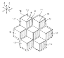
なお、本第1実施形態では、振動可視化素子1が、3枚の鏡を備える光学部材12を1つ備えるものとしたが、本開示はこれに限定されない。振動可視化素子1は、例えば、図6A及び図6Bに示すように、光学部材12を複数敷き詰めるように備えてもよい。この構成によれば、光又は電磁波の反射面積を増加させて、計測対象物100の振動計測をより正確に行うことができる。
In the first embodiment, the
なお、図6Aは、複数の光学部材12のそれぞれの可動鏡13をZ方向に振動するように配置した図である。図6Aに示す振動可視化素子1Aによれば、Z方向の振動に対して感度を有することができる。また、図6Bは、複数の光学部材12のそれぞれの可動鏡13をY方向に振動するように配置した図である。図6Bに示す振動可視化素子1Bによれば、Y方向の振動に対して感度を有することができる。
FIG. 6A is a diagram in which the
また、図6Aに示す振動可視化素子(第1振動可視化素子の一例)1Aと、図6Bに示す振動可視化素子(第2振動可視化素子の一例)1Bの前方(照明装置2側)にそれぞれに異なる色のカラーフィルタを配置してもよい。互いに異なる色のカラーフィルタは、透過波長帯が異なる第1及び第2のカラーフィルタの例である。第1のカラーフィルタは、少なくとも振動可視化素子1Aに入射する光又は電磁波の光路上又は振動可視化素子1Aから出射される反射光又は反射電磁波の光路上に配置されてもよい。第2のカラーフィルタは、少なくとも振動可視化素子1Aに入射する光又は電磁波の光路上又は振動可視化素子1Aから出射される反射光又は反射電磁波の光路上に配置されてもよい。例えば、振動可視化素子1Aの前方に赤色のカラーフィルタを配置する一方で、振動可視化素子1Bの前方に青色のカラーフィルタを配置してもよい。
Further, the vibration visualization element (an example of the first vibration visualization element) 1A shown in FIG. 6A is different from the vibration visualization element (an example of the second vibration visualization element) 1B shown in FIG. 6B (on the
この構成によれば、振動可視化素子1Aの可動鏡13がZ方向に振動したとき、振動可視化素子1Aが赤色に点滅して見える。この振動可視化素子1Aを計測対象物100に取り付けることにより、計測対象物100のZ方向の振動を計測することが可能になる。また、前記構成によれば、振動可視化素子1Bの可動鏡13がY方向に振動したとき、振動可視化素子1Bが青色に点滅して見える。この振動可視化素子1Bを計測対象物100に取り付けることにより、計測対象物100のZ方向の振動を計測することが可能になる。また、それらの振動可視化素子1A,1Bを計測対象物100の全体に分散して配置すれば、計測対象物100の2軸方向(Y,Z方向)の振動を独立して計測することが可能になる。
According to this configuration, when the
また、X方向の振動に対して感度を有する振動可視化素子を作成し、当該振動可視化素子の前方に赤色及び青色とは異なる色(例えば、緑色)のカラーフィルタを配置してもよい。この振動可視化素子と振動可視化素子1A,1Bを、計測対象物100の全体に分散して配置すれば、計測対象物100の3軸方向(X,Y,Z方向)の振動を独立して計測することが可能になる。
Alternatively, a vibration visualization element having sensitivity to vibration in the X direction may be created, and a color filter of a color different from red and blue (for example, green) may be disposed in front of the vibration visualization element. If this vibration visualization element and the
なお、光学部材12が風や腐食などの計測対象物100の振動以外の要因の影響を受けた場合には、計測対象物100の振動を正確に計測することができない。このため、光学部材12を覆うようにカバーを設けるなどして、光学部材12を封止することが望ましい。また、光学部材12又はカバーの表面は、防汚表面処理などが施されることが望ましい。
Note that when the
なお、振動可視化素子1A,1Bの形状は、図6A及び図6Bに示す形状に限定されるものではなく、種々の形状とすることができる。例えば、振動可視化素子1A,1Bの形状を三角形や四角形などの図形や、文字にしてもよい。この場合、振動可視化素子1Aと振動可視化素子1Bとで形状を異ならせ、計測対象物100の全体に分散して配置すれば、計測対象物100の2軸方向の振動を独立して計測することが可能になる。また、X方向の振動に対して感度を有する振動可視化素子を、振動可視化素子1A,1Bの形状と異なる形状に形成してもよい。この振動可視化素子と振動可視化素子1A,1Bを、計測対象物100の全体に分散して配置すれば、計測対象物100の3軸方向(X,Y,Z方向)の振動を独立して計測することが可能になる。
Note that the shapes of the
また、本第1実施形態では、光学部材12が備える3枚の鏡のうちの1枚を可動鏡13とし、2枚を固定鏡14としたが、本開示はこれに限定されない。例えば、光学部材12が備える3枚の鏡のうちの2枚を可動鏡13とし、1枚を固定鏡14としてもよい。この場合、2枚の可動鏡13は、固定鏡14の2辺に弾性部材(例えばヒンジ及びアーム角度が90度のトーションばね)で接続されていてもよい。なお、2枚の可動鏡13が互いに直接衝突しないように、2枚の可動鏡13と固定鏡14との間に隙間が設けられている。2枚の可動鏡13が互いに直接衝突しないように、2枚の可動鏡13に緩衝材を設けてもよい。この構成によれば、2軸方向の振動に対して感度を有することができる。但し、この構成では、1台の撮影装置3では、振動方向を検出することが困難である。この場合、2台以上の撮影装置3を設置することができる。例えば、再帰性反射方向に対してZ方向にずれて進行方向B1に進む光又は電磁波を検出するために、図1に示す撮影装置3の上方にもう1台の撮影装置3を設置してもよい。この構成によれば、Z方向の振動成分を同定でき、撮影装置3の検出信号からZ成分を除くことで、Y方向の成分を抽出することができる。
In the first embodiment, one of the three mirrors included in the
また、本第1実施形態では、光学部材12が備える3枚の鏡を備えるものとしたが、本開示はこれに限定されない。例えば、光学部材12は、1枚の可動鏡13と1枚の固定鏡14の2枚の鏡を備えるものであってもよい。この場合、光学部材12に対して斜めから入射した光又は電磁波に対して再帰性反射することはできないが、光学部材12に対して垂直に入射した光又は電磁波に対しては再帰性反射することができる。
In the first embodiment, the three mirrors included in the
また、図1〜図6Bでは、可動鏡13及び固定鏡14の形状を矩形として示したが、本開示はこれに限定されない。例えば、可動鏡13及び固定鏡14の形状は三角形であってもよい。
Moreover, in FIGS. 1-6B, although the shape of the
なお、可動鏡13、固定鏡14、及びばね15は、例えば、ステンレスなどの金属箔(数μmから100μm程度の厚さ)をレーザなどで切断、折り曲げ、接着、溶接などで加工することにより作成することができる。また、可動鏡13及び固定鏡14は、例えば、プラスチックの金型成形で本体を形成し、当該本体の表面にアルミニウムなどを蒸着することにより鏡面を形成してもよい。また、ばね15の一端部および固定鏡14を支持する振動可視化素子1の筐体11は、プラスチックの金型成形などにより正確に角度、形状を作成することが望ましい。
The
なお、照明装置2が電磁波を照射するものである場合、当該電磁波は光よりも波長の長い電磁波であることが望ましい。また、この場合、可動鏡13及び固定鏡14のフラットな状態の鏡面のサイズは、電磁波の波長より大きいことが望ましい。これにより、照明装置2が光を照射する場合と同様に取り扱うことができる。なお、波長の長い電磁波を用いた場合、より離れた場所、例えば衛星からでも振動計測が可能となる。
In addition, when the illuminating
次に、本第1実施形態に係る振動計測システムを用いた振動計測方法について説明する。図7は、当該振動計測方法のフローチャートである。ここでは、図8に示すように、計測対象物100が橋梁であるとする。また、以下では説明を簡単にするため、照明装置2は光のみを照射するものとし、電磁波についての説明は省略する。
Next, a vibration measurement method using the vibration measurement system according to the first embodiment will be described. FIG. 7 is a flowchart of the vibration measurement method. Here, as shown in FIG. 8, it is assumed that the
まず、ステップS1では、計測対象物100に複数の振動可視化素子1を取り付ける。
First, in step S <b> 1, a plurality of
なお、振動可視化素子1は、計測対象物100の種類や構造に依存するが、計測対象物100の劣化し易い部分を中心として、計測対象物100の全体の振動モードが推定できるように分散させて設置することが望ましい。本第1実施形態に係る振動可視化素子1は、無線発信機やCPU等の消費電力が大きい部品を含まないので、計測対象物100に一旦取り付ければ長期間使用することができる。このため、振動可視化素子1が計測対象物100から外れないように、しっかり固定することが望ましい。
Although the
次に、ステップS2では、図8に示すように、計測対象物100に向けて照明装置2から光を照射し、振動可視化素子1の光学部材12によって再帰性反射方向に反射された光を含む映像を撮影装置3により撮影する。
Next, in step S <b> 2, as shown in FIG. 8, the
なお、ステップS2において、撮影装置3により撮影する映像は、複数の振動可視化素子が計測対象物100の振動に応じて明滅する映像となる。計測対象物100が橋梁である場合、橋梁の振動は、主に、Z方向(即ち、鉛直方向)とY方向(即ち、橋の長軸方向)の2軸方向の成分からなることが知られている。このため、図6Aに示す振動可視化素子1Aと図6Bに示す振動可視化素子1Bとを、橋梁の全体に分散して配置することで、Z方向とY方向の2軸方向の振動計測を行うことができる。
Note that in step S <b> 2, an image captured by the
次に、ステップS3では、振動計測装置4が、撮影装置3が撮影した映像に基づいて計測対象物100の振動を計測する。例えば、振動計測装置4は、撮影装置3により撮影した映像の各フレームの画像から特定位置の画素の輝度変化をサンプリングするなどの画像処理を行う。これにより、映像に映っている複数の振動可視化素子1の振動波形を抽出することができ、計測対象物100の複数箇所の振動の周波数、位相、及び振幅を計測することができる。
Next, in step S <b> 3, the
本第1実施形態に係る振動計測方法によれば、計測対象物100の振動に応じて複数の振動可視化素子1が明滅するので、計測対象物100の当該振動を目視により観測することもできる。また、振動可視化素子1に再帰性反射される光は、高い指向性を有しているので、例えば、計測対象物100から数百m離れた位置からでも観測することが可能である。また、撮影装置3自体が微振動するなどして多少の焦点のボケやブレが生じた場合であっても、反射光の輝度の変化を検知することができれば、計測対象物100の振動を計測することができる。したがって、本第1実施形態に係る振動計測方法は、従来の方法に比べてノイズや環境の変化に対して強い計測方法であると言える。
According to the vibration measurement method according to the first embodiment, since the plurality of
なお、振動計測装置4は、計測した計測対象物100の振動データを蓄積して記憶する記憶部と、文字や音等により異常を報知する報知部を備えることが望ましい。記憶部は、例えば、半導体メモリである。報知部は、例えば、モニタ及び/又はスピーカである。この構成によれば、記憶部に蓄積された過去の振動データと今回計測した振動データとを比較することで、計測対象物100の異常箇所及び程度を検出することが可能になる。また、当該検出結果に基づいて報知部が管理者に異常を報知することで、計測対象物100に対する早期のメンテナンスを可能にすることができる。
Note that the
なお、ステップS2において、照明装置2から照射する光は、計測対象物100の振動周波数付近で周期的に点滅させてもよい。この場合、ストロボ撮影により、計測対象物100の振動周波数とストロボの周波数との差分周波数がうねるように振動するので、当該うねりから振動数の詳細な周波数の同定を行うことが可能になる。
In step S <b> 2, the light emitted from the
なお、照明装置2及び撮影装置3は、計測対象物100から離れた位置で固定されてもよいし、車やヘリコプターなどの移動体に設置されてもよい。照明装置2及び撮影装置3を計測対象物100から離れた位置に固定する場合は、例えば、安全や演出のために橋梁を照らしている照明装置の横に設置してもよい。これにより、定点観測が行える。
In addition, the illuminating
また、照明装置2及び撮影装置3を車に設置する場合は、車の重量や速度を一定にしておくことで、車の重量が刺激となり、計測対象物100の振動を安定して計測することができる。なお、車などの移動体に搭載された撮影装置3で撮影した場合には、撮影した映像の中で振動可視化素子1の位置は移動するが、一旦位置を同定すれば、画像処理で特徴を抽出して追跡することは容易である。
Moreover, when installing the illuminating
なお、一般的に普及しているデジタルカメラで可視光による撮影を行う場合は、太陽光による影響が少ない状況、例えば、夜間に撮影を行う方がよい。この場合、撮影装置3が撮影した映像には、例えば、図9に示すように、照明装置2により薄暗く照らされた計測対象物100と、再帰性反射により明るく光る振動可視化素子1と、街灯やビルの明かりなどの背景が含まれる。この映像から複数の振動可視化素子1の位置を抽出する必要がある。この場合、例えば、振動計測の開始時又は振動計測中において、照明装置2の光を点滅させ、振動可視化素子1に反射された光と照明装置2の光とが同期して点滅する部分を特定することにより、振動可視化素子1の位置を同定することが可能である。すなわち、照明装置2から複数の振動可視化素子1に光を点滅させて照射し、撮影装置によって反射光を含む映像を撮影する。撮影した映像において、照明装置2からの光の点滅と同期して点滅する周囲よりも明るい部分を特定することにより、複数の振動可視化素子の位置を同定することができる。
In addition, when photographing with visible light is performed with a digital camera that is generally spread, it is better to perform photographing in a situation where the influence of sunlight is small, for example, at night. In this case, for example, as shown in FIG. 9, the image captured by the
なお、照明装置2として、水分子の吸収により、地上での太陽光のスペクトルが弱い波長域、例えば1.35μm付近や1.15μm付近の光を発光するLEDを使用してもよい。この場合、太陽光による影響を少なくすることができ、昼間でもSN比の高い振動計測が可能になる。
In addition, you may use LED which light-emits the light of the wavelength range where the spectrum of sunlight on the ground is weak, for example, 1.35 micrometer vicinity and 1.15 micrometer vicinity by absorbing water molecule as the illuminating
(第2実施形態)
図10は、本開示の第2実施形態に係る振動計測システムの概略構成図である。
(Second Embodiment)
FIG. 10 is a schematic configuration diagram of a vibration measurement system according to the second embodiment of the present disclosure.
本第2実施形態に係る振動計測システムが前記第1実施形態に係る振動計測システムと異なる点は、可動鏡13及びばね15、錘16に代えて、複数の可動鏡21、複数の可動鏡21と固定部を繋ぐ第1の捩じり梁20、複数の可動鏡21と一つの錘23を繋ぐ第2の捩じり梁22とを備えている点である。他の部分は第1実施形態と同様である。
The vibration measurement system according to the second embodiment is different from the vibration measurement system according to the first embodiment in that instead of the
図11は、図10の振動可視化素子の可動部を拡大した斜視図である。複数の可動鏡21は、細長く形成され、それぞれ平行に配置されている。複数の可動鏡21の各一端部は、第2の捩じり梁22と柱状の連結部材24を介して錘23に連結されている。可動鏡21は、第2の鏡の一例である。複数の可動鏡21は第1の捩じり梁20で支持され、連結部26でフレーム25に繋がっている。フレーム25は筐体11と繋がる固定部である。計測対象物100が矢印10の上下方向に振動したとき、錘23には慣性力が生じ、錘23も上下方向に振動する。このとき、捩じり梁20を支点に、図11において点線21pに示すように、各可動鏡21が捩じり梁20を中心に回転する。これにより、各可動鏡21の固定鏡14に対する角度が可変する。
FIG. 11 is an enlarged perspective view of the movable part of the vibration visualization element of FIG. The plurality of
共通の錘を複数の回転体に連結すると、連結部が固いと回転が阻害されてしまうが、図10,11のように、共通錘23と可動鏡の結合部にも捩じり梁を設けて連結部を柔軟にすることで、複数の可動鏡21は各々の回転軸である第1の捩じり梁20の周りに回転できる。錘は上下に振動し、応力がほぼ第1と第2の捩じり梁のみに分散されることで、効率よく回転が生じる。第1実施形態では錘16と可動鏡が一体化していたのが、第2実施形態では共通の錘が捩じり梁で柔らかく結合していることで、錘の慣性力の作用中心は、連結部である第2の捩じり梁となる。このため、作用中心が1点に集中するので、錘のサイズに制限が無くなり、設計の自由度が増す。
When a common weight is connected to a plurality of rotating bodies, the rotation is hindered if the connecting portion is hard. However, as shown in FIGS. 10 and 11, a torsion beam is also provided at the joint between the
回転軸である第1の捩じり梁と、作用中心の第2の捩じり梁を通る作用線との距離をLmとして、第1実施形態でも説明したように、力のモーメントアーム長Lmと可動鏡21の角度変化量θの特性をシミュレーションで計算した。図5のグラフの黒菱型マークのようにLmが小さいほど角度変化量θは大きくなり、第1実施形態の場合と同じ傾向を示し、Lmを4mm以下とすることで大型構造物の微振動の計測できる。図11のように捩じり梁を用いることで、モーメントアーム長Lmを小さくし易くなる。MEMSなどで用いる半導体プロセスなどを用いれば、Lmを数十ミクロン程度にすることも容易であり、50galよりも2ケタ程度小さい極微小な振動も検出可能になるし、より周波数の高い振動を検出することも可能となる。また、Lmを小さくしたときの固有振動数を下げるために錘を重くすることも図11の構成では容易になるという特長がある。
As described in the first embodiment, the distance between the first torsion beam as the rotation axis and the action line passing through the second torsion beam at the action center is Lm, as described in the first embodiment. The characteristics of the angle change amount θ of the
本第2実施形態によれば、計測対象物100の振動が微小であっても、各可動鏡21の固定鏡14に対する角度を大きく変化させることができる。これにより、計測対象物100が固有振動数の低い大型構造物であっても、その振動をより感度良く計測することができる。
According to the second embodiment, even if the vibration of the
(実施例)
実施例に係る振動可視化素子は、前記第1実施形態に係る振動可視化素子1と同様の構成を有するように構成した。すなわち、実施例に係る振動可視化素子は、可動鏡13と錘16、固定鏡14と、ばね15とを備えている。実施例に係る振動可視化素子において、可動鏡13、固定鏡14、ばね15とは、精密切削加工による金型を作成し、アクリル樹脂で注型することにより樹脂成形した。可動鏡13と固定鏡14とは、アルミを蒸着して鏡面を備えるように構成した。可動鏡13の厚みは25ミクロンと薄くし、可動鏡13の背面側に鋼の錘を顕微鏡下で位置を調節して接着し、Lmを2mmとなるよう調整した。また、ばねの厚さなどを調整して、可動部の固有振動数が70Hz程度になるように構成した。
(Example)
The vibration visualization element according to the example is configured to have the same configuration as the
また、固定鏡14の裏面には、可動鏡13と固定鏡14とが成す角度を微調整できるように調整機構を設けた。この調整機構により、振動を加えない状態における可動鏡13と固定鏡14とが成す角度を、撮影装置3の輝度が最大となる角度と撮影装置3の輝度がほぼゼロになる角度との中間の角度になるように調整した。
An adjustment mechanism is provided on the back surface of the fixed
このような構成を有する実施例に係る振動可視化素子を加振器に取り付け、信号発生器から3.0Hzのサイン波を加振器に入力して振動を発生させた。当該振動と同一条件の振動を市販のMEMS型加速度計で計測したところ、加速度のピーク値が±10galのサイン波の振動が加振器より発生されていることを確認した。 The vibration visualization element according to the example having such a configuration was attached to the vibrator, and a vibration was generated by inputting a 3.0 Hz sine wave from the signal generator to the vibrator. When vibration under the same conditions as the vibration was measured with a commercially available MEMS accelerometer, it was confirmed that a vibration of a sine wave having an acceleration peak value of ± 10 gal was generated from the vibrator.
実施例において、撮影装置3は、市販のデジタルカメラを使用した。照明装置2は、白色のLEDビデオライトを使用し、撮影装置3の上部の装着部に装着した。その後、実施例に係る振動可視化素子に照明装置2からLED光を照射しながら、撮影装置3により120フレーム/秒の動画を撮影した。
In the embodiment, the photographing
撮影された動画の映像には、実施例に係る振動可視化素子が3Hzで明暗を繰り返す様子が撮影されていた。当該映像からフレーム毎に実施例に係る振動可視化素子の部分の画素領域のデータを抽出し、当該画素領域のRGBの輝度を積算して、実施例に係る振動可視化素子の輝度値を得た。図12は、このようにして得られた輝度値の変化を示すグラフである。 In the captured video image, the vibration visualizing element according to the example repeats light and dark at 3 Hz. Data of the pixel region of the vibration visualization element according to the example was extracted from the video for each frame, and the luminance values of the vibration visualization element according to the example were obtained by integrating the RGB luminances of the pixel region. FIG. 12 is a graph showing changes in luminance values obtained in this way.
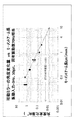
図12に示すように、輝度値の変化を示す波形120は、僅かにノイズがあるものの、3Hzのサイン波形となっている。なお、ノイズの大きさは、市販のMEMS型加速度計よりも小さかった。また、図12の波形120に対してFFT(高速フーリエ変換)によりパワースペクトルを計算したところ、図13に示すように、正確に3.0Hzに単一のピークを有することを確認した。これにより、振動の波形を計測できることが確認された。また、加振器への入力信号を変えて、振動の振幅、周波数を変えると、それに応じて輝度値も変化し、50Hz程度までの周波数帯域の振動強度に対応する振動の波形を計測することができた。
As shown in FIG. 12, a
なお、Lmを大きくしていくと、輝度変化が小さくなる傾向が確認された。Lmが4mmでは3Hzで±50gal程度の振動は観測できたが、Lmが5mmを超えると、さらに輝度変化が殆ど分からなくなった。 In addition, the tendency for a luminance change to become small was confirmed as Lm was enlarged. When Lm was 4 mm, a vibration of about ± 50 gal at 3 Hz could be observed, but when Lm exceeded 5 mm, the luminance change was hardly understood.
以上のようにして、本開示に係る振動可視化素子を計測対象物に貼り付けることで、遠方から振動計測を行えることを確認した。 As described above, it was confirmed that vibration measurement can be performed from a distance by attaching the vibration visualization element according to the present disclosure to a measurement object.
なお、前記様々な実施形態のうちの任意の実施形態を適宜組み合わせることにより、それぞれの有する効果を奏するようにすることができる。 It is to be noted that, by appropriately combining any of the various embodiments, the effects possessed by them can be produced.
本開示は、添付図面を参照しながら幾つかの実施の形態に関連して充分に記載されているが、この技術に熟練した人々にとっては種々の変形や修正は明白である。そのような変形や修正は、添付した請求の範囲による本開示の範囲から外れない限りにおいて、その中に含まれると理解されるべきである。 Although the present disclosure has been fully described in connection with some embodiments with reference to the accompanying drawings, various variations and modifications will be apparent to those skilled in the art. Such changes and modifications are to be understood as included within the scope of the present disclosure as set forth in the appended claims.
本開示は、計測対象物全体の振動計測をより短時間で行うことを可能にするとともに、メンテナンスの回数をより少なくすることができるので、橋梁やトンネルなどの公共の構造物のみならず、機械、ビルなどの健全度の評価、監視に有用である。また、振動可視化素子のサイズを大きくすれば、航空機や衛星から計測対象物全体の振動計測を行うこともでき、地震の計測、監視にも応用可能である。 The present disclosure makes it possible to perform vibration measurement of the entire measurement object in a shorter time and to reduce the number of maintenance, so that not only public structures such as bridges and tunnels, but also machinery It is useful for evaluating and monitoring the soundness of buildings. In addition, if the size of the vibration visualization element is increased, vibration measurement of the entire measurement object can be performed from an aircraft or satellite, and it can be applied to earthquake measurement and monitoring.
1 振動可視化素子
2 照明装置
3 撮影装置
4 振動計測装置
11 筐体
12 光学部材
13 可動鏡
14 固定鏡
15 ばね(弾性部材)
16 錘
17 可動部
20 第1の捩じり梁(回転軸)
21 可動鏡
22 第2の捩じり梁(作用中心)
23 錘
24 ばね(弾性部材)
25 連結部
100 計測対象物
DESCRIPTION OF
16
21
23
25 connecting
Claims (7)
前記光学部材は、それぞれの鏡面が互いに直交する、第1の鏡、第2の鏡、及び第3の鏡を備え、
前記第1の鏡は、前記固定部に含まれ、
前記可動部は、前記第2の鏡と錘を有し、前記可動部は弾性部材で前記固定部に支持され、
前記固定部に所定方向の加速度が加わることにより、前記可動部が前記弾性部材の固定部への固定端の周りに回転して、前記第2の鏡と前記第1の鏡の角度が変化することによって、光又は電磁波の反射方向を変化させ、再帰性反射方向に出射する反射光の輝度又は反射電磁波の量を変化させる振動可視化素子において、
前記加速度により可動部に生じる慣性力の作用中心を通る前記所定方向の作用線と、前記固定端を通る前記回転の回転軸との距離が4mm以下である、振動可視化素子。 An optical member that retroreflects light or electromagnetic waves, the optical member having a fixed portion in which a relative positional relationship with a measurement object is fixed, and a movable portion that is movably supported with respect to the fixed portion. Prepared,
The optical member includes a first mirror, a second mirror, and a third mirror whose mirror surfaces are orthogonal to each other,
The first mirror is included in the fixed part,
The movable part has the second mirror and a weight, and the movable part is supported by the fixed part with an elastic member,
When acceleration in a predetermined direction is applied to the fixed portion, the movable portion rotates around a fixed end of the elastic member to the fixed portion, and the angle between the second mirror and the first mirror changes. In the vibration visualization element that changes the reflection direction of light or electromagnetic waves, and changes the luminance of reflected light or the amount of reflected electromagnetic waves emitted in the retroreflection direction,
The vibration visualization element, wherein a distance between the action line in the predetermined direction passing through the action center of the inertia force generated in the movable portion by the acceleration and the rotation axis of the rotation passing through the fixed end is 4 mm or less.
計測対象物に設置された、前記複数の振動可視化素子に向けて光又は電磁波を照射する照明装置と、
前記計測対象物と、前記複数の振動可視化素子と、を含む映像を撮影する撮影装置と、
前記撮影装置が撮影した前記映像における、前記複数の振動可視化素子の反射光の輝度又は反射電磁波の量の変化に基づいて、前記複数の振動可視化素子のそれぞれにおける前記固定部と前記可動部との相対的な位置関係の変化を計測する振動計測装置と、
を備える、振動計測システム。 A plurality of vibration visualization elements according to any one of claims 1 to 5;
An illumination device that is installed on a measurement object and irradiates light or electromagnetic waves toward the plurality of vibration visualization elements;
An imaging device that captures an image including the measurement object and the plurality of vibration visualization elements;
Based on a change in luminance of reflected light or amount of reflected electromagnetic waves of the plurality of vibration visualization elements in the video imaged by the imaging device, the fixed portion and the movable portion of each of the plurality of vibration visualization elements A vibration measurement device that measures changes in relative positional relationship;
A vibration measurement system comprising:
前記一つ又は複数の振動可視化素子を前記計測対象物に取り付け、
前記一つ又は複数の振動可視化素子に前記光又は前記電磁波を照射しながら、当該一つ又は複数の振動可視化素子それぞれの前記一つ又は複数の光学部材によって前記再帰性反射方向に出射された前記反射光又は前記反射電磁波を含む映像を撮影し、
前記撮影した映像に基づいて前記計測対象物の振動を計測する、 振動計測方法。 A method for measuring vibration of the measurement object using one or a plurality of vibration visualization elements according to any one of claims 1 to 5,
Attaching the one or more vibration visualization elements to the measurement object,
The one or more vibration visualization elements are emitted in the retroreflection direction by the one or more optical members of the one or more vibration visualization elements while irradiating the light or the electromagnetic wave to the one or more vibration visualization elements. Shooting images containing reflected light or reflected electromagnetic waves,
A vibration measurement method for measuring vibration of the measurement object based on the photographed video.
Priority Applications (1)
| Application Number | Priority Date | Filing Date | Title |
|---|---|---|---|
| JP2016198599A JP2018059855A (en) | 2016-10-07 | 2016-10-07 | Vibration visualization element, vibration measurement system |
Applications Claiming Priority (1)
| Application Number | Priority Date | Filing Date | Title |
|---|---|---|---|
| JP2016198599A JP2018059855A (en) | 2016-10-07 | 2016-10-07 | Vibration visualization element, vibration measurement system |
Publications (1)
| Publication Number | Publication Date |
|---|---|
| JP2018059855A true JP2018059855A (en) | 2018-04-12 |
Family
ID=61908856
Family Applications (1)
| Application Number | Title | Priority Date | Filing Date |
|---|---|---|---|
| JP2016198599A Pending JP2018059855A (en) | 2016-10-07 | 2016-10-07 | Vibration visualization element, vibration measurement system |
Country Status (1)
| Country | Link |
|---|---|
| JP (1) | JP2018059855A (en) |
Cited By (1)
| Publication number | Priority date | Publication date | Assignee | Title |
|---|---|---|---|---|
| CN109139019A (en) * | 2018-09-04 | 2019-01-04 | 中铁十二局集团有限公司 | It is latent to bury the monitoring method and monitoring device that Existing Subway road is cut through under bored tunnel |
-
2016
- 2016-10-07 JP JP2016198599A patent/JP2018059855A/en active Pending
Cited By (1)
| Publication number | Priority date | Publication date | Assignee | Title |
|---|---|---|---|---|
| CN109139019A (en) * | 2018-09-04 | 2019-01-04 | 中铁十二局集团有限公司 | It is latent to bury the monitoring method and monitoring device that Existing Subway road is cut through under bored tunnel |
Similar Documents
| Publication | Publication Date | Title |
|---|---|---|
| JP6754986B2 (en) | Vibration visualization element, vibration measurement system, and vibration measurement method | |
| WO2016170723A1 (en) | Vibration visualization element, vibration measurement system, and method for measuring vibration | |
| Luo et al. | Robust vision sensor for multi-point displacement monitoring of bridges in the field | |
| JP6782466B2 (en) | Visualization elements, measurement systems, and measurement methods | |
| Ribeiro et al. | Non-contact measurement of the dynamic displacement of railway bridges using an advanced video-based system | |
| Sirohi et al. | Measurement of helicopter rotor blade deformation using digital image correlation | |
| CN106092302A (en) | The measurement system of scanning galvanometer vibration parameters and measuring method | |
| Zhong et al. | Vision-based measurement system for structural vibration monitoring using non-projection quasi-interferogram fringe density enhanced by spectrum correction method | |
| Jiang et al. | A detailed investigation of uplift and damping of a railway catenary span in traffic using a vision-based line-tracking system | |
| RU2535522C1 (en) | Vibrations measurement method | |
| Han et al. | Structural modal identification using a portable laser-and-camera measurement system | |
| JP2018059855A (en) | Vibration visualization element, vibration measurement system | |
| US9671602B2 (en) | Measurement method for height profiles of surfaces using a differential interference contrast image | |
| RU2535237C1 (en) | Vibrations measurement method | |
| EP4127733B1 (en) | Vibration remote sensor based on speckles tracking, which uses an optical-inertial accelerometer, and method for correcting the vibrational noise of such a sensor | |
| US4978222A (en) | Analysis of periodic motions using moire fringes | |
| RU2447410C2 (en) | Apparatus for remote measurement of vibration parameters of object | |
| Padalko et al. | Experimental Research Of The Effect Of The LEDs Brightness On The Structure Of The Image Of The Dynamic Test Objest | |
| JP7314444B2 (en) | Precipitation information processing system, precipitation information processing method, precipitation information processing program, and unmanned aerial vehicle | |
| JP2001108519A (en) | Vibration amplitude measuring method and instrument | |
| Warren | Modal analysis & vibrations applications of stereophotogrammetry techniques | |
| Pronin et al. | A meter of the double-amplitude peak and frequency of low-frequency harmonic vibrations |
Legal Events
| Date | Code | Title | Description |
|---|---|---|---|
| RD01 | Notification of change of attorney |
Free format text: JAPANESE INTERMEDIATE CODE: A7421 Effective date: 20190118 |