EP3470261B1 - Einstellbarer sitz für sportwagen - Google Patents
Einstellbarer sitz für sportwagen Download PDFInfo
- Publication number
- EP3470261B1 EP3470261B1 EP18199523.4A EP18199523A EP3470261B1 EP 3470261 B1 EP3470261 B1 EP 3470261B1 EP 18199523 A EP18199523 A EP 18199523A EP 3470261 B1 EP3470261 B1 EP 3470261B1
- Authority
- EP
- European Patent Office
- Prior art keywords
- seat
- lever
- hinging axis
- hinged
- seat portion
- Prior art date
- Legal status (The legal status is an assumption and is not a legal conclusion. Google has not performed a legal analysis and makes no representation as to the accuracy of the status listed.)
- Active
Links
Images



Classifications
-
- B—PERFORMING OPERATIONS; TRANSPORTING
- B60—VEHICLES IN GENERAL
- B60N—SEATS SPECIALLY ADAPTED FOR VEHICLES; VEHICLE PASSENGER ACCOMMODATION NOT OTHERWISE PROVIDED FOR
- B60N2/00—Seats specially adapted for vehicles; Arrangement or mounting of seats in vehicles
- B60N2/24—Seats specially adapted for vehicles; Arrangement or mounting of seats in vehicles for particular purposes or particular vehicles
- B60N2/30—Non-dismountable or dismountable seats storable in a non-use position, e.g. foldable spare seats
- B60N2/3038—Cushion movements
- B60N2/3063—Cushion movements by composed movement
- B60N2/3065—Cushion movements by composed movement in a longitudinal-vertical plane
-
- B—PERFORMING OPERATIONS; TRANSPORTING
- B60—VEHICLES IN GENERAL
- B60N—SEATS SPECIALLY ADAPTED FOR VEHICLES; VEHICLE PASSENGER ACCOMMODATION NOT OTHERWISE PROVIDED FOR
- B60N2/00—Seats specially adapted for vehicles; Arrangement or mounting of seats in vehicles
- B60N2/02—Seats specially adapted for vehicles; Arrangement or mounting of seats in vehicles the seat or part thereof being movable, e.g. adjustable
- B60N2/04—Seats specially adapted for vehicles; Arrangement or mounting of seats in vehicles the seat or part thereof being movable, e.g. adjustable the whole seat being movable
- B60N2/16—Seats specially adapted for vehicles; Arrangement or mounting of seats in vehicles the seat or part thereof being movable, e.g. adjustable the whole seat being movable height-adjustable
- B60N2/1605—Seats specially adapted for vehicles; Arrangement or mounting of seats in vehicles the seat or part thereof being movable, e.g. adjustable the whole seat being movable height-adjustable characterised by the cinematic
- B60N2/161—Rods
- B60N2/1615—Parallelogram-like structure
-
- B—PERFORMING OPERATIONS; TRANSPORTING
- B60—VEHICLES IN GENERAL
- B60N—SEATS SPECIALLY ADAPTED FOR VEHICLES; VEHICLE PASSENGER ACCOMMODATION NOT OTHERWISE PROVIDED FOR
- B60N2/00—Seats specially adapted for vehicles; Arrangement or mounting of seats in vehicles
- B60N2/02—Seats specially adapted for vehicles; Arrangement or mounting of seats in vehicles the seat or part thereof being movable, e.g. adjustable
- B60N2/04—Seats specially adapted for vehicles; Arrangement or mounting of seats in vehicles the seat or part thereof being movable, e.g. adjustable the whole seat being movable
- B60N2/12—Seats specially adapted for vehicles; Arrangement or mounting of seats in vehicles the seat or part thereof being movable, e.g. adjustable the whole seat being movable slidable and tiltable
-
- B—PERFORMING OPERATIONS; TRANSPORTING
- B60—VEHICLES IN GENERAL
- B60N—SEATS SPECIALLY ADAPTED FOR VEHICLES; VEHICLE PASSENGER ACCOMMODATION NOT OTHERWISE PROVIDED FOR
- B60N2/00—Seats specially adapted for vehicles; Arrangement or mounting of seats in vehicles
- B60N2/02—Seats specially adapted for vehicles; Arrangement or mounting of seats in vehicles the seat or part thereof being movable, e.g. adjustable
- B60N2/04—Seats specially adapted for vehicles; Arrangement or mounting of seats in vehicles the seat or part thereof being movable, e.g. adjustable the whole seat being movable
- B60N2/16—Seats specially adapted for vehicles; Arrangement or mounting of seats in vehicles the seat or part thereof being movable, e.g. adjustable the whole seat being movable height-adjustable
- B60N2/1695—Seats specially adapted for vehicles; Arrangement or mounting of seats in vehicles the seat or part thereof being movable, e.g. adjustable the whole seat being movable height-adjustable with simultaneous height and inclination adjustment
-
- B—PERFORMING OPERATIONS; TRANSPORTING
- B60—VEHICLES IN GENERAL
- B60N—SEATS SPECIALLY ADAPTED FOR VEHICLES; VEHICLE PASSENGER ACCOMMODATION NOT OTHERWISE PROVIDED FOR
- B60N2/00—Seats specially adapted for vehicles; Arrangement or mounting of seats in vehicles
- B60N2/24—Seats specially adapted for vehicles; Arrangement or mounting of seats in vehicles for particular purposes or particular vehicles
- B60N2/30—Non-dismountable or dismountable seats storable in a non-use position, e.g. foldable spare seats
- B60N2/3088—Non-dismountable or dismountable seats storable in a non-use position, e.g. foldable spare seats characterised by the mechanical link
- B60N2/309—Non-dismountable or dismountable seats storable in a non-use position, e.g. foldable spare seats characterised by the mechanical link rods
Definitions
- the present invention relates to an adjustable seat for sports cars, particularly but not exclusively to a seat with a one-piece structure.
- a traditional seat-lifting mechanism is provided, on each of the longitudinal sides (left and right) of the cushion 2 of a seat, with a front lever and a rear lever.
- the two levers connect the seat cushion to a pair of support brackets 6, 7, according to an articulated quadrilateral pattern.
- the levers are adjustable in different angular positions, in which they are inclined upwards and backwards; the front levers are generally more inclined than the rear levers. This configuration allows varying the height of the seat, but does not offer the possibility of significantly varying the inclination of the seat in a longitudinal vertical plane.
- a second and more recent configuration shown in figure 2 , provides a front lever 10 and a rear lever 5 on each of the opposite longitudinal sides of the cushion 2 of a seat. Both levers have upper ends hinged to the seat cushion, and lower ends hinged to respective supporting brackets, according to an articulated quadrilateral pattern. On each side, the rear lever is shorter than the front lever.
- the articulated quadrilateral allows the seat to be moved by making the so-called point "H" perform a movement ( figure 3 ) between two opposite positions: a first, more advanced and lower position (H'), and a second, more retracted and higher position (H").
- the front lever In the first position (or advanced position), the front lever is oriented posteriorly and upwards, forming an angle ⁇ of slightly less than 90° with respect to a horizontal line.
- the rear lever is oriented upwards but at the front and, in the aforementioned first position, it forms a narrower angle with the horizontal, of about 30°.
- the configuration shown in figure 2 offers an adjustment of both the inclination and the height of the seat.
- a vertical load the weight of the pilot
- a horizontal load for example in braking conditions
- US 2005/0057082 A1 discloses a vehicle seat of retractable type, the seat comprising a lower seat portion with two opposite longitudinal sides, each of which is provided with a front mechanism for connecting a front portion of the lower seat portion to a front supporting bracket, and a rear lever hinged to a rear portion of the lower seat portion about a first horizontal hinging axis, the rear lever being hinged also to a respective rear supporting bracket about a second horizontal hinging axis.
- a corresponding articulated quadrilateral is formed, consisting of front and rear levers, the lower seat portion and front and rear supporting brackets.
- the articulated quadrilateral allows to move a point of the seat between a first, more advanced and lower position, and a second, more retracted and higher position.
- the upper position is the position of the seat in use.
- the lower, advanced position is a storage position taken by the seat when not in use. In the lower position, the seat is stored on a lower floor area of a terraced floor having three different levels of floor areas.
- the object of the present invention is to provide an adjustable seat for sports cars, tackling the problem of avoiding instability and locking of the seat as discussed above, while ensuring a wide adjustment possibility both of the height and of the inclination of the seat cushion; at the same time, it is desired to optimize and reduce the weight of some seat components.
- reference numeral 1 generally indicates a seat, which may be accommodated in the passenger compartment of a vehicle, in particular a sports car.
- the seat 1 comprises a cushion or seat 2 and a backrest 3.
- the cushion 2 and the back 3 are part of a single one-piece structure.
- the cushion and the backrest may be made of two distinct bodies, which are jointed together in an adjustable manner, in particular for adjusting the inclination of the backrest with respect to the cushion.
- the cushion 2 has two opposite longitudinal sides, only one of which, the left one, is visible in figure 4 .
- the terms and expressions indicating positions and orientations refer to the condition installed on a motor vehicle.
- terms such as “longitudinal”, “front” and “rear” are to be referred to the direction of travel of the vehicle.
- “Lateral” indicates a side parallel to the longitudinal direction of travel.
- the front mechanism 4 serves for connecting a front portion of the lower seat portion to a front supporting bracket 6.
- the rear lever 5 is hinged to a rear portion of the cushion 2 about a first horizontal hinging axis a1.
- the rear lever 5 is also hinged to a rear supporting bracket 7 about a second horizontal hinging axis a2.
- the first horizontal hinging axis a1 between the rear lever 5 and the cushion 2 is located at a lower position than the second horizontal hinging axis a2 between the rear lever 5 and the rear supporting bracket 7. Due to this configuration, the rear lever 5 is subject, in use, to a tensile stress and can be advantageously lighter than a traditional lever designed to work on compression which must be sized to work without inflecting due to a peak load.
- the supporting brackets 6, 7 may be connected to the platform (not shown) of the vehicle in a rigid manner or, as indicated in figures 6 and 7 , to slides 8 adjustably sliding along a pair of longitudinal rails or guides 9, so as to adjust the longitudinal position of the seat.
- each front mechanism 4 may comprise a front lever 10.
- the front lever 10 may have a lower end hinged to the front supporting bracket 6, and an upper end of the same lever 10 hinged to a front lateral portion of the cushion 2.
- the rear lever 5 is shorter than the front lever 10.
- an articulated quadrilateral is formed, consisting of the front and rear levers 10, the cushion 2 and the front and rear supporting brackets 7.
- the articulated quadrilateral allows the seat to be moved by making the so-called point "H" perform a movement between two opposite positions: a first, more advanced and lower position H', and a second, more retracted and higher position H".
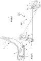
- the rear lever 5 is oriented rearwardly and downwards ( figure 5 ).
- the front lever 10 in both of the two opposite positions obtainable, is oriented rearwardly and upwards ( figure 5 ).
- the front lever 10 in the first position (or advanced position), indicated with ('), is oriented posteriorly and upwards, forming an angle ⁇ of about 80° with respect to a horizontal line.
- the rear lever 5 in the first position (or advanced position), indicated with ('), is oriented rearwards and downwards, forming an angle of about 105° with respect to a horizontal line.
- the second position of the levers 5 and 10 is indicated with (").
- the angle ⁇ formed by the front lever 10 in the first position may be significantly reduced with respect to the prior art.
- the maximum inclination of the front lever 10, in the aforementioned first position may be kept relatively far from reaching inclination values close to 90°. Therefore, the risk that the front lever 10 may be subjected to a situation of instability, as discussed in the introduction, is prevented.
- the configuration illustrated in figures 4 and 5 allows the seat to also perform a tilting movement with considerable variation of the angle of the cushion 2 in a longitudinal vertical plane.
- the backrest 3 also moves rigidly together with the cushion 2.
- the more laid back position corresponds to an elevation at the front of the seat and vice versa
- the less laid back position of the backrest and higher point "H" corresponds to a lowering of the front part of the seat, which also allows adjusting the distance of the most forward part of the seat from the pedals, according to the height of the pilot.
- the two rear levers 5, left and right may be connected to each other by means of a tube or bar or other transversal connecting element 11.
- the transversal connecting element 11 transmits to the right rear lever the adjustment movement imparted to the left rear lever, in this example by a drive 12. It may be appreciated that the transversal connecting element 11 extends outside the seat ( figure 12 ).
- This configuration allows producing a less rigid cushion, since the cushion in this case does not have the task of transmitting the adjustment movement from the (left) drive side to the (right) side without drive. Otherwise, in the absence of a connecting element between the left and right rear levers, the cushion should be structured in such a way as to transmit, without appreciably twisting, the drive movements from the drive side to the opposite side.
- Figures 6 and 7 show a motor drive 12 with a linear actuator 13 connected to the left rear lever 5.
- a linear actuator may be positioned in front of or behind the rear lever and connected to the brackets 6 or 7 or connected to the cushion structure.
- the controls for adjusting the seat may be imparted by different means, for example manually by means of a knob, or by other mechanisms known in the art.
- the front mechanism 4 may comprise a front lever 10 hinged to the front supporting bracket 6 and the lower seat portion 2, whereby on each longitudinal side of the seat a corresponding articulated quadrilateral is formed, consisting of the front and rear 5 levers, the lower seat portion 2 and front 6 and rear supporting brackets 7.
- the articulated quadrilateral allows the seat to be moved by making a point (H) thereof perform a movement between two opposite positions: a first, more advanced and lower position (H', figure 8 ), and a second, more retracted and higher position (H", figure 9 ).
- the front lever 10 has an upper end hinged to the front supporting bracket 6, and a lower end hinged to a front lateral portion of the cushion 2.
- the bracket 6 may be a fixed bracket or a bracket integral with the movable longitudinal guides.
- the front lever 10 is hinged to a front portion of the cushion 2 about a third horizontal hinging axis a3. Moreover, the front lever 10 is also hinged to a respective front supporting bracket 6 about a fourth horizontal hinging axis a4. The third horizontal hinging axis a3 between the front lever 10 and the cushion 2 is located at a lower position than the fourth horizontal hinging axis a4 between the front lever 10 and the relative front supporting bracket 6. Due to this configuration, also the front lever 10 is subject, in use, to a tensile stress and can be advantageously lighter than a lever designed to work on compression, must be sized to work without inflecting due to a peak load.
- the distribution of the forces, in a seat according to the present invention allows reducing the driving load required by the knob or the motor.
- the configuration of the rear lever 5 determines a considerable lever arm respective front supporting bracket 6 in a substantially longitudinal and upward direction, preferably according to an arc with concavity facing downwards.
- the mechanism 4 also comprises a pair of transverse pins 15 which are integral with the cushion and slidingly engaged along the respective slots 14. The configuration may be reversed by making the slots in the seat cushion and the transverse pins in the front supporting brackets 6.
- the distribution of the forces, in a seat according to the present invention allows reducing the driving load required by the knob or the motor.
- the configuration of the rear lever 5 determines a considerable lever arm between the linear action line of the actuator 13 and the hinging axis a2. Consequently, the force needed to lift the cushion or the one-piece seat is much lower.
- This also allows the use of a manual as well as an electric actuator.
- An electric actuator will require reduced power, and may advantageously be small in size, with cost and weight advantages.
- the reduction of the effort required to lift the seat allows eliminating or at least reducing the torsion bar which in traditional systems serves to "aid" the control system to overcome part of the torque generated by the weight of the seated person to be lifted.
- Experimental tests carried out by the Applicant have shown that the driving load may be reduced to less than 50% of that required in traditional systems.
- the system movement speed can also be increased, significantly reducing the drive time to reach the various seat positions.
Landscapes
- Engineering & Computer Science (AREA)
- Aviation & Aerospace Engineering (AREA)
- Transportation (AREA)
- Mechanical Engineering (AREA)
- Seats For Vehicles (AREA)
Claims (7)
- Verstellbarer Sitz für Sportwagen, wobei der Sitz einen unteren Sitzabschnitt (2) mit zwei gegenüberliegenden Längsseiten aufweist, von denen jede versehen ist mit- einer Frontmechanik (4) zum Verbinden eines vorderen Bereichs des unteren Sitzabschnitts (2) mit einer vorderen Stützhalterung (6), und- einem hinteren Hebelarm (5), der an einem hinteren Bereich des unteren Sitzabschnitts (2) gelenkig um eine erste horizontale Schwenkachse (a1) gelagert ist, wobei der hintere Hebelarm (5) des Weiteren an einer entsprechenden hinteren Stützhalterung (7) gelenkig um eine zweite horizontale Schwenkachse (a2) gelagert ist;wobei jede Frontmechanik (4) einen vorderen Hebelarm (10) aufweist, der gelenkig an der vorderen Stützhalterung (6) und dem unteren Sitzabschnitt (2) gelagert ist, wobei an jeder Längsseite des Sitzes ein entsprechendes Gelenkviereck ausgebildet ist, bestehend aus vorderen und hinteren (5) Hebelarmen, dem unteren Sitzabschnitt (2) und vorderen (6) und hinteren Stützhalterungen (7), wobei das Gelenkviereck erlaubt, einen Punkt (H) des Sitzes zwischen zwei unterschiedlichen Positionen zu bewegen: einer ersten, weiter vorragenden und tieferen Position (H') und einer zweiten, zurückliegenderen und höheren Position (H");
dadurch gekennzeichnet, dassim Gebrauch die erste horizontale Schwenkachse (a1) zwischen dem hinteren Hebelarm (5) und dem unteren Sitzabschnitt (2) an einer Position unterhalb der zweiten horizontalen Schwenkachse (a2) angeordnet ist, und zwar zwischen dem hinteren Hebelarm (5) und der hinteren Stützhalterung (7), wodurch jeder hintere Hebelarm (5) auf Zug beansprucht wird, und dassder hintere Hebelarm (5) nach hinten und nach unten gerichtet ist. - Verstellbarer Sitz nach Anspruch 1, wobei der vordere Hebelarm (10) bereitstellt
ein unteres Ende, das an einem vorderen Seitenteil des unteren Sitzabschnitts (2) gelenkig um eine dritte horizontale Schwenkachse (a3) gelagert ist,
ein oberes gelenkiges Ende, das an der vorderen Stützhalterung (6) gelenkig um eine vierte horizontale Schwenkachse (a4) gelagert ist, wobei die dritte horizontale Schwenkachse (a3) in Bezug auf die vierte horizontale Schwenkachse (a4) an einer tieferen Position angeordnet ist. - Verstellbarer Sitz nach Anspruch 1, wobei der vordere Hebelarm (10) bereitstellt
ein unteres Ende, das gelenkig an der vorderen Halterung (6) gelagert ist, und
ein oberes Ende, das gelenkig an einem vorderen Seitenabschnitt des unteren Sitzabschnitts (2) gelagert ist. - Verstellbarer Sitz nach einem der Ansprüche 2 oder 3, wobei der vordere Hebelarm (10) nach hinten und oben gerichtet ist.
- Verstellbarer Sitz nach einem der vorangehenden Ansprüche, wobei die beiden hinteren Hebelarme (5) durch ein transversales Verbindungselement (11) miteinander verbunden sind.
- Verstellbarer Sitz nach Anspruch 5, wobei das transversale Verbindungselement (11) in Form einer Stange oder eines Rohres ist, die bzw. das sich zu dem unteren Sitzabschnitt (2) hin nach außen erstreckt.
- Verstellbarer Sitz nach einem der vorangehenden Ansprüche, aufweisend den unteren Sitzabschnitt (2) und eine Rückenlehne (3), welche Teil einer einzelnen einteiligen Anordnung sind.
Applications Claiming Priority (1)
| Application Number | Priority Date | Filing Date | Title |
|---|---|---|---|
| IT102017000115553A IT201700115553A1 (it) | 2017-10-13 | 2017-10-13 | Sedile regolabile per auto sportive. |
Publications (2)
| Publication Number | Publication Date |
|---|---|
| EP3470261A1 EP3470261A1 (de) | 2019-04-17 |
| EP3470261B1 true EP3470261B1 (de) | 2020-05-13 |
Family
ID=61148434
Family Applications (1)
| Application Number | Title | Priority Date | Filing Date |
|---|---|---|---|
| EP18199523.4A Active EP3470261B1 (de) | 2017-10-13 | 2018-10-10 | Einstellbarer sitz für sportwagen |
Country Status (3)
| Country | Link |
|---|---|
| US (1) | US10933775B2 (de) |
| EP (1) | EP3470261B1 (de) |
| IT (1) | IT201700115553A1 (de) |
Families Citing this family (1)
| Publication number | Priority date | Publication date | Assignee | Title |
|---|---|---|---|---|
| KR20250094979A (ko) * | 2023-12-19 | 2025-06-26 | 현대자동차주식회사 | 차량용 시트 |
Family Cites Families (14)
| Publication number | Priority date | Publication date | Assignee | Title |
|---|---|---|---|---|
| US2809689A (en) * | 1953-12-02 | 1957-10-15 | Gen Motors Corp | Seat adjuster |
| GB854146A (en) * | 1958-05-17 | 1960-11-16 | Evertaut Seating Ltd | Improvements relating to seat assemblies for tractors and like vehicles |
| US3022035A (en) * | 1959-11-02 | 1962-02-20 | Ferro Stamping Co | Seat supporting and adjusting mechanism |
| FR1452002A (fr) * | 1965-01-28 | 1966-02-25 | Simca Automobiles Sa | Siège réglable à dossier basculable vers l'avant notamment pour véhicule automobile |
| FR1453002A (fr) | 1965-11-03 | 1966-04-15 | Wtz Feikeramischen Ind | Dispositif pour la manoeuvre de la commande de la répartition de transmission dans les véhicules automobiles |
| US5437494A (en) * | 1992-10-29 | 1995-08-01 | Life Force Associates, L.P. | Rearward moving seat |
| US5427433A (en) * | 1993-11-17 | 1995-06-27 | Parma Corporation | Rocking, gliding chair and mechanism |
| US5588707A (en) * | 1995-11-14 | 1996-12-31 | General Motors Corporation | Folding seat |
| US6957796B2 (en) * | 2003-01-15 | 2005-10-25 | Lear Corporation | Hydro-formed seat adjuster system |
| JP3860151B2 (ja) * | 2003-08-29 | 2006-12-20 | 株式会社タチエス | 車両用格納式シート |
| DE10354065B4 (de) * | 2003-11-19 | 2006-05-04 | Johnson Controls Gmbh | Fahrzeugsitz, insbesondere für ein Kraftfahrzeug |
| US7201426B2 (en) * | 2004-11-10 | 2007-04-10 | Gm Global Technology Operations, Inc. | Vehicle seating apparatus |
| JP5556553B2 (ja) * | 2010-10-01 | 2014-07-23 | トヨタ車体株式会社 | 車両用シート |
| KR101305815B1 (ko) * | 2011-12-07 | 2013-09-06 | 현대자동차주식회사 | 다목적 차량용 후석 시트의 격납장치 |
-
2017
- 2017-10-13 IT IT102017000115553A patent/IT201700115553A1/it unknown
-
2018
- 2018-10-10 US US16/156,491 patent/US10933775B2/en active Active
- 2018-10-10 EP EP18199523.4A patent/EP3470261B1/de active Active
Non-Patent Citations (1)
| Title |
|---|
| None * |
Also Published As
| Publication number | Publication date |
|---|---|
| US10933775B2 (en) | 2021-03-02 |
| US20190111808A1 (en) | 2019-04-18 |
| EP3470261A1 (de) | 2019-04-17 |
| IT201700115553A1 (it) | 2019-04-13 |
Similar Documents
| Publication | Publication Date | Title |
|---|---|---|
| EP1968814B1 (de) | Zusammenklappbare flachsitzanordnung | |
| EP1924463B1 (de) | Sitzanordnung mit einem sitzpolsterschwenkmechanismus | |
| JP5335698B2 (ja) | 車両座席 | |
| CN111051125B (zh) | 能前摆转的车辆座椅 | |
| US7419218B2 (en) | Rising pivot seat | |
| EP3541655B1 (de) | Sitzeinstellmechanismus | |
| US5697674A (en) | Vehicle seat having a seat proper that is adjustable in height | |
| EP0288439B1 (de) | Vordersitzeinheit für Kraftfahrzeuge, insbesondere für Kraftwagen | |
| EP3134320A1 (de) | Flugzeugsitz mit insassengewichtserfassungsmechanismus zum einstellen der kippneigungskraft | |
| CN110494323B (zh) | 车辆座椅托架、车辆座椅以及车辆 | |
| KR20140007487A (ko) | 차량 시트, 특히 자동차 시트 | |
| US20240262264A1 (en) | Vehicle seat structure and vehicle seat | |
| EP3765331B1 (de) | Sekundärer stabilisierungsschlagbolzen für umklappbare sitze | |
| EP3470261B1 (de) | Einstellbarer sitz für sportwagen | |
| KR101592758B1 (ko) | 차량용 후석 시트 리클라이닝 장치 | |
| EP1945477B1 (de) | Sitzanordnung für zweite reihe mit flachausklappmechanismus mit vorwärtskissenbewegung | |
| US11679697B2 (en) | Device for adjusting a seat position | |
| CN112744132B (zh) | 用于调节座椅位置的设备 | |
| KR102284665B1 (ko) | 자동차의 시트쿠션 경사 조절 장치 | |
| JP6256678B2 (ja) | 車両用シート装置 | |
| US20050269844A1 (en) | Vehicle seat, especially aircraft passenger seat | |
| KR101945797B1 (ko) | 파워 헤드레스팅 장치 | |
| CN111791774A (zh) | 机动车辆座椅 | |
| EP3768551B1 (de) | Zurückziehbare polster für einen reversiblen sitz | |
| EP3972454B1 (de) | Fahrzeugsitz |
Legal Events
| Date | Code | Title | Description |
|---|---|---|---|
| PUAI | Public reference made under article 153(3) epc to a published international application that has entered the european phase |
Free format text: ORIGINAL CODE: 0009012 |
|
| STAA | Information on the status of an ep patent application or granted ep patent |
Free format text: STATUS: THE APPLICATION HAS BEEN PUBLISHED |
|
| AK | Designated contracting states |
Kind code of ref document: A1 Designated state(s): AL AT BE BG CH CY CZ DE DK EE ES FI FR GB GR HR HU IE IS IT LI LT LU LV MC MK MT NL NO PL PT RO RS SE SI SK SM TR |
|
| AX | Request for extension of the european patent |
Extension state: BA ME |
|
| STAA | Information on the status of an ep patent application or granted ep patent |
Free format text: STATUS: REQUEST FOR EXAMINATION WAS MADE |
|
| 17P | Request for examination filed |
Effective date: 20190712 |
|
| RBV | Designated contracting states (corrected) |
Designated state(s): AL AT BE BG CH CY CZ DE DK EE ES FI FR GB GR HR HU IE IS IT LI LT LU LV MC MK MT NL NO PL PT RO RS SE SI SK SM TR |
|
| GRAP | Despatch of communication of intention to grant a patent |
Free format text: ORIGINAL CODE: EPIDOSNIGR1 |
|
| STAA | Information on the status of an ep patent application or granted ep patent |
Free format text: STATUS: GRANT OF PATENT IS INTENDED |
|
| RIN1 | Information on inventor provided before grant (corrected) |
Inventor name: CASTELLI, PIER GUIDO |
|
| INTG | Intention to grant announced |
Effective date: 20191127 |
|
| RAP1 | Party data changed (applicant data changed or rights of an application transferred) |
Owner name: SABELT S.P.A. |
|
| GRAS | Grant fee paid |
Free format text: ORIGINAL CODE: EPIDOSNIGR3 |
|
| GRAA | (expected) grant |
Free format text: ORIGINAL CODE: 0009210 |
|
| STAA | Information on the status of an ep patent application or granted ep patent |
Free format text: STATUS: THE PATENT HAS BEEN GRANTED |
|
| AK | Designated contracting states |
Kind code of ref document: B1 Designated state(s): AL AT BE BG CH CY CZ DE DK EE ES FI FR GB GR HR HU IE IS IT LI LT LU LV MC MK MT NL NO PL PT RO RS SE SI SK SM TR |
|
| REG | Reference to a national code |
Ref country code: GB Ref legal event code: FG4D |
|
| REG | Reference to a national code |
Ref country code: CH Ref legal event code: EP |
|
| REG | Reference to a national code |
Ref country code: DE Ref legal event code: R096 Ref document number: 602018004575 Country of ref document: DE |
|
| REG | Reference to a national code |
Ref country code: AT Ref legal event code: REF Ref document number: 1269831 Country of ref document: AT Kind code of ref document: T Effective date: 20200615 |
|
| REG | Reference to a national code |
Ref country code: LT Ref legal event code: MG4D |
|
| REG | Reference to a national code |
Ref country code: NL Ref legal event code: MP Effective date: 20200513 |
|
| PG25 | Lapsed in a contracting state [announced via postgrant information from national office to epo] |
Ref country code: PT Free format text: LAPSE BECAUSE OF FAILURE TO SUBMIT A TRANSLATION OF THE DESCRIPTION OR TO PAY THE FEE WITHIN THE PRESCRIBED TIME-LIMIT Effective date: 20200914 Ref country code: IS Free format text: LAPSE BECAUSE OF FAILURE TO SUBMIT A TRANSLATION OF THE DESCRIPTION OR TO PAY THE FEE WITHIN THE PRESCRIBED TIME-LIMIT Effective date: 20200913 Ref country code: FI Free format text: LAPSE BECAUSE OF FAILURE TO SUBMIT A TRANSLATION OF THE DESCRIPTION OR TO PAY THE FEE WITHIN THE PRESCRIBED TIME-LIMIT Effective date: 20200513 Ref country code: GR Free format text: LAPSE BECAUSE OF FAILURE TO SUBMIT A TRANSLATION OF THE DESCRIPTION OR TO PAY THE FEE WITHIN THE PRESCRIBED TIME-LIMIT Effective date: 20200814 Ref country code: NO Free format text: LAPSE BECAUSE OF FAILURE TO SUBMIT A TRANSLATION OF THE DESCRIPTION OR TO PAY THE FEE WITHIN THE PRESCRIBED TIME-LIMIT Effective date: 20200813 Ref country code: SE Free format text: LAPSE BECAUSE OF FAILURE TO SUBMIT A TRANSLATION OF THE DESCRIPTION OR TO PAY THE FEE WITHIN THE PRESCRIBED TIME-LIMIT Effective date: 20200513 Ref country code: LT Free format text: LAPSE BECAUSE OF FAILURE TO SUBMIT A TRANSLATION OF THE DESCRIPTION OR TO PAY THE FEE WITHIN THE PRESCRIBED TIME-LIMIT Effective date: 20200513 |
|
| PG25 | Lapsed in a contracting state [announced via postgrant information from national office to epo] |
Ref country code: BG Free format text: LAPSE BECAUSE OF FAILURE TO SUBMIT A TRANSLATION OF THE DESCRIPTION OR TO PAY THE FEE WITHIN THE PRESCRIBED TIME-LIMIT Effective date: 20200813 Ref country code: HR Free format text: LAPSE BECAUSE OF FAILURE TO SUBMIT A TRANSLATION OF THE DESCRIPTION OR TO PAY THE FEE WITHIN THE PRESCRIBED TIME-LIMIT Effective date: 20200513 Ref country code: LV Free format text: LAPSE BECAUSE OF FAILURE TO SUBMIT A TRANSLATION OF THE DESCRIPTION OR TO PAY THE FEE WITHIN THE PRESCRIBED TIME-LIMIT Effective date: 20200513 Ref country code: RS Free format text: LAPSE BECAUSE OF FAILURE TO SUBMIT A TRANSLATION OF THE DESCRIPTION OR TO PAY THE FEE WITHIN THE PRESCRIBED TIME-LIMIT Effective date: 20200513 |
|
| REG | Reference to a national code |
Ref country code: AT Ref legal event code: MK05 Ref document number: 1269831 Country of ref document: AT Kind code of ref document: T Effective date: 20200513 |
|
| PG25 | Lapsed in a contracting state [announced via postgrant information from national office to epo] |
Ref country code: AL Free format text: LAPSE BECAUSE OF FAILURE TO SUBMIT A TRANSLATION OF THE DESCRIPTION OR TO PAY THE FEE WITHIN THE PRESCRIBED TIME-LIMIT Effective date: 20200513 Ref country code: NL Free format text: LAPSE BECAUSE OF FAILURE TO SUBMIT A TRANSLATION OF THE DESCRIPTION OR TO PAY THE FEE WITHIN THE PRESCRIBED TIME-LIMIT Effective date: 20200513 |
|
| PG25 | Lapsed in a contracting state [announced via postgrant information from national office to epo] |
Ref country code: DK Free format text: LAPSE BECAUSE OF FAILURE TO SUBMIT A TRANSLATION OF THE DESCRIPTION OR TO PAY THE FEE WITHIN THE PRESCRIBED TIME-LIMIT Effective date: 20200513 Ref country code: AT Free format text: LAPSE BECAUSE OF FAILURE TO SUBMIT A TRANSLATION OF THE DESCRIPTION OR TO PAY THE FEE WITHIN THE PRESCRIBED TIME-LIMIT Effective date: 20200513 Ref country code: CZ Free format text: LAPSE BECAUSE OF FAILURE TO SUBMIT A TRANSLATION OF THE DESCRIPTION OR TO PAY THE FEE WITHIN THE PRESCRIBED TIME-LIMIT Effective date: 20200513 Ref country code: IT Free format text: LAPSE BECAUSE OF FAILURE TO SUBMIT A TRANSLATION OF THE DESCRIPTION OR TO PAY THE FEE WITHIN THE PRESCRIBED TIME-LIMIT Effective date: 20200513 Ref country code: ES Free format text: LAPSE BECAUSE OF FAILURE TO SUBMIT A TRANSLATION OF THE DESCRIPTION OR TO PAY THE FEE WITHIN THE PRESCRIBED TIME-LIMIT Effective date: 20200513 Ref country code: SM Free format text: LAPSE BECAUSE OF FAILURE TO SUBMIT A TRANSLATION OF THE DESCRIPTION OR TO PAY THE FEE WITHIN THE PRESCRIBED TIME-LIMIT Effective date: 20200513 Ref country code: RO Free format text: LAPSE BECAUSE OF FAILURE TO SUBMIT A TRANSLATION OF THE DESCRIPTION OR TO PAY THE FEE WITHIN THE PRESCRIBED TIME-LIMIT Effective date: 20200513 Ref country code: EE Free format text: LAPSE BECAUSE OF FAILURE TO SUBMIT A TRANSLATION OF THE DESCRIPTION OR TO PAY THE FEE WITHIN THE PRESCRIBED TIME-LIMIT Effective date: 20200513 |
|
| REG | Reference to a national code |
Ref country code: DE Ref legal event code: R097 Ref document number: 602018004575 Country of ref document: DE |
|
| PG25 | Lapsed in a contracting state [announced via postgrant information from national office to epo] |
Ref country code: PL Free format text: LAPSE BECAUSE OF FAILURE TO SUBMIT A TRANSLATION OF THE DESCRIPTION OR TO PAY THE FEE WITHIN THE PRESCRIBED TIME-LIMIT Effective date: 20200513 Ref country code: SK Free format text: LAPSE BECAUSE OF FAILURE TO SUBMIT A TRANSLATION OF THE DESCRIPTION OR TO PAY THE FEE WITHIN THE PRESCRIBED TIME-LIMIT Effective date: 20200513 |
|
| PLBE | No opposition filed within time limit |
Free format text: ORIGINAL CODE: 0009261 |
|
| STAA | Information on the status of an ep patent application or granted ep patent |
Free format text: STATUS: NO OPPOSITION FILED WITHIN TIME LIMIT |
|
| 26N | No opposition filed |
Effective date: 20210216 |
|
| PG25 | Lapsed in a contracting state [announced via postgrant information from national office to epo] |
Ref country code: SI Free format text: LAPSE BECAUSE OF FAILURE TO SUBMIT A TRANSLATION OF THE DESCRIPTION OR TO PAY THE FEE WITHIN THE PRESCRIBED TIME-LIMIT Effective date: 20200513 |
|
| PG25 | Lapsed in a contracting state [announced via postgrant information from national office to epo] |
Ref country code: MC Free format text: LAPSE BECAUSE OF FAILURE TO SUBMIT A TRANSLATION OF THE DESCRIPTION OR TO PAY THE FEE WITHIN THE PRESCRIBED TIME-LIMIT Effective date: 20200513 Ref country code: LU Free format text: LAPSE BECAUSE OF NON-PAYMENT OF DUE FEES Effective date: 20201010 |
|
| REG | Reference to a national code |
Ref country code: BE Ref legal event code: MM Effective date: 20201031 |
|
| PG25 | Lapsed in a contracting state [announced via postgrant information from national office to epo] |
Ref country code: BE Free format text: LAPSE BECAUSE OF NON-PAYMENT OF DUE FEES Effective date: 20201031 |
|
| PG25 | Lapsed in a contracting state [announced via postgrant information from national office to epo] |
Ref country code: IE Free format text: LAPSE BECAUSE OF NON-PAYMENT OF DUE FEES Effective date: 20201010 |
|
| REG | Reference to a national code |
Ref country code: CH Ref legal event code: PL |
|
| PG25 | Lapsed in a contracting state [announced via postgrant information from national office to epo] |
Ref country code: TR Free format text: LAPSE BECAUSE OF FAILURE TO SUBMIT A TRANSLATION OF THE DESCRIPTION OR TO PAY THE FEE WITHIN THE PRESCRIBED TIME-LIMIT Effective date: 20200513 Ref country code: MT Free format text: LAPSE BECAUSE OF FAILURE TO SUBMIT A TRANSLATION OF THE DESCRIPTION OR TO PAY THE FEE WITHIN THE PRESCRIBED TIME-LIMIT Effective date: 20200513 Ref country code: CY Free format text: LAPSE BECAUSE OF FAILURE TO SUBMIT A TRANSLATION OF THE DESCRIPTION OR TO PAY THE FEE WITHIN THE PRESCRIBED TIME-LIMIT Effective date: 20200513 |
|
| PG25 | Lapsed in a contracting state [announced via postgrant information from national office to epo] |
Ref country code: MK Free format text: LAPSE BECAUSE OF FAILURE TO SUBMIT A TRANSLATION OF THE DESCRIPTION OR TO PAY THE FEE WITHIN THE PRESCRIBED TIME-LIMIT Effective date: 20200513 |
|
| PG25 | Lapsed in a contracting state [announced via postgrant information from national office to epo] |
Ref country code: LI Free format text: LAPSE BECAUSE OF NON-PAYMENT OF DUE FEES Effective date: 20211031 Ref country code: CH Free format text: LAPSE BECAUSE OF NON-PAYMENT OF DUE FEES Effective date: 20211031 |
|
| PGFP | Annual fee paid to national office [announced via postgrant information from national office to epo] |
Ref country code: FR Payment date: 20250930 Year of fee payment: 8 |
|
| PGFP | Annual fee paid to national office [announced via postgrant information from national office to epo] |
Ref country code: DE Payment date: 20251027 Year of fee payment: 8 |
|
| PGFP | Annual fee paid to national office [announced via postgrant information from national office to epo] |
Ref country code: GB Payment date: 20251022 Year of fee payment: 8 |