EP3469936B1 - Heating device and smoking set having same - Google Patents
Heating device and smoking set having same Download PDFInfo
- Publication number
- EP3469936B1 EP3469936B1 EP19154281.0A EP19154281A EP3469936B1 EP 3469936 B1 EP3469936 B1 EP 3469936B1 EP 19154281 A EP19154281 A EP 19154281A EP 3469936 B1 EP3469936 B1 EP 3469936B1
- Authority
- EP
- European Patent Office
- Prior art keywords
- heating
- heating element
- tobacco cigarette
- chamber
- heating device
- Prior art date
- Legal status (The legal status is an assumption and is not a legal conclusion. Google has not performed a legal analysis and makes no representation as to the accuracy of the status listed.)
- Active
Links
- 238000010438 heat treatment Methods 0.000 title claims description 233
- 230000000391 smoking effect Effects 0.000 title claims description 21
- 241000208125 Nicotiana Species 0.000 claims description 86
- 235000002637 Nicotiana tabacum Nutrition 0.000 claims description 86
- 235000019504 cigarettes Nutrition 0.000 claims description 85
- 230000005674 electromagnetic induction Effects 0.000 claims description 33
- 230000001939 inductive effect Effects 0.000 claims description 17
- 239000000758 substrate Substances 0.000 claims description 6
- 239000003571 electronic cigarette Substances 0.000 description 10
- 230000004907 flux Effects 0.000 description 8
- 238000000034 method Methods 0.000 description 7
- 238000007599 discharging Methods 0.000 description 6
- 239000004020 conductor Substances 0.000 description 4
- 230000000694 effects Effects 0.000 description 4
- 239000011269 tar Substances 0.000 description 4
- 230000005611 electricity Effects 0.000 description 3
- 230000036541 health Effects 0.000 description 3
- XEEYBQQBJWHFJM-UHFFFAOYSA-N Iron Chemical compound [Fe] XEEYBQQBJWHFJM-UHFFFAOYSA-N 0.000 description 2
- 239000004642 Polyimide Substances 0.000 description 2
- 239000000443 aerosol Substances 0.000 description 2
- 239000000969 carrier Substances 0.000 description 2
- 230000006698 induction Effects 0.000 description 2
- 239000011810 insulating material Substances 0.000 description 2
- UGKDIUIOSMUOAW-UHFFFAOYSA-N iron nickel Chemical compound [Fe].[Ni] UGKDIUIOSMUOAW-UHFFFAOYSA-N 0.000 description 2
- 239000000463 material Substances 0.000 description 2
- 229920001721 polyimide Polymers 0.000 description 2
- 239000000843 powder Substances 0.000 description 2
- 229910000702 sendust Inorganic materials 0.000 description 2
- 239000000126 substance Substances 0.000 description 2
- 239000005995 Aluminium silicate Substances 0.000 description 1
- UGFAIRIUMAVXCW-UHFFFAOYSA-N Carbon monoxide Chemical compound [O+]#[C-] UGFAIRIUMAVXCW-UHFFFAOYSA-N 0.000 description 1
- RYGMFSIKBFXOCR-UHFFFAOYSA-N Copper Chemical compound [Cu] RYGMFSIKBFXOCR-UHFFFAOYSA-N 0.000 description 1
- -1 UP-4250 Polymers 0.000 description 1
- 239000000654 additive Substances 0.000 description 1
- 230000000996 additive effect Effects 0.000 description 1
- 239000004964 aerogel Substances 0.000 description 1
- 229910052782 aluminium Inorganic materials 0.000 description 1
- XAGFODPZIPBFFR-UHFFFAOYSA-N aluminium Chemical compound [Al] XAGFODPZIPBFFR-UHFFFAOYSA-N 0.000 description 1
- 235000012211 aluminium silicate Nutrition 0.000 description 1
- PZZYQPZGQPZBDN-UHFFFAOYSA-N aluminium silicate Chemical compound O=[Al]O[Si](=O)O[Al]=O PZZYQPZGQPZBDN-UHFFFAOYSA-N 0.000 description 1
- 229910000323 aluminium silicate Inorganic materials 0.000 description 1
- 239000010425 asbestos Substances 0.000 description 1
- 238000000889 atomisation Methods 0.000 description 1
- 235000012215 calcium aluminium silicate Nutrition 0.000 description 1
- 239000000378 calcium silicate Substances 0.000 description 1
- 229910052918 calcium silicate Inorganic materials 0.000 description 1
- OYACROKNLOSFPA-UHFFFAOYSA-N calcium;dioxido(oxo)silane Chemical compound [Ca+2].[O-][Si]([O-])=O OYACROKNLOSFPA-UHFFFAOYSA-N 0.000 description 1
- 229910002091 carbon monoxide Inorganic materials 0.000 description 1
- 231100000357 carcinogen Toxicity 0.000 description 1
- 239000003183 carcinogenic agent Substances 0.000 description 1
- 238000005266 casting Methods 0.000 description 1
- 230000008859 change Effects 0.000 description 1
- 239000012141 concentrate Substances 0.000 description 1
- 229910052802 copper Inorganic materials 0.000 description 1
- 239000010949 copper Substances 0.000 description 1
- 230000003247 decreasing effect Effects 0.000 description 1
- 230000001419 dependent effect Effects 0.000 description 1
- 230000001627 detrimental effect Effects 0.000 description 1
- 238000010586 diagram Methods 0.000 description 1
- 238000005516 engineering process Methods 0.000 description 1
- 239000003822 epoxy resin Substances 0.000 description 1
- 239000000796 flavoring agent Substances 0.000 description 1
- 235000019634 flavors Nutrition 0.000 description 1
- 239000003292 glue Substances 0.000 description 1
- LNEPOXFFQSENCJ-UHFFFAOYSA-N haloperidol Chemical compound C1CC(O)(C=2C=CC(Cl)=CC=2)CCN1CCCC(=O)C1=CC=C(F)C=C1 LNEPOXFFQSENCJ-UHFFFAOYSA-N 0.000 description 1
- 238000009413 insulation Methods 0.000 description 1
- 230000001788 irregular Effects 0.000 description 1
- 239000000696 magnetic material Substances 0.000 description 1
- 230000035699 permeability Effects 0.000 description 1
- 229920001568 phenolic resin Polymers 0.000 description 1
- 239000005011 phenolic resin Substances 0.000 description 1
- 239000004033 plastic Substances 0.000 description 1
- 229920000647 polyepoxide Polymers 0.000 description 1
- 238000004321 preservation Methods 0.000 description 1
- 230000008569 process Effects 0.000 description 1
- 229920005989 resin Polymers 0.000 description 1
- 239000011347 resin Substances 0.000 description 1
- 229910052895 riebeckite Inorganic materials 0.000 description 1
- 239000000779 smoke Substances 0.000 description 1
- 229920003002 synthetic resin Polymers 0.000 description 1
- 239000000057 synthetic resin Substances 0.000 description 1
- 239000002341 toxic gas Substances 0.000 description 1
- 230000009466 transformation Effects 0.000 description 1
- 230000001131 transforming effect Effects 0.000 description 1
Images


Classifications
-
- A—HUMAN NECESSITIES
- A24—TOBACCO; CIGARS; CIGARETTES; SIMULATED SMOKING DEVICES; SMOKERS' REQUISITES
- A24F—SMOKERS' REQUISITES; MATCH BOXES; SIMULATED SMOKING DEVICES
- A24F40/00—Electrically operated smoking devices; Component parts thereof; Manufacture thereof; Maintenance or testing thereof; Charging means specially adapted therefor
- A24F40/40—Constructional details, e.g. connection of cartridges and battery parts
- A24F40/46—Shape or structure of electric heating means
- A24F40/465—Shape or structure of electric heating means specially adapted for induction heating
-
- A—HUMAN NECESSITIES
- A24—TOBACCO; CIGARS; CIGARETTES; SIMULATED SMOKING DEVICES; SMOKERS' REQUISITES
- A24F—SMOKERS' REQUISITES; MATCH BOXES; SIMULATED SMOKING DEVICES
- A24F40/00—Electrically operated smoking devices; Component parts thereof; Manufacture thereof; Maintenance or testing thereof; Charging means specially adapted therefor
- A24F40/50—Control or monitoring
- A24F40/51—Arrangement of sensors
-
- A—HUMAN NECESSITIES
- A24—TOBACCO; CIGARS; CIGARETTES; SIMULATED SMOKING DEVICES; SMOKERS' REQUISITES
- A24F—SMOKERS' REQUISITES; MATCH BOXES; SIMULATED SMOKING DEVICES
- A24F40/00—Electrically operated smoking devices; Component parts thereof; Manufacture thereof; Maintenance or testing thereof; Charging means specially adapted therefor
- A24F40/50—Control or monitoring
- A24F40/57—Temperature control
-
- H—ELECTRICITY
- H05—ELECTRIC TECHNIQUES NOT OTHERWISE PROVIDED FOR
- H05B—ELECTRIC HEATING; ELECTRIC LIGHT SOURCES NOT OTHERWISE PROVIDED FOR; CIRCUIT ARRANGEMENTS FOR ELECTRIC LIGHT SOURCES, IN GENERAL
- H05B3/00—Ohmic-resistance heating
- H05B3/20—Heating elements having extended surface area substantially in a two-dimensional plane, e.g. plate-heater
- H05B3/22—Heating elements having extended surface area substantially in a two-dimensional plane, e.g. plate-heater non-flexible
- H05B3/26—Heating elements having extended surface area substantially in a two-dimensional plane, e.g. plate-heater non-flexible heating conductor mounted on insulating base
-
- H—ELECTRICITY
- H05—ELECTRIC TECHNIQUES NOT OTHERWISE PROVIDED FOR
- H05B—ELECTRIC HEATING; ELECTRIC LIGHT SOURCES NOT OTHERWISE PROVIDED FOR; CIRCUIT ARRANGEMENTS FOR ELECTRIC LIGHT SOURCES, IN GENERAL
- H05B3/00—Ohmic-resistance heating
- H05B3/40—Heating elements having the shape of rods or tubes
- H05B3/42—Heating elements having the shape of rods or tubes non-flexible
-
- H—ELECTRICITY
- H05—ELECTRIC TECHNIQUES NOT OTHERWISE PROVIDED FOR
- H05B—ELECTRIC HEATING; ELECTRIC LIGHT SOURCES NOT OTHERWISE PROVIDED FOR; CIRCUIT ARRANGEMENTS FOR ELECTRIC LIGHT SOURCES, IN GENERAL
- H05B6/00—Heating by electric, magnetic or electromagnetic fields
- H05B6/02—Induction heating
- H05B6/10—Induction heating apparatus, other than furnaces, for specific applications
- H05B6/105—Induction heating apparatus, other than furnaces, for specific applications using a susceptor
-
- H—ELECTRICITY
- H05—ELECTRIC TECHNIQUES NOT OTHERWISE PROVIDED FOR
- H05B—ELECTRIC HEATING; ELECTRIC LIGHT SOURCES NOT OTHERWISE PROVIDED FOR; CIRCUIT ARRANGEMENTS FOR ELECTRIC LIGHT SOURCES, IN GENERAL
- H05B6/00—Heating by electric, magnetic or electromagnetic fields
- H05B6/02—Induction heating
- H05B6/36—Coil arrangements
-
- A—HUMAN NECESSITIES
- A24—TOBACCO; CIGARS; CIGARETTES; SIMULATED SMOKING DEVICES; SMOKERS' REQUISITES
- A24F—SMOKERS' REQUISITES; MATCH BOXES; SIMULATED SMOKING DEVICES
- A24F40/00—Electrically operated smoking devices; Component parts thereof; Manufacture thereof; Maintenance or testing thereof; Charging means specially adapted therefor
- A24F40/20—Devices using solid inhalable precursors
-
- A—HUMAN NECESSITIES
- A61—MEDICAL OR VETERINARY SCIENCE; HYGIENE
- A61M—DEVICES FOR INTRODUCING MEDIA INTO, OR ONTO, THE BODY; DEVICES FOR TRANSDUCING BODY MEDIA OR FOR TAKING MEDIA FROM THE BODY; DEVICES FOR PRODUCING OR ENDING SLEEP OR STUPOR
- A61M15/00—Inhalators
- A61M15/06—Inhaling appliances shaped like cigars, cigarettes or pipes
-
- H—ELECTRICITY
- H05—ELECTRIC TECHNIQUES NOT OTHERWISE PROVIDED FOR
- H05B—ELECTRIC HEATING; ELECTRIC LIGHT SOURCES NOT OTHERWISE PROVIDED FOR; CIRCUIT ARRANGEMENTS FOR ELECTRIC LIGHT SOURCES, IN GENERAL
- H05B6/00—Heating by electric, magnetic or electromagnetic fields
- H05B6/02—Induction heating
- H05B6/04—Sources of current
-
- H—ELECTRICITY
- H05—ELECTRIC TECHNIQUES NOT OTHERWISE PROVIDED FOR
- H05B—ELECTRIC HEATING; ELECTRIC LIGHT SOURCES NOT OTHERWISE PROVIDED FOR; CIRCUIT ARRANGEMENTS FOR ELECTRIC LIGHT SOURCES, IN GENERAL
- H05B6/00—Heating by electric, magnetic or electromagnetic fields
- H05B6/02—Induction heating
- H05B6/10—Induction heating apparatus, other than furnaces, for specific applications
- H05B6/105—Induction heating apparatus, other than furnaces, for specific applications using a susceptor
- H05B6/108—Induction heating apparatus, other than furnaces, for specific applications using a susceptor for heating a fluid
Definitions
- the present disclosure relates to the field of smoking sets, and particularly to a heating device and a smoking set having same.
- the tobacco cigarette as an additive is adored by lots of people.
- tars and carbon monoxide etc. are harmful to people's health.
- tens of substances in the tar are carcinogens, which enormous affect people's health.
- many countries are gradually prohibiting smoking tobacco cigarettes in the public.
- the electronic cigarette heats the tobacco cigarette or cartridge for atomization, so as to generate an aerosol. Since the electronic cigarette has similar flavor and appearance with the real tobacco cigarette, ridding the harmful substances such as tars and particulate matters in the tobacco cigarette, the electronic cigarette become more and more popular among the users.
- the central heating as described supra would cause heating unevenly, that is, inside the tobacco cigarette has high temperature whereas outside the tobacco cigarette has low temperature, which tremendously affect taste of the electronic cigarette; however, the around heating as described supra generally generates a closed annulus, but the annulus-shaped metallic heating element would concentrate the electromagnetic inductive lines on the closed annulus itself, which may cause magnetic shielding to the tobacco cigarette disposed at a central of the closed annulus, so that the tobacco cigarette absorbing and transforming the magnetic flux would be affected, with consequently low heating efficiency and uneven heating to the tobacco cigarette to damage taste of the electronic cigarette.
- Document WO2013098395 discloses a heating device of the prior art.
- the present disclosure relates to a heating device and a smoking set having the same, which are capable of improving efficiency of central heating with evenly heating, such that the electronic cigarette has a good taste.
- the heating device includes a base; a supporter disposed on the base, the supporter has a chamber therein; the chamber being configured for receiving the tobacco cigarette; an electromagnetic induction coil, wound around the supporter and configured for generating an alternative magnetic field in the chamber; at least one first heating element, disposed in the chamber, when the tobacco cigarette is disposed in the chamber, the at least one first heating element contacts an outer surface of the tobacco cigarette and configured for generating a vortex in the alternative magnetic field to heat the tobacco cigarette; and
- the at least one first heating element includes two first heating elements, and the two first heating elements are spaced from each other by a predetermined distance along a circumferential direction of an inner wall of the chamber, thus forming the cut.
- the two first heating elements include a first arc-shaped heating piece and a second arc-shaped heating piece matched with the outer surface of the tobacco cigarette, and the first arc-shaped heating piece and the second arc-shaped heating piece are symmetrically disposed at two sides of the second heating element.
- the second heating element is a plate-shaped structure with a first surface and a second surface, the first surface has a larger area than the second surface, the first surface faces the cut.
- the first surface is perpendicular with a line connecting two ends of the first arc-shaped heating piece, and the first surface is perpendicular with a line connecting two ends of the second arc-shaped heating piece;
- the second surface is parallel with a line connecting two ends of the first arc-shaped heating piece, and the second surface is parallel with a line connecting two ends of the second arc-shaped heating piece.
- the heating device further includes a heat insulating layer, the heat insulating layer is disposed between the electromagnetic inductive coil and the at least one first heating element, the heat insulating layer is configured to reduce heat in the chamber transferring outside.
- the base includes a bulge part and a substrate, the bulge part is inserted into the chamber of the supporter to allow the supporter to be installed in the base.
- the base includes a fixing structure, configured to fix the second heating element in the base.
- the heating device further includes a temperature sensor, the temperature sensor is disposed on the second heating element or the at least one first heating element, or between the at least one first heating element and the second heating element.
- the present disclosure further provides an electronic smoking set having the heating device as described supra and a power supply module; the power supply module is coupled with the electromagnetic inductive coil in the heating device and configured for supplying an alternating current to the electromagnetic inductive coil.
- the present disclosure relates to a heating device and a smoking set having same; when the first heating element heats the tobacco cigarette from outside to inside, while the second heating element heats the tobacco cigarette from inside to outside, therefore heating the tobacco cigarette evenly.
- the first heating element has at least one cut extending along an axial direction of the electromagnetic inductive coil, the cut may ensure the second heating element to absorb sufficient electromagnetic flux, so as to improve the heating efficiency of the second heating element as well as improve the heating efficiency for heating the tobacco cigarette, therefore ensuring the tobacco cigarette to be heated evenly, making the taste of the tobacco cigarette consistent during smoking, improving the taste of the electronic smoking set and improving user experience.
- the electronic smoking set 300 includes a heating device 100, a power supply module 110 and a tobacco cigarette 200.
- the power supply module 110 is coupled with the electromagnetic inductive coil 50 in the heating device 100 and configured for supplying an alternating current to the electromagnetic inductive coil 50.
- the heating device 100 is configured to heat the tobacco cigarette 200.
- the tobacco cigarette 200 may be one or more tobacco shaped in rods.
- the tobacco cigarette 200 is disposed inside the heating device 100. More specifically, the heating device 100 has a chamber 201 therein configured for receiving the tobacco cigarette 200.
- the heating device 100 is configured to heat the tobacco cigarette 200, making the tobacco cigarette 200 to generate an aerosol drawn directly in combusting and non-burning methods, that is, the tobacco cigarette 200 doesn't need to be burnt to generate tar etc. some toxic gas, therefore decreasing the detrimental on the smokers' health.
- the heating device 100 will be described in detail hereinafter in accordance with embodiments of the present disclosure.
- the heating device 100 includes a base 10, a supporter 20, at least one first heating element 30, a second heating element 40 and an electromagnetic induction coil 50.
- the supporter 20 is installed on the base 10.
- the supporter 20 has a chamber 201 therein configured for receiving the tobacco cigarette 200.
- the electromagnetic induction coil 50 is wound around the supporter 20 and configured for generating an alternative magnetic field in the chamber 201, such that the at least one first heating element 30 and second heating element 40 generate vortexes respectively.
- the at least one first heating element 30 is disposed in the chamber 201, when the tobacco cigarette 200 is received in the chamber 201, the at least one first heating element 30 contacts an outer surface of the tobacco cigarette 200 and generates a vortex in the alternative magnetic field to heat the tobacco cigarette 200, that means, heating outside the tobacco cigarette 200 directly. Moreover, the at least one first heating element 30 is disposed around a periphery of the second heating element 40 to form a cut 304 extending along an axial direction of the induction coil 50, which may ensure sufficient usage of the electromagnetic flux without influencing the second heating element 40 to absorb and transform the electromagnetic flux.
- the electromagnetic inductive lines in the chamber 201 passing through the chamber 201 are parallel with the axial direction of the induction coil 50.
- the second heating element 40 is installed on the base 10, when the tobacco cigarette 200 is received inside the chamber 201, the second heating element 40 is inserted into the tobacco cigarette 200 and generates a vertex to heat the tobacco cigarette 200, that means, heating the tobacco cigarette 200 inside directly thus to heat the tobacco cigarette 200 from inside to outside, with while the at least one first heating element 30 is heating the tobacco cigarette 200 from outside to inside, therefore the tobacco cigarette 200 is heated evenly.
- the first heating element 30 has a cut 304 for ensuring the second heating element 40 to absorb sufficient electromagnetic flux, such that improving the heating efficiency of the second heating element 40 heating the tobacco cigarette 200, further, making sure the tobacco cigarette 200 is heated evenly so a taste of the electronic cigarette 300 is improved.
- the base 10 includes a bulge part 101 and a substrate 102, the bulge part 101 is integral with the substrate 102. More specifically, the bulge part 101 and the substrate 102 are integral as a whole by casting or stamping technologies etc. no limitation herein. In some embodiments, the bulge part 101 may be detachably connected with the substrate 102. As used herein, the bulge part 101 is roughly a cylindrical structure; the bulge part 101 is inserted into the chamber 201 of the supporter 20 to install the supporter 20 on the base 10.
- the base 10 has a fastening structure 103 for fixing the second heating element 40 on the base 10.
- the bulge part 101 has the fastening structure 103, and the fastening structure 103 is a groove, one end of the second heating element 40 is inserted into the groove, so the second heating element 40 is fixed on the base 10.
- the second heating element 40 may be fixed on the base 10 via other methods, such as screw threads etc.
- the supporter 20 is roughly a hollow cylinder, an inner diameter of the supporter 20 is roughly larger than an outer diameter of the bulge part 101, so the bulge part 101 is inserted into the supporter 20, and the supporter 20 is installed in the base 10. Since the supporter 20 is hollow, the supporter 20 has a chamber 201 therein for receiving the tobacco cigarette 200. More specifically, part of the tobacco cigarette 200 is received into the chamber 201, remaining part of the tobacco cigarette 200 protrudes outside the chamber 201.
- the at least one first heating element 30 is disposed in the chamber 201, more specifically, the inner wall of the supporter 20 has a slot 202 for engaging with the first heating element 30 that is installable on the base 20, so the at least one first heating element 30 is disposed in the chamber 201.
- the at least one first heating element 30 is disposed between the tobacco cigarette 200 and the supporter 20, and the at least one first heating element 30 contacts the outer surface of the tobacco cigarette 200 and generates a vertex in the magnetic field to heat the tobacco cigarette 200, that means, the tobacco cigarette 200 is heated from outside to inside, which is the first direction as shown in FIG. 6 .
- the electromagnetic heating method is adopted to heat the tobacco cigarette 200, therefore, the at least one first heating element 30 is made by a metallic conductor, electromagnetic materials are preferred to bring a better effect of electromagnetic heating.
- the at least one first heating element 30 is made of at least one or more selected from a group of iron powder, iron-nickel 50, sendust cores and MPP molypermalloy powder etc.
- the at least one first heating element 30 has a cut 304 thereon extending along an axial direction of the electromagnetic induction coil 50. More specifically, the at least one first heating element 30 includes two first heating element, and two first heating elements are spaced from each other by a predetermined distance along a circumferential direction of an inner wall of the chamber, thus forming the cut 304. Since the electromagnetic induction coil 50 is provided in the embodiments of the present disclosure, the tobacco cigarette 200 is heated via the electromagnetic heating method. Therefore, to utilize the electromagnetic flux sufficiently and not to affect the second heating element 40 absorbing the electromagnetic flux, at least one first heating element 30 is needed to be wound around a periphery of the tobacco cigarette 200, forming the cut 304.
- two first heating elements are disposed along the circumferential direction of the inner wall of the chamber 201, thus forming the cut 304, rather than a closed loop.
- the number of the cuts 304 may be multiple, such as one, two, three or four etc. no limitation to the number of the cuts 304 herein.
- two first heating elements include a first arc-shaped heating piece 301 and a second arc-shaped heating piece 302 matched with the outer surface of the tobacco cigarette 200.
- the first arc-shaped heating piece 301 and a second arc-shaped heating piece 302 are disposed symmetrically at two sides of the second heating element 40, thus forming the cut 304 that ensures the second heating element 40 to absorb electromagnetic inductive lines for transformation, two first heating elements 30 symmetrically set at two sides of the second heating element 40 may make the tobacco cigarette 200 available for heating evenly.
- the two first heating elements may be integrated as a whole. More specifically, the two first heating elements may be a sleeve, the side wall of the sleeve is provided with two or more than two grooves extending along the axial direction of the sleeve, thus forming the cut 304.
- the second heating element 40 is installed on the base 10; more specifically, one end of the second heating element 40 is inserted into the groove to fix the second heating element 40 on the base 10.
- the second heating element 40 is inserted into the tobacco cigarette 200 and generates a vertex in the alternating magnetic field to heat the tobacco cigarette 200, therefore the tobacco cigarette 200 is heated from inside to outside, which is the second direction as shown in FIG. 6 .
- the material of the second heating element 40 is similar with the at least one first heating element 30, that is the second heating element 40 is made by metallic conductor, permeability magnetic material is preferred which has better effect of electromagnetic inductive heating.
- the second heating element 40 is made of at least one or more selected from a group of iron powder, iron-nickel 50, sendust cores and MPP molypermalloy powder etc.
- the second heating element 40 is a laminated structure with a first surface 401 and a second surface 402.
- an area of the first surface 401 is larger than that of the second surface 402, the first surface 401 faces the cut 304. More specifically, the first surface 401 is perpendicular with a line connecting with two ends of the first arc-shaped heating piece 301, and the first surface 401 is perpendicular with a line connecting with two ends of the second arc-shaped heating piece 302, and the second surface 402 is parallel with a line connecting with two ends of the first arc-shaped heating piece 301, and the second surface 402 is parallel with a line connecting with two ends of the second arc-shaped heating piece 302.
- the second heating element 40 is plate-shaped structure, the area of the first surface 401 is larger than that of the second surface 402, therefore, the second heating element 40 generates more heat on the first surface 401 than the second surface 402. Meanwhile, since between the first arc-shaped heating element 301 and the second arc-shaped heating element 302 has a cut 304, enabling temperature of the area near to the first arc-shaped heating element 301 and the second arc-shaped heating element 302 is higher than the temperature of the area near to the cut 304.
- the tobacco cigarette 200 is further heated evenly, so as to improve the taste of the electronic smoking set 300.
- the electromagnetic induction coil 50 is wound around the supporter 20; more specifically, the supporter 20 has a first position stop 205 and a second position stop 206.
- the electromagnetic induction coil 50 is wound around the supporter 20 between the first and second position stops 205, 206.
- the electromagnetic induction coil 50 is used to generate a changing magnetic field, such that the at least first heating element 30 and the second heating element 40 generate vortexes.
- the electromagnetic induction coil 50 when an alternating current is passing through the electromagnetic induction coil 50, such as the fast changing high-frequency and high-voltage current passes through the electromagnetic induction coil 50, it would generate fast changing alternative magnetic field, the at least one first heating element 30 and the second heating element 40 are disposed in the alternative magnetic field to do cutting motion for cutting alternative magnetic field lines to generate alternating current, that is the vortex.
- the vortex makes carriers of the at least first heating element 50 and the second heating element 40 do high-speed and irregular motion, the carriers are crashing into one another and rubbing with one another to generate heat energy, so as to heat the tobacco cigarette 200.
- the electromagnetic induction coil 50 may be made by electricity conductive materials, such as, the electromagnetic induction coil 50 may be made by good electricity conductor with cheap price such as copper wires and aluminum filaments etc.
- two electromagnetic induction coils 50 are provided, including a first coil (not shown) and a second coil (not shown), the first coil and the second coil are wound around a periphery of the supporter 20, and the number of the first coils and the second coils are different, so as to change heating speed of the at least first heating element 50 and the second heating element 40, therefore the heating effect is more flexible.
- an outer surface of the electromagnetic induction coil 50 is coated with an insulating layer (not shown), the insulating layer is configured to avoid leakage of electricity through the electromagnetic induction coil 50.
- the insulating layer is made by insulating materials such as at least one or more selected from a group of synthetic resins, epoxy resins, phenolic resins, UP-4250, polyimide plastic, energy-concentrated resins and polyimide etc.
- the heating device 100 further includes a heat insulating layer (not shown), the heat insulating layer is disposed between the electromagnetic induction coil 50 and the at least one first heating element 30, the heat insulating layer is configured for reducing heat in the chamber 20 transferring outside.
- the heat insulating layer is made by heat insulating materials, such as at least one or more selected from a group of heat insulation glue, aerogel, asbestos, aluminium silicate and calcium silicate etc. The heat insulating layer makes the heat not easy to loss, and is more safe to use, therefore improving heat efficiency and effect of heat preservation.
- the heating device 100 further includes a temperature sensor 60, disposed on the second heating element 40.
- the temperature sensor 60 is used for temperature detecting.
- the temperature sensor 60 is used in a controller to send signals, the controller is used to control temperature of the heating device 100.
- the controller is a controller allocated in the electronic cigarette 300, or a controller allocated in an exterior apparatus such as a terminal apparatus.
- the temperature sensor 60 may also be allocated on the at least one first heating element 30, or between the at least on first heating element 30 and the second heating element 40.
- the power supply module 110 provided by the embodiments of the present disclosure is described hereinafter.
- the power supply module 110 is coupled with the electromagnetic induction coil 50 to supply an alternating current to the electromagnetic induction coil 50.
- the electromagnetic induction coil 50 includes a first interface 501 and a second interface 502; the power supply module 110 may be coupled with the first interface 501 and the second interface 502, so as to be coupled with the electromagnetic induction coil 50.
- the electromagnetic induction coil 50 generates electromagnetic induction.
- the power supply module 110 supplies the alternating current to the electromagnetic induction coil 50
- the electromagnetic induction coil 50 generates alternating current so as to generate the alternative magnetic field.
- the at least one first heating element 30 and the second heating element 40 are disposed in the alternative magnetic field, doing cutting motion, that is, cutting alternative magnetic inductive lines to generate the alternating current, namely a vortex, therefore heating the tobacco cigarette 200.
- the power supply module 110 includes an USB interface 1101, a power supply 1102, a control unit 1103, a charging circuit 1104, a discharging circuit 1105, a voltage detecting circuit 1106, two switches 1107, a power management circuit 1108 and a converter 1109.
- the power supply 1102 is respectively coupled with the charging circuit 1104 and the discharging circuit 1105.
- a switch 1107 is disposed between the power supply 1102 and the charging circuit 1104, and another switch 1107 is disposed between the power supply 1102 and the discharging circuit 1105.
- the charging circuit 1104 and the discharging circuit 1105 are both coupled with the USB interface 1101, coupled with the exterior power supply via an USB interface.
- the voltage detecting circuit 1106 is coupled with the USB interface 1101 to detect weather the power supply module 110 is coupled with the exterior power supply.
- the control unit 1103 is respectively coupled with two switches 1107 and the voltage detecting circuit 1106.
- the discharge circuit 1105 is coupled with the power management circuit 1108; the power management circuit 1108 is coupled with the converter 1109.
- the converter 1109 is configured for changing DC (direct current) to AC (alternating current), the converter 1109 is coupled with the electromagnetic induction coil 50 to supply power to it.
- the voltage detecting circuit 1106 detects a voltage, that means the power supply module 110 is coupled with the exterior power supply, so the voltage detecting circuit 1106 sends signals to the control unit 1103 sends signals, the control unit 1103 receives that signal and controls the switch 1107 between the power supply 1102 and the charging circuit 1104, from "off' state is changed into “on” state, the current of the exterior power supply charges the power supply 1102. If the voltage detecting circuit 1106 fails to detect the voltage, the control unit 1103 receives that signal and controls the switch 1107 between the power supply 1102 and the discharging circuit 1105, that is, another switch 1107, from "off' state is changed into “on” state. The current of the power supply 1102 flows towards the convertor 1109 from the discharging circuit 1105 and the power management circuit 1108. The convertor 1109 changes DC to AC, thus supplying power to the electromagnetic induction coil 50.
- the at least one first heating element 30 heats the tobacco cigarette 200 from outside to inside, while the second heating element 40 heats the tobacco cigarette 200 from inside to outside, therefore heating the tobacco cigarette 200 evenly.
- the at least one first heating element 30 has the cut 304 extending along the axial direction of the electromagnetic induction coil 50, which may ensure the second heating element 40 to absorb and transform sufficient magnetic flux, so as to improve the heating efficiency of the second heating element 40, consequently improving heating efficiency to the tobacco cigarette 200, further making the tobacco cigarette 200 heated evenly, making taste consistent and improving the taste of the electronic cigarette 300, eventually improving user experience.
Description
- The present disclosure relates to the field of smoking sets, and particularly to a heating device and a smoking set having same.
- The tobacco cigarette as an additive is adored by lots of people. However, tars and carbon monoxide etc. are harmful to people's health. Especially, tens of substances in the tar are carcinogens, which immensely affect people's health. Currently, many countries are gradually prohibiting smoking tobacco cigarettes in the public. However, for the heavy smokers, it is difficult for them not to smoke, which is a painful thing. Therefore, many alternatives appeared in the market such as, repatons and electronic cigarettes etc.
- The electronic cigarette heats the tobacco cigarette or cartridge for atomization, so as to generate an aerosol. Since the electronic cigarette has similar flavor and appearance with the real tobacco cigarette, ridding the harmful substances such as tars and particulate matters in the tobacco cigarette, the electronic cigarette become more and more popular among the users.
- In prior art, two ways are adopted to heat the tobacco cigarette: 1, inserting a heating element into the tobacco cigarette, the heating element generates heat by means of electromagnetic induction to heat the tobacco cigarette; 2, by integrating central heating and around heating, by means of the electromagnetic induction, the heating element generates heat for heating the tobacco cigarette.
- During invention process, a method known to the inventors: the central heating as described supra would cause heating unevenly, that is, inside the tobacco cigarette has high temperature whereas outside the tobacco cigarette has low temperature, which tremendously affect taste of the electronic cigarette; however, the around heating as described supra generally generates a closed annulus, but the annulus-shaped metallic heating element would concentrate the electromagnetic inductive lines on the closed annulus itself, which may cause magnetic shielding to the tobacco cigarette disposed at a central of the closed annulus, so that the tobacco cigarette absorbing and transforming the magnetic flux would be affected, with consequently low heating efficiency and uneven heating to the tobacco cigarette to damage taste of the electronic cigarette. Document
WO2013098395 discloses a heating device of the prior art. - In view of the drawbacks in the prior art, the present disclosure relates to a heating device and a smoking set having the same, which are capable of improving efficiency of central heating with evenly heating, such that the electronic cigarette has a good taste.
- In order to solve the above technical problem, the present disclosure provides a heating device for heating tobacco cigarette according to independent claim 1 whereas various embodiments of the heating device and improvements thereto are recited in the dependent claims. The heating device includes a base; a supporter disposed on the base, the supporter has a chamber therein; the chamber being configured for receiving the tobacco cigarette; an electromagnetic induction coil, wound around the supporter and configured for generating an alternative magnetic field in the chamber; at least one first heating element, disposed in the chamber, when the tobacco cigarette is disposed in the chamber, the at least one first heating element contacts an outer surface of the tobacco cigarette and configured for generating a vortex in the alternative magnetic field to heat the tobacco cigarette; and
- a second heating element disposed on the base, when the tobacco cigarette is disposed in the chamber, the second heating element is inserted into the tobacco cigarette and configured to generate a vortex in the alternative magnetic field to heat the tobacco cigarette;
- the at least one first heating element is disposed around a periphery of the second heating element, and the at least one first heating element forms a cut extending along an axial direction of the electromagnetic induction coil.
- In some embodiments, the at least one first heating element includes two first heating elements, and the two first heating elements are spaced from each other by a predetermined distance along a circumferential direction of an inner wall of the chamber, thus forming the cut.
- In some embodiments, the two first heating elements include a first arc-shaped heating piece and a second arc-shaped heating piece matched with the outer surface of the tobacco cigarette, and the first arc-shaped heating piece and the second arc-shaped heating piece are symmetrically disposed at two sides of the second heating element.
- In some embodiments, the second heating element is a plate-shaped structure with a first surface and a second surface, the first surface has a larger area than the second surface, the first surface faces the cut.
- In some embodiments, the first surface is perpendicular with a line connecting two ends of the first arc-shaped heating piece, and the first surface is perpendicular with a line connecting two ends of the second arc-shaped heating piece; the second surface is parallel with a line connecting two ends of the first arc-shaped heating piece, and the second surface is parallel with a line connecting two ends of the second arc-shaped heating piece.
- In some embodiments, the heating device further includes a heat insulating layer, the heat insulating layer is disposed between the electromagnetic inductive coil and the at least one first heating element, the heat insulating layer is configured to reduce heat in the chamber transferring outside.
- In some embodiments, the base includes a bulge part and a substrate, the bulge part is inserted into the chamber of the supporter to allow the supporter to be installed in the base.
- In some embodiments, the base includes a fixing structure, configured to fix the second heating element in the base.
- In some embodiments, the heating device further includes a temperature sensor, the temperature sensor is disposed on the second heating element or the at least one first heating element, or between the at least one first heating element and the second heating element.
- To solve the above problem, the present disclosure further provides an electronic smoking set having the heating device as described supra and a power supply module; the power supply module is coupled with the electromagnetic inductive coil in the heating device and configured for supplying an alternating current to the electromagnetic inductive coil.
- Additional aspects and advantages of the present disclosure will be: the present disclosure relates to a heating device and a smoking set having same; when the first heating element heats the tobacco cigarette from outside to inside, while the second heating element heats the tobacco cigarette from inside to outside, therefore heating the tobacco cigarette evenly. Moreover, since the first heating element has at least one cut extending along an axial direction of the electromagnetic inductive coil, the cut may ensure the second heating element to absorb sufficient electromagnetic flux, so as to improve the heating efficiency of the second heating element as well as improve the heating efficiency for heating the tobacco cigarette, therefore ensuring the tobacco cigarette to be heated evenly, making the taste of the tobacco cigarette consistent during smoking, improving the taste of the electronic smoking set and improving user experience.
- Many aspects of the present disclosure can be better understood with reference to the following drawings. The components in the drawings are not necessarily drawn to scale, the emphasis instead being placed upon clearly illustrating the principles of the present disclosure. Moreover, in the drawings, like reference numerals designate corresponding parts throughout the several views.
-
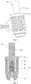
FIG. 1 is a cross-sectional view of an electronic smoking set in accordance with one embodiment of the present disclosure; -
FIG. 2 is a cross-sectional view of the electronic smoking set without the power supply module in accordance with one embodiment of the present disclosure; -
FIG. 3 is an exploded view of the electronic smoking set without the power supply module in accordance with one embodiment of the present disclosure; -
FIG. 4 illustrates the heating device in the electronic smoking set inFIG. 1 ; -
FIG.5 is an exploded view of the heating device in the electronic smoking set inFIG. 1 ; -
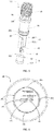
FIG. 6 is a top view of the heating device in the electronic smoking set inFIG. 1 ; -
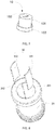
FIG. 7 is an isometric view of the base in the heating device; -
FIG. 8 illustrates connection between a supporter and a first heating element in the heating device inFIG. 4 ; -
FIG. 9 illustrates connection between the base and a second heating element in the heating device inFIG. 4 ; -
FIG. 10 illustrates the second heating element in the heating device inFIG. 4 ; -
FIG. 11 illustrates connection between the electromagnetic inductive coil inFIG. 4 and the power supply module inFIG. 1 . -
FIG. 12 is a block diagram illustrating the power supply module in the electronic smoking set inFIG. 1 . - The structure and operating principle of the above heating element with temperature control and the low-temperature baked smoking set having same are illustrated below, mainly shown from
FIG. 1 to FIG. 12 in further detail using exemplary embodiments. - Referring to
FIGs. 1-3 , which provide an electronic smoking set in accordance with embodiments of the present disclosure. Theelectronic smoking set 300 includes aheating device 100, apower supply module 110 and atobacco cigarette 200. As used supra, thepower supply module 110 is coupled with the electromagneticinductive coil 50 in theheating device 100 and configured for supplying an alternating current to the electromagneticinductive coil 50. Theheating device 100 is configured to heat thetobacco cigarette 200. Thetobacco cigarette 200 may be one or more tobacco shaped in rods. Thetobacco cigarette 200 is disposed inside theheating device 100. More specifically, theheating device 100 has achamber 201 therein configured for receiving thetobacco cigarette 200. Theheating device 100 is configured to heat thetobacco cigarette 200, making thetobacco cigarette 200 to generate an aerosol drawn directly in combusting and non-burning methods, that is, thetobacco cigarette 200 doesn't need to be burnt to generate tar etc. some toxic gas, therefore decreasing the detrimental on the smokers' health. - The
heating device 100 will be described in detail hereinafter in accordance with embodiments of the present disclosure. - With reference to
FIGs. 4 to 6 , together withFIG. 2 , theheating device 100 includes abase 10, asupporter 20, at least onefirst heating element 30, asecond heating element 40 and anelectromagnetic induction coil 50. As used herein, thesupporter 20 is installed on thebase 10. Thesupporter 20 has achamber 201 therein configured for receiving thetobacco cigarette 200. Theelectromagnetic induction coil 50 is wound around thesupporter 20 and configured for generating an alternative magnetic field in thechamber 201, such that the at least onefirst heating element 30 andsecond heating element 40 generate vortexes respectively. The at least onefirst heating element 30 is disposed in thechamber 201, when thetobacco cigarette 200 is received in thechamber 201, the at least onefirst heating element 30 contacts an outer surface of thetobacco cigarette 200 and generates a vortex in the alternative magnetic field to heat thetobacco cigarette 200, that means, heating outside thetobacco cigarette 200 directly. Moreover, the at least onefirst heating element 30 is disposed around a periphery of thesecond heating element 40 to form acut 304 extending along an axial direction of theinduction coil 50, which may ensure sufficient usage of the electromagnetic flux without influencing thesecond heating element 40 to absorb and transform the electromagnetic flux. The electromagnetic inductive lines in thechamber 201 passing through thechamber 201 are parallel with the axial direction of theinduction coil 50. Along a circumferential direction of thechamber 201, where thecut 304 is located the electromagnetic inductive lines pass through thecut 304 to be concentrated on thesecond heating element 40, but where thefirst heating element 30 is located the electromagnetic inductive lines are concentrated on thefirst heating element 30. Thesecond heating element 40 is installed on thebase 10, when thetobacco cigarette 200 is received inside thechamber 201, thesecond heating element 40 is inserted into thetobacco cigarette 200 and generates a vertex to heat thetobacco cigarette 200, that means, heating thetobacco cigarette 200 inside directly thus to heat thetobacco cigarette 200 from inside to outside, with while the at least onefirst heating element 30 is heating thetobacco cigarette 200 from outside to inside, therefore thetobacco cigarette 200 is heated evenly. Moreover, since thefirst heating element 30 has acut 304 for ensuring thesecond heating element 40 to absorb sufficient electromagnetic flux, such that improving the heating efficiency of thesecond heating element 40 heating thetobacco cigarette 200, further, making sure thetobacco cigarette 200 is heated evenly so a taste of theelectronic cigarette 300 is improved. - With reference to
FIG. 7 , thebase 10 includes abulge part 101 and asubstrate 102, thebulge part 101 is integral with thesubstrate 102. More specifically, thebulge part 101 and thesubstrate 102 are integral as a whole by casting or stamping technologies etc. no limitation herein. In some embodiments, thebulge part 101 may be detachably connected with thesubstrate 102. As used herein, thebulge part 101 is roughly a cylindrical structure; thebulge part 101 is inserted into thechamber 201 of thesupporter 20 to install thesupporter 20 on thebase 10. Thebase 10 has afastening structure 103 for fixing thesecond heating element 40 on thebase 10. More specifically, thebulge part 101 has thefastening structure 103, and thefastening structure 103 is a groove, one end of thesecond heating element 40 is inserted into the groove, so thesecond heating element 40 is fixed on thebase 10. In some embodiments, thesecond heating element 40 may be fixed on thebase 10 via other methods, such as screw threads etc. - Referring to
FIGs. 4 to 6 , thesupporter 20 is roughly a hollow cylinder, an inner diameter of thesupporter 20 is roughly larger than an outer diameter of thebulge part 101, so thebulge part 101 is inserted into thesupporter 20, and thesupporter 20 is installed in thebase 10. Since thesupporter 20 is hollow, thesupporter 20 has achamber 201 therein for receiving thetobacco cigarette 200. More specifically, part of thetobacco cigarette 200 is received into thechamber 201, remaining part of thetobacco cigarette 200 protrudes outside thechamber 201. - Referring
FIG. 8 , the at least onefirst heating element 30 is disposed in thechamber 201, more specifically, the inner wall of thesupporter 20 has aslot 202 for engaging with thefirst heating element 30 that is installable on thebase 20, so the at least onefirst heating element 30 is disposed in thechamber 201. When thetobacco cigarette 200 is received in thechamber 201, the at least onefirst heating element 30 is disposed between thetobacco cigarette 200 and thesupporter 20, and the at least onefirst heating element 30 contacts the outer surface of thetobacco cigarette 200 and generates a vertex in the magnetic field to heat thetobacco cigarette 200, that means, thetobacco cigarette 200 is heated from outside to inside, which is the first direction as shown inFIG. 6 . In the embodiments, the electromagnetic heating method is adopted to heat thetobacco cigarette 200, therefore, the at least onefirst heating element 30 is made by a metallic conductor, electromagnetic materials are preferred to bring a better effect of electromagnetic heating. In some embodiments, the at least onefirst heating element 30 is made of at least one or more selected from a group of iron powder, iron-nickel 50, sendust cores and MPP molypermalloy powder etc. - The at least one
first heating element 30 has acut 304 thereon extending along an axial direction of theelectromagnetic induction coil 50. More specifically, the at least onefirst heating element 30 includes two first heating element, and two first heating elements are spaced from each other by a predetermined distance along a circumferential direction of an inner wall of the chamber, thus forming thecut 304. Since theelectromagnetic induction coil 50 is provided in the embodiments of the present disclosure, thetobacco cigarette 200 is heated via the electromagnetic heating method. Therefore, to utilize the electromagnetic flux sufficiently and not to affect thesecond heating element 40 absorbing the electromagnetic flux, at least onefirst heating element 30 is needed to be wound around a periphery of thetobacco cigarette 200, forming thecut 304. For example, two first heating elements are disposed along the circumferential direction of the inner wall of thechamber 201, thus forming thecut 304, rather than a closed loop. As used herein, the number of thecuts 304 may be multiple, such as one, two, three or four etc. no limitation to the number of thecuts 304 herein. - More specifically, two first heating elements include a first arc-shaped
heating piece 301 and a second arc-shapedheating piece 302 matched with the outer surface of thetobacco cigarette 200. The first arc-shapedheating piece 301 and a second arc-shapedheating piece 302 are disposed symmetrically at two sides of thesecond heating element 40, thus forming thecut 304 that ensures thesecond heating element 40 to absorb electromagnetic inductive lines for transformation, twofirst heating elements 30 symmetrically set at two sides of thesecond heating element 40 may make thetobacco cigarette 200 available for heating evenly. - In some embodiments, the two first heating elements may be integrated as a whole. More specifically, the two first heating elements may be a sleeve, the side wall of the sleeve is provided with two or more than two grooves extending along the axial direction of the sleeve, thus forming the
cut 304. - Referring to
FIG. 9 and FIG. 10 , thesecond heating element 40 is installed on thebase 10; more specifically, one end of thesecond heating element 40 is inserted into the groove to fix thesecond heating element 40 on thebase 10. When thetobacco cigarette 200 is received in thechamber 201, thesecond heating element 40 is inserted into thetobacco cigarette 200 and generates a vertex in the alternating magnetic field to heat thetobacco cigarette 200, therefore thetobacco cigarette 200 is heated from inside to outside, which is the second direction as shown inFIG. 6 . The material of thesecond heating element 40 is similar with the at least onefirst heating element 30, that is thesecond heating element 40 is made by metallic conductor, permeability magnetic material is preferred which has better effect of electromagnetic inductive heating. For example, thesecond heating element 40 is made of at least one or more selected from a group of iron powder, iron-nickel 50, sendust cores and MPP molypermalloy powder etc. - The
second heating element 40 is a laminated structure with afirst surface 401 and asecond surface 402. As used herein, an area of thefirst surface 401 is larger than that of thesecond surface 402, thefirst surface 401 faces thecut 304. More specifically, thefirst surface 401 is perpendicular with a line connecting with two ends of the first arc-shapedheating piece 301, and thefirst surface 401 is perpendicular with a line connecting with two ends of the second arc-shapedheating piece 302, and thesecond surface 402 is parallel with a line connecting with two ends of the first arc-shapedheating piece 301, and thesecond surface 402 is parallel with a line connecting with two ends of the second arc-shapedheating piece 302. Since thesecond heating element 40 is plate-shaped structure, the area of thefirst surface 401 is larger than that of thesecond surface 402, therefore, thesecond heating element 40 generates more heat on thefirst surface 401 than thesecond surface 402. Meanwhile, since between the first arc-shapedheating element 301 and the second arc-shapedheating element 302 has acut 304, enabling temperature of the area near to the first arc-shapedheating element 301 and the second arc-shapedheating element 302 is higher than the temperature of the area near to thecut 304. By means of thefirst surface 401 perpendicular with the line connecting two ends of the first arc-shapedheating element 301, and thefirst surface 401 perpendicular with the line connecting two ends of the second arc-shapedheating element 302, thesecond surface 402 parallel with a line connecting two ends of the first arc-shapedheating piece 301, and thesecond surface 401 parallel with a line connecting two ends of the second arc-shapedheating piece 302, thetobacco cigarette 200 is further heated evenly, so as to improve the taste of the electronic smoking set 300. - Referring to
FIGs. 4 to 6 , theelectromagnetic induction coil 50 is wound around thesupporter 20; more specifically, thesupporter 20 has a first position stop 205 and a second position stop 206. Theelectromagnetic induction coil 50 is wound around thesupporter 20 between the first and second position stops 205, 206. Theelectromagnetic induction coil 50 is used to generate a changing magnetic field, such that the at leastfirst heating element 30 and thesecond heating element 40 generate vortexes. More specifically, when an alternating current is passing through theelectromagnetic induction coil 50, such as the fast changing high-frequency and high-voltage current passes through theelectromagnetic induction coil 50, it would generate fast changing alternative magnetic field, the at least onefirst heating element 30 and thesecond heating element 40 are disposed in the alternative magnetic field to do cutting motion for cutting alternative magnetic field lines to generate alternating current, that is the vortex. The vortex makes carriers of the at leastfirst heating element 50 and thesecond heating element 40 do high-speed and irregular motion, the carriers are crashing into one another and rubbing with one another to generate heat energy, so as to heat thetobacco cigarette 200. Theelectromagnetic induction coil 50 may be made by electricity conductive materials, such as, theelectromagnetic induction coil 50 may be made by good electricity conductor with cheap price such as copper wires and aluminum filaments etc. - Understandable, in some embodiments, two electromagnetic induction coils 50 are provided, including a first coil (not shown) and a second coil (not shown), the first coil and the second coil are wound around a periphery of the
supporter 20, and the number of the first coils and the second coils are different, so as to change heating speed of the at leastfirst heating element 50 and thesecond heating element 40, therefore the heating effect is more flexible. - Understandable, in some embodiments, an outer surface of the
electromagnetic induction coil 50 is coated with an insulating layer (not shown), the insulating layer is configured to avoid leakage of electricity through theelectromagnetic induction coil 50. The insulating layer is made by insulating materials such as at least one or more selected from a group of synthetic resins, epoxy resins, phenolic resins, UP-4250, polyimide plastic, energy-concentrated resins and polyimide etc. - The
heating device 100 further includes a heat insulating layer (not shown), the heat insulating layer is disposed between theelectromagnetic induction coil 50 and the at least onefirst heating element 30, the heat insulating layer is configured for reducing heat in thechamber 20 transferring outside. The heat insulating layer is made by heat insulating materials, such as at least one or more selected from a group of heat insulation glue, aerogel, asbestos, aluminium silicate and calcium silicate etc. The heat insulating layer makes the heat not easy to loss, and is more safe to use, therefore improving heat efficiency and effect of heat preservation. - The
heating device 100 further includes atemperature sensor 60, disposed on thesecond heating element 40. Thetemperature sensor 60 is used for temperature detecting. Thetemperature sensor 60 is used in a controller to send signals, the controller is used to control temperature of theheating device 100. As used herein, the controller is a controller allocated in theelectronic cigarette 300, or a controller allocated in an exterior apparatus such as a terminal apparatus. - It needs to be illustrated, in some embodiments, the
temperature sensor 60 may also be allocated on the at least onefirst heating element 30, or between the at least onfirst heating element 30 and thesecond heating element 40. - The
power supply module 110 provided by the embodiments of the present disclosure is described hereinafter. - Referring to
FIG. 11 and FIG. 12 , thepower supply module 110 is coupled with theelectromagnetic induction coil 50 to supply an alternating current to theelectromagnetic induction coil 50. Specifically, theelectromagnetic induction coil 50 includes afirst interface 501 and asecond interface 502; thepower supply module 110 may be coupled with thefirst interface 501 and thesecond interface 502, so as to be coupled with theelectromagnetic induction coil 50. Thus theelectromagnetic induction coil 50 generates electromagnetic induction. According to law of electromagnetic induction, when thepower supply module 110 supplies the alternating current to theelectromagnetic induction coil 50, theelectromagnetic induction coil 50 generates alternating current so as to generate the alternative magnetic field. The at least onefirst heating element 30 and thesecond heating element 40 are disposed in the alternative magnetic field, doing cutting motion, that is, cutting alternative magnetic inductive lines to generate the alternating current, namely a vortex, therefore heating thetobacco cigarette 200. - As used herein, the
power supply module 110 includes anUSB interface 1101, apower supply 1102, acontrol unit 1103, acharging circuit 1104, a dischargingcircuit 1105, avoltage detecting circuit 1106, twoswitches 1107, apower management circuit 1108 and aconverter 1109. Thepower supply 1102 is respectively coupled with thecharging circuit 1104 and the dischargingcircuit 1105. Further, aswitch 1107 is disposed between thepower supply 1102 and thecharging circuit 1104, and anotherswitch 1107 is disposed between thepower supply 1102 and the dischargingcircuit 1105. Thecharging circuit 1104 and the dischargingcircuit 1105 are both coupled with theUSB interface 1101, coupled with the exterior power supply via an USB interface. Thevoltage detecting circuit 1106 is coupled with theUSB interface 1101 to detect weather thepower supply module 110 is coupled with the exterior power supply. Thecontrol unit 1103 is respectively coupled with twoswitches 1107 and thevoltage detecting circuit 1106. Thedischarge circuit 1105 is coupled with thepower management circuit 1108; thepower management circuit 1108 is coupled with theconverter 1109. Theconverter 1109 is configured for changing DC (direct current) to AC (alternating current), theconverter 1109 is coupled with theelectromagnetic induction coil 50 to supply power to it. If thevoltage detecting circuit 1106 detects a voltage, that means thepower supply module 110 is coupled with the exterior power supply, so thevoltage detecting circuit 1106 sends signals to thecontrol unit 1103 sends signals, thecontrol unit 1103 receives that signal and controls theswitch 1107 between thepower supply 1102 and thecharging circuit 1104, from "off' state is changed into "on" state, the current of the exterior power supply charges thepower supply 1102. If thevoltage detecting circuit 1106 fails to detect the voltage, thecontrol unit 1103 receives that signal and controls theswitch 1107 between thepower supply 1102 and the dischargingcircuit 1105, that is, anotherswitch 1107, from "off' state is changed into "on" state. The current of thepower supply 1102 flows towards theconvertor 1109 from the dischargingcircuit 1105 and thepower management circuit 1108. Theconvertor 1109 changes DC to AC, thus supplying power to theelectromagnetic induction coil 50. - In terms of the
heating device 100 of the present disclosure, when the at least onefirst heating element 30 heats thetobacco cigarette 200 from outside to inside, while thesecond heating element 40 heats thetobacco cigarette 200 from inside to outside, therefore heating thetobacco cigarette 200 evenly. Moreover, since the at least onefirst heating element 30 has thecut 304 extending along the axial direction of theelectromagnetic induction coil 50, which may ensure thesecond heating element 40 to absorb and transform sufficient magnetic flux, so as to improve the heating efficiency of thesecond heating element 40, consequently improving heating efficiency to thetobacco cigarette 200, further making thetobacco cigarette 200 heated evenly, making taste consistent and improving the taste of theelectronic cigarette 300, eventually improving user experience. - Terminology used herein is for the purpose of describing particular embodiments only and is not intended to be limiting of the invention. Variations may be made to the embodiments and methods without departing from the scope of the disclosure which is defined by the appended claims. Accordingly, it is appropriate that the appended claims be construed broadly and in a manner consistent with the scope of the disclosure.
Claims (10)
- A heating device (100) for heating tobacco cigarette (200), comprising:a base (10);a supporter (20) disposed on the base (10), the supporter (20) comprising a chamber (201) therein, the chamber (201) being configured for receiving the tobacco cigarette (200);an electromagnetic induction coil (50) wound around the supporter (20) and configured for generating an alternative magnetic field in the chamber (201);at least one first heating element (30) disposed in the chamber (201); when the tobacco, cigarette (200) is disposed in the chamber (201) the at least one first heating element (30) contacts an outer surface of the tobacco cigarette (200) and is configured for generating a vortex in the alternative magnetic field to heat the tobacco cigarette (200); anda second heating element (40) disposed on the base (10); when the tobacco cigarette (200) is disposed in the chamber (201) , the second heating element (40) is inserted into the tobacco cigarette (200) and configured to generate a vortex in the alternative magnetic field to heat the tobacco cigarette (200);wherein, the at least one first heating element (30) is disposed around a periphery of the second heating element (40), and the at least one first heating element (30) forms a cut (304) extending along an axial direction of the electromagnetic induction coil (50).
- The heating device of claim 1, wherein the at least one first heating element (30) comprises two first heating elements; and
the two first heating elements are spaced from each other by a predetermined distance along a circumferential direction of an inner wall of the chamber (201), thus forming the cut (304). - The heating device of claim 2, wherein the two first heating elements comprise a first arc-shaped heating piece (301) and a second arc-shaped heating piece (302) matched with the outer surface of the tobacco cigarette (200), and the first arc-shaped heating piece (301) and the second arc-shaped heating piece (302) are symmetrically disposed at two sides of the second heating element.
- The heating device of claim 3, wherein the second heating element (40) is a plate-shaped structure with a first surface (401) and a second surface (402); the first surface (401) has a larger area than the second surface (402); the first surface (401) faces the cut (304).
- The heating device of claim 4, wherein the first surface (401) is perpendicular with a line connecting two ends of the first arc-shaped heating piece (301); and the first surface (401) is perpendicular with a line connecting two ends of the second arc-shaped heating piece (302); the second surface (402) is parallel with a line connecting two ends of the first arc-shaped heating piece (301); and the second surface (402) is parallel with a line connecting two ends of the second arc-shaped heating piece (302).
- The heating device of claim 1, wherein the heating device further comprises a heat insulating layer; the heat insulating layer is disposed between the electromagnetic inductive coil (50) and the at least one first heating element (30); the heat insulating layer is configured to reduce heat in the chamber transferring outside.
- The heating device of claim 1, wherein the base (10) comprises a bulge part (101) and a substrate, the bulge part (101) is inserted into the chamber of the supporter (20) to allow the supporter (20) to be installed in the base (10).
- The heating device of claim 1, wherein the base comprises (10) a fixing structure (103) configured to fix the second heating element (40) in the base (10).
- The heating device of claim 1, wherein the heating device further comprises a temperature sensor (60), the temperature sensor (60) is disposed on the second heating element (40) or the at least one first heating element (30), or between the at least one first heating element and the second heating element.
- A smoking set, comprising:a power supply module (110); anda heating device (100) according to any one of claims 1-9;wherein the power supply module (110) is coupled with the electromagnetic inductive coil (50) in the heating device (100) and configured for supplying an alternating current to the electromagnetic inductive coil (50).
Applications Claiming Priority (1)
| Application Number | Priority Date | Filing Date | Title |
|---|---|---|---|
| CN201820171493.9U CN207766584U (en) | 2018-01-31 | 2018-01-31 | A kind of heating device and electronic cigarette |
Publications (3)
| Publication Number | Publication Date |
|---|---|
| EP3469936A2 EP3469936A2 (en) | 2019-04-17 |
| EP3469936A3 EP3469936A3 (en) | 2019-07-24 |
| EP3469936B1 true EP3469936B1 (en) | 2021-10-20 |
Family
ID=63179891
Family Applications (1)
| Application Number | Title | Priority Date | Filing Date |
|---|---|---|---|
| EP19154281.0A Active EP3469936B1 (en) | 2018-01-31 | 2019-01-29 | Heating device and smoking set having same |
Country Status (5)
| Country | Link |
|---|---|
| US (1) | US11596177B2 (en) |
| EP (1) | EP3469936B1 (en) |
| JP (1) | JP6766192B2 (en) |
| KR (1) | KR102236045B1 (en) |
| CN (1) | CN207766584U (en) |
Families Citing this family (53)
| Publication number | Priority date | Publication date | Assignee | Title |
|---|---|---|---|---|
| US20180117268A1 (en) * | 2015-04-29 | 2018-05-03 | Poda Technologies Ltd. | Vaporizer, apparatus, device, and methods |
| US10925316B2 (en) * | 2015-06-10 | 2021-02-23 | Philip Morris Products S.A. | Electrical aerosol generating system |
| US10624392B2 (en) * | 2015-12-22 | 2020-04-21 | Altria Client Services Llc | Aerosol-generating system with motor |
| US10772354B2 (en) * | 2016-05-31 | 2020-09-15 | Altria Client Services Llc | Heater and wick assembly for an aerosol generating system |
| US10524508B2 (en) * | 2016-11-15 | 2020-01-07 | Rai Strategic Holdings, Inc. | Induction-based aerosol delivery device |
| US10834970B2 (en) * | 2016-12-02 | 2020-11-17 | VMR Products, LLC | Combination vaporizer |
| US10765148B2 (en) * | 2016-12-27 | 2020-09-08 | Altria Client Services Llc | E-vaping device including e-vaping case with sliding mechanism for initiating vapor generation |
| DE112017007475T5 (en) * | 2017-04-24 | 2020-03-12 | Japan Tobacco Inc. | AEROSOL GENERATING DEVICE, METHOD FOR CONTROLLING AN AEROSOL GENERATING DEVICE AND PROGRAM |
| US11094993B2 (en) * | 2018-08-10 | 2021-08-17 | Rai Strategic Holdings, Inc. | Charge circuitry for an aerosol delivery device |
| CN108783613A (en) * | 2018-09-10 | 2018-11-13 | 深圳博英特科技有限公司 | A kind of induction type electromagnetic heating electronic cigarette |
| JP2020058236A (en) * | 2018-10-04 | 2020-04-16 | 日本たばこ産業株式会社 | Inhalation component generating device, control circuit, and control method and control program of inhalation component generating device |
| GB2613265B (en) | 2018-10-19 | 2023-09-20 | Juul Labs Inc | Vaporizer power system |
| EA202191249A1 (en) * | 2018-11-26 | 2021-08-26 | ДжейТи ИНТЕРНЭШНЛ СА | INDUCTION HEATING UNIT FOR AEROSOL GENERATING DEVICE AND METHOD OF ITS MANUFACTURING |
| KR102199796B1 (en) * | 2018-12-11 | 2021-01-07 | 주식회사 케이티앤지 | Apparatus and system for generating aerosol by induction heating |
| KR102199793B1 (en) * | 2018-12-11 | 2021-01-07 | 주식회사 케이티앤지 | Apparatus for generating aerosol |
| KR102270185B1 (en) * | 2018-12-11 | 2021-06-28 | 주식회사 케이티앤지 | Apparatus for generating aerosol |
| CN113226083A (en) * | 2018-12-21 | 2021-08-06 | 音诺艾迪有限公司 | Particle generating device with induction heater |
| KR102253046B1 (en) * | 2019-03-05 | 2021-05-17 | 주식회사 케이티앤지 | Aerosol generating device and system, and manufacturing method of the aerosol generating device |
| WO2020182734A1 (en) * | 2019-03-11 | 2020-09-17 | Nicoventures Trading Limited | Apparatus for aerosol generating system |
| CN112167719A (en) * | 2019-07-04 | 2021-01-05 | 青岛颐中科技有限公司 | Low-temperature smoking set |
| KR102413550B1 (en) * | 2019-07-23 | 2022-06-27 | 주식회사 케이티앤지 | Heater assembly, method for manufacturing heater assembly and aerosol generating device including heater assembly |
| KR102392126B1 (en) * | 2019-08-02 | 2022-04-28 | 주식회사 케이티앤지 | Heating assembly, aerosol generating device and system comprising the same |
| WO2021053028A1 (en) * | 2019-09-19 | 2021-03-25 | Philip Morris Products S.A. | Induction heater enabling lateral airflow |
| KR20220043195A (en) * | 2019-09-19 | 2022-04-05 | 필립모리스 프로덕츠 에스.에이. | Induction heater with central and peripheral susceptors |
| PL4037504T3 (en) * | 2019-10-02 | 2023-11-13 | Philip Morris Products S.A. | Susceptor heating element formed from shape memory material for aerosol generating device |
| JP6816240B1 (en) * | 2019-10-28 | 2021-01-20 | 日本たばこ産業株式会社 | Control device for aerosol aspirator and aerosol aspirator |
| KR102423895B1 (en) | 2019-11-25 | 2022-07-21 | 주식회사 케이티앤지 | Heater assembly, aerosol generating device and aerosol generating system |
| CN110731541B (en) * | 2019-12-05 | 2022-01-28 | 江苏中烟工业有限责任公司 | Roll type cigarette cartridge with heating device |
| US20230346030A1 (en) * | 2019-12-09 | 2023-11-02 | Shenzhen First Union Technology Co., Ltd. | Susceptor for aerosol generation device and aerosol generation device |
| CN212117076U (en) * | 2020-01-08 | 2020-12-11 | 深圳市合元科技有限公司 | Aerosol generator |
| CN113197348A (en) * | 2020-02-03 | 2021-08-03 | 深圳易佳特科技有限公司 | Electromagnetic induction heating control by temperature change tobacco flue-curing device |
| KR102436024B1 (en) * | 2020-02-26 | 2022-08-24 | 주식회사 케이티앤지 | Optical Module and Aerosol generating device comprising thereof |
| CN111278183A (en) | 2020-02-26 | 2020-06-12 | 深圳麦时科技有限公司 | Heating member and electromagnetic heating baking device |
| CN212233104U (en) * | 2020-03-26 | 2020-12-29 | 深圳麦克韦尔科技有限公司 | Aerosol generating device and electromagnetic heating assembly thereof |
| CN113508930A (en) * | 2020-04-11 | 2021-10-19 | 深圳市合元科技有限公司 | Aerosol generating device and susceptor |
| KR102427858B1 (en) * | 2020-04-22 | 2022-08-01 | 주식회사 케이티앤지 | Aerosol generating device |
| KR102509092B1 (en) * | 2020-05-20 | 2023-03-10 | 주식회사 케이티앤지 | Heater assembly and manufacturing method thereof |
| GB202016483D0 (en) * | 2020-10-16 | 2020-12-02 | Nicoventures Holdings Ltd | Aerosol provision device and heating system |
| GB202016479D0 (en) * | 2020-10-16 | 2020-12-02 | Nicoventures Trading Ltd | Aerosol provision device |
| KR102508888B1 (en) * | 2020-10-21 | 2023-03-10 | 주식회사 아이티엠반도체 | Double heating type heat-emitting apparatus for electronic cigarette, heat-emitting method and electronic cigarette |
| CN112790441A (en) * | 2020-12-30 | 2021-05-14 | 深圳市基克纳科技有限公司 | Heating assembly of atomizing device |
| TW202235017A (en) * | 2021-02-02 | 2022-09-16 | 瑞士商傑太日煙國際股份有限公司 | An aerosol generating device and an aerosol generating system |
| TW202231197A (en) * | 2021-02-02 | 2022-08-16 | 瑞士商傑太日煙國際股份有限公司 | An aerosol generating device and an aerosol generating system |
| TW202231200A (en) * | 2021-02-02 | 2022-08-16 | 瑞士商傑太日煙國際股份有限公司 | An induction heating assembly for an aerosol generating device |
| TW202235018A (en) * | 2021-02-02 | 2022-09-16 | 瑞士商傑太日煙國際股份有限公司 | An induction heating assembly for an aerosol generating device |
| TW202231196A (en) * | 2021-02-02 | 2022-08-16 | 瑞士商傑太日煙國際股份有限公司 | An aerosol generating device and an aerosol generating system |
| KR20230142485A (en) * | 2021-02-02 | 2023-10-11 | 제이티 인터내셔널 소시에떼 아노님 | Aerosol generating device |
| GB202108806D0 (en) * | 2021-06-18 | 2021-08-04 | Nicoventures Trading Ltd | Aerosol provision device |
| CN113367410A (en) * | 2021-06-28 | 2021-09-10 | 惠州市新泓威科技有限公司 | Aerosol generating device capable of generating heat through electromagnetic induction |
| WO2023286143A1 (en) * | 2021-07-13 | 2023-01-19 | 日本たばこ産業株式会社 | Aerosol generation system |
| WO2023016767A1 (en) * | 2021-08-12 | 2023-02-16 | Jt International S.A. | Heat-not-burn aerosol-generating device comprising a transparent heater |
| CN113647697A (en) * | 2021-08-23 | 2021-11-16 | 深圳麦克韦尔科技有限公司 | Heater and heating atomization device |
| CN114223965A (en) * | 2021-12-24 | 2022-03-25 | 普维思信(深圳)科技有限公司 | Non-combustible electronic smoking set based on electromagnetic induction heating |
Family Cites Families (6)
| Publication number | Priority date | Publication date | Assignee | Title |
|---|---|---|---|---|
| US585310A (en) * | 1897-06-29 | Alternating-current electric heater | ||
| JP6026556B2 (en) * | 2011-12-30 | 2016-11-16 | フィリップ・モーリス・プロダクツ・ソシエテ・アノニム | Aerosol generator with improved temperature distribution |
| GB2546934B (en) * | 2014-11-11 | 2018-04-11 | Jt Int Sa | Electronic vapour inhalers |
| US20170055580A1 (en) * | 2015-08-31 | 2017-03-02 | British American Tobacco (Investments) Limited | Apparatus for heating smokable material |
| US20170119047A1 (en) * | 2015-10-30 | 2017-05-04 | British American Tobacco (Investments) Limited | Article for Use with Apparatus for Heating Smokable Material |
| CN107454700A (en) * | 2017-08-22 | 2017-12-08 | 苏州三桓电子科技有限公司 | Contactless inductive heating body is in preparing the purposes in mist and/or cigarette generating means |
-
2018
- 2018-01-31 CN CN201820171493.9U patent/CN207766584U/en active Active
-
2019
- 2019-01-18 JP JP2019006983A patent/JP6766192B2/en active Active
- 2019-01-29 EP EP19154281.0A patent/EP3469936B1/en active Active
- 2019-01-29 KR KR1020190011086A patent/KR102236045B1/en active IP Right Grant
- 2019-01-31 US US16/262,936 patent/US11596177B2/en active Active
Non-Patent Citations (1)
| Title |
|---|
| None * |
Also Published As
| Publication number | Publication date |
|---|---|
| JP2019134701A (en) | 2019-08-15 |
| KR102236045B1 (en) | 2021-04-02 |
| EP3469936A3 (en) | 2019-07-24 |
| JP6766192B2 (en) | 2020-10-07 |
| KR20190093147A (en) | 2019-08-08 |
| CN207766584U (en) | 2018-08-24 |
| EP3469936A2 (en) | 2019-04-17 |
| US20190230987A1 (en) | 2019-08-01 |
| US11596177B2 (en) | 2023-03-07 |
Similar Documents
| Publication | Publication Date | Title |
|---|---|---|
| EP3469936B1 (en) | Heating device and smoking set having same | |
| EP3424353B1 (en) | Vaporizer and low-temperature smoking set | |
| KR102229937B1 (en) | Electromagnetic heating device and smoking set having same | |
| RU2728518C1 (en) | Induction coil assembly | |
| EP3476231B1 (en) | Aerosol generating device capable of adjusting heating area | |
| CN111512699B (en) | Induction heating assembly for a steam generating device | |
| RU2739844C2 (en) | Wireless charging system for charging a charged electric power source of a heating device for aerosol-generating articles | |
| CN207754555U (en) | A kind of heating device and smoking set | |
| KR20220119523A (en) | Aerosol provision device | |
| CA3132774A1 (en) | Aerosol provision device | |
| CA3120777A1 (en) | Induction heating assembly for an aerosol generating device and a method of manufacturing the same | |
| CN211860585U (en) | Heating member and electromagnetic heating baking device | |
| KR20220113769A (en) | Induction heating aerosol generating device with multi-wire induction coil | |
| CN205002174U (en) | Electromagnetic oven | |
| TW200719361A (en) | Power inductor | |
| CN215736934U (en) | Cage type external magnetic shielding electromagnetic induction heating smoking set | |
| TWI254598B (en) | Apparatus for inductive and resistive heating of an object | |
| CN116831331A (en) | Electromagnetic smoking set structure of sectional type coil | |
| CN113397225A (en) | Cage type external magnetic shielding electromagnetic induction heating smoking set | |
| KR20220002632A (en) | aerosol delivery device | |
| JPH0650669B2 (en) | Induction heating device for electromagnetic cooker | |
| TW363128B (en) | Apparatus for measuring electric current |
Legal Events
| Date | Code | Title | Description |
|---|---|---|---|
| PUAI | Public reference made under article 153(3) epc to a published international application that has entered the european phase |
Free format text: ORIGINAL CODE: 0009012 |
|
| STAA | Information on the status of an ep patent application or granted ep patent |
Free format text: STATUS: REQUEST FOR EXAMINATION WAS MADE |
|
| 17P | Request for examination filed |
Effective date: 20190225 |
|
| AK | Designated contracting states |
Kind code of ref document: A2 Designated state(s): AL AT BE BG CH CY CZ DE DK EE ES FI FR GB GR HR HU IE IS IT LI LT LU LV MC MK MT NL NO PL PT RO RS SE SI SK SM TR |
|
| AX | Request for extension of the european patent |
Extension state: BA ME |
|
| PUAL | Search report despatched |
Free format text: ORIGINAL CODE: 0009013 |
|
| AK | Designated contracting states |
Kind code of ref document: A3 Designated state(s): AL AT BE BG CH CY CZ DE DK EE ES FI FR GB GR HR HU IE IS IT LI LT LU LV MC MK MT NL NO PL PT RO RS SE SI SK SM TR |
|
| AX | Request for extension of the european patent |
Extension state: BA ME |
|
| RIC1 | Information provided on ipc code assigned before grant |
Ipc: H05B 6/10 20060101ALI20190618BHEP Ipc: A24F 47/00 20060101AFI20190618BHEP |
|
| STAA | Information on the status of an ep patent application or granted ep patent |
Free format text: STATUS: EXAMINATION IS IN PROGRESS |
|
| STAA | Information on the status of an ep patent application or granted ep patent |
Free format text: STATUS: EXAMINATION IS IN PROGRESS |
|
| 17Q | First examination report despatched |
Effective date: 20201019 |
|
| REG | Reference to a national code |
Ref country code: DE Ref legal event code: R079 Ref document number: 602019008392 Country of ref document: DE Free format text: PREVIOUS MAIN CLASS: A24F0047000000 Ipc: A24F0040465000 |
|
| GRAP | Despatch of communication of intention to grant a patent |
Free format text: ORIGINAL CODE: EPIDOSNIGR1 |
|
| STAA | Information on the status of an ep patent application or granted ep patent |
Free format text: STATUS: GRANT OF PATENT IS INTENDED |
|
| RIC1 | Information provided on ipc code assigned before grant |
Ipc: A24F 40/465 20200101AFI20210430BHEP |
|
| INTG | Intention to grant announced |
Effective date: 20210526 |
|
| GRAS | Grant fee paid |
Free format text: ORIGINAL CODE: EPIDOSNIGR3 |
|
| GRAA | (expected) grant |
Free format text: ORIGINAL CODE: 0009210 |
|
| STAA | Information on the status of an ep patent application or granted ep patent |
Free format text: STATUS: THE PATENT HAS BEEN GRANTED |
|
| AK | Designated contracting states |
Kind code of ref document: B1 Designated state(s): AL AT BE BG CH CY CZ DE DK EE ES FI FR GB GR HR HU IE IS IT LI LT LU LV MC MK MT NL NO PL PT RO RS SE SI SK SM TR |
|
| REG | Reference to a national code |
Ref country code: GB Ref legal event code: FG4D |
|
| REG | Reference to a national code |
Ref country code: CH Ref legal event code: EP |
|
| REG | Reference to a national code |
Ref country code: DE Ref legal event code: R096 Ref document number: 602019008392 Country of ref document: DE |
|
| REG | Reference to a national code |
Ref country code: IE Ref legal event code: FG4D |
|
| REG | Reference to a national code |
Ref country code: AT Ref legal event code: REF Ref document number: 1439178 Country of ref document: AT Kind code of ref document: T Effective date: 20211115 |
|
| REG | Reference to a national code |
Ref country code: LT Ref legal event code: MG9D |
|
| REG | Reference to a national code |
Ref country code: NL Ref legal event code: MP Effective date: 20211020 |
|
| REG | Reference to a national code |
Ref country code: AT Ref legal event code: MK05 Ref document number: 1439178 Country of ref document: AT Kind code of ref document: T Effective date: 20211020 |
|
| PG25 | Lapsed in a contracting state [announced via postgrant information from national office to epo] |
Ref country code: RS Free format text: LAPSE BECAUSE OF FAILURE TO SUBMIT A TRANSLATION OF THE DESCRIPTION OR TO PAY THE FEE WITHIN THE PRESCRIBED TIME-LIMIT Effective date: 20211020 Ref country code: LT Free format text: LAPSE BECAUSE OF FAILURE TO SUBMIT A TRANSLATION OF THE DESCRIPTION OR TO PAY THE FEE WITHIN THE PRESCRIBED TIME-LIMIT Effective date: 20211020 Ref country code: FI Free format text: LAPSE BECAUSE OF FAILURE TO SUBMIT A TRANSLATION OF THE DESCRIPTION OR TO PAY THE FEE WITHIN THE PRESCRIBED TIME-LIMIT Effective date: 20211020 Ref country code: BG Free format text: LAPSE BECAUSE OF FAILURE TO SUBMIT A TRANSLATION OF THE DESCRIPTION OR TO PAY THE FEE WITHIN THE PRESCRIBED TIME-LIMIT Effective date: 20220120 Ref country code: AT Free format text: LAPSE BECAUSE OF FAILURE TO SUBMIT A TRANSLATION OF THE DESCRIPTION OR TO PAY THE FEE WITHIN THE PRESCRIBED TIME-LIMIT Effective date: 20211020 |
|
| PG25 | Lapsed in a contracting state [announced via postgrant information from national office to epo] |
Ref country code: IS Free format text: LAPSE BECAUSE OF FAILURE TO SUBMIT A TRANSLATION OF THE DESCRIPTION OR TO PAY THE FEE WITHIN THE PRESCRIBED TIME-LIMIT Effective date: 20220220 Ref country code: SE Free format text: LAPSE BECAUSE OF FAILURE TO SUBMIT A TRANSLATION OF THE DESCRIPTION OR TO PAY THE FEE WITHIN THE PRESCRIBED TIME-LIMIT Effective date: 20211020 Ref country code: PT Free format text: LAPSE BECAUSE OF FAILURE TO SUBMIT A TRANSLATION OF THE DESCRIPTION OR TO PAY THE FEE WITHIN THE PRESCRIBED TIME-LIMIT Effective date: 20220221 Ref country code: PL Free format text: LAPSE BECAUSE OF FAILURE TO SUBMIT A TRANSLATION OF THE DESCRIPTION OR TO PAY THE FEE WITHIN THE PRESCRIBED TIME-LIMIT Effective date: 20211020 Ref country code: NO Free format text: LAPSE BECAUSE OF FAILURE TO SUBMIT A TRANSLATION OF THE DESCRIPTION OR TO PAY THE FEE WITHIN THE PRESCRIBED TIME-LIMIT Effective date: 20220120 Ref country code: NL Free format text: LAPSE BECAUSE OF FAILURE TO SUBMIT A TRANSLATION OF THE DESCRIPTION OR TO PAY THE FEE WITHIN THE PRESCRIBED TIME-LIMIT Effective date: 20211020 Ref country code: LV Free format text: LAPSE BECAUSE OF FAILURE TO SUBMIT A TRANSLATION OF THE DESCRIPTION OR TO PAY THE FEE WITHIN THE PRESCRIBED TIME-LIMIT Effective date: 20211020 Ref country code: HR Free format text: LAPSE BECAUSE OF FAILURE TO SUBMIT A TRANSLATION OF THE DESCRIPTION OR TO PAY THE FEE WITHIN THE PRESCRIBED TIME-LIMIT Effective date: 20211020 Ref country code: GR Free format text: LAPSE BECAUSE OF FAILURE TO SUBMIT A TRANSLATION OF THE DESCRIPTION OR TO PAY THE FEE WITHIN THE PRESCRIBED TIME-LIMIT Effective date: 20220121 Ref country code: ES Free format text: LAPSE BECAUSE OF FAILURE TO SUBMIT A TRANSLATION OF THE DESCRIPTION OR TO PAY THE FEE WITHIN THE PRESCRIBED TIME-LIMIT Effective date: 20211020 |
|
| REG | Reference to a national code |
Ref country code: DE Ref legal event code: R097 Ref document number: 602019008392 Country of ref document: DE |
|
| PG25 | Lapsed in a contracting state [announced via postgrant information from national office to epo] |
Ref country code: SM Free format text: LAPSE BECAUSE OF FAILURE TO SUBMIT A TRANSLATION OF THE DESCRIPTION OR TO PAY THE FEE WITHIN THE PRESCRIBED TIME-LIMIT Effective date: 20211020 Ref country code: SK Free format text: LAPSE BECAUSE OF FAILURE TO SUBMIT A TRANSLATION OF THE DESCRIPTION OR TO PAY THE FEE WITHIN THE PRESCRIBED TIME-LIMIT Effective date: 20211020 Ref country code: RO Free format text: LAPSE BECAUSE OF FAILURE TO SUBMIT A TRANSLATION OF THE DESCRIPTION OR TO PAY THE FEE WITHIN THE PRESCRIBED TIME-LIMIT Effective date: 20211020 Ref country code: EE Free format text: LAPSE BECAUSE OF FAILURE TO SUBMIT A TRANSLATION OF THE DESCRIPTION OR TO PAY THE FEE WITHIN THE PRESCRIBED TIME-LIMIT Effective date: 20211020 Ref country code: DK Free format text: LAPSE BECAUSE OF FAILURE TO SUBMIT A TRANSLATION OF THE DESCRIPTION OR TO PAY THE FEE WITHIN THE PRESCRIBED TIME-LIMIT Effective date: 20211020 Ref country code: CZ Free format text: LAPSE BECAUSE OF FAILURE TO SUBMIT A TRANSLATION OF THE DESCRIPTION OR TO PAY THE FEE WITHIN THE PRESCRIBED TIME-LIMIT Effective date: 20211020 |
|
| PLBE | No opposition filed within time limit |
Free format text: ORIGINAL CODE: 0009261 |
|
| STAA | Information on the status of an ep patent application or granted ep patent |
Free format text: STATUS: NO OPPOSITION FILED WITHIN TIME LIMIT |
|
| PG25 | Lapsed in a contracting state [announced via postgrant information from national office to epo] |
Ref country code: MC Free format text: LAPSE BECAUSE OF FAILURE TO SUBMIT A TRANSLATION OF THE DESCRIPTION OR TO PAY THE FEE WITHIN THE PRESCRIBED TIME-LIMIT Effective date: 20211020 |
|
| REG | Reference to a national code |
Ref country code: CH Ref legal event code: PL |
|
| 26N | No opposition filed |
Effective date: 20220721 |
|
| REG | Reference to a national code |
Ref country code: BE Ref legal event code: MM Effective date: 20220131 |
|
| PG25 | Lapsed in a contracting state [announced via postgrant information from national office to epo] |
Ref country code: LU Free format text: LAPSE BECAUSE OF NON-PAYMENT OF DUE FEES Effective date: 20220129 Ref country code: AL Free format text: LAPSE BECAUSE OF FAILURE TO SUBMIT A TRANSLATION OF THE DESCRIPTION OR TO PAY THE FEE WITHIN THE PRESCRIBED TIME-LIMIT Effective date: 20211020 |
|
| PG25 | Lapsed in a contracting state [announced via postgrant information from national office to epo] |
Ref country code: SI Free format text: LAPSE BECAUSE OF FAILURE TO SUBMIT A TRANSLATION OF THE DESCRIPTION OR TO PAY THE FEE WITHIN THE PRESCRIBED TIME-LIMIT Effective date: 20211020 Ref country code: BE Free format text: LAPSE BECAUSE OF NON-PAYMENT OF DUE FEES Effective date: 20220131 |
|
| PG25 | Lapsed in a contracting state [announced via postgrant information from national office to epo] |
Ref country code: LI Free format text: LAPSE BECAUSE OF NON-PAYMENT OF DUE FEES Effective date: 20220131 Ref country code: CH Free format text: LAPSE BECAUSE OF NON-PAYMENT OF DUE FEES Effective date: 20220131 |
|
| PG25 | Lapsed in a contracting state [announced via postgrant information from national office to epo] |
Ref country code: IE Free format text: LAPSE BECAUSE OF NON-PAYMENT OF DUE FEES Effective date: 20220129 |
|
| PGFP | Annual fee paid to national office [announced via postgrant information from national office to epo] |
Ref country code: FR Payment date: 20230125 Year of fee payment: 5 |
|
| PG25 | Lapsed in a contracting state [announced via postgrant information from national office to epo] |
Ref country code: IT Free format text: LAPSE BECAUSE OF FAILURE TO SUBMIT A TRANSLATION OF THE DESCRIPTION OR TO PAY THE FEE WITHIN THE PRESCRIBED TIME-LIMIT Effective date: 20211020 |
|
| PGFP | Annual fee paid to national office [announced via postgrant information from national office to epo] |
Ref country code: GB Payment date: 20230123 Year of fee payment: 5 Ref country code: DE Payment date: 20230112 Year of fee payment: 5 |
|
| PG25 | Lapsed in a contracting state [announced via postgrant information from national office to epo] |
Ref country code: HU Free format text: LAPSE BECAUSE OF FAILURE TO SUBMIT A TRANSLATION OF THE DESCRIPTION OR TO PAY THE FEE WITHIN THE PRESCRIBED TIME-LIMIT; INVALID AB INITIO Effective date: 20190129 |