KR20220113769A - Induction heating aerosol generating device with multi-wire induction coil - Google Patents
Induction heating aerosol generating device with multi-wire induction coil Download PDFInfo
- Publication number
- KR20220113769A KR20220113769A KR1020227023623A KR20227023623A KR20220113769A KR 20220113769 A KR20220113769 A KR 20220113769A KR 1020227023623 A KR1020227023623 A KR 1020227023623A KR 20227023623 A KR20227023623 A KR 20227023623A KR 20220113769 A KR20220113769 A KR 20220113769A
- Authority
- KR
- South Korea
- Prior art keywords
- aerosol
- composite cable
- section
- layer
- cavity
- Prior art date
Links
Images


Classifications
-
- A—HUMAN NECESSITIES
- A24—TOBACCO; CIGARS; CIGARETTES; SIMULATED SMOKING DEVICES; SMOKERS' REQUISITES
- A24F—SMOKERS' REQUISITES; MATCH BOXES; SIMULATED SMOKING DEVICES
- A24F40/00—Electrically operated smoking devices; Component parts thereof; Manufacture thereof; Maintenance or testing thereof; Charging means specially adapted therefor
- A24F40/40—Constructional details, e.g. connection of cartridges and battery parts
- A24F40/46—Shape or structure of electric heating means
- A24F40/465—Shape or structure of electric heating means specially adapted for induction heating
-
- H—ELECTRICITY
- H05—ELECTRIC TECHNIQUES NOT OTHERWISE PROVIDED FOR
- H05B—ELECTRIC HEATING; ELECTRIC LIGHT SOURCES NOT OTHERWISE PROVIDED FOR; CIRCUIT ARRANGEMENTS FOR ELECTRIC LIGHT SOURCES, IN GENERAL
- H05B6/00—Heating by electric, magnetic or electromagnetic fields
- H05B6/02—Induction heating
- H05B6/10—Induction heating apparatus, other than furnaces, for specific applications
- H05B6/105—Induction heating apparatus, other than furnaces, for specific applications using a susceptor
-
- H—ELECTRICITY
- H05—ELECTRIC TECHNIQUES NOT OTHERWISE PROVIDED FOR
- H05B—ELECTRIC HEATING; ELECTRIC LIGHT SOURCES NOT OTHERWISE PROVIDED FOR; CIRCUIT ARRANGEMENTS FOR ELECTRIC LIGHT SOURCES, IN GENERAL
- H05B6/00—Heating by electric, magnetic or electromagnetic fields
- H05B6/02—Induction heating
- H05B6/36—Coil arrangements
- H05B6/362—Coil arrangements with flat coil conductors
-
- H—ELECTRICITY
- H05—ELECTRIC TECHNIQUES NOT OTHERWISE PROVIDED FOR
- H05B—ELECTRIC HEATING; ELECTRIC LIGHT SOURCES NOT OTHERWISE PROVIDED FOR; CIRCUIT ARRANGEMENTS FOR ELECTRIC LIGHT SOURCES, IN GENERAL
- H05B6/00—Heating by electric, magnetic or electromagnetic fields
- H05B6/02—Induction heating
- H05B6/36—Coil arrangements
- H05B6/365—Coil arrangements using supplementary conductive or ferromagnetic pieces
-
- A—HUMAN NECESSITIES
- A24—TOBACCO; CIGARS; CIGARETTES; SIMULATED SMOKING DEVICES; SMOKERS' REQUISITES
- A24F—SMOKERS' REQUISITES; MATCH BOXES; SIMULATED SMOKING DEVICES
- A24F40/00—Electrically operated smoking devices; Component parts thereof; Manufacture thereof; Maintenance or testing thereof; Charging means specially adapted therefor
- A24F40/20—Devices using solid inhalable precursors
-
- A—HUMAN NECESSITIES
- A24—TOBACCO; CIGARS; CIGARETTES; SIMULATED SMOKING DEVICES; SMOKERS' REQUISITES
- A24F—SMOKERS' REQUISITES; MATCH BOXES; SIMULATED SMOKING DEVICES
- A24F40/00—Electrically operated smoking devices; Component parts thereof; Manufacture thereof; Maintenance or testing thereof; Charging means specially adapted therefor
- A24F40/70—Manufacture
Abstract
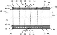
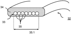
본 발명은 에어로졸 형성 기재(97)를 유도 가열함으로써 에어로졸을 발생시키기 위한 에어로졸 발생 장치(10)에 관한 것이다. 장치(10)는 공동(20)을 포함한 장치 하우징(19)을 포함한다. 공동은 가열될 에어로졸 형성 기재(97)의 적어도 일부분을 제거 가능하게 수용하도록 구성된다. 에어로졸 발생 장치(10)는, 공동(20) 내에 교번 자기장을 발생시키기 위한 유도 코일(31)을 포함한 유도 가열 배열부를 추가로 포함한다. 유도 코일(31)은 공동(20)의 적어도 일부분 주위에 배열된 복합 케이블(32)의 복수의 회전에 의해 형성된다. 복합 케이블(32)은 절연성 전도체 외피(34)에 적어도 부분적으로 매립된 전기 전도체(33)를 포함한다. 전기 전도체(33)는 서로 전기 접촉하고 있는 복수의 비절연 와이어(35)를 포함한다.The present invention relates to an aerosol-generating device (10) for generating an aerosol by induction heating an aerosol-forming substrate (97). The device 10 includes a device housing 19 including a cavity 20 . The cavity is configured to removably receive at least a portion of the aerosol-forming substrate 97 to be heated. The aerosol-generating device 10 further comprises an induction heating arrangement comprising an induction coil 31 for generating an alternating magnetic field within the cavity 20 . The induction coil 31 is formed by a plurality of turns of the composite cable 32 arranged around at least a portion of the cavity 20 . Composite cable 32 includes an electrical conductor 33 that is at least partially embedded in an insulative conductor sheath 34 . The electrical conductor 33 comprises a plurality of uninsulated wires 35 in electrical contact with each other.
Description
본 개시는 가열 시 흡입 가능한 에어로졸을 형성할 수 있는 기재와 함께 사용하기 위한 유도 가열 에어로졸 발생 장치에 관한 것이다. 본 발명은 또한 이러한 장치 및 에어로졸 발생 물품을 포함하는 에어로졸 발생 시스템에 관한 것이며, 이는 가열될 에어로졸 형성 기재를 포함한다.The present disclosure relates to an induction heating aerosol-generating device for use with a substrate capable of forming an inhalable aerosol upon heating. The present invention also relates to an aerosol-generating system comprising such a device and an aerosol-generating article, comprising an aerosol-forming substrate to be heated.
에어로졸 형성 기재를 유도 가열함으로써 흡입 가능한 에어로졸을 발생시키는 데 사용되는 에어로졸 발생 장치는 종래 기술로부터 일반적으로 공지되어 있다. 통상적으로, 이러한 장치는, 기재를 제거 가능하게 수용하기 위한 공동 및 공동 내에 교번 자기장을 생성하기 위한 유도 가열 배열부를 포함한다. 공동 내에, 필드는, 가열되도록 차례대로 기재와 열적으로 근접하거나 직접 물리적으로 접촉하여 배열된 서셉터 내의 발열 와전류 또는 히스테리시스 손실 중 적어도 하나를 유도하는 데 사용된다. 에어로졸 형성 기재 및 서셉터 모두는 공동 내에 수용 가능한 에어로졸 발생 물품의 일체형 부분일 수 있다. 대안적으로, 기재만이 물품에 포함될 수 있는 반면, 서셉터는 장치의 일부일 수 있다.Aerosol-generating devices used to generate an inhalable aerosol by induction heating of an aerosol-forming substrate are generally known from the prior art. Typically, such devices include a cavity for removably receiving a substrate and an induction heating arrangement for creating an alternating magnetic field within the cavity. Within the cavity, a field is used to induce at least one of exothermic eddy currents or hysteresis losses in a susceptor that in turn is arranged in thermal proximity or direct physical contact with the substrate to be heated. Both the aerosol-forming substrate and the susceptor may be an integral part of the aerosol-generating article receivable within the cavity. Alternatively, only the substrate may be included in the article, while the susceptor may be part of the device.
공동 내에 교번 자기장을 발생시키기 위해, 유도 가열 배열부는 일반적으로 공동의 적어도 일부분 주위에 배열된 전기 전도체의 복수의 회전에 의해 형성되는 유도 코일을 포함한다. 전형적으로, 공동의 부피는 단일 사용자 경험의 기재 부피에 대략적으로 대응하며, 따라서, 단지 수 입방센티미터이다. 이는 특히 휴대용 에어로졸 발생 장치에 대해 유효하다. 따라서, 유도 코일의 반경은 일반적으로 작다. 이는 코일의 제조를 다소 복잡하게 하거나 심지어 오류 발생을 쉽게 할 수 있으며, 따라서 결함 또는 비기능적 장치를 초래할 수 있다. 그 외에도, 예를 들어 이러한 장치에서 제한된 설치 공간을 최적으로 사용하기 위해, 전기 전도체의 특별한 단면 프로파일을 갖는 것이 종종 바람직할 것이다. 그러나, 직사각형 단면과 같은 특별한 단면을 갖는 전기 전도체는 일반적으로 표준 단면을 갖는 전기 전도체보다 더 비싸다. 이는, 이러한 장치의 제조를 보다 비용 집약적이게 할 수 있다.To generate an alternating magnetic field within the cavity, the induction heating arrangement generally includes an induction coil formed by a plurality of turns of an electrical conductor arranged around at least a portion of the cavity. Typically, the volume of the cavity roughly corresponds to the volume of the description of a single user experience, and thus is only a few cubic centimeters. This is particularly effective for portable aerosol-generating devices. Therefore, the radius of the induction coil is generally small. This can somewhat complicate the manufacture of the coil or even make it error prone, thus leading to a defective or non-functional device. Besides that, it will often be desirable to have a special cross-sectional profile of the electrical conductor, for example for optimal use of the limited installation space in such devices. However, an electrical conductor with a special cross-section, such as a rectangular cross-section, is generally more expensive than an electrical conductor with a standard cross-section. This can make the manufacture of such devices more cost-intensive.
따라서, 종래 기술의 해결책의 장점을 갖는 유도 가열 에어로졸 발생 장치 및 에어로졸 발생 시스템이 필요하면서도, 이들의 한계를 완화시킬 필요가 있다. 특히, 특히 낮은 고장율로 간단하고, 맞춤화되고, 비용 효과적인 방식으로 제조될 수 있는, 유도 코일 포함 유도 가열 에어로졸 발생 장치 및 시스템을 갖는 것이 바람직할 것이다.Accordingly, there is a need for induction heating aerosol-generating devices and aerosol-generating systems that have the advantages of prior art solutions, while easing their limitations. In particular, it would be desirable to have an induction heating aerosol-generating device and system comprising an induction coil that can be manufactured in a simple, customizable and cost effective manner, particularly with low failure rates.
본 발명에 따라, 에어로졸 형성 기재를 유도 가열하여 에어로졸을 발생시키기 위한 에어로졸 발생 장치가 제공되어 있다. 장치는 공동을 포함한 장치 하우징을 포함한다. 공동은 가열될 에어로졸 형성 기재의 적어도 일부분을 제거 가능하게 수용하도록 구성된다. 에어로졸 발생 장치는, 공동 내에 교번 자기장을 발생시키기 위한 유도 코일을 포함한 유도 가열 배열부를 추가로 포함한다. 유도 코일은 공동의 적어도 일부분 주위에 배열된 복합 케이블의 복수의 회전에 의해 형성된다. 복합 케이블은 절연성 전도체 외피에 적어도 부분적으로 매립된 전기 전도체를 포함한다. 전기 전도체는 서로 전기 접촉하고 있는 복수의 비절연 와이어를 포함한다.According to the present invention, there is provided an aerosol-generating device for generating an aerosol by induction heating an aerosol-forming substrate. The device includes a device housing including a cavity. The cavity is configured to removably receive at least a portion of the aerosol-forming substrate to be heated. The aerosol-generating device comprises an induction coil for generating an alternating magnetic field within the cavity. It further includes an induction heating arrangement. The induction coil is formed by a plurality of turns of the composite cable arranged around at least a portion of the cavity. The composite cable includes an electrical conductor that is at least partially embedded in an insulative conductor sheath. The electrical conductor includes a plurality of uninsulated wires in electrical contact with each other.
본 발명에 따르면, 단일 고체 와이어를 포함한 전기 전도체에 의해 형성된 유도 코일의 제한은, 주로 고체 와이어의 강성 특징으로 인한 것임을 인식하였다. 특히, 작은 권취 반경의 경우, 단일 고체 와이어를 포함한 전기 전도체의 권취는 와이어 재료에 높은 기계적 응력을 야기할 수 있으며, 이는 결과적으로 재료 피로 또는 재료 파손을 야기하여, 결함적이거나 심지어 비기능적인 코일을 야기할 수 있다. 대조적으로, 서로 전기 접촉하고 있는 복수의 비절연 와이어를 포함한 전도체는, 동일한 총 단면적의 고체 와이어를 포함한 전도체보다 더 가요성이다. 따라서, 복수의 비절연 와이어를 포함한 전기 전도체의 권취는, 재료 피로가 더 쉽고 덜하기 쉽거나 심지어 재료가 파손된다. 또한, 복수의 비절연 와이어는, 예컨대 전도체의 상이한 단면 형상을 실현하기 위해 다양한 구성으로 복합체 내에 배열될 수 있다. 유리하게는, 이는 맞춤형 단면 형상을 갖는 전기 전도체를 포함한 유도 케이블의 비용 효과적인 제조를 가능하게 한다.In accordance with the present invention, it has been recognized that the limitation of an induction coil formed by an electrical conductor comprising a single solid wire is primarily due to the rigid nature of the solid wire. Especially for small winding radii, winding of electrical conductors, including single solid wires, can cause high mechanical stress in the wire material, which in turn causes material fatigue or material breakage, resulting in defective or even non-functional coils. can cause In contrast, a conductor comprising a plurality of uninsulated wires in electrical contact with each other is more flexible than a conductor comprising solid wires of the same total cross-sectional area. Thus, winding of an electrical conductor comprising a plurality of non-insulated wires is more prone to material fatigue and less prone to material failure or even material failure. Further, a plurality of non-insulated wires may be arranged in the composite in various configurations to realize, for example, different cross-sectional shapes of the conductors. Advantageously, this enables cost-effective production of inductive cables comprising electrical conductors with customized cross-sectional shapes.
복수의 비절연 와이어는 서로 전기적으로 접촉하여, 예컨대 단일 전도체로서 작용하고, 특히 동일한 총 단면적을 갖는 단일 전도체와 실질적으로 동일한 전기 특성, 특히 실질적으로 동일한 전기 저항을 갖는다.A plurality of non-insulated wires are in electrical contact with each other, eg acting as a single conductor, and in particular have substantially the same electrical properties, in particular substantially the same electrical resistance, as a single conductor having the same total cross-sectional area.
서로 전기 접촉하고 있는 복수의 비절연 와이어는, 또한 와이어 가닥으로서 표시될 수 있다. 와이어 가닥은 함께 묶이거나 감싸져 복합 전도체를 형성하는 다수의 와이어로 구성된다. 따라서, 본 발명에 따른 전기 전도체는, 또한 서로 전기적으로 접촉하거는 복수의 비절연 와이어를 포함하거나 와이어 가닥을 포함하는 복합(전기) 전도체로서 표시될 수 있다.A plurality of uninsulated wires in electrical contact with each other may also be denoted as strands of wire. A wire strand consists of a number of wires that are bundled or wrapped together to form a composite conductor. Thus, the electrical conductor according to the invention can also be represented as a composite (electrical) conductor comprising a plurality of uninsulated wires or strands of wire which are in electrical contact with each other.
일반적으로, 복수의 비절연 와이어는 상이한 구성으로 배열될 수 있다. 와이어는 함께 묶이거나 함께 꼬이거나 함께 매듭되거나 함께 래핑될 수 있다. 마찬가지로, 와이어는 복합 케이블의 길이 연장부를 따라, 특히 서로 교차하지 않고 함께 매듭되거나 래핑되지 않고 서로 평행하게 진행할 수 있다. 병렬 배열에서, 인접한 와이어 사이의 접촉은 선을 따르지만, 몇 개의 지점만을 갖지는 않는다. 유리하게는, 이는 몇 개의 지점에서만의 접촉과 비교하여 와이어 사이의 전기 접촉을 증가시키는 더 큰 접촉 면적을 초래한다. 게다가, 선형 접촉 면적은 또한 와이어 사이의 기계적 응력을 감소시켜 전기 전도체의 가요성 및 굽힘 강도를 개선한다.In general, the plurality of uninsulated wires may be arranged in different configurations. Wires may be tied together, twisted together, knotted together, or wrapped together. Likewise, the wires may run parallel to each other along the length extension of the composite cable, particularly without intersecting each other and without knotting or wrapping together. In a parallel arrangement, contact between adjacent wires follows a line, but does not have only a few points. Advantageously, this results in a larger contact area which increases the electrical contact between the wires compared to contact at only a few points. In addition, the linear contact area also reduces the mechanical stress between the wires, improving the flexibility and bending strength of the electrical conductor.
바람직하게는, 와이어는 복합 케이블의 길이 연장부를 따라 서로 평행하게 진행할 수 있으며, 이는 단일 층 또는 서로의 상부에 있는 복수의 층, 특히 서로의 상부에 있는 2개, 3개 또는 4개의 층 중 어느 하나에 속하며, 층은 서로 평행하게 배열된다. 즉, 와이어는 단일 행 또는 평면에서 서로 나란히 평행하게 배열될 수 있다. 또는, 와이어는 서로의 상부에 복수의 행으로, 특히 서로의 상부에 하나씩 2개, 3개 또는 4개의 행으로 서로 나란히 평행하게 배열될 수 있다.Preferably, the wires may run parallel to each other along the length extension of the composite cable, which may be a single layer or a plurality of layers on top of each other, in particular 2, 3 or 4 layers on top of each other. It belongs to one, and the layers are arranged parallel to each other. That is, the wires may be arranged side by side and parallel to each other in a single row or plane. Alternatively, the wires may be arranged parallel to each other in a plurality of rows on top of each other, in particular two, three or four rows, one on top of each other.
다층 구성에서, 각 층(행)의 와이어의 적어도 일부는 바람직하게는 인접한 층(행)의 인접한 와이어 사이에 형성된 홈 내에 배열된다. 이러한 엇갈린 배열은 매우 콤팩트하며 따라서 전기 전도체의 콤팩트한 설계를 허용한다.In a multi-layer configuration, at least a portion of the wires of each layer (row) are preferably arranged in grooves formed between adjacent wires of adjacent layers (rows). This staggered arrangement is very compact and thus allows a compact design of the electrical conductor.
단일 층 또는 복수의 층의 각각은 편평한 층일 수 있다. 본원에서 사용되는 바와 같이, 용어 편평한 층은, 단일 층 또는 각각의 복수의 층이 케이블의 길이 연장, 즉 공동 주위에서 케이블의 권취 방향에 횡방향으로, 복합 케이블의 횡단면도에서 볼 때, 직선을 따라 정렬되는 구성을 지칭한다. 즉, 단일 층의 와이어 또는 복수의 층 중 각각의 와이어는 동일한 평면 상에서 서로 평행하게 이어진다. 층의 편평한 구성은, 예컨대 원통형 유도 코일을 형성하기 위해 복합 케이블을 나선형으로 권취하기에 특히 유리할 수 있다.Each of the single layer or the plurality of layers may be a flat layer. As used herein, the term flat layer means that a single layer or each of a plurality of layers extends the length of the cable, i.e. transverse to the winding direction of the cable around the cavity, along a straight line when viewed in a cross-sectional view of a composite cable. Refers to an ordered configuration. That is, each wire of a single layer or a plurality of layers runs parallel to each other on the same plane. The flat construction of the layers may be particularly advantageous for spirally winding the composite cable, for example to form a cylindrical induction coil.
마찬가지로, 단일 층 또는 복수의 층의 각각은 만곡된 층일 수 있다. 본원에서 사용되는 바와 같이, 용어 만곡된 층은, 단일 층 또는 각각의 복수의 층이 케이블의 길이 연장, 즉 공동 주위에서 케이블의 권취 방향에 횡방향으로, 복합 케이블의 횡단면도에서 볼 때, 곡선을 따라 정렬되는 구성을 지칭한다. 즉, 단일 층의 와이어 또는 복수의 층 중 각각의 와이어는 동일한 곡면 상에서 서로 평행하게 이어진다. 층의 만곡형 구성은, 원통형 공동을 형성하는 몸체 주위에서 복합 케이블을 권취하는 데 특히 유리할 수 있으며, 여기서 몸체의 외부 표면은 권취 방향을 가로지르는 방향으로 만곡된다.Likewise, each of a single layer or a plurality of layers may be a curved layer. As used herein, the term curved layer means that a single layer or a plurality of each layer extends the length of the cable, i.e., transverse to the winding direction of the cable around the cavity, when viewed in a cross-sectional view of a composite cable. It refers to a configuration that is arranged according to That is, each wire of a single layer or a plurality of layers runs parallel to each other on the same curved surface. The curved configuration of the layers may be particularly advantageous for winding the composite cable around a body forming a cylindrical cavity, wherein the outer surface of the body is curved in a direction transverse to the winding direction.
바람직하게는, 단일 층 또는 복수의 층 각각은 복합 케이블의 복수의 회전에 의해 정의되는 원주면에 평행하다. 이러한 구성에서, 유도 코일의 반경 방향 연장부는 매우 콤팩트하다.Preferably, each of the single layer or the plurality of layers is parallel to a circumferential surface defined by a plurality of turns of the composite cable. In this configuration, the radial extension of the induction coil is very compact.
이들 층상 구성 중 어느 하나에서, 와이어는 서로 교차하지 않으며, 함께 매듭되거나 래핑되지 않는다. 특히, 와이어는 꼬지 않는다. 따라서, 와이어 사이의 기계적 응력이 더욱 감소되어, 전기 전도체의 훨씬 더 양호한 가요성 및 굽힘 강도를 초래한다.In either of these layered configurations, the wires do not cross each other and are not knotted or wrapped together. In particular, the wire is not twisted. Thus, the mechanical stress between the wires is further reduced, resulting in much better flexibility and bending strength of the electrical conductor.
또한, 와이어를 층상 구성으로 배열하는 것은 전기 전도체의 상이한 단면 형상을 실현하는 데 특히 적합하다. 예를 들어, 전도체는 서로의 상부에 2개의 편평한 층으로 복합 케이블의 길이 연장부를 따라 서로 평행하게 이어지는 20개의 와이어를 포함할 수 있으며, 각각의 층은 서로 나란히 배열된 10개의 와이어를 포함한다. 이러한 구성에서, 하나의 층의 각 와이어가 인접한 층의 와이어의 상부에 배열되는 경우에, 모든 와이어의 어셈블리는 실질적으로 직사각형 단면을 갖는 전기 전도체를 형성할 수 있다. 마찬가지로, 하나의 층의 와이어가 인접한 층의 인접한 와이어 사이에 형성된 홈 내에 배열되도록 층이 서로에 대해 이동하는 경우에, 모든 와이어의 어셈블리는 실질적으로 평행사변형 형상의 단면을 갖는 전기 전도체를 형성할 수 있다.Further, arranging the wires in a layered configuration is particularly suitable for realizing different cross-sectional shapes of electrical conductors. For example, the conductor may comprise 20 wires running parallel to each other along the length extension of the composite cable in two flat layers on top of each other, each layer comprising 10 wires arranged side by side. In this configuration, when each wire of one layer is arranged on top of the wires of an adjacent layer, the assembly of all wires can form an electrical conductor having a substantially rectangular cross-section. Likewise, when the layers are moved relative to each other such that the wires of one layer are arranged in grooves formed between adjacent wires of adjacent layers, the assembly of all wires can form an electrical conductor having a cross section of a substantially parallelogram shape. have.
복수의 와이어 중 각각의 와이어는, 원형 외부 단면 또는 타원형 외부 단면 또는 직사각형 외부 단면 또는 정사각형 외부 단면 중 하나를 가질 수 있다. 원형 외부 단면을 갖는 와이어는, 표준 와이어로서 양호한 가용성을 갖기 때문에 경제적 이유로 바람직할 수 있다.Each wire of the plurality of wires may have one of a circular outer cross-section or an elliptical outer cross-section or a rectangular outer cross-section or a square outer cross-section. Wires with a circular outer cross-section may be desirable for economic reasons as they have good availability as standard wires.
복수의 와이어 중 각각의 와이어는 0.2 mm 내지 2.3 mm, 특히 0.25 mm 내지 1.2 mm, 또는 0.15 mm 내지 1.5 mm, 특히 0.25 mm 내지 0.75 mm 범위의 직경을 가질 수 있다.Each wire of the plurality of wires may have a diameter in the range from 0.2 mm to 2.3 mm, in particular from 0.25 mm to 1.2 mm, or from 0.15 mm to 1.5 mm, in particular from 0.25 mm to 0.75 mm.
마찬가지로, 복수의 와이어 중 각각의 와이어는 0.1 mm2 내지 17 mm2, 특히 0.2 mm2 내지 4.5 mm2, 또는 0.07 mm2 내지 7 mm2, 특히 0.2 mm2 내지 1.8 mm2 범위의 단면적을 가질 수 있다.Likewise, each wire of the plurality of wires may have a cross-sectional area ranging from 0.1 mm 2 to 17 mm 2 , in particular from 0.2 mm 2 to 4.5 mm 2 , or from 0.07 mm 2 to 7 mm 2 , in particular from 0.2 mm 2 to 1.8 mm 2 . have.
유리하게는, 전기 전도체의 와이어는 압출 또는 라미네이션에 의해 절연성 전도체 외피의 재료에 매립된다.Advantageously, the wires of the electrical conductor are embedded in the material of the insulating conductor sheath by extrusion or lamination.
일반적으로, 복합 케이블은, 복합 케이블의 횡단면도에서 볼 수 있는 바와 같은 임의의 외부 단면을 가질 수 있고, 이는 각각 케이블의 길이 연장에 대해 가로지르거나 공동 주위에서 케이블의 권취 방향에 대해 가로지른다. 예를 들어, 복합 케이블은 실질적으로 원형의 외부 단면 또는 실질적으로 직사각형의 외부 단면 또는 실질적으로 정사각형의 외부 단면 또는 실질적으로 타원형의 외부 단면 또는 실질적으로 계란형의 외부 단면 또는 실질적으로 평행사변형 형상의 외부 단면 또는 실질적으로 사다리꼴의 외부 단면 또는 실질적으로 아크 형상의 외부 단면을 가질 수 있다. 특히, 복합 케이블은 비-원형의 외부 단면, 예컨대 원형의 외부 단면 또는 실질적으로 직사각형의 외부 단면 또는 실질적으로 정사각형의 외부 단면 또는 실질적으로 타원형의 외부 단면 또는 실질적으로 계란형의 외부 단면 또는 실질적으로 평행사변형 형상의 외부 단면 또는 실질적으로 사다리꼴의 외부 단면 또는 실질적으로 아크 형상의 외부 단면을 가질 수 있다. 실질적으로 아크 형상의 단면은 아크 또는 아크 세그먼트의 형상을 갖는다.In general, the composite cable may have any external cross-section as seen in a cross-sectional view of the composite cable, which is transverse to the length extension of the cable or transverse to the winding direction of the cable around the cavity, respectively. For example, the composite cable may have a substantially circular outer cross-section or a substantially rectangular outer cross-section or a substantially square outer cross-section or a substantially oval outer cross-section or a substantially oval outer cross-section or a substantially parallelogram-shaped outer cross-section or a substantially trapezoidal outer cross-section or a substantially arc-shaped outer cross-section. In particular, the composite cable has a non-circular outer cross-section, such as a circular outer cross-section or a substantially rectangular outer cross-section or a substantially square outer cross-section or a substantially oval outer cross-section or a substantially oval outer cross-section or a substantially parallelogram. It may have a shaped outer cross-section or a substantially trapezoidal outer cross-section or a substantially arc-shaped outer cross-section. The substantially arc-shaped cross section has the shape of an arc or arc segment.
바람직하게는, 복합 케이블은 편평한 복합 케이블이다. 즉, 복합 케이블의 외부 단면은 폭 치수 및 두께 치수를 가지며, 여기서 두께 치수는 폭 연장부보다 작다. 유리하게는, 편평한 복합 케이블은 유도 코일의 콤팩트한 설계를 허용한다. 이러한 구성에서, 복합 케이블은 비-원형 또는 비-정사각형 외부 단면을 갖는다. 즉, 복합 케이블의 외부 단면은 원형도 정사각형도 아니다. 예를 들어, 복합 케이블의 외부 단면은 실질적으로 직사각형, 실질적으로 타원형, 실질적으로 계란형, 실질적으로 평행사변형 형상, 실질적으로 사다리꼴 또는 실질적으로 아크 형상이다. 이러한 구성 층에서, 복합 케이블은 또한 다중 와이어 평면 케이블 또는 리본 케이블로서 표시될 수 있다.Preferably, the composite cable is a flat composite cable. That is, the outer cross-section of the composite cable has a width dimension and a thickness dimension, wherein the thickness dimension is less than the width extension. Advantageously, the flat composite cable allows a compact design of the induction coil. In this configuration, the composite cable has a non-circular or non-square outer cross-section. That is, the outer cross-section of the composite cable is neither round nor square. For example, the outer cross-section of the composite cable is substantially rectangular, substantially elliptical, substantially oval, substantially parallelogram-shaped, substantially trapezoidal, or substantially arc-shaped. In this layer of construction, the composite cable may also be denoted as a multi-wire flat cable or ribbon cable.
복합 케이블은 공동 주위에 배열될 시, 공동을 향해 내측으로 향하는 제1 측면 및 공동으로부터 외측으로 등지고 제1 측면에 대향하는 제2 측면을 포함할 수 있다. 예를 들어, 직사각형 외부 단면의 경우, 제1 측면은, 공동을 향해 내측을 향하는 직사각형 외부 단면의 해당 측면에 대응한다. 마찬가지로, 제2 측면은, 제1 측면과 대향하는 직사각형 외부 단면의 해당 측면에 대응하고, 즉, 공동으로부터 외측으로 등지는 직사각형 외부 단면의 측면에 대응한다. 타원형 외부 단면의 경우, 제1 측면은, 공동을 향해 내측을 향하는 타원형 외부 단면의 절반 측면에 대응한다.The composite cable, when arranged around the cavity, may include a first side facing inward towards the cavity and a second side facing outwardly from the cavity and opposite the first side. For example, in the case of a rectangular outer cross-section, the first side corresponds to a corresponding side of the rectangular outer cross-section facing inward towards the cavity. Likewise, the second side corresponds to a corresponding side of the rectangular outer cross-section opposite the first side, ie, the side of the rectangular outer cross-section facing outwardly from the cavity. In the case of an elliptical outer cross-section, the first side corresponds to a half side of the elliptical outer cross-section facing inwardly towards the cavity.
외부 단면, 특히 복합 케이블의 비-원형 외부 단면은, 제1 대칭 축, 특히 복합 케이블의 복수의 회전에 대해 반경 방향으로 연장되는 제1 대칭 축을 가질 수 있다. 특히, 제1 대칭 축은 복합 케이블의 제1 측면과 제2 측면 사이에서 연장될 수 있다. 대안적으로 또는 추가적으로, 외부 단면, 특히 복합 케이블의 비-원형 외부 단면은, 특히 제1 대칭 축에 수직인 제2 대칭 축을 가질 수 있다. 즉, 복합 케이블의 비-원형 외부 단면은, 가로 방향으로 연장되는, 특히 복합 케이블의 복수의 회전에 대해 반경 방향으로 수직인, 제2 대칭 축을 가질 수 있다.The outer cross-section, in particular the non-circular outer cross-section of the composite cable, may have a first axis of symmetry, in particular a first axis of symmetry extending radially for a plurality of turns of the composite cable. In particular, the first axis of symmetry may extend between the first side and the second side of the composite cable. Alternatively or additionally, the outer cross-section, in particular the non-circular outer cross-section of the composite cable, may have a second axis of symmetry, in particular perpendicular to the first axis of symmetry. That is, the non-circular outer cross-section of the composite cable may have a second axis of symmetry extending in the transverse direction, in particular radially perpendicular to the plurality of turns of the composite cable.
복합 케이블의 복수의 회전에 대해 반경 방향으로 복합 케이블의 단면의 최대 치수, 특히 상기 제1 측면 및 상기 제2 측면에 수직인 축을 따라 복합 케이블의 최대 치수, 특히 복합 케이블의 단면의 최대 두께 치수는, 0.5 mm 및 9 mm, 특히 0.7 mm 및 9 mm, 바람직하게는 0.9 mm 내지 5 mm 범위일 수 있다.The maximum dimension of the cross-section of the composite cable in the radial direction for a plurality of turns of the composite cable, in particular the maximum dimension of the composite cable along an axis perpendicular to the first side and the second side, in particular the maximum thickness dimension of the cross-section of the composite cable, , 0.5 mm and 9 mm, in particular 0.7 mm and 9 mm, preferably in the range from 0.9 mm to 5 mm.
마찬가지로 복합 케이블의 복수의 회전에 대해 반경 방향에 수직인 복합 케이블의 단면의 최대 치수, 특히 상기 제1 측면 및 제2 측면에 수직인 방향 또는 제1 측면 및 제2 측면 중 적어도 하나에 평행한 방향으로 복합 케이블의 최대 치수, 특히 복합 케이블의 단면의 최대 폭 치수는, 1 mm 및 7 mm, 특히 1.5 mm 및 5 mm 범위일 수 있다.likewise the maximum dimension of the cross-section of the composite cable perpendicular to the radial direction for a plurality of turns of the composite cable, in particular in a direction perpendicular to said first and second sides or parallel to at least one of said first and second sides The maximum dimension of the composite cable, in particular the maximum width dimension of the cross-section of the composite cable, may be in the range of 1 mm and 7 mm, in particular 1.5 mm and 5 mm.
전기 전도체 또는 전기 전도체를 둘러싸는 원주 곡선부 각각은, 복합 케이블의 횡단면도에서 볼 수 있는 바와 같이, 케이블의 길이 연장부 또는 공동 주위에서 케이블의 권취 방향에 대해 가로지르는 임의의 단면을 각각 가질 수 있다. 예를 들어, 전기 전도체는 실질적으로 원형의 단면을 가질 수 있다. 마찬가지로, 전기 전도체는 비-원형 단면, 특히 실질적으로 타원형 단면 또는 실질적으로 계란형 단면 또는 실질적으로 직사각형 단면, 또는 실질적으로 정사각형 단면, 또는 실질적으로 평행사변형 형상의 단면, 또는 실질적으로 사다리꼴 단면, 또는 실질적으로 아크 단면을 가질 수 있다. 실질적으로 아크 형상의 단면은 아크 또는 아크 세그먼트의 형상을 갖는다. 전술한 바와 같이, 전기 전도체의 상이한 단면 형상은 복수의 비절연 와이어의 대응하는 배열에 의해 실현될 수 있다.Each of the electrical conductors or circumferential curves surrounding the electrical conductors may each have any cross-section transverse to the winding direction of the cable around the length extension or cavity of the cable, as can be seen in a cross-sectional view of the composite cable. . For example, the electrical conductor may have a substantially circular cross-section. Likewise, an electrical conductor may have a non-circular cross-section, in particular a substantially elliptical cross-section or a substantially oval cross-section or a substantially rectangular cross-section, or a substantially square cross-section, or a substantially parallelogram-shaped cross-section, or a substantially trapezoidal cross-section, or a substantially It may have an arc cross-section. The substantially arc-shaped cross section has the shape of an arc or arc segment. As described above, different cross-sectional shapes of the electrical conductors can be realized by corresponding arrangements of a plurality of non-insulated wires.
바람직하게는, 전기 전도체는 편평한 전기 전도체이다. 즉, 전기 전도체이 단면은 폭 치수 및 두께 치수를 가지며, 여기서 두께 치수는 폭 연장부보다 작다. 유리하게는, 편평한 전기 전도체는 유도 코일의 콤팩트한 설계를 허용한다. 이러한 구성에서, 전기 전도체는 비-원형 또는 비-정사각형 외부 단면을 갖는다. 즉, 전기 전도체의 단면은 원형도 정사각형도 아니다. 예를 들어, 전기 전도체의 단면은 실질적으로 직사각형, 실질적으로 타원형, 실질적으로 계란형, 실질적으로 평행사변형 형상, 실질적으로 사다리꼴 또는 실질적으로 아크 형상이다.Preferably, the electrical conductor is a flat electrical conductor. That is, the cross section of the electrical conductor has a width dimension and a thickness dimension, wherein the thickness dimension is less than the width extension. Advantageously, the flat electrical conductor allows a compact design of the induction coil. In this configuration, the electrical conductor has a non-circular or non-square outer cross-section. That is, the cross section of the electrical conductor is neither circular nor square. For example, the cross-section of the electrical conductor is substantially rectangular, substantially elliptical, substantially oval, substantially parallelogram-shaped, substantially trapezoidal, or substantially arc-shaped.
복합 케이블의 복수의 회전에 대해 반경 방향으로 전기 전도체의 단면의 최대 치수, 특히 전기 전도체의 단면의 최대 두께 치수, 특히 제1 측면에 수직인 전기 전도체의 단면의 최대 두께 치수는, 0.2 mm 내지 2.3 mm, 특히 0.25 mm 내지 1.2 mm의 범위일 수 있다.The maximum dimension of the cross-section of the electrical conductor in the radial direction for a plurality of turns of the composite cable, in particular the maximum thickness dimension of the cross-section of the electrical conductor, in particular the maximum thickness dimension of the cross-section of the electrical conductor perpendicular to the first side, is from 0.2 mm to 2.3 mm, in particular in the range from 0.25 mm to 1.2 mm.
마찬가지로, 복합 케이블의 복수의 회전에 대해 반경 방향에 수직인 전기 전도체의 단면의 최대 치수, 특히 전기 전도체의 단면의 최대 폭 치수, 특히 제1 측면에 평행한 전기 전도체의 단면의 최대 폭 치수는, 0.75 mm 내지 6 mm, 특히 1 mm 내지 4 mm의 범위일 수 있다.Likewise, for a plurality of turns of the composite cable the maximum dimension of the cross-section of the electrical conductor perpendicular to the radial direction, in particular the maximum width dimension of the cross-section of the electrical conductor, in particular the maximum width dimension of the cross-section of the electrical conductor parallel to the first side, It may range from 0.75 mm to 6 mm, in particular from 1 mm to 4 mm.
전기 전도체는 복합 케이블의 외부 단면에 대해 비대칭으로 배열될 수 있고, 예컨대 공동으로부터 외측으로 등지는 복합 케이블 측면의 제2 측면보다는 공동을 향해 내측으로 향하는 복합 케이블의 제1 측면에 더 가깝게 되도록 배열될 수 있다. 따라서, 절연성 전도체 외피는 주로 복합 케이블의 제2 측면을 향해 위치하며, 따라서 전기 전도체보다 반경 방향으로 더 외측에 위치한다. 특히, 전기 전도체는 복합 케이블의 외부 단면의 제2 대칭 축에 대해 비대칭으로 배열될 수 있다. 전술한 바와 같이, 제2 대칭 축은, 가로 방향으로, 특히 복합 케이블의 복수의 회전에 대해 반경 방향으로 수직으로 연장될 수 있다. 보다 구체적으로, 전기 전도체는 제1 측면과 제2 대칭 축 사이에 배열될 수 있다. 이로 인해, 절연성 전도체 외피는 복합 케이블이 공동 주위에 배열될 경우에 전도체를 둘러싸는 보호 덮개로서 작용할 수 있다. 또한, 비대칭 배열은, 교번 자기장의 강도에 관하여 유리한, 전기 전도체와 공동 사이의 반경 방향 거리를 감소시킨다.The electrical conductors may be arranged asymmetrically with respect to the outer cross-section of the composite cable, for example arranged to be closer to the first side of the composite cable facing inward towards the cavity than to the second side of the side of the composite cable facing outwardly from the cavity. can Accordingly, the insulative conductor sheath is located primarily towards the second side of the composite cable and is therefore located radially outwardly more than the electrical conductor. In particular, the electrical conductors may be arranged asymmetrically with respect to the second axis of symmetry of the outer cross-section of the composite cable. As mentioned above, the second axis of symmetry may extend perpendicularly in the transverse direction, in particular in the radial direction for a plurality of turns of the composite cable. More specifically, the electrical conductor may be arranged between the first side and the second axis of symmetry. Due to this, the insulative conductor sheath can act as a protective covering surrounding the conductor when the composite cable is arranged around the cavity. In addition, the asymmetric arrangement reduces the radial distance between the electrical conductor and the cavity, which is advantageous with respect to the strength of the alternating magnetic field.
추가적으로 또는 대안적으로, 전기 전도체는 복합 케이블의 외부 단면의 제1 대칭 축에 대해 비대칭으로 배열될 수 있다. 전술한 바와 같이, 제1 대칭 축은 복합 케이블의 복수의 회전에 대해, 특히 복합 케이블의 제1 측면과 제2 측면 사이에서 반경 방향으로 연장될 수 있다.Additionally or alternatively, the electrical conductors may be arranged asymmetrically with respect to the first axis of symmetry of the outer cross-section of the composite cable. As mentioned above, the first axis of symmetry may extend radially for a plurality of turns of the composite cable, in particular between the first side and the second side of the composite cable.
유리하게는, 전기 전도체는 가능한 한 가깝게 공동 주위에 배열된다. 따라서, 전기 전도체와 제1 측면 사이의 최소 거리는, 최대 0.1 mm 내지 0.5 mm, 특히 0.1 mm 내지 0.3 mm, 또는 0.1 mm 내지 1 mm, 특히 0.2 mm 내지 0.5 mm의 범위일 수 있다.Advantageously, the electrical conductors are arranged around the cavity as close as possible. Accordingly, the minimum distance between the electrical conductor and the first side can range at most from 0.1 mm to 0.5 mm, in particular from 0.1 mm to 0.3 mm, or from 0.1 mm to 1 mm, in particular from 0.2 mm to 0.5 mm.
본 발명에 따라, 전도체 외피는, 서로로부터 유도 코일의 인접한 회전을 전기적으로 절연시키고 이에 따라 단락을 방지하기 위해, 전기적으로 절연된다.According to the invention, the conductor sheaths are electrically insulated in order to electrically insulate adjacent turns of the induction coil from one another and thus to prevent short circuits.
절연성 전도체 외피는 자기 플럭스 집중기 재료를 포함할 수 있다. 이로 인해, 절연성 전도체 외피는 또한 자기 플럭스 집중기로서 작용할 수 있다. 본원에서 사용되는 바와 같이, 용어 “자기 플럭스 집중기 재료”는 자기장을 왜곡할 수 있고, 따라서 유도 코일에 의해 발생된 자기장 또는 자기장 라인을 집중시키고 안내할 수 있는 재료를 지칭한다. 공동을 향해 자기장을 왜곡함으로써, 절연성 전도체 외피의 자기 플럭스 집중기 재료는 유리하게는 공동 내에 자기장을 집중시키거나 집속시킬 수 있다. 이는 플럭스 집중기를 갖지 않는 유도 코일과 비교하여 유도 코일을 통과하는 주어진 레벨의 전력에 대해 서셉터에서 발생된 열의 레벨을 증가시킬 수 있다. 따라서, 에어로졸 발생 장치의 효율이 개선될 수 있다. 또한, 공동을 향해 자기장을 왜곡함으로써, 절연 전도체 외피의 자기 플럭스 집중기 재료는 자기장이 유도 코일을 넘어서 전파되는 정도를 감소시킨다. 즉, 절연성 전도체 외피의 플럭스 집중기 재료는 자기 차폐부로서 작용한다. 유리하게는, 이는 에어로졸 발생 장치의 다른 자화성 부분, 예를 들어 금속성 외부 하우징과 자기장의 원하지 않는 간섭을 줄일 수 있고, 장치에 매우 근접한 자화성 외부 물품과 자기장의 원하지 않는 간섭을 줄일 수 있다.The insulative conductor sheath may include a magnetic flux concentrator material. Due to this, the insulating conductor sheath can also act as a magnetic flux concentrator. As used herein, the term “magnetic flux concentrator material” refers to a material capable of distorting a magnetic field and thus focusing and guiding a magnetic field or magnetic field line generated by an induction coil. By distorting the magnetic field towards the cavity, the magnetic flux concentrator material of the insulative conductor sheath can advantageously concentrate or focus the magnetic field within the cavity. This can increase the level of heat generated in the susceptor for a given level of power passing through the induction coil compared to an induction coil without a flux concentrator. Accordingly, the efficiency of the aerosol-generating device can be improved. Also, by distorting the magnetic field towards the cavity, the magnetic flux concentrator material of the insulated conductor sheath reduces the extent to which the magnetic field propagates beyond the induction coil. That is, the flux concentrator material of the insulating conductor sheath acts as a magnetic shield. Advantageously, this may reduce unwanted interference of the magnetic field with other magnetizable parts of the aerosol-generating device, for example a metallic outer housing, and may reduce unwanted interference of the magnetic field with magnetizable external objects in close proximity to the device.
특히, 복합 케이블이 일체화된 자기 플럭스 집중기 재료를 갖는 것은, 하나의 부분으로, 따라서 하나의 단계에서, 유도 코일 및 적절한 자기 플럭스 집중기 모두를 제공할 수 있게 한다. 유리하게는, 이는 비용 및 시간 모두에서 에어로졸 발생 장치를 제조하는 데 필요한 노력을 감소시킨다.In particular, the composite cable having an integrated magnetic flux concentrator material makes it possible to provide both an induction coil and a suitable magnetic flux concentrator in one part and thus in one step. Advantageously, this reduces the effort required to manufacture the aerosol-generating device in both cost and time.
또한, 코일 권선의 일체형 부분으로서 자기 플럭스 집중기는, 양호한 충격 흡수 특성을 제공한다. 따라서, 이는, 다른 플럭스 집중기 구성, 예를 들어 페라이트 고체 몸체와 비교하면, 파손 없이 더 높은 과도한 힘 충돌 또는 충격을 견딜 수 있다. 예를 들어, 소결된 페라이트 분말로 만들어진 서셉터와 비교하면, 코일 권선의 일체형 부분으로서 자기 플럭스 집중기는, 예컨대 우발적인 낙하로 인한 충격 부하에 대해 크게 개선된 저항을 제공한다. 또한, 코일 권선의 일체형 부분으로서의 자기 플럭스 집중기는, 에어로졸 발생 장치의 보다 콤팩트한 설계를 허용한다.In addition, the magnetic flux concentrator as an integral part of the coil winding provides good shock absorption properties. Thus, it can withstand higher excessive force impacts or impacts without breakage compared to other flux concentrator configurations, for example ferrite solid bodies. Compared to susceptors made, for example, of sintered ferrite powder, the magnetic flux concentrator as an integral part of the coil winding provides greatly improved resistance to shock loads, for example due to accidental drops. In addition, the magnetic flux concentrator as an integral part of the coil winding allows for a more compact design of the aerosol-generating device.
특히, 용어 "자기 플럭스 집중기 재료"는 높은 상대 자기 투자율을 갖는 재료를 지칭한다. 본원에서 사용되는 바와 같이, 용어 “높은 상대 자기 투자율”은 적어도 1000, 바람직하게는 적어도 10000의 상대 자기 투자율을 지칭한다. 이들 예시적인 값은 최대 50 kHz의 주파수 및 및 25℃의 온도에 대한 상대 자기 투자율의 최대 값을 지칭한다. 따라서, 자기 플럭스 집중기 재료는, 최대 50 kHz의 주파수 및 25°C의 온도에 대해 적어도 1000, 바람직하게는 적어도 10000의 상대 자기 투자율을 갖는 재료(들)을 포함할 수 있다. 본원 및 당분야에서 사용되는 바와 같이, 용어 "상대 자기 투자율"은 자유 공간의 자기 투자율(μ0)에 대한 매체의 재료, 예컨대 플럭스 집중기의 자기 투자율의 비율을 지칭하며, 여기서 μ0는 4π · 10-7 N·A-2 (제곱 암페어 당 4·Pi ·10E-07 뉴턴)이다.In particular, the term “magnetic flux concentrator material” refers to a material having a high relative magnetic permeability. As used herein, the term “high relative magnetic permeability” refers to a relative magnetic permeability of at least 1000, preferably at least 10000. These exemplary values refer to maximum values of relative magnetic permeability for frequencies of up to 50 kHz and temperatures of 25°C. Accordingly, the magnetic flux concentrator material may comprise a material(s) having a relative magnetic permeability of at least 1000, preferably at least 10000, for a frequency of up to 50 kHz and a temperature of 25°C. As used herein and in the art, the term "relative magnetic permeability" refers to the ratio of the magnetic permeability of a material, such as a flux concentrator, of a medium to the magnetic permeability of free space (μ0), where μ0 is 4π · 10 -7 N·A-2 (4·Pi·10E-07 Newtons per square ampere).
일반적으로, 절연성 전도체 외피는 플럭스 집중기 특성을 제공하기에 적합한 임의의 재료(들)의 조합을 포함하거나 이로 만들어질 수 있다. 특히, 절연성 전도체 외피는 매트릭스 내에 유지된 플럭스 집중기 재료를 포함할 수 있다. 매트릭스는 결합제, 예를 들어 중합체, 예컨대 실리콘을 포함할 수 있다. 따라서, 매트릭스는 실리콘 매트릭스와 같은 중합체 매트릭스일 수 있다.In general, the insulative conductor sheath may comprise or be made from any combination of material(s) suitable to provide flux concentrator properties. In particular, the insulative conductor sheath may include a flux concentrator material held within a matrix. The matrix may include a binder, for example a polymer, such as silicone. Accordingly, the matrix may be a polymer matrix, such as a silicone matrix.
절연성 전도체 외피, 특히 플럭스 집중기 재료는 페리자성 또는 강자성 재료, 예를 들어 페라이트 재료, 예컨대 페라이트 입자 또는 매트릭스 내에 유지되는 페라이트 입자, 또는 강자성 재료 예컨대 철, 강자성 강, 철-실리콘 또는 페로자성 스테인리스 강을 포함한 임의의 다른 적합한 재료를 포함할 수 있다. 마찬가지로, 절연성 전도체 외피, 특히 플럭스 집중기 재료는, 페리자성 또는 강자성 재료, 예컨대 페리자성 또는 강자성 입자 또는 매트릭스 내에 담긴 페리자성 또는 강자성 분말을 포함할 수 있다.The insulating conductor sheath, in particular the flux concentrator material, is a ferrimagnetic or ferromagnetic material, for example a ferrite material, such as ferrite particles or ferrite particles held in a matrix, or a ferromagnetic material such as iron, ferromagnetic steel, iron-silicon or ferromagnetic stainless steel. any other suitable material, including Likewise, the insulating conductor sheath, particularly the flux concentrator material, may comprise a ferrimagnetic or ferromagnetic material, such as ferrimagnetic or ferromagnetic particles or a ferrimagnetic or ferromagnetic powder contained within a matrix.
강자성 재료는 철, 니켈 및 코발트 및 이들의 조합으로부터 선택된 적어도 하나의 금속을 포함할 수 있고, 크롬, 구리, 몰리브덴, 망간, 알루미늄, 티타늄, 바나듐, 텅스텐, 탄탈륨, 실리콘과 같은 다른 원소를 함유할 수 있다. 강자성 재료는 약 78 중량% 내지 약 82 중량%의 니켈, 0 내지 7 중량%의 몰리브덴 및 나머지의 철을 포함할 수 있다.The ferromagnetic material may comprise at least one metal selected from iron, nickel and cobalt and combinations thereof, and may contain other elements such as chromium, copper, molybdenum, manganese, aluminum, titanium, vanadium, tungsten, tantalum, silicon. can The ferromagnetic material may comprise from about 78 wt % to about 82 wt % nickel, from 0 to 7 wt % molybdenum, and the balance iron.
예를 들어, 절연성 전도체 외피, 특히 플럭스 집중기 재료는 라미네이션, 순수 페라이트 또는 독점적인 철- 또는 페라이트 기반 조성물을 포함할 수 있다. 보다 구체적으로, 절연성 전도체 외피, 특히 플럭스 집중기 재료는 라미네이션, 순수 페라이트 또는 독점적인 철- 또는 페라이트 기반 조성물을 포함할 수 있고, Fluxtrol사의 Fluxtrol 100, Fluxtrol A, Fluxtrol 50, Ferrotron 559H, Fluxtrol Inc.(1388 Atlantic Blvd. Auburn Hills, MI 48326 USA)의 Alphaform LF 및 Alphaform MF Fluxtrol의 상표명으로 이용 가능하다. For example, the insulating conductor sheath, particularly the flux concentrator material, may comprise a lamination, pure ferrite or a proprietary iron- or ferrite based composition. More specifically, the insulating conductor sheath, particularly the flux concentrator material, may comprise a lamination, pure ferrite or a proprietary iron- or ferrite based composition, manufactured by Fluxtrol's Fluxtrol 100, Fluxtrol A, Fluxtrol 50, Ferrotron 559H, Fluxtrol Inc. ( 1388 Atlantic Blvd. Auburn Hills, MI 48326 USA) Alphaform LF and Alphaform MF Fluxtrol.
재료 Fluxtrol 100, Fluxtrol A, Fluxtrol 50은 전기적으로 절연된 철 입자 및 유기 결합제를 포함한다. 이들은 상이한 주파수 범위에 적합하다. Fluxtrol 100 및 Fluxtrol A는 특히 최대 50 KHz의 주파수에 적합하지만, Fluxtrol 50은 10 KHz 내지 1000 KHz의 주파수에 적합하다. 세 가지 재료 모두는 양호한 기계적 강도, 기계 가공성 및 열 전도성을 특징으로 한다.Materials Fluxtrol 100, Fluxtrol A, Fluxtrol 50 contain electrically insulated iron particles and an organic binder. They are suitable for different frequency ranges. Fluxtrol 100 and Fluxtrol A are particularly suitable for frequencies up to 50 KHz, whereas Fluxtrol 50 is suitable for frequencies from 10 KHz to 1000 KHz. All three materials are characterized by good mechanical strength, machinability and thermal conductivity.
페로트론 559H는 전기 절연성 철 입자 및 유기 결합제를 포함하지만, 전술한 Fluxtrol 재료보다 부피가 더 많은 결합제를 포함한다. 페로트론 559H는 10 KHz 내지 3000 KHz 재료 사이의 중간 내지 고 주파수에 적합하다.Ferrotron 559H contains electrically insulating iron particles and an organic binder, but contains a bulkier binder than the Fluxtrol material described above. Ferrotron 559H is suitable for medium to high frequencies between 10 KHz and 3000 KHz materials.
Alphaform LF 및 Alphaform MF는, 열 경화 에폭시 결합제를 갖는 자성 입자를 기반으로 개발된, 성형 가능한 연질 자성 복합체이다. Alphaform LF는 1 KHz 내지 80 KHz 사이의 주파수에 적합하고, Alphaform MF는 10 KHz 내지 1000 KHz 사이의 주파수에 적합하다.Alphaform LF and Alphaform MF are moldable soft magnetic composites developed based on magnetic particles with a heat-curable epoxy binder. Alphaform LF is suitable for frequencies between 1 KHz and 80 KHz, and Alphaform MF is suitable for frequencies between 10 KHz and 1000 KHz.
대안적으로 또는 추가적으로, 절연성 전도체 외피, 특히 플럭스 집중기 재료는 뮤-금속 또는 퍼멀로이 중 적어도 하나를 포함할 수 있다. 뮤-금속은 니켈-철 연질 강자성 합금으로서, 매우 높은 자기 투자율을 가지며, 특히 약 80000 내지 100000이다. 예를 들어, 뮤-금속은 대략 77 중량%의 니켈, 16 중량%의 철, 5 중량%의 구리, 및 2 중량%의 크롬 또는 몰리브덴을 포함할 수 있다. 마찬가지로, 뮤-금속은 80 중량%의 니켈, 5 중량%의 몰리브덴, 실리콘과 같은 다양한 다른 원소의 소량, 및 나머지 12 내지 15 중량%의 철을 포함할 수 있다. 퍼말로이는 니켈-철 자기 합금이며, 이는 전형적으로 몰리브덴, 구리 및/또는 크롬과 같은 추가 원소를 함유한다.Alternatively or additionally, the insulating conductor sheath, in particular the flux concentrator material, may comprise at least one of mu-metal or permalloy. Mu-metal is a nickel-iron soft ferromagnetic alloy, and has a very high magnetic permeability, particularly about 80000 to 100000. For example, the mu-metal may comprise approximately 77 weight percent nickel, 16 weight percent iron, 5 weight percent copper, and 2 weight percent chromium or molybdenum. Likewise, the mu-metal may comprise 80 wt % nickel, 5 wt % molybdenum, minor amounts of various other elements such as silicon, and the remaining 12 to 15 wt % iron. Permalloy is a nickel-iron magnetic alloy, which typically contains additional elements such as molybdenum, copper and/or chromium.
유도 코일의 인접한 회전의 절연성 전도체 회전 사이의 자기 플럭스를 증가시키기 위해, 복수의 회전은 바람직하게는 서로 물리적으로 접촉한다. 즉, 복수의 회전은 바람직하게는 서로 인접한다. 특히, 복수의 회전은 바람직하게는 적어도 인접하는 회전의 절연성 전도체 외피가 서로 접촉하도록, 즉 서로 인접하도록 서로 물리적으로 접촉할 수 있다. 그러나, 유도 코일의 인접한 회전 사이에 작은 갭이 있는 것도 가능하다. 갭은 최대 0.75 mm, 특히 최대 0.5 mm, 바람직하게는 최대 0.25 mm일 수 있다.In order to increase the magnetic flux between the turns of the insulating conductor of adjacent turns of the induction coil, the plurality of turns are preferably in physical contact with each other. That is, the plurality of rotations are preferably adjacent to each other. In particular, the plurality of turns may preferably physically contact one another such that at least the insulative conductor sheaths of the adjacent turns are in contact with one another, ie adjacent to one another. However, it is also possible for there to be small gaps between adjacent turns of the induction coil. The gap may be at most 0.75 mm, in particular at most 0.5 mm, preferably at most 0.25 mm.
전도체 외피는 금속성 재료 및 이에 따른 전기 전도성 재료를 포함할 수 있지만, 전체적으로 전도체 외피는 유도 코일의 인접한 회전 사이의 단락을 방지하기 위해 여전히 전기적으로 절연성인, 즉 전기적으로 비전도성이다.The conductor sheath may comprise a metallic material and thus an electrically conductive material, but as a whole the conductor sheath is still electrically insulative, ie electrically non-conductive, to prevent short circuits between adjacent turns of the induction coil.
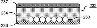
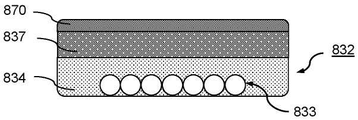
본 발명의 특정 양태에 따라, 복합 케이블은, 절연성 전도체 외피를 형성하는 전기 절연성 전도체 외피 층을 포함하고 추가적으로 지지 층, 플럭스 집중기 층 또는 차폐층 중 적어도 하나를 포함하는, 다층 복합 케이블일 수 있다. 복합 케이블의 층상 구성은, 여러 기능을 하나의 케이블에 조합할 수 있게 하고, 특히 이들 기능을 하나의 단계에서 구현할 수 있게 한다. 유리하게는, 이는 비용 및 시간 모두에서 에어로졸 발생 장치를 제조하는 데 필요한 노력을 감소시킨다.According to a particular aspect of the present invention, the composite cable may be a multilayer composite cable comprising an electrically insulating conductor sheath layer forming an insulating conductor sheath and additionally comprising at least one of a support layer, a flux concentrator layer or a shielding layer. . The layered configuration of the composite cable makes it possible to combine several functions into one cable, and in particular, to implement these functions in one step. Advantageously, this reduces the effort required to manufacture the aerosol-generating device in both cost and time.
지지 층은 주로 복합 케이블의 기계적 저항을 증가시키는 역할을 한다. 바람직하게는, 지지 층은 전기 전도체를 통해 전류에 의해 발생된 자기장의 유도 성능에 영향을 미치지 않는다. 즉, 지지 층은 바람직하게는 전자기적으로 불활성이다. 따라서, 지지 층은 바람직하게는 전자기적 불활성 재료, 특히 폴리에테르에테르케톤 또는 폴리아릴에테르케톤 중 적어도 하나를 포함한다.The support layer mainly serves to increase the mechanical resistance of the composite cable. Preferably, the support layer does not affect the ability to induce a magnetic field generated by an electric current through the electrical conductor. That is, the support layer is preferably electromagnetically inert. Accordingly, the support layer preferably comprises an electromagnetically inert material, in particular at least one of polyetheretherketone or polyaryletherketone.
지지 층은 0.1 mm 내지 1 mm, 특히 0.2 mm 내지 0.5 mm, 또는 0.25 mm 내지 1 mm, 특히 0.25 mm 내지 0.5 mm의 범위의 층 두께를 가질 수 있다. 한편, 이들 두께는 충분한 기계적 저항을 보장하기에 충분히 크다. 한편, 이들 두께는, 이러한 장치에서 제한된 설치 공간을 최적으로 사용하기 위해, 코일 권선의 반경 방향 연장부를 가능한 한 작게 유지하기에 충분히 작다.The support layer may have a layer thickness in the range from 0.1 mm to 1 mm, in particular from 0.2 mm to 0.5 mm, or from 0.25 mm to 1 mm, in particular from 0.25 mm to 0.5 mm. On the other hand, these thicknesses are large enough to ensure sufficient mechanical resistance. On the other hand, these thicknesses are small enough to keep the radial extension of the coil windings as small as possible for optimal use of the limited installation space in such devices.
지지 층은, 바람직하게는 복합 케이블이 공동 주위에 배열될 경우에, 공동을 향해 내측으로 향하는 절연성 전도체 외피 층의 일 측면 상에 배열된다.The support layer is preferably arranged on one side of the insulative conductor sheathing layer facing inwardly towards the cavity, when the composite cable is arranged around the cavity.
전기 전도체는 지지 층에 부분적으로 매립될 수 있다. 즉, 지지 층은 전기 전도체의 적어도 일부를 덮을 수 있다. 특히, 지지 층은 복합 케이블이 공동 주위에 배열될 경우에 공동을 향해 내측으로 향하는 전기 전도체의 적어도 일 측면을 덮을 수 있다.The electrical conductor may be partially embedded in the support layer. That is, the support layer may cover at least a portion of the electrical conductor. In particular, the support layer may cover at least one side of the electrical conductor facing inwardly towards the cavity when the composite cable is arranged around the cavity.
보다 더 바람직하게는, 지지 층은 에지 층, 특히 복합 케이블의 제1 측면을 형성하는 에지 층이다.Even more preferably, the support layer is an edge layer, in particular an edge layer forming the first side of the composite cable.
플럭스 집중기 층은 자기장을 왜곡시킬 수 있는 자기 플럭스 집중기로서 작용하도록 구성되고, 따라서 절연성 전도체 외피에 선택적으로 포함된 자기 플럭스 집중기 재료와 관련하여 전술한 바와 같이, 공동 내에서 유도 코일에 의해 발생된 자기장을 집중시키고 안내하도록 구성된다. 이러한 정도로, 플럭스 집중기 층은, 바람직하게는 절연성 전도체 외피에 포함된 자기 플럭스 집중기 재료 대신에 제공될 수 있다. 유리하게는, 이는, 유도 코일의 인접한 회전 사이의 단락 회로를 방지하기 위해 전체적으로 전기 절연되어야 하는 전도체 외피에서, 금속성 플럭스 집중기 재료와 같은 전기 전도성 플럭스 집중기 재료를 사용할 경우에, 가능한 문제를 피하는 데 도움이 될 수 있다. 그러나, 절연성 전도체 외피 층은, 플럭스 집중기 층 이외에 플럭스 집중기 재료를 또한 포함하는 것도 가능하다.The flux concentrator layer is configured to act as a magnetic flux concentrator capable of distorting the magnetic field, and is thus formed by an induction coil within the cavity, as described above with respect to the magnetic flux concentrator material optionally included in the insulative conductor sheath. It is configured to focus and guide the generated magnetic field. To this extent, a flux concentrator layer may be provided instead of the magnetic flux concentrator material preferably contained in the insulating conductor sheath. Advantageously, this avoids possible problems when using an electrically conductive flux concentrator material, such as a metallic flux concentrator material, in a conductor sheath that must be entirely electrically insulated to prevent short circuits between adjacent turns of the induction coil. can help However, it is also possible for the insulating conductor envelope layer to also comprise a flux concentrator material in addition to the flux concentrator layer.
자기 플럭스 집중기로서 작용하기 위해, 플럭스 집중기 층은 자기 플럭스 집중기 재료, 특히 절연성 전도체 외피와 관련하여 전술한 자기 플럭스 집중기 재료 중 임의의 하나를 포함할 수 있다. 이들 재료의 세부 사항은 여기에서 설명되었으며, 플럭스 집중기 층에 균등하게 적용된다.To act as a magnetic flux concentrator, the flux concentrator layer may comprise a magnetic flux concentrator material, particularly any one of the magnetic flux concentrator materials described above with respect to an insulating conductor sheath. The details of these materials are described here, and are equally applied to the flux concentrator layer.
플럭스 집중기 층은, 바람직하게는 복합 케이블이 공동 주위에 배열될 경우에, 공동으로부터 외측으로 등지는 절연성 전도체 외피 층의 일 측면 상에 배열된다.The flux concentrator layer is preferably arranged on one side of the insulative conductor sheath layer facing outward from the cavity when the composite cable is arranged around the cavity.
차폐 층은 차폐 층 외부의 영역에서 자기장의 악영향을 감소시키는 역할을 할 수 있고, 그 반대의 경우도 마찬가지이며, 장치의 바로 부근 또는 장치 자체의 하우징에서 전기 전도적이거나 매우 자화되기 쉬운 재료에 의한 자기장의 왜곡을 감소시키는 역할을 할 수 있다.The shielding layer can serve to reduce the adverse effects of magnetic fields in areas outside the shielding layer, and vice versa, caused by materials that are electrically conductive or highly magnetizable in the immediate vicinity of the device or in the housing of the device itself. It can serve to reduce the distortion of the magnetic field.
이를 위해, 차폐 층은 금속과 같은 전기 전도성 재료를 포함할 수 있다. 특히, 차폐 층은 알루미늄, 구리, 주석, 강, 금, 은, 전기 전도성 중합체, 페라이트 또는 이들의 임의의 조합 중 적어도 하나를 포함할 수 있다. 예를 들어, 차폐 층은, 복합 케이블이 공동 주위에 배열될 경우에, 공동으로부터 외측으로 등지는 전기 절연성 전도체 외피 층의 일 측면에 도포되는 금속 코팅일 수 있다. 금속 코팅은 임의의 적합한 방식으로, 예를 들어 금속 페인트, 금속 잉크, 또는 기상 증착 공정에 의해 도포될 수 있다.To this end, the shielding layer may comprise an electrically conductive material such as a metal. In particular, the shielding layer may comprise at least one of aluminum, copper, tin, steel, gold, silver, an electrically conductive polymer, ferrite, or any combination thereof. For example, the shielding layer may be a metallic coating applied to one side of the electrically insulating conductor sheath layer facing outward from the cavity when the composite cable is arranged around the cavity. The metallic coating may be applied in any suitable manner, for example by metallic paint, metallic ink, or vapor deposition process.
차폐 층은, 바람직하게는 복합 케이블이 공동 주위에 배열될 경우에, 공동으로부터 외측으로 등지는 절연성 전도체 외피 층의 일 측면 상에 배열된다. 바람직하게는, 차폐 층은 에지 층, 특히 복합 케이블의 제2 측면을 형성하는 에지 층일 수 있다.The shielding layer is preferably arranged on one side of the insulative conductor sheathing layer facing outward from the cavity when the composite cable is arranged around the cavity. Preferably, the shielding layer may be an edge layer, in particular an edge layer forming the second side of the composite cable.
다층 복합 케이블이 플럭스 집중기 층 및 차폐 층 둘 다를 포함하는 경우, 플럭스 집중기 층은 바람직하게는 전기 절연성 전도체 외피 층의 상단에 배열되고(바람직하게는, 복합 케이블이 공동 주위에 배열될 경우에 공동으로부터 외측으로 등지는 절연성 전도체 외피 층의 일 측면 상에 배열되고), 차폐 층은 플럭스 집중기 층의 상단에 배열되고, 바람직하게는 예컨대 에지 층이 되도록 배열되고, 특히 복합 케이블의 제2 측면을 형성하는 에지 층이 되도록 한다.If the multilayer composite cable comprises both a flux concentrator layer and a shielding layer, the flux concentrator layer is preferably arranged on top of the electrically insulating conductor sheath layer (preferably when the composite cable is arranged around the cavity). arranged on one side of the insulating conductor sheath layer facing outward from the cavity), the shielding layer is arranged on top of the flux concentrator layer, preferably arranged to be, for example, an edge layer, in particular the second side of the composite cable to be an edge layer that forms
차폐 효과를 개선하기 위해, 전기 전도성인 튜브, 슬리브, 테이프 또는 호일은 유도 코일을 추가적으로 둘러쌀 수 있다. 바람직하게는, 둘러싸는 큐브, 슬리브, 테이프 또는 호일은 유도 코일의 각 회전의 차폐 층과 물리적으로 접촉한다.To improve the shielding effectiveness, an electrically conductive tube, sleeve, tape or foil may additionally surround the induction coil. Preferably, the enclosing cube, sleeve, tape or foil is in physical contact with the shielding layer of each rotation of the induction coil.
차폐 층은 0.3 mm 내지 3 mm, 특히 0.3 mm 내지 2 mm, 또는 0.25 mm 내지 5.5 mm, 특히 0.25 mm 내지 1.75 mm의 범위의 층 두께를 가질 수 있다. 이들 두께는 코일 권선의 반경 방향 연장부를 가능한 한 작게 유지하지만, 여전히 충분한 차폐 효과를 허용하기에 매우 적합하다.The shielding layer may have a layer thickness in the range from 0.3 mm to 3 mm, in particular from 0.3 mm to 2 mm, or from 0.25 mm to 5.5 mm, in particular from 0.25 mm to 1.75 mm. These thicknesses are very suitable to keep the radial extension of the coil windings as small as possible, but still allow sufficient shielding effectiveness.
마찬가지로, 플럭스 집중기 층은 0.3 mm 내지 3 mm, 특히 0.3 mm 내지 2 mm, 또는 0.25 mm 내지 5.5 mm, 특히 0.25 mm 내지 1.75 mm의 범위의 층을 가질 수 있다.Likewise, the flux concentrator layer may have a layer in the range from 0.3 mm to 3 mm, in particular from 0.3 mm to 2 mm, or from 0.25 mm to 5.5 mm, in particular from 0.25 mm to 1.75 mm.
절연성 전도체 외피 층은 0.2 mm 내지 6 mm, 특히 0.4 mm 내지 2 mm, 또는 0.15 mm 내지 3 mm, 특히 0.3 mm 내지 1 mm, 또는 0.25 mm 내지 3 mm, 특히 0.3 mm 내지 1.5 mm, 또는 0.5 mm 내지 7 mm, 특히 0.7 mm 내지 4 mm, 또는 0.7 mm 내지 3 mm, 또는 0.4 mm 내지 9.2 mm, 특히 0.45 mm 내지 3.1 mm, 또는 0.4 mm 내지 7.2 mm, 특히 0.45 mm 내지 2.6 mm, 또는 0.45 mm 내지 3.7 mm, 특히 0.5 mm 및 2.85 mm 범위를 가질 수 있다.The insulating conductor sheath layer has a thickness of 0.2 mm to 6 mm, in particular 0.4 mm to 2 mm, or 0.15 mm to 3 mm, in particular 0.3 mm to 1 mm, or 0.25 mm to 3 mm, in particular 0.3 mm to 1.5 mm, or 0.5 mm to 7 mm, in particular 0.7 mm to 4 mm, or 0.7 mm to 3 mm, or 0.4 mm to 9.2 mm, in particular 0.45 mm to 3.1 mm, or 0.4 mm to 7.2 mm, in particular 0.45 mm to 2.6 mm, or 0.45 mm to 3.7 mm, in particular 0.5 mm and 2.85 mm.
제1 측면과 대향하는 일 측면 상에 전도체를 매립하는 절연성 전도체 외피 층의 일부는 0.2 mm 내지 7 mm, 특히 0.2 mm 내지 2 mm, 또는 0.25 mm 내지 1.5 mm, 특히 0.25 mm 내지 0.75 mm, 또는 0.2 mm 내지 5 mm, 특히 0.2 mm 내지 1.5 mm 범위의 두께를 가질 수 있다. 이들 두께는, 절연성 전도체 외피가 플럭스 집중 재료를 포함하는 경우에, 자기장의 충분한 플럭스 집중을 보장하기에 특히 적합하다.The part of the insulating conductor sheath layer which embeds the conductor on one side opposite the first side is 0.2 mm to 7 mm, in particular 0.2 mm to 2 mm, or 0.25 mm to 1.5 mm, in particular 0.25 mm to 0.75 mm, or 0.2 It may have a thickness in the range from mm to 5 mm, in particular from 0.2 mm to 1.5 mm. These thicknesses are particularly suitable to ensure sufficient flux concentration of the magnetic field when the insulating conductor sheath comprises a flux concentration material.
전도체는, 절연성 전도체 외피에 완전히 매립될 수 있다. 대안적으로, 전도체는 절연성 전도체 외피 내에, 특히 절연성 전도체 외피 층에 부분적으로 매립될 수 있고 그리고 부분적으로 지지 층에 매립될 수 있어, 예컨대 절연성 전도체 외피, 특히 절연성 전도체 외피 층 및 지지 층에 부분적으로 완전히 둘러싸일 수 있다.The conductor may be completely embedded in the insulative conductor sheath. Alternatively, the conductor may be partially embedded in the insulating conductor sheath, in particular in the insulating conductor sheath layer, and partially embedded in the supporting layer, for example partly in the insulating conductor sheath, in particular in the insulating conductor sheath layer and the supporting layer. can be completely enclosed.
에어로졸 발생 장치는 장치의 일부인 적어도 하나의 서셉터를 추가로 포함할 수 있다. 대안적으로, 적어도 하나의 서셉터는 가열될 에어로졸 형성 기재를 포함하는 에어로졸 발생 물품의 일체형 부분일 수 있다. 장치의 일부로서, 적어도 하나의 서셉터는 예컨대 사용 동안 에어로졸 형성 기재와 열적으로 근접하거나 열 접촉, 바람직하게는 물리적으로 접촉하도록 공동 내에 적어도 부분적으로 배열되거나 배열 가능하다.The aerosol-generating device may further comprise at least one susceptor that is part of the device. Alternatively, the at least one susceptor may be an integral part of the aerosol-generating article comprising the aerosol-forming substrate to be heated. As part of the device, the at least one susceptor is arranged or arrangeable at least partially within the cavity, for example in thermal proximity or thermal contact, preferably physical contact, with the aerosol-forming substrate during use.
서셉터는 에어로졸 형성 기재로부터 에어로졸을 생성하기에 충분한 온도까지 유도 가열될 수 있는 임의의 재료로 형성될 수 있다. 바람직한 서셉터는 금속 또는 탄소를 포함하고 있다. 바람직한 서셉터는 강자성 재료, 예를 들어 페라이트 철, 또는 강자성 철 또는 스테인리스강을 포함할 수 있다. 적합한 서셉터는 알루미늄이거나 이를 포함할 수 있다. 바람직한 서셉터는 400 시리즈 스테인레스 강, 예를 들어 410등급, 또는 420등급 또는 430등급 스테인리스 강으로 형성될 수 있다.The susceptor may be formed of any material that can be inductively heated to a temperature sufficient to generate an aerosol from the aerosol-forming substrate. Preferred susceptors contain metal or carbon. A preferred susceptor may comprise a ferromagnetic material, for example ferritic iron, or ferromagnetic iron or stainless steel. A suitable susceptor may be or include aluminum. Preferred susceptors may be formed from 400 series stainless steel, for example grade 410, or grade 420 or grade 430 stainless steel.
서셉터는 다양한 기하학적 구성을 포함할 수 있다. 서셉터는 서셉터 핀, 서셉터 로드, 서셉터 블레이드, 서셉터 스트립 또는 서셉터 플레이트를 포함할 수 있거나 이들일 수 있다. 서셉터가 에어로졸 발생 장치의 일부인 경우, 서셉터 핀, 서셉터 핀, 서셉터 로드, 서셉터 블레이드, 서셉터 스트립 또는 서셉터 플레이트는 장치의 공동 내로, 바람직하게는 공동 내로 에어로졸 발생 물품을 삽입하기 위해 사용되는 공동의 개구를 향해 돌출할 수 있다.The susceptor may include a variety of geometric configurations. The susceptor may include or may include a susceptor pin, a susceptor rod, a susceptor blade, a susceptor strip, or a susceptor plate. When the susceptor is part of an aerosol-generating device, a susceptor pin, susceptor pin, susceptor rod, susceptor blade, susceptor strip or susceptor plate is used to insert the aerosol-generating article into the cavity of the device, preferably into the cavity. may protrude towards the opening of the cavity used for
서셉터는 필라멘트 서셉터, 메쉬 서셉터, 심지 서셉터를 포함할 수 있거나 이들일 수 있다.The susceptor may include or may be a filament susceptor, a mesh susceptor, or a wick susceptor.
마찬가지로, 서셉터는 서셉터 슬리브, 서셉터 컵, 원통형 서셉터 또는 관형 서셉터를 포함할 수 있거나 이들일 수 있다. 바람직하게는, 서셉터 슬리브, 서셉터 컵, 원통형 서셉터 또는 관형 서셉터의 내부 공극은 에어로졸 발생 물품의 적어도 일부를 제거 가능하게 수용하도록 구성된다.Likewise, the susceptor may comprise or may be a susceptor sleeve, a susceptor cup, a cylindrical susceptor or a tubular susceptor. Preferably, the interior void of the susceptor sleeve, susceptor cup, cylindrical susceptor or tubular susceptor is configured to removably receive at least a portion of the aerosol-generating article.
전술한 서셉터는 임의의 단면 형상, 예를 들어 원형, 타원형, 정사각형, 직사각형, 삼각형 또는 임의의 다른 적합한 형상을 가질 수 있다.The aforementioned susceptors may have any cross-sectional shape, for example circular, oval, square, rectangular, triangular or any other suitable shape.
유도 코일에 더하여, 유도 가열 배열부는 교류(AC) 발전기를 포함할 수 있다. AC 발전기는 에어로졸 발생 장치의 전력 공급부에 의해 전력을 공급받을 수 있다. AC 발전기는 적어도 하나의 유도 코일에 작동 가능하게 결합된다. 특히, 적어도 하나의 유도 코일은 AC 발전기의 일체형 부분일 수 있다. AC 발생기는 교류 전자기장을 발생시키기 위해 유도 코일을 통과하는 고주파 발진 전류를 발생시키도록 구성되어 있다. AC 전류는 시스템의 활성화 후 연속적으로 유도 코일에 공급될 수 있거나 간헐적으로, 예컨대 퍼핑할 때마다 공급될 수 있다.In addition to the induction coil, the induction heating arrangement may include an alternating current (AC) generator. The AC generator may be powered by a power supply of the aerosol-generating device. The AC generator is operatively coupled to the at least one induction coil. In particular, the at least one induction coil may be an integral part of the AC generator. The AC generator is configured to generate a high frequency oscillating current that passes through an induction coil to generate an alternating electromagnetic field. AC current may be supplied to the induction coil continuously after activation of the system or may be supplied intermittently, eg with each puff.
바람직하게는, 유도 가열 배열부는 LC 네트워크를 포함하는 DC 전력 공급부에 연결된 DC/AC 변환기를 포함하며, LC 네트워크는 커패시터 및 유도 코일의 직렬 연결을 포함한다.Preferably, the induction heating arrangement comprises a DC/AC converter connected to a DC power supply comprising an LC network, the LC network comprising a series connection of a capacitor and an induction coil.
유도 가열 배열부는, 바람직하게는 고주파 전자기장을 발생시키도록 구성되어 있다. 본원에서 지칭되는 바와 같이, 고주파 전자기장은 500 kHz(킬로헤르츠) 내지 30 MHz(메가헤르츠), 특히 5 MHz(메가헤르츠) 내지 15 MHz(메가헤르츠), 바람직하게는 5 MHz(메가헤르츠) 내지 10 MHz(메가헤르츠)의 범위 내에 있을 수 있다.The induction heating arrangement is preferably configured to generate a high-frequency electromagnetic field. As referred to herein, high-frequency electromagnetic fields are from 500 kHz (kilohertz) to 30 MHz (megahertz), in particular from 5 MHz (megahertz) to 15 MHz (megahertz), preferably from 5 MHz (megahertz) to 10 It can be in the range of megahertz (MHz).
에어로졸 발생 장치는 장치의 작동을 제어하도록 구성된 컨트롤러를 더 포함할 수 있다. 특히, 컨트롤러는 에어로졸 형성 기재의 가열을 미리 결정된 작동 온도로 제어하기 위해, 바람직하게는 폐쇄 루프 구성에서 유도 가열 배열부의 작동을 제어하도록 구성될 수 있다. 에어로졸 형성 기재를 가열하기 위해 사용되는 작동 온도는 적어도 180℃, 특히 적어도 300℃, 특히 적어도 350℃, 바람직하게는 적어도 370℃, 가장 바람직하게는 적어도 400℃일 수 있다. 이러한 온도는 에어로졸 형성 기재를 가열하지만 연소하지 않기 위한 통상적인 작동 온도이다. 바람직하게, 작동 온도는 180℃ 내지 370℃, 특히 180℃ 내지 240℃ 또는 280℃ 내지 370℃의 범위이다. 일반적으로, 작동 온도는 가열될 에어로졸 형성 기재의 유형, 서셉터의 구성 및 시스템의 사용 시 에어로졸 형성 기재에 대한 서셉터의 배열 중 적어도 하나에 의존할 수 있다. 예를 들어, 서셉터가 예컨대 시스템의 사용 시 에어로졸 형성 기재를 둘러싸도록 구성되고 배열되는 경우, 작동 온도는 180℃ 내지 240℃의 범위일 수 있다. 마찬가지로, 서셉터가 예컨대 시스템의 사용 시 에어로졸 형성 기재 내에 배열되도록 구성되는 경우, 작동 온도는 280℃ 내지 370℃의 범위일 수 있다. 전술한 바와 같은 작동 온도는, 바람직하게는 서셉터의 사용 시 온도를 지칭한다.The aerosol-generating device may further comprise a controller configured to control operation of the device. In particular, the controller may be configured to control the heating of the aerosol-forming substrate to a predetermined operating temperature, preferably to control the operation of the induction heating arrangement in a closed loop configuration. The operating temperature used to heat the aerosol-forming substrate may be at least 180°C, in particular at least 300°C, in particular at least 350°C, preferably at least 370°C, most preferably at least 400°C. This temperature is a typical operating temperature for heating but not burning the aerosol-forming substrate. Preferably, the operating temperature ranges from 180°C to 370°C, in particular from 180°C to 240°C or from 280°C to 370°C. In general, the operating temperature may depend on at least one of the type of aerosol-forming substrate to be heated, the configuration of the susceptor, and the arrangement of the susceptor relative to the aerosol-forming substrate in use of the system. For example, where the susceptor is constructed and arranged to surround an aerosol-forming substrate, such as in use of the system, the operating temperature may range from 180°C to 240°C. Likewise, when the susceptor is configured to be arranged within, for example, an aerosol-forming substrate in use of the system, the operating temperature may range from 280°C to 370°C. Operating temperature, as described above, preferably refers to the temperature at the time of use of the susceptor.
컨트롤러는 마이크로프로세서, 예를 들어 프로그래밍 가능 마이크로프로세서, 마이크로컨트롤러, 또는 주문형 반도체(ASIC) 또는 제어를 제공할 수 있는 다른 전자 회로를 포함할 수 있다. 컨트롤러는 적어도 하나의 DC/AC 인버터 및/또는 전력 증폭기, 예를 들어 클래스-C, 클래스-D, 또는 클래스-E 전력 증폭기와 같은 추가 전자 부품을 포함할 수 있다. 특히, 유도 가열 배열부는 컨트롤러의 일부일 수 있다.The controller may include a microprocessor, such as a programmable microprocessor, microcontroller, or application specific integrated circuit (ASIC) or other electronic circuit capable of providing control. The controller may include at least one DC/AC inverter and/or additional electronic components such as a power amplifier, for example a class-C, class-D, or class-E power amplifier. In particular, the induction heating arrangement may be part of the controller.
에어로졸 발생 장치는 전력 공급부, 특히 DC 공급 전압 및 DC 공급 전류를 유도 가열 배열부에 제공하도록 구성된 DC 전력 공급부를 포함할 수 있다. 바람직하게는, 전력 공급부는 리튬 철 인산염 배터리와 같은 배터리이다. 대안으로서, 전력 공급부는 커패시터와 같은 전하 저장 장치의 다른 형태일 수 있다. 전력 공급부는 재충전을 필요할 수 있으며, 즉 전력 공급부는 재충전 가능할 수 있다. 전력 공급부는 하나 이상의 사용자 경험을 위해 충분한 에너지의 저장을 허용하는 용량을 가질 수 있다. 예를 들어, 전력 공급부는 약 6분의 기간 동안, 또는 6분의 여러 배의 기간 동안 연속적으로 에어로졸을 발생시키기에 충분한 용량을 가질 수 있다. 다른 예에서, 전력 공급부는 미리 결정된 수의 퍼프, 또는 유도 가열 배열의 개별적인 활성화를 허용하는 데 충분한 용량을 가질 수 있다.The aerosol-generating device may comprise a power supply, in particular a DC power supply configured to provide a DC supply voltage and a DC supply current to the induction heating arrangement. Preferably, the power supply is a battery, such as a lithium iron phosphate battery. Alternatively, the power supply may be another form of electrical charge storage device such as a capacitor. The power supply may need to be recharged, ie the power supply may be rechargeable. The power supply may have a capacity to allow storage of sufficient energy for one or more user experiences. For example, the power supply may have sufficient capacity to continuously generate the aerosol for a period of about six minutes, or several times six minutes. In another example, the power supply may have a sufficient capacity to permit individual activation of a predetermined number of puffs, or induction heating arrangements.
에어로졸 발생 장치는, 바람직하게는 유도 가열 배열부, 특히 적어도 하나의 유도 코일, 컨트롤러, 전력 공급부 및 공동의 적어도 일부 중 적어도 하나를 포함하는 본체를 포함할 수 있다.The aerosol-generating device may preferably comprise an induction heating arrangement, in particular a body comprising at least one of at least one induction coil, a controller, a power supply and at least a part of the cavity.
본체에 더하여, 에어로졸 발생 장치는, 특히 장치와 함께 사용될 에어로졸 발생 물품이 마우스피스를 포함하지 않는 경우에, 마우스피스를 더 포함할 수 있다. 마우스피스는 장치의 본체에 장착될 수 있다. 마우스피스는 마우스피스를 본체에 장착할 때 공동을 폐쇄하도록 구성될 수 있다. 본체에 마우스피스를 부착하기 위해, 본체의 근위 말단부는, 마우스피스의 원위 말단부에서 대응 부분과 맞물리는, 자석 또는 기계적 장착, 예를 들어 베이오넷 마운트 또는 스냅핏(snap-fit) 장착부를 포함할 수 있다. 장치가 마우스피스를 포함하지 않는 경우에, 에어로졸 발생 장치와 함께 사용될 에어로졸 발생 물품은 마우스피스, 예를 들어 필터 플러그를 포함할 수 있다.In addition to the body, the aerosol-generating device may further comprise a mouthpiece, particularly where the aerosol-generating article to be used with the device does not comprise a mouthpiece. The mouthpiece may be mounted to the body of the device. The mouthpiece may be configured to close the cavity when the mouthpiece is mounted to the body. To attach the mouthpiece to the body, the proximal end of the body may include a magnetic or mechanical mount, such as a bayonet mount or snap-fit mount, that engages a mating portion at the distal end of the mouthpiece. can Where the device does not include a mouthpiece, the aerosol-generating article to be used with the aerosol-generating device may include a mouthpiece, for example a filter plug.
에어로졸 발생 장치는 적어도 하나의 공기 배출구, 예를 들어(존재하는 경우) 마우스피스 내에 공기 배출구를 포함할 수 있다.The aerosol-generating device may comprise at least one air outlet, for example (if present) an air outlet in the mouthpiece.
바람직하게는, 에어로졸 발생 장치는 적어도 하나의 공기 유입구로부터 공동을 통해, 가능하게는 추가로, 존재하는 경우, 마우스피스 내의 공기 배출구로 연장되는 공기 경로를 포함한다. 바람직하게는, 에어로졸 발생 장치는 공동과 유체 연통하는 적어도 하나의 공기 유입구를 포함한다. 따라서, 에어로졸 발생 시스템은 적어도 하나의 공기 유입구로부터 공동으로, 그리고 가능하게는 추가로 물품 및 마우스피스 내의 에어로졸 형성 기재를 통해 사용자의 입 속으로 연장되는 공기 경로를 포함할 수 있다.Preferably, the aerosol-generating device comprises an air path extending from the at least one air inlet through the cavity, possibly further, if present, to an air outlet in the mouthpiece. Preferably, the aerosol-generating device comprises at least one air inlet in fluid communication with the cavity. Accordingly, the aerosol-generating system may comprise an air path extending from the at least one air inlet to the cavity and possibly further through the article and the aerosol-forming substrate in the mouthpiece into the mouth of the user.
본 발명의 다른 양태에 따라, 장치는 공동의 적어도 일부를 정의하는 유도 모듈을 포함할 수 있다. 유도 코일은 유도 모듈의 내부 표면에 배열될 수 있다. 대안적으로, 유도 코일은 유도 모듈의 외부 표면에 배열될 수 있다. 특히, 유도 코일은 유도 모듈의 내부 또는 외부 표면에서 오목부, 예를 들어 환형 오목부 내에 배열될 수 있다.According to another aspect of the invention, an apparatus may comprise an induction module defining at least a portion of the cavity. The induction coil may be arranged on the inner surface of the induction module. Alternatively, the induction coil may be arranged on the outer surface of the induction module. In particular, the induction coil may be arranged in a recess, for example an annular recess, in the inner or outer surface of the induction module.
유도 모듈은 슬리브 형상의 유도 모듈, 특히 원통형 공동을 정의하기 위한 원통형 유도 모듈일 수 있다. 바람직하게는, 유도 모듈은 장치 하우징 내에 배열되고, 특히 제거 가능하게 배열된다.The induction module may be a sleeve-shaped induction module, in particular a cylindrical induction module for defining a cylindrical cavity. Preferably, the induction module is arranged in the device housing, in particular is arranged removably.
이와 같이, 본 발명은 또한 예컨대 장치의 공동의 적어도 일부를 형성하거나 적어도 일부 주위에 원주 방향으로 배열되도록 에어로졸 발생 장치 내에 배열 가능한 유도 모듈을 제공하며, 공동은 유도 가열될 에어로졸 형성 기재를 제거 가능하게 수용하도록 구성된다. 유도 모듈은 사용 시 공동 내에 교번 전자기장을 발생시키기 위한 적어도 하나의 유도 코일을 포함하며, 적어도 하나의 유도 코일은 유도 모듈이 장치 내에 배열될 경우에 공동의 적어도 일부 주위에 배열된다. 유도 코일은 공동의 적어도 일부분 주위에 배열된 복합 케이블의 복수의 회전에 의해 형성되며, 복합 케이블은 절연성 전도체 외피에 적어도 부분적으로 매립된 전기 전도체를 포함하고, 전도체는 서로 전기적으로 접촉하는 복수의 비절연성 와이어를 포함한다.As such, the present invention also provides an induction module arrangable within an aerosol-generating device, such as to form at least a portion of or arranged circumferentially around at least a portion of a cavity of the device, the cavity being capable of removing the aerosol-forming substrate to be inductively heated configured to accommodate. The induction module comprises at least one induction coil for generating an alternating electromagnetic field in the cavity in use, the at least one induction coil being arranged around at least a portion of the cavity when the induction module is arranged in the device. The induction coil is formed by a plurality of turns of a composite cable arranged around at least a portion of the cavity, the composite cable comprising an electrical conductor at least partially embedded in an insulative conductor sheath, the conductors being in electrical contact with each other insulated wire.
유도 모듈, 특히 유도 코일 및 복합체 케이블의 추가 특징 및 장점은 에어로졸 발생 장치에 대해 설명되었고 반복되지 않을 것이다.Additional features and advantages of induction modules, in particular induction coils and composite cables, have been described for aerosol-generating devices and will not be repeated.
본 발명에 따르면, 본 발명에 따른 그리고 본원에 설명된 바와 같은 에어로졸 발생 장치를 포함하는 에어로졸 발생 시스템이 또한 제공된다. 시스템은 장치와 함께 사용하기 위한 에어로졸 발생 물품을 더 포함하며, 물품은 장치에 의해 유도 가열될 에어로졸 형성 기재를 포함한다. 에어로졸 발생 물품은 장치의 공동 내에 적어도 부분적으로 수용되거나 수용 가능할 수 있다.According to the invention, there is also provided an aerosol-generating system comprising an aerosol-generating device according to the invention and as described herein. The system further comprises an aerosol-generating article for use with the device, the article comprising an aerosol-forming substrate to be inductively heated by the device. The aerosol-generating article may be received or receivable at least partially within the cavity of the device.
전에 언급된 바와 같이, 에어로졸 형성 기재를 유도 가열하기 위해 사용되는 적어도 하나의 서셉터는 에어로졸 발생 장치 대신, 에어로졸 발생 물품의 일체형 부분일 수 있다. 따라서, 에어로졸 발생 물품은, 물품이 장치의 공동 내에 수용될 경우에 사용 시 서셉터가 유도 가열 배열부에 의해 유도 가열 가능하도록 에어로졸 형성 기재와 열적으로 근접하거나 열적으로 접촉하여 위치한 적어도 하나의 서셉터를 포함할 수 있다.As mentioned before, the at least one susceptor used for inductively heating the aerosol-forming substrate may be an integral part of the aerosol-generating article, instead of an aerosol-generating device. Accordingly, the aerosol-generating article comprises at least one susceptor positioned in thermal proximity or thermal contact with the aerosol-forming substrate such that the susceptor is capable of induction heating by the induction heating arrangement in use when the article is received within a cavity of the device. may include
본 발명에 따른 에어로졸 발생 시스템의 추가 특징 및 장점은 에어로졸 발생 장치에 관해 설명되었고 반복되지 않을 것이다.Further features and advantages of the aerosol-generating system according to the invention have been described with respect to an aerosol-generating device and will not be repeated.
본원에서 사용되는 바와 같이, 용어 “에어로졸 발생 장치”는 일반적으로 예컨대 기재를 가열함으로써 에어로졸을 발생시키기 위해, 적어도 하나의 에어로졸 형성 기재, 특히 에어로졸 발생 물품 내에 제공되는 에어로졸 형성 기재와 상호작용할 수 있는 전기 작동식 장치를 지칭한다. 바람직하게는, 에어로졸 발생 장치는 사용자의 입을 통해 사용자가 직접 흡입할 수 있는 에어로졸을 발생시키기 위한 퍼핑 장치이다. 특히, 에어로졸 발생 장치는 핸드헬드 에어로졸 발생 장치이다.As used herein, the term “aerosol-generating device” generally refers to electricity capable of interacting with at least one aerosol-forming substrate, particularly an aerosol-forming substrate provided within an aerosol-generating article, to generate an aerosol, such as by heating the substrate. It refers to an actuated device. Preferably, the aerosol-generating device is a puffing device for generating an aerosol that can be directly inhaled by the user through the user's mouth. In particular, the aerosol-generating device is a handheld aerosol-generating device.
본원에서 사용되는 바와 같이, 용어 "서셉터"는 교번 자기장을 받을 때 전자기 에너지를 열로 변환할 수 있는 요소를 지칭한다. 이는 서셉터 재료의 전기 및 자기 특성에 따라, 서셉터에 유도된 히스테리시스 손실 및/또는 와전류의 결과일 수 있다. 히스테리시스 손실은 교번 전자기장의 영향 하에 스위칭되는 재료 내의 자기 도메인으로 인해 강자성 또는 페리자성 서셉터에서 발생한다. 와전류는 서셉터가 전기 전도성인 경우에 유도될 수 있다. 전기 전도성 강자성 또는 페리자성 서셉터의 경우, 와전류 및 히스테리시스 손실 둘 모두로 인해 열이 발생될 수 있다.As used herein, the term “susceptor” refers to an element capable of converting electromagnetic energy into heat when subjected to an alternating magnetic field. This may be the result of hysteresis losses and/or eddy currents induced in the susceptor, depending on the electrical and magnetic properties of the susceptor material. Hysteresis losses occur in ferromagnetic or ferrimagnetic susceptors due to the magnetic domains in the material being switched under the influence of alternating electromagnetic fields. Eddy currents can be induced if the susceptor is electrically conductive. In the case of electrically conductive ferromagnetic or ferrimagnetic susceptors, heat can be generated due to both eddy currents and hysteresis losses.
본원에서 사용되는 바와 같이, 용어 “에어로졸 발생 물품”은, 가열될 때, 에어로졸을 형성할 수 있는 휘발성 화합물을 방출하는 적어도 하나의 에어로졸 형성 기재를 포함한 물품을 지칭한다. 바람직하게는, 에어로졸 발생 물품은 가열식 에어로졸 발생 물품이다. 즉, 에어로졸 발생 물품은 에어로졸을 형성할 수 있는 휘발성 화합물을 방출하기 위해 연소되는 것이 아니라 가열되도록 의도되는 적어도 하나의 에어로졸 형성 기재를 포함한다. 에어로졸 발생 물품은 소모품, 특히 단일 사용 후에 폐기될 소모품일 수 있다. 예를 들어, 물품은 가열될 액체 에어로졸 형성 기재를 포함하고 있는 카트리지일 수 있다. 대안적으로는, 물품은 로드 형상 물품, 종래의 궐련을 닮은, 특히 담배 물품일 수 있다. 전술한 바와 같이, 물품은, 물품이 장치의 공동 내에 수용될 경우에 사용 시 서셉터가 유도 가열 배열부에 의해 유도 가열 가능하도록 에어로졸 형성 기재와 열적으로 근접하거나 열적으로 접촉하여 위치한 적어도 하나의 서셉터를 추가로 포함할 수 있다.As used herein, the term “aerosol-generating article” refers to an article comprising at least one aerosol-forming substrate that, when heated, releases a volatile compound capable of forming an aerosol. Preferably, the aerosol-generating article is a heated aerosol-generating article. That is, the aerosol-generating article comprises at least one aerosol-forming substrate which is intended to be heated rather than combusted to release volatile compounds capable of forming an aerosol. The aerosol-generating article may be a consumable, particularly a consumable to be discarded after a single use. For example, the article may be a cartridge containing a liquid aerosol-forming substrate to be heated. Alternatively, the article may be a rod-shaped article, resembling a conventional cigarette, in particular a tobacco article. As noted above, the article comprises at least one susceptor positioned in thermal proximity or thermal contact with the aerosol-forming substrate such that the susceptor is capable of induction heating by the induction heating arrangement in use when the article is received within a cavity of the device. It may further include a scepter.
본원에서 사용되는 바와 같이, 용어 “에어로졸 형성 기재”는 에어로졸을 발생시키기 위해 가열 시 휘발성 화합물을 방출할 수 있는 에어로졸 형성 재료를 포함하거나 그로 형성된 기재를 나타낸다. 에어로졸 형성 기재는 에어로졸 형성 휘발성 화합물을 방출하기 위해 연소되기보다는 가열되도록 의도된다. 에어로졸 형성 기재는 고체 에어로졸 형성 기재 또는 액체 에어로졸 형성 기재 또는 겔 유사 에어로졸 형성 기재, 또는 이들의 임의의 조합일 수 있다. 즉, 에어로졸 형성 기재는, 예를 들어 고체 및 액체 성분 모두를 포함할 수 있다. 에어로졸 형성 기재는 가열 시에 기재로부터 방출되는 휘발성 담배 향미 화합물을 함유하는 담배 함유 재료를 포함할 수 있다. 대안적으로 또는 추가적으로, 에어로졸 형성 기재는 비-담배 재료를 포함할 수 있다. 에어로졸 형성 기재는 에어로졸 형성제를 더 포함할 수 있다. 적합한 에어로졸 형성제의 예는 글리세린 및 프로필렌 글리콜이다. 에어로졸 형성 기재는 또한 니코틴 또는 향미제와 같은 다른 첨가제 및 성분을 포함할 수 있다. 에어로졸 형성 기재는 또한 페이스트형 재료, 에어로졸 형성 기재를 포함하고 있는 다공성 재료의 향낭, 또는, 예를 들어 글리세린과 같은 일반적인 에어로졸 형성제를 포함할 수 있는, 겔화제 또는 점착제와 혼합된, 이후 플러그로 압축 또는 몰딩되는 말아피는 담배(loose tobacco)일 수 있다.As used herein, the term “aerosol-forming substrate” refers to a substrate comprising or formed from an aerosol-forming material capable of releasing volatile compounds upon heating to generate an aerosol. The aerosol-forming substrate is intended to be heated rather than combusted to release the aerosol-forming volatile compound. The aerosol-forming substrate may be a solid aerosol-forming substrate or a liquid aerosol-forming substrate or a gel-like aerosol-forming substrate, or any combination thereof. That is, the aerosol-forming substrate may include, for example, both solid and liquid components. The aerosol-forming substrate may comprise a tobacco-containing material containing a volatile tobacco flavor compound that is released from the substrate upon heating. Alternatively or additionally, the aerosol-forming substrate may comprise a non-tobacco material. The aerosol-forming substrate may further comprise an aerosol former. Examples of suitable aerosol formers are glycerin and propylene glycol. The aerosol-forming substrate may also include other additives and ingredients such as nicotine or flavoring agents. The aerosol-forming substrate may also be a paste-like material, a sachet of porous material containing the aerosol-forming substrate, or mixed with a gelling agent or tackifier, which may contain a common aerosol former, for example glycerin, then plugged into a plug. It may be loose tobacco that is compressed or molded.
본원에서 사용되는 바와 같이, 용어 "에어로졸 발생 시스템"은 본 발명에 따른 그리고 본원에 설명된 바와 같은 에어로졸 발생 장치와 함께 본원에 추가로 설명된 바와 같은 에어로졸 발생 물품의 조합을 지칭한다. 시스템에 있어서, 물품 및 장치는 협력하여 호흡성 에어로졸을 발생시킨다.As used herein, the term “aerosol-generating system” refers to a combination of an aerosol-generating article as further described herein with an aerosol-generating device according to the invention and as described herein. In the system, the article and device cooperate to generate a respiratory aerosol.
아래에 비제한적인 실시예의 비-포괄적인 목록이 제공되어 있다. 이들 실시예의 임의의 하나 이상의 특징부는 본원에 설명된 다른 실시예, 구현예, 또는 양태의 임의의 하나 이상의 특징부와 조합될 수 있다.A non-exhaustive list of non-limiting examples is provided below. Any one or more features of these embodiments may be combined with any one or more features of other embodiments, implementations, or aspects described herein.
실시예 1: 에어로졸 형성 기재를 유도 가열하여 에어로졸을 발생시키기 위한 에어로졸 발생 장치로, 상기 장치는,Example 1: An aerosol-generating device for generating an aerosol by induction heating an aerosol-forming substrate, the device comprising:
가열될 에어로졸 형성 기재의 적어도 일부를 제거 가능하게 수용하도록 구성된 공동을 포함하는 장치 하우징;a device housing comprising a cavity configured to removably receive at least a portion of the aerosol-forming substrate to be heated;
상기 공동 내에 교번 자기장을 생성하기 위한 유도 코일을 포함하는 유도 가열 배열부를 포함하되, 상기 유도 코일은 상기 공동의 적어도 일부분 주위에 배열된 복합 케이블의 복수의 회전에 의해 형성되며, 상기 복합 케이블은 절연성 전도체 외피에 적어도 부분적으로 매립된 전기 전도체를 포함하며, 상기 전도체는 서로 전기적으로 접촉하는 복수의 비절연 와이어를 포함하는, 에어로졸 발생 장치.an induction heating arrangement comprising an induction coil for generating an alternating magnetic field within the cavity, wherein the induction coil is formed by a plurality of turns of a composite cable arranged around at least a portion of the cavity, the composite cable being insulative An aerosol-generating device comprising an electrical conductor at least partially embedded in a conductor sheath, said conductor comprising a plurality of uninsulated wires in electrical contact with each other.
실시예 2: 실시예 1에 있어서, 상기 와이어는 상기 복합 케이블의 길이 연장부를 따라 서로 평행하게 이어지는, 에어로졸 발생 장치.Embodiment 2: The aerosol-generating device of embodiment 1, wherein the wires run parallel to each other along the length extension of the composite cable.
실시예 3: 실시예 1 또는 실시예 2에 있어서, 상기 와이어는 단일 층에서 상기 복합 케이블의 길이 연장부를 따라 서로 평행하게 이어지는, 에어로졸 발생 장치.Embodiment 3: The aerosol-generating device according to embodiment 1 or 2, wherein the wires run parallel to each other along the length extension of the composite cable in a single layer.
실시예 4: 실시예 1 또는 실시예 2에 있어서, 상기 와이어는, 서로의 상단 상의 복수의 층에서, 특히 서로의 상단 상의 2, 3, 또는 4층에서, 상기 복합 케이블의 길이 연장부를 따라 서로 평항하게 이어지는, 에어로졸 발생 장치.Embodiment 4: The wire according to embodiment 1 or 2, wherein the wires are connected to each other along the length extension of the composite cable in a plurality of layers on top of each other, particularly in layers 2, 3 or 4 on top of each other. A smooth running, aerosol-generating device.
실시예 5: 실시예 4에 있어서, 각각의 층의 와이어의 적어도 일부는 인접한 층의 와이어 사이에 형성된 홈 내에 배열되는, 에어로졸 발생 장치.Embodiment 5: The aerosol-generating device according to embodiment 4, wherein at least a portion of the wires of each layer are arranged in a groove formed between the wires of an adjacent layer.
실시예 6: 실시예 3 내지 실시예 5 중 어느 한 예에 있어서, 상기 단일 층 또는 상기 복수의 층 각각은 편평한 층인, 에어로졸 발생 장치.Embodiment 6: The aerosol-generating device according to any of embodiments 3-5, wherein each of the single layer or the plurality of layers is a flat layer.
실시예 7: 실시예 3 내지 실시예 5 중 어느 한 예에 있어서, 상기 단일 층 또는 상기 복수의 층 각각은 만곡형 층인, 에어로졸 발생 장치.Example 7: The aerosol-generating device according to any of embodiments 3-5, wherein each of the single layer or the plurality of layers is a curved layer.
실시예 8: 실시예 3 내지 실시예 7 중 어느 한 예에 있어서, 상기 단일 층 또는 상기 복수의 층 중 각각의 하나는 상기 복합 케이블의 복수의 회전에 의해 정의되는 원주면에 평행한, 에어로졸 발생 장치.Embodiment 8: the aerosol generating of any of embodiments 3-7, wherein each one of the single layer or the plurality of layers is parallel to a circumferential surface defined by a plurality of turns of the composite cable Device.
실시예 9: 실시예 1 내지 실시예 8 중 어느 한 예에 있어서, 상기 복수의 와이어 중 각각의 와이어는 원형 외부 단면 또는 타원형 외부 단면 또는 계란형 외부 단면 또는 직사각형 외부 단면 또는 정사각형 외부 단면을 갖는, 에어로졸 발생 장치.Embodiment 9: The aerosol of any of embodiments 1-8, wherein each wire of the plurality of wires has a circular outer cross-section or an elliptical outer cross-section or an oval outer cross-section or a rectangular outer cross-section or a square outer cross-section generating device.
실시예 10: 실시예 1 내지 실시예 9 중 어느 한 예에 있어서, 상기 복수의 와이어 중 각각의 와이어는 0.2 mm 내지 2.3 mm, 특히 0.25 mm 내지 1.2 mm, 또는 0.15 mm 내지 1.5 mm, 특히 0.25 mm 내지 0.75 mm 범위의 직경을 갖는, 에어로졸 발생 장치.Embodiment 10: The method according to any one of embodiments 1 to 9, wherein each wire of the plurality of wires is between 0.2 mm and 2.3 mm, in particular between 0.25 mm and 1.2 mm, or between 0.15 mm and 1.5 mm, in particular 0.25 mm an aerosol-generating device having a diameter in the range of from to 0.75 mm.
실시예 11: 실시예 1 내지 실시예 10 중 어느 한 예에 있어서, 상기 복수의 와이어 중 각각의 와이어는 0.1 mm2 내지 17 mm2, 특히 0.2 mm2 내지 4.5 mm2, 또는 0.07 mm2 내지 7 mm2, 특히 0.2 mm2 내지 1.8 mm2 범위의 단면적을 갖는, 에어로졸 발생 장치.Embodiment 11: The method according to any one of embodiments 1 to 10, wherein each wire of the plurality of wires is from 0.1 mm 2 to 17 mm 2 , in particular from 0.2 mm 2 to 4.5 mm 2 , or from 0.07 mm 2 to 7 mm 2 , in particular having a cross-sectional area in the range from 0.2 mm 2 to 1.8 mm 2 .
실시예 12: 실시예 1 내지 실시예 11 중 어느 한 예에 있어서, 상기 복합 케이블은 편평한 복합 케이블인, 에어로졸 발생 장치.Embodiment 12: The aerosol-generating device according to any of embodiments 1-11, wherein the composite cable is a flat composite cable.
실시예 13: 실시예 1 내지 실시예 12 중 어느 한 예에 있어서, 상기 복합 케이블은 원형 단면을 갖는, 에어로졸 발생 장치.Embodiment 13: The aerosol-generating device of any of embodiments 1-12, wherein the composite cable has a circular cross-section.
실시예 14: 실시예 1 내지 실시예 12 중 어느 한 예에 있어서, 상기 복합 케이블은 비-원형 외부 단면, 특히 실질적으로 직사각형의 외부 단면 또는 실질적으로 정사각형의 외부 단면 또는 실질적으로 타원형의 외부 단면 또는 실질적으로 계란형의 외부 단면 또는 실질적으로 외부 평행사변형 형상의 단면 또는 실질적으로 사다리꼴의 외부 단면 또는 실질적으로 아크 형상의 외부 단면을 갖는, 에어로졸 발생 장치.Embodiment 14: The composite cable according to any one of embodiments 1 to 12, wherein the composite cable has a non-circular outer cross-section, in particular a substantially rectangular outer cross-section or a substantially square outer cross-section or a substantially oval outer cross-section or An aerosol-generating device having a substantially oval outer cross-section or a substantially outer parallelogram-shaped cross-section or a substantially trapezoidal outer cross-section or a substantially arc-shaped outer cross-section.
실시예 15: 실시예 1 내지 실시예 14 중 어느 한 예에 있어서, 상기 복합 케이블은 - 공동 주위에 배열될 시 - 공동을 향해 내측으로 향하는 제1 측면 및 공동으로부터 외측으로 등지고 상기 제1 측면에 대향하는 제2 측면을 포함하는, 에어로졸 발생 장치.Embodiment 15: The composite cable according to any of embodiments 1-14, wherein the composite cable - when arranged around the cavity - has a first side facing inward towards the cavity and outwardly from the cavity and facing the first side. an aerosol-generating device comprising an opposing second side.
실시예 16: 실시예 1 내지 실시예 15 중 어느 한 예에 있어서, 상기 복합 케이블의 외부 단면, 특히 비-원형 외부 단면은 제1 대칭 축, 특히 상기 제1 측면과 상기 제2 측면 사이에서 연장되거나 상기 복합 케이블의 복수의 회전에 대해 반경 방향으로 연장되는 제1 대칭 축을 갖는, 에어로졸 발생 장치.Embodiment 16: The compound cable according to any one of embodiments 1 to 15, wherein an outer cross-section, in particular a non-circular outer cross-section, of the composite cable extends in a first axis of symmetry, in particular between the first side and the second side or having a first axis of symmetry extending radially for a plurality of turns of the composite cable.
실시예 17: 실시예 16에 있어서, 외부 단면, 특히 복합 케이블의 비-원형 외부 단면은 상기 제1 대칭 축을 가로지르는, 특히 이에 수직인 제2 대칭 축을 갖는, 에어로졸 발생 장치.Embodiment 17: The aerosol-generating device according to
실시예 18: 실시예 1 내지 실시예 17 중 어느 한 예에 있어서, 상기 복합 케이블의 복수의 회전에 대해 반경 방향으로 있는 상기 복합 케이블의 단면의 최대 치수, 특히 상기 제1 측면 및 상기 제2 측면에 수직인 축을 따르는 상기 복합 케이블의 최대 치수, 특히 상기 복합 케이블의 단면의 최대 두께 치수는, 0.5 mm 내지 9 mm, 특히 0.7 mm 내지 9 mm, 바람직하게는 0.9 mm 내지 5 mm 범위인, 에어로졸 발생 장치.Embodiment 18: the maximum dimension of the cross-section of the composite cable according to any one of embodiments 1-17, in particular the first side and the second side, in a radial direction for a plurality of turns of the composite cable The maximum dimension of the composite cable, in particular the maximum thickness dimension of the cross-section of the composite cable, along an axis perpendicular to Device.
실시예 19: 실시예 1 내지 실시예 18 중 어느 한 예에 있어서, 상기 복합 케이블의 복수의 회전에 대해 반경 방향에 수직인 상기 복합 케이블의 단면의 최대 치수, 특히 상기 제1 측면 및 상기 제2 측면에 수직인 방향 또는 상기 제1 측면 및 상기 제2 측면 중 적어도 하나에 평행한 방향에서의 상기 복합 케이블의 최대 치수, 특히 상기 복합 케이블의 단면의 최대 폭 치수는, 1 mm 내지 7 mm, 특히 1.5 mm 내지 5 mm 범위인, 에어로졸 발생 장치.Embodiment 19: the maximum dimension of the cross-section of the composite cable perpendicular to the radial direction for a plurality of turns of the composite cable, in particular the first side and the second The maximum dimension of the composite cable in a direction perpendicular to the side surface or parallel to at least one of the first side and the second side, in particular the maximum width dimension of the cross-section of the composite cable, is between 1 mm and 7 mm, in particular an aerosol-generating device ranging from 1.5 mm to 5 mm.
실시예 20: 실시예 1 내지 실시예 19 중 어느 한 예에 있어서, 상기 전기 전도체는 실질적으로 원형 외부 단면을 갖는, 에어로졸 발생 장치.
실시예 21: 실시예 1 내지 실시예 19 중 어느 한 예에 있어서, 상기 전기 전도체는 비-원형 외부 단면, 특히 실질적으로 직사각형의 외부 단면 또는 실질적으로 정사각형의 외부 단면 또는 실질적으로 타원형의 외부 단면 또는 실질적으로 계란형의 외부 단면 또는 실질적으로 평행사변형 형상의 외부 단면 또는 실질적으로 사다리꼴의 외부 단면 또는 실질적으로 아크 형상의 외부 단면을 갖는, 에어로졸 발생 장치.Embodiment 21: The electric conductor according to any one of embodiments 1 to 19, wherein the electrical conductor has a non-circular outer cross-section, in particular a substantially rectangular outer cross-section or a substantially square outer cross-section or a substantially elliptical outer cross-section or An aerosol-generating device having a substantially oval outer cross-section or a substantially parallelogram-shaped outer cross-section or a substantially trapezoidal outer cross-section or a substantially arc-shaped outer cross-section.
실시예 22: 제1항 내지 제21항 중 어느 한 항에 있어서, 상기 전기 전도체는 편평한 전기 전도체인, 에어로졸 발생 장치.Embodiment 22: The aerosol-generating device of any of paragraphs 1-21, wherein the electrical conductor is a flat electrical conductor.
실시예 23: 실시예 1 내지 실시예 22 중 어느 한 예에 있어서, 상기 복합 케이블의 복수의 회전에 대해 반경 방향으로 있는 상기 전기 전도체의 단면의 최대 치수, 특히 상기 전기 전도체의 단면의 최대 두께 치수, 특히 상기 제1 측면에 수직인 상기 전기 전도체의 단면의 최대 두께 치수는, 0.2 mm 내지 2.3 mm, 특히 0.25 mm 내지 1.2 mm 범위인, 에어로졸 발생 장치.Embodiment 23: the maximum dimension of the cross-section of the electrical conductor, in particular the maximum thickness dimension of the cross-section of the electrical conductor, in a radial direction for a plurality of turns of the composite cable , in particular the maximum thickness dimension of the cross-section of the electrical conductor perpendicular to the first side is in the range from 0.2 mm to 2.3 mm, in particular from 0.25 mm to 1.2 mm.
실시예 24: 실시예 1 내지 실시예 23 중 어느 한 예에 있어서, 상기 복합 케이블의 복수의 회전에 대해 반경 방향에 수직인 상기 전기 전도체의 단면의 최대 치수, 특히 상기 전기 전도체의 단면의 최대 폭 치수, 특히 상기 제1 측면에 평행한 상기 전기 전도체의 단면의 최대 폭 치수는, 0.75 mm 내지 6 mm, 특히 1 mm 내지 4 mm 범위인, 에어로졸 발생 장치.Embodiment 24: the maximum dimension of the cross-section of the electrical conductor perpendicular to the radial direction for a plurality of turns of the composite cable, in particular the maximum width of the cross-section of the electrical conductor The dimension, in particular the maximum width dimension of the cross-section of the electrical conductor parallel to the first side, is in the range from 0.75 mm to 6 mm, in particular from 1 mm to 4 mm.
실시예 25: 실시예 1 내지 실시예 24 중 어느 한 예에 있어서, 상기 복합 케이블은 - 상기 공동 주위에 배열될 시 - 상기 공동을 향해 내측으로 향하는 제1 측면 및 상기 공동으로부터 외측으로 등지고 상기 제1 측면에 대향하는 제2 측면을 포함하고, 상기 전도체는, 상기 복합 케이블의 제2 측면보다는 상기 제1 측면에 더 가깝게 되도록 상기 복합 케이블의 외부 단면에 대해 비대칭으로 배열되고, 특히 가로 방향으로 연장된 상기 복합 케이블의 외부 단면의 제2 대칭 축에 관하여 비대칭적으로, 특히 상기 복합 케이블의 복수의 회전에 대해 반경 방향에 수직으로 배열되는, 에어로졸 발생 장치.Embodiment 25: The composite cable according to any of embodiments 1-24, wherein the composite cable - when arranged around the cavity - has a first side facing inward towards the cavity and a first side facing outwardly from the cavity a second side opposite the first side, wherein the conductors are arranged asymmetrically with respect to the outer cross-section of the composite cable such that it is closer to the first side than to the second side of the composite cable, in particular extending in a transverse direction arranged asymmetrically with respect to a second axis of symmetry of the outer cross-section of the composite cable, in particular perpendicular to the radial direction for a plurality of turns of the composite cable.
실시예 26: 실시예 1 내지 실시예 25 중 어느 한 예에 있어서, 상기 공동을 향해 내측으로 향하는 상기 케이블의 제1 측면과 상기 전기 전도체 사이의 최소 거리는, 최대 0.1 mm 내지 0.5 mm, 특히 0.1 mm 내지 0.3 mm, 또는 0.1 mm 내지 1 mm, 특히 0.2 mm 내지 0.5 mm 범위인, 에어로졸 발생 장치.Embodiment 26: according to any of embodiments 1-25, the minimum distance between the electrical conductor and the first side of the cable facing inward towards the cavity is at most 0.1 mm to 0.5 mm, in particular 0.1 mm to 0.3 mm, or from 0.1 mm to 1 mm, in particular from 0.2 mm to 0.5 mm.
실시예 27: 실시예 1 내지 실시예 26 중 어느 한 예에 있어서, 상기 절연성 전도체 외피는 자기 플럭스 집중기 재료를 포함하는, 에어로졸 발생 장치.Embodiment 27: The aerosol-generating device of any of embodiments 1-26, wherein the insulative conductor sheath comprises a magnetic flux concentrator material.
실시예 28: 실시예 27에 있어서, 상기 플럭스 집중기 재료는 매트릭스 내에 유지되는, 에어로졸 발생 장치.Embodiment 28: The aerosol-generating device of embodiment 27, wherein the flux concentrator material is retained in a matrix.
실시예 29: 실시예 1 내지 실시예 28 중 어느 한 예에 있어서, 상기 절연성 전도체 외피, 특히 자기 플럭스 집중기 재료는 페리자성 재료 또는 강자성 재료 또는 뮤-금속 또는 퍼말로이 중 적어도 하나를 포함하는, 에어로졸 발생 장치.Embodiment 29: any one of embodiments 1-28, wherein the insulating conductor sheath, in particular the magnetic flux concentrator material, comprises at least one of a ferrimagnetic material or a ferromagnetic material or mu-metal or permalloy. aerosol-generating device.
실시예 30: 실시예 1 내지 실시예 29 중 어느 한 예에 있어서, 상기 절연성 전도체 외피, 특히 자기 플럭스 집중기 재료는 최대 50 kHz의 주파수 및 25°C의 온도에 대해 적어도 1000, 바람직하게는 적어도 10000의 상대 최대 자기 투자율을 갖는 재료(들)을 포함하는, 에어로졸 발생 장치.Embodiment 30: The insulative conductor sheath, in particular the magnetic flux concentrator material, according to any one of embodiments 1-29, for a frequency of up to 50 kHz and a temperature of 25°C at least 1000, preferably at least An aerosol-generating device comprising a material(s) having a relative maximum magnetic permeability of 10000.
실시예 31: 실시예 1 내지 실시예 30 중 어느 한 예에 있어서, 상기 복수의 회전은 서로 접촉하고, 바람직하게는 서로 인접하는, 에어로졸 발생 장치.Embodiment 31: The aerosol-generating device according to any of embodiments 1-30, wherein the plurality of rotations are in contact with each other, preferably adjacent to each other.
실시예 32: 실시예 1 내지 실시예 31 중 어느 한 예에 있어서, 상기 복합 케이블은 상기 절연성 전도체 외피를 형성하는 전기 절연성 전도체 외피 층을 포함하고 추가적으로 지지 층, 플럭스 집중기 층 또는 차폐 층 중 적어도 하나를 포함하는, 다층 복합 케이블인, 에어로졸 발생 장치.Embodiment 32: The composite cable of any of Embodiments 1-31, wherein the composite cable comprises an electrically insulative conductor sheathing layer forming the insulative conductor sheath and further comprising at least one of a support layer, a flux concentrator layer, or a shielding layer An aerosol-generating device comprising one, which is a multilayer composite cable.
실시예 33: 실시예 1 내지 실시예 32 중 어느 한 예에 있어서, 상기 지지 층은 전자기적 불활성 재료, 특히 폴리에테르에테르케톤 또는 폴리아릴에테르케톤 중 적어도 하나를 포함하는, 에어로졸 발생 장치.Embodiment 33: The aerosol-generating device according to any of embodiments 1-32, wherein the support layer comprises an electromagnetically inert material, in particular at least one of polyetheretherketone or polyaryletherketone.
실시예 34: 실시예 32 또는 실시예 33에 있어서, 상기 지지 층은 0.1 mm 내지 1 mm, 특히 0.2 mm 내지 0.5 mm, 또는 0.25 mm 내지 1 mm, 특히 0.25 mm 내지 0.5 mm의 범위의 층 두께를 갖는, 에어로졸 발생 장치.Embodiment 34: The support layer according to
실시예 35: 실시예 32 내지 실시예 34 중 어느 한 예에 있어서, 상기 전도체는 상기 지지 층에 부분적으로 매립되는, 에어로졸 발생 장치.Embodiment 35: The aerosol-generating device of any of embodiments 32-34, wherein the conductor is partially embedded in the support layer.
실시예 36: 실시예 32 내지 실시예 35 중 어느 한 예에 있어서, 상기 지지 층은 에지 층, 특히 상기 복합 케이블의 제1 측면을 형성하는 에지 층인, 에어로졸 발생 장치.Embodiment 36: The aerosol-generating device according to any one of
실시예 37: 실시예 32 내지 실시예 36 중 어느 한 예에 있어서, 상기 차폐 층은 전기 전도성 재료, 특히 알루미늄, 구리, 주석, 강, 금, 은, 전기 전도성 중합체, 페라이트 또는 이들의 임의의 조합 중 하나를 포함하는, 에어로졸 발생 장치.EXAMPLE 37 The shielding layer according to any one of
실시예 38: 실시예 32 내지 실시예 37 중 어느 한 예에 있어서, 상기 차폐 층은 에지 층, 특히 상기 복합 케이블의 제2 측면을 형성하는 에지 층인, 에어로졸 발생 장치.Embodiment 38: The aerosol-generating device according to any one of
실시예 39: 실시예 32 내지 실시예 38 중 어느 한 예에 있어서, 상기 차폐 층은 0.3 mm 내지 3 mm, 특히 0.3 mm 내지 2 mm, 또는 0.25 mm 내지 5.5 mm, 특히 0.25 mm 내지 1.75 mm의 범위의 층 두께를 갖는, 에어로졸 발생 장치.Example 39: The shielding layer according to any one of
실시예 40: 실시예 32 내지 실시예 39 중 어느 한 예에 있어서, 상기 플럭스 집중기 층은 자기 플럭스 집중기 재료를 포함하는, 에어로졸 발생 장치.Embodiment 40: The aerosol-generating device of any of embodiments 32-39, wherein the flux concentrator layer comprises a magnetic flux concentrator material.
실시예 41: 실시예 40에 있어서, 상기 플럭스 집중기 재료는 매트릭스 내에 유지되는, 에어로졸 발생 장치.
실시예 42: 실시예 32 내지 실시예 41 중 어느 한 예에 있어서, 상기 플럭스 집중기 층, 특히 상기 플럭스 집중기 층의 자기 플럭스 집중기 재료는 페리자성 재료 또는 강자성 재료 또는 뮤-금속 또는 퍼말로이 중 적어도 하나를 포함하는, 에어로졸 발생 장치.Embodiment 42: The magnetic flux concentrator material according to any one of
실시예 43: 실시예 32 내지 실시예 42 중 어느 한 예에 있어서, 상기 플럭스 집중기 층, 특히 상기 플럭스 집중기 층의 자기 플럭스 집중기 재료는 최대 50 kHz의 주파수 및 25℃의 온도에 대해 적어도 1000, 바람직하게는 적어도 10000의 상대 최대 자기 투자율을 갖는 재료(들)을 포함하는, 에어로졸 발생 장치.
실시예 44: 실시예 32 내지 실시예 43 중 어느 한 예에 있어서, 상기 전기 절연성 전도체 외피 층은 자기 플럭스 집중기 재료가 없는, 에어로졸 발생 장치.Embodiment 44: The aerosol-generating device of any of embodiments 32-43, wherein the electrically insulating conductor shell layer is free of magnetic flux concentrator material.
실시예 45: 실시예 32 내지 실시예 44 중 어느 한 예에 있어서, 상기 지지 층은, 상기 복합 케이블이 상기 공동 주위에 배열될 경우에 상기 절연성 전도체 외피의 일 측면에 배열되는, 에어로졸 발생 장치.Embodiment 45: The aerosol-generating device according to any of embodiments 32-44, wherein the support layer is arranged on one side of the insulative conductor sheath when the composite cable is arranged around the cavity.
실시예 46: 실시예 32 내지 실시예 45 중 어느 한 예에 있어서, 상기 플럭스 집중기 층은, 상기 복합 케이블이 상기 공동 주위에 배열될 경우에 상기 공동으로부터 외측으로 등지는 상기 절연성 전도체 외피의 일 측면에 배열되는, 에어로졸 발생 장치.Embodiment 46: The layer of any one of embodiments 32-45, wherein the flux concentrator layer is a portion of the insulative conductor sheath facing outwardly from the cavity when the composite cable is arranged around the cavity. an aerosol-generating device, arranged on the side.
실시예 47: 실시예 32 내지 실시예 46 중 어느 한 예에 있어서, 상기 차폐 층은, 상기 복합 케이블이 상기 공동 주위에 배열될 경우에 상기 공동으로부터 외측으로 등지는 상기 절연성 전도체 외피의 일 측면에 배열되는, 에어로졸 발생 장치.Embodiment 47: The shielding layer of any of embodiments 32-46, wherein the shielding layer is on one side of the insulative conductor sheath facing outwardly from the cavity when the composite cable is arranged around the cavity arranged, an aerosol-generating device.
실시예 48: 실시예 32 내지 실시예 47 중 어느 한 예에 있어서, 상기 다층 복합 케이블이 플럭스 집중기 층 및 차폐 층 둘 다를 포함하되, 상기 플럭스 집중기 층은 상기 전기 절연성 전도체 외피 층의 상단에 배열되고바람직하게는, 상기 복합 케이블이 상기 공동 주위에 배열될 경우에 상기 공동으로부터 외측으로 등지는 상기 절연성 전도체 외피 층의 일 측면 상에 배열되고, 상기 차폐 층은 상기 플럭스 집중기 층의 상단에 배열되고, 바람직하게는 에지 층이 되도록 배열되고, 특히 상기 복합 케이블의 제2 측면을 형성하는 에지 층이 되도록 하는, 에어로졸 발생 장치.Embodiment 48: The multilayer composite cable of any of Embodiments 32-47, wherein the multilayer composite cable comprises both a flux concentrator layer and a shielding layer, wherein the flux concentrator layer is on top of the electrically insulative conductor sheath layer. arranged and preferably on one side of said insulating conductor sheath layer facing outwardly from said cavity when said composite cable is arranged around said cavity, said shielding layer being on top of said flux concentrator layer arranged, preferably arranged to be an edge layer, in particular to be an edge layer forming the second side of the composite cable.
실시예 49: 실시예 32 내지 실시예 48 중 어느 한 예에 있어서, 상기 절연성 전도체 외피 층은 0.2 mm 내지 6 mm, 특히 0.4 mm 내지 2 mm, 또는 0.15 mm 내지 3 mm, 특히 0.3 mm 내지 1 mm, 또는 0.25 mm 내지 3 mm, 특히 0.3 mm 내지 1.5 mm, 또는 0.5 mm 내지 7 mm, 특히 0.7 mm 내지 4 mm, 또는 0.7 mm 내지 3 mm, 또는 0.4 mm 내지 9.2 mm, 특히 0.45 mm 내지 3.1 mm, 또는 0.4 mm 내지 7.2 mm, 특히 0.45 mm 내지 2.6 mm, 또는 0.45 mm 내지 3.7 mm, 특히 0.5 mm 및 2.85 mm 범위를 갖는, 에어로졸 발생 장치.Example 49: The insulative conductor skin layer according to any one of
실시예 50: 실시예 32 내지 실시예 49 중 어느 한 예에 있어서, 제1 측면과 대향하는 일 측면에 전도체를 매립하는 절연성 전도체 외피 층의 일부는 0.2 mm 내지 7 mm, 특히 0.2 mm 내지 2 mm, 또는 0.25 mm 내지 1.5 mm, 특히 0.25 mm 내지 0.75 mm, 또는 0.2 mm 내지 5 mm, 특히 0.2 mm 내지 1.5 mm 범위의 두께를 갖는, 에어로졸 발생 장치.Embodiment 50: The part of any one of
실시예 51: 실시예 1 내지 실시예 50 중 어느 한 예에 있어서, 상기 전도체는 상기 절연성 전도체 외피에 완전히 매립되는, 에어로졸 발생 장치.Embodiment 51: The aerosol-generating device of any of embodiments 1-50, wherein the conductor is completely embedded in the insulative conductor sheath.
실시예 52: 실시예 1 내지 실시예 51 중 어느 한 예에 있어서, 상기 장치는 상기 공동의 적어도 일부분을 정의하는 유도 모듈을 포함하고, 상기 유도 코일은 상기 유도 모듈의 내부 표면 상에 또는 상기 슬리브 형상 유도 모듈의 외부 표면에 배열되는, 에어로졸 발생 장치.Embodiment 52 The device of any of embodiments 1-51, wherein the device comprises an induction module defining at least a portion of the cavity, wherein the induction coil is on an inner surface of the induction module or the sleeve an aerosol-generating device arranged on an outer surface of the shape guiding module.
실시예 53: 실시예 52에 있어서, 상기 유도 모듈은 슬리브 형상의 유도 모듈, 특히 원통형 공동을 정의하기 위한 것과 같은 원통형 유도 모듈인, 에어로졸 발생 장치.Embodiment 53: The aerosol-generating device according to embodiment 52, wherein the induction module is a sleeve-shaped induction module, in particular a cylindrical induction module, such as for defining a cylindrical cavity.
실시예 54: 실시예 52 또는 실시예 53에 있어서, 상기 유도 모듈은, 특히 상기 장치 하우징 내에 제거 가능하게 배열되는, 에어로졸 발생 장치.Embodiment 54: The aerosol-generating device according to embodiment 52 or 53, wherein the induction module is in particular arranged removably in the device housing.
실시예 55: 실시예 1 내지 실시예 54 중 어느 한 예에 있어서, 상기 공동 내에 적어도 부분적으로 배열된 적어도 하나의 서셉터를 추가로 포함하는 에어로졸 발생 장치.Embodiment 55: The aerosol-generating device of any of embodiments 1-54, further comprising at least one susceptor arranged at least partially within the cavity.
실시예 56: 실시예 46에 있어서, 상기 서셉터는 관형 서셉터 또는 서셉터 슬리브인, 에어로졸 발생 장치.Embodiment 56: The aerosol-generating device of embodiment 46, wherein the susceptor is a tubular susceptor or a susceptor sleeve.
실시예 57: 실시예 1 내지 실시예 56 중 어느 한 예에 따른 에어로졸 발생 장치 및 상기 장치의 공동 내에 수용되거나 수용 가능한 에어로졸 발생 물품을 포함하는 에어로졸 발생 시스템으로서, 상기 에어로졸 발생 물품은 가열될 에어로졸 형성 기재를 포함하는, 에어로졸 발생 시스템.Embodiment 57: An aerosol-generating system comprising an aerosol-generating device according to any one of embodiments 1-56 and an aerosol-generating article received or receivable within a cavity of the device, wherein the aerosol-generating article forms an aerosol to be heated An aerosol-generating system comprising a substrate.
실시예 58: 실시예 57에 있어서, 상기 에어로졸 발생 물품은 상기 물품이 상기 장치의 공동 내에 수용될 때 사용 시 상기 서셉터가 상기 유도 가열 배열부에 의해 유도 가열 가능하도록 상기 에어로졸 형성 기재와 열적으로 근접하거나 열적으로 접촉하여 위치한 적어도 하나의 서셉터를 포함하는, 에어로졸 발생 시스템.Embodiment 58: The aerosol-generating article of embodiment 57, wherein the aerosol-generating article is thermally with the aerosol-forming substrate such that, when in use, the susceptor is capable of induction heating by the induction heating arrangement when the article is received within the cavity of the device. an aerosol-generating system comprising at least one susceptor positioned in proximity or in thermal contact.
이제, 실시예가 도면을 참조하여 추가로 설명될 것이다.
도 1은 본 발명의 제1 구현예에 따른 에어로졸 발생 시스템의 개략적인 길이 방향 단면이다.
도 2는 본 발명의 제2 구현예에 따른 에어로졸 발생 시스템의 개략적인 길이 방향 단면이다.
도 3은 도 1에 따른 에어로졸 발생 시스템에 사용된 유도 모듈의 제1 구현예를 나타낸다.
도 4는 본 발명에 따른 에어로졸 발생 시스템에 사용 가능한 유도 모듈의 제2 구현예를 나타낸다.
도 5는 본 발명에 따른 에어로졸 발생 시스템에 사용 가능한 유도 모듈의 제3 구현예를 나타낸다.
도 6은 도 1에 따른 에어로졸 발생 시스템에 사용된 복합 케이블의 제1 구현예를 나타낸다.
도 7은 본 발명에 따른 에어로졸 발생 시스템에 사용 가능한 복합 케이블의 제2 구현예를 나타낸다.
도 8은 본 발명에 따른 에어로졸 발생 시스템에 사용 가능한 복합 케이블의 제3 구현예를 나타낸다.
도 9는 본 발명에 따른 에어로졸 발생 시스템에 사용 가능한 복합 케이블의 제4 구현예를 나타낸다.
도 10은 본 발명에 따른 에어로졸 발생 시스템에 사용 가능한 복합 케이블의 제5 구현예를 나타낸다.
도 11은 본 발명에 따른 에어로졸 발생 시스템에 사용 가능한 복합 케이블의 제6 구현예를 나타낸다.
도 12는 본 발명에 따른 에어로졸 발생 시스템에 사용 가능한 복합 케이블의 제7 구현예를 나타낸다.
도 13은 본 발명에 따른 에어로졸 발생 시스템에 사용 가능한 복합 케이블의 제8 구현예를 나타낸다.
도 14는 본 발명에 따른 에어로졸 발생 시스템에 사용 가능한 복합 케이블의 제9 구현예를 나타낸다.
도 15는 본 발명에 따른 에어로졸 발생 시스템에 사용 가능한 복합 케이블의 제10 구현예를 나타낸다.
도 16은 본 발명에 따른 에어로졸 발생 시스템에 사용 가능한 복합 케이블의 제11 구현예를 나타낸다.
도 17은 본 발명에 따른 에어로졸 발생 시스템에 사용 가능한 복합 케이블의 제12 구현예를 나타낸다.
도 18은 본 발명에 따른 에어로졸 발생 시스템에 사용 가능한 복합 케이블의 제13 구현예를 나타낸다.
도 19는 본 발명에 따른 에어로졸 발생 시스템에 사용 가능한 복합 케이블의 제14 구현예를 나타낸다.
도 20은 본 발명에 따른 에어로졸 발생 시스템에 사용 가능한 복합 케이블의 제15 구현예를 나타낸다.
도 21은 본 발명에 따른 에어로졸 발생 시스템에 사용 가능한 복합 케이블의 제16 구현예를 나타낸다.Now, an embodiment will be further described with reference to the drawings.
1 is a schematic longitudinal cross-section of an aerosol-generating system according to a first embodiment of the present invention;
2 is a schematic longitudinal cross-section of an aerosol-generating system according to a second embodiment of the present invention;
3 shows a first embodiment of an induction module used in the aerosol-generating system according to FIG. 1 ;
4 shows a second embodiment of an induction module usable in an aerosol-generating system according to the invention.
5 shows a third embodiment of an induction module usable in an aerosol-generating system according to the invention;
6 shows a first embodiment of a composite cable used in the aerosol-generating system according to FIG. 1 ;
7 shows a second embodiment of a composite cable usable in an aerosol-generating system according to the invention.
8 shows a third embodiment of a composite cable usable in an aerosol-generating system according to the invention.
9 shows a fourth embodiment of a composite cable usable in an aerosol-generating system according to the invention.
10 shows a fifth embodiment of a composite cable usable in an aerosol-generating system according to the invention.
11 shows a sixth embodiment of a composite cable usable in an aerosol-generating system according to the invention.
12 shows a seventh embodiment of a composite cable usable in an aerosol-generating system according to the invention;
13 shows an eighth embodiment of a composite cable usable in an aerosol-generating system according to the invention.
14 shows a ninth embodiment of a composite cable usable in an aerosol-generating system according to the invention.
15 shows a tenth embodiment of a composite cable usable in an aerosol-generating system according to the invention.
16 shows an eleventh embodiment of a composite cable usable in an aerosol-generating system according to the invention.
17 shows a twelfth embodiment of a composite cable usable in an aerosol-generating system according to the invention.
18 shows a thirteenth embodiment of a composite cable usable in an aerosol-generating system according to the invention.
19 shows a fourteenth embodiment of a composite cable usable in an aerosol-generating system according to the invention.
20 shows a fifteenth embodiment of a composite cable usable in an aerosol-generating system according to the invention.
21 shows a sixteenth embodiment of a composite cable usable in an aerosol-generating system according to the invention.
도 1은 본 발명에 따른 에어로졸 발생 시스템(1)의 예시적인 제1 구현예의 개략적인 단면도를 나타낸다. 시스템(1)은 에어로졸 형성 기재(97)를 유도 가열함으로써 에어로졸을 발생시키도록 구성된다. 시스템(1)은 두 개의 주요 구성 요소를 포함한다: 가열될 에어로졸 형성 기재(97)를 포함하는 에어로졸 발생 물품(90), 및 물품(90)과 함께 사용하기 위한 에어로졸 발생 장치(10). 장치(10)는 물품(90)을 수용하기 위한 공동(20), 및 물품(90)이 공동(20) 내로 수용될 때 물품(90) 내의 기재(97)를 가열하기 위한 유도 가열 배열부(30)를 포함한다. 1 shows a schematic cross-sectional view of a first exemplary embodiment of an aerosol-generating system 1 according to the invention. The system 1 is configured to generate an aerosol by inductively heating the aerosol-forming substrate 97 . The system 1 includes two main components: an aerosol-generating
물품(90)은 종래의 궐련의 형상과 유사한 로드 형상을 갖는다. 본 구현예에서, 물품(90)은 동축 정렬로 배열된 네 개의 요소를 포함한다: 기재 요소(91), 지지 요소(92), 에어로졸 냉각 요소(94), 및 필터 플러그(95). 기재 요소는 물품(90)의 원위 단부에 배열되고, 가열될 에어로졸 형성 기재를 포함한다. 에어로졸 형성 기재(97)는, 예를 들어, 에어로졸 형성제로서 글리세린을 함유하는 균질화 담배 물질의 권축 시트를 포함할 수 있다. 지지 요소(92)는 중앙 공기 통로(93)를 형성하는 중공 코어를 포함한다. 필터 플러그(95)는 마우스피스로서 기능하며, 예를 들어 셀룰로스 아세테이트 섬유를 포함할 수 있다. 모든 4개의 요소는 서로 순차적으로 배열되는 실질적으로 원통형 요소이다. 요소는 실질적으로 동일한 직경을 갖고 궐련 종이로 제조된 외부 래퍼(96)에 의해 외접되어, 예컨대 원통형 로드를 형성한다. 외부 래퍼(96)는, 래퍼의 자유 단부가 서로 중첩되도록 전술한 요소 주위에 래핑될 수 있다. 래퍼는, 래퍼의 중첩된 자유 단부를 서로 접착시키는 접착제를 추가로 포함할 수 있다.The
장치(10)는 실질적으로 원통형 장치 하우징(19)에 의해 형성된 실질적으로 로드 형상 본체(11)를 포함한다. 원위 부분(13) 내에, 장치(10)는 전력 공급부(16), 예를 들어 리튬 이온 배터리, 및 장치(10)의 작동을 제어하기 위한, 특히 가열 공정을 제어하기 위한 컨트롤러를 포함하는 전기 회로(17)를 포함한다. 원위 부분(13)에 대향하는 근위 부분(14) 내에, 장치(10)는 공동(20)을 포함한다. 공동(20)은 장치(10)의 근위 단부(12)에서 개방되며, 따라서 물품(90)이 공동(20) 내로 삽입될 수 있게 한다.The
공동의 하단 부분(21)은 근위 부분(14)으로부터, 특히 공동(20)으로부터 장치(10)의 원위 부분(13)을 분리한다. 바람직하게는, 하단 부분은 열 절연성 재료, 예를 들어 PEEK(폴리에테르 에테르 케톤)로 제조된다. 따라서, 원위 부분(13) 내의 전기 부품은 공동(20) 내에서 에어로졸 발생 공정에 의해 생성된 에어로졸 또는 잔여물로부터 분리되어 유지될 수 있다.The
유도 가열 배열부(30)는 공동(20) 내에 교번, 특히 고주파 자기장을 발생시키기 위한 유도 코일(31)을 포함한다. 바람직하게는, 고주파 자기장은 500 kHz(킬로헤르츠) 내지 30 MHz(메가헤르츠), 특히 5 MHz(메가헤르츠) 내지 15 MHz(메가헤르츠), 바람직하게는 5 MHz(메가헤르츠) 내지 10 MHz(메가헤르츠) 범위 내에 있을 수 있다. 본 구현예에서, 유도 코일(31)은 길이 축을 따라 원통형 공동(20)을 원주 방향으로 둘러싸는 나선형 코일이다. 유도 코일(31)은 다중 와이어 전기 전도체(33)를 포함한 복합 케이블(32)의 복수의 회전에 의해 형성된다. 복합 케이블(32)의 세부 사항은, 특히 도 3 내지 도 18을 참조하여 이하에서 추가로 설명될 것이다.The
유도 가열 배열부(30)는, 예컨대 유도 코일(31)에 의해 발생된 자기장을 경험하도록 공동(20) 내에 배열되는 서셉터(60)를 추가로 포함한다. 본 구현예에서, 서셉터(60)는 서셉터 블레이드(61)이다. 원위 단부(64)에서, 서셉터 블레이드는 장치의 공동(20)의 하단 부분(21)에 배열된다. 그로부터, 서셉터 블레이드(61)는 장치(10)의 근위 단부(12)에서 공동(20)의 개구를 향해 공동(20)의 내부 공극 내로 연장된다. 서셉터 블레이드(60)의 다른 단부, 즉, 원위 자유 단부(63)는 예컨대 서셉터 블레이드가 물품(90)의 원위 단부 부분 내에서 에어로졸 형성 기재(97)를 쉽게 관통할 수 있도록 테이퍼진다.The
대안적으로, 도 2에 나타낸 바와 같이, 서셉터(60)는 에어로졸 발생 물품(90)의 일부일 수 있다. 여기서, 서셉터(99)는 물품(90)의 에어로졸 형성 기재(97) 내에 매립된 서셉터 재료로 만들어진 서셉터 스트립이다. 서셉터 스트립(99)은, 예컨대 실질적으로 원통형인 물품(90)의 중심을 연장하도록 배열된다. 이와는 별개로, 도 2에 따른 에어로졸 발생 시스템의 구현예는 도 1에 따른 에어로졸 발생 시스템의 구현예와 동일하다. 따라서, 동일하거나 유사한 특징부는 동일한 참조 부호로 나타난다.Alternatively, as shown in FIG . 2 , the susceptor 60 may be part of the aerosol-generating
두 구현예를 참조하면, 유도 가열 공정은 다음과 같다: 장치(10)가 작동될 때, 고주파 교류가 유도 코일(31)을 통과한다. 코일이 공동(20) 주위에 배열되기 때문에, 코일을 통한 교류는 공동(20) 내에 교번 자기장을 야기한다. 세라믹 재료 각각의 자기 및 전기 특성에 따라, 교번 자기장은 서셉터 블레이드(61) 또는 서셉터 스트립(99) 각각의 와류 또는 이력 손실 중 적어도 하나를 유도한다. 결과적으로, 서셉터 블레이드(61) 또는 서셉터 스트립(99) 각각은, 열적으로 근접하거나 그에 대한 직접적인 물리적 접촉 상태에 있는 기재(97)로부터 에어로졸을 형성하기에 충분한 온도에 도달할 때까지 가열된다. 발생된 에어로졸은 사용자에 의한 흡입을 위해 에어로졸 발생 물품(90)을 통해 하류로 흡인될 수 있다.Referring to both embodiments, the induction heating process is as follows: When the
도 1 및 도 2에서 알 수 있는 바와 같이, 유도 코일(31)은 에어로졸 발생 장치(10)의 근위 부분(14)과 함께 배열된 유도 모듈(40)의 일부이다. 유도 모듈(40)은 로드 형상 장치(10)의 길이 방향 중심 축(71)과 동축으로 정렬되는 실질적으로 원통형 형상을 갖는다. 도 1에서 알 수 있는 바와 같이, 유도 모듈(40)은 공동(20)의 적어도 일부 또는 공동(20)의 내부 표면의 적어도 일부를 형성한다.1 and 2 , the
도 3은 유도 모듈(40)을 더 상세히 나타낸다. 유도 코일(31) 이외에, 유도 모듈(40)은, 나선형으로 권선된 원통형 유도 코일(31)을 운반하는 관형 지지 슬리브(42)를 포함한다. 그의 내부 표면에서, 튜브형 지지 슬리브(42)는, 원통형 유도 코일(31)이 수용되는 환형 오목부(41)를 포함한다. 따라서, 지지 슬리브(42)의 양 단부(44)는, 예컨대 지지 슬리브(42)의 오목부 내의 제 위치에 유도 코일(31)을 유지하도록, 중심 축(71)을 향해 반경 방향 내측으로 돌출한다. 지지 슬리브(42)는 플라스틱과 같은 임의의 적합한 재료로 제조될 수 있다. 특히, 지지 슬리브(42)는 공동(20)의 적어도 일부, 즉 공동(20)의 내부 표면의 적어도 일부를 형성할 수 있다. 3 shows the
도 4는 유도 모듈(40)의 제2 구현예를 나타낸다. 여기서, 튜브형 지지 슬리브(42)는 원통형 유도 코일(31)을 내부에 수용하기 위해 그의 외부 표면에 환형 오목부(43)를 포함한다. 따라서, 지지 슬리브(42)의 양 단부(44)는, 예컨대 오목부(43) 내의 제 위치에 유도 코일(31)을 유지하도록, 중심 축(71)으로부터 멀리 반경 방향 외측으로 돌출한다. 4 shows a second embodiment of the
도 5는 유도 모듈(40)의 제3 구현예를 나타낸다. 유도 모듈(40)은 도 4에 따른 모듈과 거의 동일하다. 또한, 제3 구현예의 유도 모듈(40)은 유도 코일(32)에 의해 둘러싸인 서셉터 슬리브(69 42)를 포함한다. 즉, 서셉터 슬리브(69)는 에어로졸 발생 장치의 일부이지만 에어로졸 발생 물품의 일부가 아니다. 서셉터 슬리브(69)는 지지 슬리브의 내부 표면에서 환형 오목부(45) 내에 배열된다. 따라서, 서셉터 슬리브(69)는 공동(20)의 내부 표면의 적어도 일부를 형성한다. 따라서, 물품이 공동 내에 삽입될 경우에, 서셉터 슬리브(69)는 에어로졸 형성 기재를 외부로부터 가열하기 위해 기재 요소(91)를 둘러싼다. 이러한 구성에서, 서셉터 슬리브(69)는 오븐 히터로 작용한다. 이는 도 1 및 도 2에 도시된 구현예와 대조되는데, 여기서 서셉터 블레이드(61) 또는 서셉터 스트립(99) 각각은 에어로졸 형성 기재를 내부로부터 가열한다. 5 shows a third embodiment of the
도 6은 도 1 및 도 2에 나타낸 장치(10)의 유도 코일(31)을 형성하는 데 사용되는 복합 케이블(32)을 보다 상세하게 나타낸다. 복합 케이블(32)은, 자기장을 발생시키는 데 사용되는 전류를 운반하기 위한 전기 전도체(33)를 포함한다. 전도체(33)는, 서로에게서 유도 코일의 인접한 회전을 전기적으로 절연시키고 이에 따라 단락을 방지하기 위해, 절연성 전도체 외피(34) 내에 완전히 매립된다. 본 발명에 따라, 전도체(33)는 서로 전기 접촉하고 있는 복수의 비절연 와이어(35)를 포함한다. 본 구현예에서, 전도체(33)는 서로의 상단에 두 개의 층으로 배열되는 총 22개의 와이어(35)를 포함하며, 각각의 층은 11개의 와이어(35)를 포함한다. 층은, 한 층의 와이어(35)가 다른 층의 인접한 와이어(35) 사이에 형성된 홈 내에 배열되도록 정렬된다. 따라서, 모든 와이어(35)의 조립은, 실질적으로 사다리꼴 단면을 갖는 전기 전도체(33)를 형성한다. 6 shows in more detail the
각각의 와이어(35)는 0.25 mm 내지 0.75 mm 범위, 예를 들어 0.5 mm의 직경을 가질 수 있다. 따라서, 전기 전도체(33)의 폭 치수(33.1)는 와이어 직경의 11.5배만큼 주어진다. 즉, 전기 전도체(33)의 폭 치수(33.1)는 2.875 mm 내지 8.625 mm 범위, 예를 들어 5.75 mm일 수 있다. 마찬가지로, 전기 전도체(33)의 두께 치수(33.2)는 와이어 직경의 약 1.73배만큼 주어진다. 즉, 전기 전도체(33)의 폭 치수(33.1)는 약 0.4 mm 내지 약 1.3 mm 범위, 예를 들어 6.5 mm일 수 있다. 본 구현예에서, 전기 전도체(33)의 폭 치수는, 복합 케이블의 복수의 회전에 대해 반경 방향(70)(도 4 내지 도 6의 파선-점선 화살표 참조)에 수직인 전기 전도체의 단면의 최대 치수에 대응한다. 마찬가지로, 전기 전도체(33)의 두께 치수는, 복합 케이블(32)의 복수의 회전에 대해 반경 방향(70)(도 4 내지 도 6의 파선-점선 화살표 참조)으로 전기 전도체(33)의 단면의 최대 치수에 대응한다. 전기 전도체(33)의 폭 치수(33.1)가 그의 두께 치수(33.2)보다 훨씬 더 크므로, 전기 전도체(33)는 편평한 전기 전도체(33)로서 표시될 수 있다.Each
또한 두께 치수(32.2)보다 훨씬 더 큰 폭 치수(32.1)를 갖는 전체 케이블(32)에 대해서도 동일하다. 따라서, 복합 케이블(32)은 편평한 복합 케이블(32)로서 표시될 수 있다. 본 구현예에서, 복합 케이블(32)의 폭 치수(32.1), 즉 복합 케이블(32 31)의 복수의 회전에 대하여 반경 방향(70)(도 4 내지 도 6의 파선-점선 화살표 참조)에 수직인 복합 케이블(32)의 단면의 최대 치수는, 1 mm 내지 7 mm, 특히 1.5 mm 내지 5 mm의 범위일 수 있다. 마찬가지로, 복합 케이블(32)의 두께 치수(32.2), 즉 복합 케이블의 복수의 회전에 대하여 반경 방향(70)(도 4 내지 도 6의 파선-점선 화살표 참조)으로 복합 케이블(32)의 단면의 최대 치수는, 0.5 mm 내지 9 mm, 특히 0.7 mm 내지 9 mm, 바람직하게는 0.9 mm 내지 5 mm의 범위일 수 있다. 복합 케이블(32)의 외부 단면은 실질적으로 직사각형이며, 이는 둥근 에지이다.The same is true for the
공동(20) 주위에 배열될 시, 복합 케이블(32)은 공동(20)을 향해 내측으로 향하는 제1 측면(38) 및 공동(20)으로부터 외측으로 등지고 제1 측면에 대향하는 제2 측면(39)을 포함한다. 이는 도 6에 나타나 있으며, 권취 구성의 복합 케이블의 일 부분을 나타낸다.When arranged around
도 6에서 더 알 수 있는 바와 같이, 전기 전도체(33)는, 반경 방향(70)으로 제1 측면(38)과 제2 측면(39) 사이에서 연장되는, 케이블(32)의 외부 단면의 제1 대칭 축(32.3)에 대해 실질적으로 대칭으로 배열된다. 대조적으로, 전기 전도체(33)는 복합 케이블(32)의 외부 단면의 제2 대칭축(32.4)에 대해 비대칭적으로 배열되어, 제2 측면(39)보다 복합 케이블의 제1 측면(38)에 더 가깝게 되도록 한다. 즉, 절연성 전도체 외피(34)는 주로 복합 케이블의 제2 측면(39)을 향해 위치하며, 따라서 전기 전도체(33)보다 반경 방향으로 더 외측에 위치한다. 특히, 전기 전도체(33)는 제1 측면(38)과 제2 대칭 축 사이에 배열된다. 이로 인해, 절연성 전도체 외피(34)는, 복합 케이블(32)이 공동 주위에 배열될 경우에, 전도체(33)를 둘러싸는 보호 덮개로서 작용할 수 있다. 여기서, 전도체(33)와 제1 측면(38) 사이의 최소 거리(33.8)는 최대 0.1 mm 내지 0.5 mm, 특히 0.1 mm 내지 0.3 mm의 범위이다.As can be further seen in FIG. 6 , the
또한, 절연성 전도체 외피(34)는 다른 목적을 수행할 수 있다. 본 구현예에서, 절연성 전도체 외피(34)는, 공동(20) 내에 자기장을 집중시키거나 집속시키기 위해 자기 플럭스 집중기 재료를 포함한다. 유리하게는, 이는 플럭스 집중기를 갖지 않는 유도 코일과 비교하여 유도 코일(31)을 통과하는 주어진 레벨의 전력에 대해 서셉터에서 발생된 열의 레벨을 증가시킨다. 따라서, 에어로졸 발생 장치(10)의 효율이 개선된다. 또한, 공동을 향해 자기장을 왜곡함으로써, 절연성 전도체 외피(34)의 자기 플럭스 집중기 재료는 자기장이 유도 코일(31)을 넘어서 전파되는 정도를 감소시킨다. 즉, 절연성 전도체 외피(34)의 플럭스 집중기 재료는 자기 차폐부로서 작용한다. 유리하게는, 이는 에어로졸 발생 장치(10)의 자화되기 쉬운 다른 부분, 예를 들어 금속성 외부 하우징, 또는 장치(10)에 매우 근접한 자화되기 쉬운 외부 물품과 자기장의 원하지 않는 간섭을 감소시킬 수 있다. 특히, 자기 플럭스 집중기 재료를 복합 케이블(32)에 일체화하면, 하나의 부분으로 유도 코일(31) 및 적절한 자기 플럭스 집중기 모두를 제공할 수 있게 한다. 유리하게는, 이는 비용 및 시간 측면에서 모두 에어로졸 발생 장치(10)를 제조하는 데 필요한 노력을 감소시킨다. 예로서, 절연성 전도체 외피(34)는 라미네이션, 순수 페라이트 또는 독점적인 철- 또는 페라이트 기반 조성물을 포함하거나 이로 제조될 수 있다. 여기서, 절연성 전도체 외피(34)는 Fluxtrol Inc.(1388 Atlantic Blvd. Auburn Hills, MI 48326 USA)로부터 이용 가능한 Alphaform MF로 제조된다. Alphaform MF는, 10 kHz 내지 1000 kHz의 주파수에 적합한 열경화성 에폭시 결합제를 갖는 자성 입자에 기초하여 개발된 성형 가능한 연질 자성 복합체이다.In addition, the
유리하게는, 전도체(33)의 와이어(35)는 압출 또는 라미네이션에 의해 절연성 전도체 외피(34)의 재료에 매립된다.Advantageously, the
도 7은 도 6에 나타낸 바와 같이 복합 케이블(32)의 제1 구현예와 매우 유사한 복합 케이블(32)의 제2 구현예를 나타낸다. 따라서, 동일하거나 유사한 특징부는 동일한 참조 부호로 나타난다. 제1 구현예와 대조적으로, 도 7에 따른 복합 케이블(32)은 7개의 와이어(35)의 단일 층으로 이루어진 전도체(33)를 포함한다. 7개의 와이어(35) 각각은 도 6에 나타낸 와이어(35)보다 큰 직경을 갖는다. 직경은, 도 7의 전기 전도체(33)의 단면적, 즉 모든 7개의 와이어(35)의 단면적의 합이 도 6의 전기 전도체(33)의 단면적, 즉 모든 22개의 와이어(35)의 단면적의 합에 실질적으로 대응하도록, 선택된다. 따라서, 도 6에 나타낸 복합 케이블(32) 및 도 7에 나타낸 복합 케이블(32)은, 실질적으로 동일한 전기적 특성, 특히 실질적으로 동일한 전기적 저항을 갖는다. 그러나, 도 6에 따른 복합 케이블(32)은, 와이어(35)의 더 큰 수와 더 작은 직경으로 인해 더 가요성이다. FIG. 7 shows a second embodiment of a
도 8 내지 도 10은 복합 케이블(132)의 세 가지 추가 구현예를 나타낸다. 세 가지 구현예 모두에서, 복합 케이블(132)은 다층 복합 케이블(132)로서 실현되고, 이는 전술한 바와 같이 절연성 전도체 외피를 형성하는 전기 절연성 전도체 외피 층(134)을 포함하고 그 외에 지지 층(136)을 포함한다. 두 층(134, 136) 모두는 전기 전도체(133)를 완전히 둘러싼다. 유리하게는, 상이한 층은 라미네이션 공정에 의해 서로 부착될 수 있다. 8-10 show three further embodiments of a
지지 층(136)은 주로 복합 케이블(134)의 기계적 저항을 증가시키는 역할을 한다. 전기 전도체(132)를 통한 전류에 의해 발생된 자기장의 유도 성능에 영향을 미치지 않기 위해, 지지 층(136)은 세 가지 구현예 모두에서 전자기적으로 불활성이다. 예를 들어, 지지 층(136)은 폴리에테르에테르케톤 또는 폴리아릴에테르케톤으로 제조될 수 있으며, 이들 모두는 전자기 불활성 재료이다.The
세 가지 구현예 모두에서, 각각의 지지층(136)은 에지 층, 특히 복합 케이블(132)의 제1 측면(138)을 형성하는 에지 층이다.In all three embodiments, each
도 8 및 도 9에 나타낸 구현예에서, 전기 전도체(133)는 각각의 지지 층(136)에 적어도 부분적으로 매립되고 절연성 전도체 외피층(134)에 부분적으로 매립된다. 지지 층(136) 및 절연성 전도체 외피 층 내의 부분 매립부와 별개로, 도 8 및 도 9에 나타낸 복합 케이블(132)은 도 6 및 도 7에 나타낸 복합 케이블(32)과 각각 매우 유사하다. 따라서, 동일하거나 유사한 특징부는 동일한 참조 부호로 100씩 증가하면서 표시된다.8 and 9 , the
대조적으로, 도 10에 나타낸 구현예에서, 전기 전도체(133)는 지지 층(136)에 매립되지 않는다. 대신에, 지지 층(136)은, 복합 케이블(132)이 공동(20) 주위에 배열될 경우에, 공동을 향해 내측으로 향하는 전기 전도체(133)의 측면을 덮는다. 따라서, 지지 층(136)은 도 8 및 도 9의 지지 층(136)보다 얇다. 또한, 도 8 및 도 9에 나타낸 구현예와 대조적으로, 도 10에 나타낸 케이블(132)의 절연성 전도체 외피 층(134)은 세 개의 부분으로 구성된다: 제1 측면(138)에 대향하는 전도체(133)의 측면 상에 배열된 제1 부분(134.1) 및 편평한 전도체(133)의 좁은 측면에 측방향으로 배열된 제2 부분(134.2) 및 제3 부분(134.3). 또한, 도 10에 따른 복합 케이블(132)은, 둥근 에지를 갖지 않고, 오히려 날카로운 에지를 갖는다.In contrast, in the embodiment shown in FIG. 10 , the
도 8 및 도 9에 따른 구현예에서, 지지 층(136)은 0.1 mm 내지 1 mm, 특히 0.2 mm 내지 0.5 mm 범위의 층 두께를 가질 수 있다. 마찬가지로, 도 10에 따른 구현예에서, 지지 층(136)은 0.25 mm 내지 1 mm, 특히 0.25 mm 내지 0.5 mm 범위의 층 두께를 가질 수 있다.In the embodiment according to FIGS. 8 and 9 , the
절연성 전도체 외피 층(134)은 0.5 mm 내지 7 mm, 특히 0.7 mm 내지 4 mm 또는 0.7 mm 내지 3 mm, 또는 0.4 mm 내지 7.2 mm, 특히 0.45 mm 내지 2.6 mm 범위의 총 층 두께를 가질 수 있다. 마찬가지로, 제1 측면, 특히 제1 부분(134.1)에 대향하는 측면 상에 전도체를 매립하는 절연성 전도체 외피 층(134)의 일부는, 0.2 mm 내지 5 mm, 특히 0.2 mm 내지 1.5 mm 범위의 두께를 가질 수 있다.The insulating
도 11 내지 도 13은 도 8 내지 도 10에 나타낸 구현예와 유사한 복합 케이블(232)의 또 다른 세 가지 구현예를 나타낸다. 따라서, 동일하거나 유사한 특징부는 동일한 참조 부호로 100씩 증가하면서 표시된다. 도 8 내지 도 10에 나타낸 구현예와 대조적으로, 도 11 내지 도 13에 나타낸 복합 케이블(232)은 지지 층(236)과 대향하는 절연성 전도체 외피 층(234)의 상단에 배열된 차폐 층(237)을 추가로 포함한다. 차폐 층(237)은 주로 차폐 층(237) 외부의 영역에서 자기장의 악영향을 감소시키는 역할을 하며, 그 반대의 경우도 마찬가지이며, 장치의 바로 근처 또는 장치 자체의 하우징에서 전기 전도성 또는 매우 자화되기 쉬운 재료에 의한 자기장의 왜곡을 감소시키는 역할을 한다. 따라서, 차폐 층(237)은 바람직하게는 공동으로부터 외측으로 등지는 전기 절연성 전도체 외피 층의 측면에 도포된 금속 코팅과 같은 전도성 재료를 포함한다. 이는, 도 11 내지 도 13에서 더 볼 수 있으며, 각각의 차폐 층(237)은 다층 복합 케이블(232)의 제2 측면(239)을 형성하는 에지 층이다. 11-13 show another three implementations of a
차폐 층(237)은 0.3 mm 내지 3 mm, 특히 0.3 mm 내지 2 mm 범위의 층 두께를 가질 수 있다.The
추가 층(237)을 보상하기 위해, 도 11 내지 도 13에 나타낸 구현예에서의 절연성 전도체 외피 층(234)의 층 두께는, 도 8 내지 도 10에 나타낸 구현예에서의 각각의 층 두께와 상이할 수 있다. 따라서, 도 11 내지 도 13에 나타낸 구현예의 절연성 전도체 외피 층은 0.2 mm 내지 6 mm, 특히 0.4 mm 내지 2 mm, 또는 0.4 mm 내지 9.2 mm, 특히 0.45 mm 내지 3.1 mm 범위의 총 층 두께를 가질 수 있다. 마찬가지로, 제1 측면, 특히 제1 부분(234.1)에 대향하는 측면 상에 전도체를 매립하는 절연성 전도체 외피 층(234)의 일부는, 0.2 mm 내지 7 mm, 특히 0.2 mm 내지 2 mm 범위의 두께를 가질 수 있다.To compensate for the
도 14 내지 도 16은 도 11 내지 도 13에 나타낸 구현예와 유사한 복합 케이블(332)의 또 다른 세 가지 구현예를 나타낸다. 따라서, 동일하거나 유사한 특징부는 동일한 참조 부호로 100씩 증가하면서 표시된다. 도 11 내지 도 13에 나타낸 구현예와 대조적으로, 도 14 내지 도 16에 나타낸 복합 케이블(332)은 차폐 층 대신에 플럭스 집중기 층(337)을 포함한다. 예를 들어, 플럭스 집중기 층(337)은 페라이트 재료를 포함할 수 있다. 페라이트 재료는 플럭스 집중기 재료로서 작용한다. 또한, 층 두께는 도 11 내지 도 13에 나타낸 구현예의 두께와 약간 상이하다. 여기서, 도 14 내지 도 16에 나타낸 구현예의 절연성 전도체 외피 층(334)은 0.15 mm 내지 3 mm, 특히 0.3 mm 내지 1 mm, 또는 0.45 mm 내지 3.7 mm, 특히 0.5 mm 내지 2.85 mm의 총 층 두께를 가질 수 있다. 마찬가지로, 제1 측면, 특히 제1 부분(334.1)에 대향하는 측면 상에 전도체를 매립하는 절연성 전도체 외피 층(334)의 일부는, 0.25 mm 내지 1.5 mm, 특히 0.25 mm 내지 0.75 mm 범위의 두께를 가질 수 있다. 플럭스 집중기 층(337)은 0.25 mm 내지 5.5 mm, 특히 0.25 mm 내지 1.75 mm 범위의 층 두께를 가질 수 있다. 14-16 show another three embodiments of a
도 17에 나타낸 바와 같이, 복합 케이블(432)은 지지 층을 포함하지 않고, 차폐 층(437), 및 전도체(433)가 매립된 절연성 전도체 외피 층(434)만을 포함하는 것도 가능하다. 대안적으로, 도 18에 나타낸 바와 같이, 복합 케이블(532)은 플럭스 집중기 층(537), 및 전도체(533)가 매립되지만 지지 층이 없는 절연성 전도체 외피 층(534)만을 포함하는 것이 또한 가능하다. 이러한 구성에서,As shown in FIG . 17 , it is also possible that the
도 19에 나타낸 바와 같이, 복합 케이블(632)은 도 1 내지 도 18에 나타낸 바와 같이 실질적으로 직사각형 단면 이외의 단면을 포함할 수도 있다. 본 구현예에서, 복합 케이블(632)은 아크 형상의 단면을 갖는다. 케이블(632)은 또한 다층 복합 케이블로, 이는 차폐 층 또는 플럭스 집중기 층(637) 및 실질적으로 아크 형상의 전도체(633)가 매립되는 절연성 전도체 외피 층(634)을 포함한다. 아크 형상의 단면과 관련하여, 복합체의 폭 치수는, 제1 측면(638)을 따라 또는 제2 측면(639)을 따라 또는 제1 측면(538)과 제2 측면(639) 사이의 중간선을 따라 측정되고, 중간선은 제1 측면(638)과 제2 측면(539)에 평행하다. 마찬가지로, 두께 치수는, 제1 측면(638) 및 제2 측면(639)에 수직인 축을 따라 반경 방향으로 측정될 수 있다. 19 , the
도 20은, 도 11 및 도 14에 따른 복합 케이블의 조합인 다층 복합 케이블(732)의 다른 구현예를 나타낸다. 다층 복합 케이블(732)은, 지지층(736), 전도체(733)가 매립되는 지지 층(736)의 상단 상의 절연성 전도체 외피 층(734), 절연성 전도체 외피 층(734)의 상단의 플럭스 집중기 층(737), 및 지지 층(736)에 대향하는 플럭스 집중기 층(737)의 상단에 배열된 차폐 층(770)을 포함한다. 차폐 층(770)은, 예를 들어 플럭스 집중기 층(737)의 상단 상의 금속성 코팅일 수 있다. FIG. 20 shows another embodiment of a
도 21에 나타낸 바와 같이, 도 17 및 도 18에서와 같이 지지 층을 생략할 수도 있다. 따라서, 도 21은, 도 17 및 도 18에 따른 복합 케이블의 조합인 다층 복합 케이블(832)의 또 다른 구현예를 나타낸다. 다층 복합 케이블(832)은, 절연성 전도체 외피 층(834)에 매립된 전도체(833), 절연성 전도체 외피 층(834)의 상단의 플럭스 집중기 층(837) 및 플럭스 집중기 층(837)의 상단에 배열된 차폐 층(870)을 포함한다.As shown in FIG . 21 , the support layer may be omitted as in FIGS. 17 and 18 . Thus, FIG. 21 shows another embodiment of a
도 14 내지 도 16, 도 18 및 도 20 내지 도 21에서, 각각의 절연성 전도체 외피 층(334, 535, 734, 834)은 바람직하게는 각각의 추가 플럭스 집중기 층(337, 537, 737 837)의 존재로 인해 임의의 플럭스 집중기 재료를 포함하지 않는다. 그러나, 각각의 절연성 전도체 외피 층(334, 535, 734, 834)은 각각의 플럭스 집중기 층(337, 537, 737, 837)에 추가하여 플럭스 집중기 재료를 포함하는 것도 가능하다.14-16 , 18 and 20-21 , each insulating
본 설명 및 첨부된 청구범위의 목적을 위해, 달리 표시된 경우를 제외하고, 양, 수량, 백분율 등을 표현하는 모든 수는 모든 경우에 용어 “약”에 의해 수정된 것으로 이해되어야 한다. 또한, 모든 범위는 개시된 최대 및 최소 지점을 포함하고, 본원에서 구체적으로 열거될 수 있거나 열거되지 않을 수 있는 임의의 중간 범위를 그 안에 포함한다. 따라서, 이러한 맥락에서, 수 A는 A의 ± 5%로서 이해된다.For the purposes of this description and the appended claims, except where otherwise indicated, all numbers expressing quantities, quantities, percentages, etc. are to be understood as being modified in all instances by the term “about.” Also, all ranges include the disclosed maximum and minimum points, and include therein any intermediate ranges that may or may not be specifically recited herein. Thus, in this context, the number A is understood as ± 5% of A.
Claims (15)
가열될 에어로졸 형성 기재의 적어도 일부를 제거 가능하게 수용하도록 구성된 공동을 포함하는 장치 하우징;
상기 공동 내에 교번 자기장을 생성하기 위한 유도 코일을 포함하는 유도 가열 배열부를 포함하되, 상기 유도 코일은 상기 공동의 적어도 일부분 주위에 배열된 복합 케이블의 복수의 회전에 의해 형성되며, 상기 복합 케이블은 절연성 전도체 외피에 적어도 부분적으로 매립된 전기 전도체를 포함하며, 상기 전도체는 서로 전기적으로 접촉하는 복수의 비절연 와이어를 포함하는, 에어로졸 발생 장치.An aerosol-generating device for generating an aerosol by induction heating an aerosol-forming substrate, the device comprising:
a device housing comprising a cavity configured to removably receive at least a portion of the aerosol-forming substrate to be heated;
an induction heating arrangement comprising an induction coil for generating an alternating magnetic field within the cavity, wherein the induction coil is formed by a plurality of turns of a composite cable arranged around at least a portion of the cavity, the composite cable being insulative An aerosol-generating device comprising an electrical conductor at least partially embedded in a conductor sheath, said conductor comprising a plurality of uninsulated wires in electrical contact with each other.
Applications Claiming Priority (3)
| Application Number | Priority Date | Filing Date | Title |
|---|---|---|---|
| EP19386054.1 | 2019-12-11 | ||
| EP19386054 | 2019-12-11 | ||
| PCT/EP2020/085405 WO2021116241A1 (en) | 2019-12-11 | 2020-12-10 | Inductively heating aerosol-generating device with a multi-wire induction coil |
Publications (1)
| Publication Number | Publication Date |
|---|---|
| KR20220113769A true KR20220113769A (en) | 2022-08-16 |
Family
ID=69147452
Family Applications (1)
| Application Number | Title | Priority Date | Filing Date |
|---|---|---|---|
| KR1020227023623A KR20220113769A (en) | 2019-12-11 | 2020-12-10 | Induction heating aerosol generating device with multi-wire induction coil |
Country Status (6)
| Country | Link |
|---|---|
| US (1) | US20230010295A1 (en) |
| EP (1) | EP4072358A1 (en) |
| JP (1) | JP2023505823A (en) |
| KR (1) | KR20220113769A (en) |
| CN (1) | CN114828674A (en) |
| WO (1) | WO2021116241A1 (en) |
Families Citing this family (3)
| Publication number | Priority date | Publication date | Assignee | Title |
|---|---|---|---|---|
| US10750787B2 (en) | 2018-01-03 | 2020-08-25 | Cqens Technologies Inc. | Heat-not-burn device and method |
| KR20230049516A (en) * | 2021-10-05 | 2023-04-13 | 주식회사 이노아이티 | Cigarette with built-in susceptor film and aerosol generator therefor |
| CN217695285U (en) * | 2022-06-02 | 2022-11-01 | 深圳麦克韦尔科技有限公司 | Electromagnetic heating coil, heating assembly and electronic atomization device |
Family Cites Families (4)
| Publication number | Priority date | Publication date | Assignee | Title |
|---|---|---|---|---|
| US5613505A (en) * | 1992-09-11 | 1997-03-25 | Philip Morris Incorporated | Inductive heating systems for smoking articles |
| EP3939454A1 (en) * | 2016-10-19 | 2022-01-19 | Nicoventures Trading Limited | Inductive heating arrangement |
| KR102551450B1 (en) * | 2017-08-09 | 2023-07-06 | 필립모리스 프로덕츠 에스.에이. | Aerosol generating device with susceptor layer |
| BR112020002140A2 (en) * | 2017-08-09 | 2020-08-04 | Philip Morris Products S.A. | aerosol generating device that has a reduced separation induction coil |
-
2020
- 2020-12-10 EP EP20819790.5A patent/EP4072358A1/en active Pending
- 2020-12-10 US US17/782,827 patent/US20230010295A1/en active Pending
- 2020-12-10 WO PCT/EP2020/085405 patent/WO2021116241A1/en active Search and Examination
- 2020-12-10 CN CN202080085895.7A patent/CN114828674A/en active Pending
- 2020-12-10 KR KR1020227023623A patent/KR20220113769A/en unknown
- 2020-12-10 JP JP2022535174A patent/JP2023505823A/en active Pending
Also Published As
| Publication number | Publication date |
|---|---|
| CN114828674A (en) | 2022-07-29 |
| JP2023505823A (en) | 2023-02-13 |
| US20230010295A1 (en) | 2023-01-12 |
| EP4072358A1 (en) | 2022-10-19 |
| WO2021116241A1 (en) | 2021-06-17 |
Similar Documents
| Publication | Publication Date | Title |
|---|---|---|
| US11240885B2 (en) | Aerosol generating device with inductor | |
| KR20220113769A (en) | Induction heating aerosol generating device with multi-wire induction coil | |
| US20220369717A1 (en) | Aerosol-generating device for inductive heating of an aerosol-forming substrate | |
| US20220183376A1 (en) | Aerosol provision device | |
| US11889867B2 (en) | Aerosol-generating device for inductive heating of an aerosol-forming substrate | |
| US20220183368A1 (en) | Aerosol provision device | |
| KR102458831B1 (en) | Charging device and aerosol generating system including the same | |
| KR102593473B1 (en) | Aerosol delivery device |