EP3468834B1 - Vorrichtung und verfahren zur befestigung einer lehnenabdeckung an einem fahrzeugsitz - Google Patents
Vorrichtung und verfahren zur befestigung einer lehnenabdeckung an einem fahrzeugsitz Download PDFInfo
- Publication number
- EP3468834B1 EP3468834B1 EP17728839.6A EP17728839A EP3468834B1 EP 3468834 B1 EP3468834 B1 EP 3468834B1 EP 17728839 A EP17728839 A EP 17728839A EP 3468834 B1 EP3468834 B1 EP 3468834B1
- Authority
- EP
- European Patent Office
- Prior art keywords
- vehicle seat
- backrest cover
- backrest
- latching
- latching element
- Prior art date
- Legal status (The legal status is an assumption and is not a legal conclusion. Google has not performed a legal analysis and makes no representation as to the accuracy of the status listed.)
- Active
Links
Images


Classifications
-
- B—PERFORMING OPERATIONS; TRANSPORTING
- B60—VEHICLES IN GENERAL
- B60N—SEATS SPECIALLY ADAPTED FOR VEHICLES; VEHICLE PASSENGER ACCOMMODATION NOT OTHERWISE PROVIDED FOR
- B60N2/00—Seats specially adapted for vehicles; Arrangement or mounting of seats in vehicles
- B60N2/58—Seat coverings
- B60N2/5816—Seat coverings attachments thereof
- B60N2/5825—Seat coverings attachments thereof by hooks, staples, clips, snap fasteners or the like
-
- B—PERFORMING OPERATIONS; TRANSPORTING
- B60—VEHICLES IN GENERAL
- B60N—SEATS SPECIALLY ADAPTED FOR VEHICLES; VEHICLE PASSENGER ACCOMMODATION NOT OTHERWISE PROVIDED FOR
- B60N2/00—Seats specially adapted for vehicles; Arrangement or mounting of seats in vehicles
- B60N2/58—Seat coverings
- B60N2/60—Removable protective coverings
- B60N2/6009—Removable protective coverings covering more than only the seat
-
- B—PERFORMING OPERATIONS; TRANSPORTING
- B60—VEHICLES IN GENERAL
- B60N—SEATS SPECIALLY ADAPTED FOR VEHICLES; VEHICLE PASSENGER ACCOMMODATION NOT OTHERWISE PROVIDED FOR
- B60N2/00—Seats specially adapted for vehicles; Arrangement or mounting of seats in vehicles
- B60N2/58—Seat coverings
- B60N2/5816—Seat coverings attachments thereof
- B60N2/5858—Seat coverings attachments thereof by elastic means
-
- B—PERFORMING OPERATIONS; TRANSPORTING
- B60—VEHICLES IN GENERAL
- B60N—SEATS SPECIALLY ADAPTED FOR VEHICLES; VEHICLE PASSENGER ACCOMMODATION NOT OTHERWISE PROVIDED FOR
- B60N2/00—Seats specially adapted for vehicles; Arrangement or mounting of seats in vehicles
- B60N2/68—Seat frames
- B60N2/682—Joining means
-
- B—PERFORMING OPERATIONS; TRANSPORTING
- B60—VEHICLES IN GENERAL
- B60N—SEATS SPECIALLY ADAPTED FOR VEHICLES; VEHICLE PASSENGER ACCOMMODATION NOT OTHERWISE PROVIDED FOR
- B60N2/00—Seats specially adapted for vehicles; Arrangement or mounting of seats in vehicles
- B60N2/70—Upholstery springs ; Upholstery
- B60N2/7094—Upholstery springs
-
- B—PERFORMING OPERATIONS; TRANSPORTING
- B60—VEHICLES IN GENERAL
- B60N—SEATS SPECIALLY ADAPTED FOR VEHICLES; VEHICLE PASSENGER ACCOMMODATION NOT OTHERWISE PROVIDED FOR
- B60N2205/00—General mechanical or structural details
- B60N2205/20—Measures for elimination or compensation of play or backlash
Definitions
- the invention relates to a device for fastening a backrest cover to a vehicle seat with the features according to the claims.
- JP 2002 142914 A discloses a device for attaching a backrest cover to a vehicle seat.
- the backrest cover has at least one latching element, which in a vehicle seat for establishing a connection between the covers and Vehicle seat engages.
- a spring force is applied to the locking element by tension springs.
- the tension springs engage on the one hand on the latching element and on the other hand on the guide element and in this case encompass both a contact surface of the latching element and the corresponding counter-element of the vehicle seat.
- screw connections for fastening a backrest cover to a vehicle seat is conceivable.
- screw connections also require compliance with certain tolerances and are disadvantageous in mass production, since their production is time-consuming.
- the invention is based on the object of providing a way of securely, precisely fitting and fault-tolerantly fastening a backrest cover to a vehicle seat.
- the backrest cover for fastening a backrest cover to a vehicle seat, has at least one latching element which engages on / in the vehicle seat to produce a connection between the backrest cover and the vehicle seat, the latching element being acted upon by a spring force, the backrest cover has a guide element on the side facing the vehicle seat and the latching element is movable along the guide element relative to the backrest cover.
- the guide element is also an abutment for a spring element for applying a spring force to the locking element.
- the spring element is a compression spring. In this way, different functions are combined in one component, which saves space and effort.
- the at least one latching element or the at least one latching hook, with which the backrest cover is fastened to the vehicle seat in one assembly step is floatingly mounted on the backrest cover.
- the locking element is movable along a guide path defined by the guide element. Because the spring-loaded latching element is floating, there is no need to provide mounting holes / openings in the vehicle seat.
- the spring-loaded locking element simply engages on or in the vehicle seat, preferably on the inner circumference of the backrest frame of the vehicle seat. As a result, it is not necessary to adhere to narrow tolerances in order to prevent the backrest cover from being tightly attached to the vehicle seat.
- the locking element is guided along a defined guideway ensures that the locking element engages and remains permanently in a specific area of the vehicle seat or the backrest frame. In other words, the backrest cover is securely attached. Due to the defined guideway, the changing circumstances of different seats can be taken into account. It could be conceivable to incline or curve the guideway. In any case, the device according to the invention is also very flexible. Large and stable latching hooks can be used without any problems.
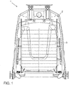
- Figure 1 shows a vehicle seat 1 in a view from the rear with a backrest frame 2 and a backrest cover 3.
- the backrest cover 3 is arranged in particular on the rear side of the vehicle seat 1.
- the vehicle seat 1 has a seat and backrest surface or an upholstery, but this is not shown.
- Such a vehicle seat 1 can be used in any vehicle, be it an automobile, an airplane or a boat.
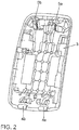
- FIG. 2 shows the side of the backrest cover 3 facing the vehicle seat 1 or the backrest frame 2.
- the backrest cover 3 is in particular shell-shaped and dimensionally stable.
- the backrest cover 3 comprises slide-in elements 4a and 4b which engage in the vehicle seat 1 or in the backrest frame 2 for fastening the backrest cover 3 to the vehicle seat 1.
- the insertion elements 4a and 4b are hook-shaped at their ends facing the vehicle seat 1.
- the number of insertion elements 4a to 4n is arbitrary, only one insertion element 4a can also be provided.
- the insert elements 4a and 4b enable a positive connection between the vehicle seat 1 or the backrest frame 2 and the backrest cover 3.
- the insertion elements 4a and 4b are preferably positioned in the lower region of the backrest cover 3.
- the backrest cover 3 furthermore comprises latching elements 5a and 5b, which engage / snap into the driver's seat 1 to fasten the backrest cover 3 to the vehicle seat 1 or engage / engage in the vehicle seat 1 or in the backrest frame 2 of the driver's seat 1, in particular in the inner circumference of the engage / snap in at least partially ring-shaped backrest frame 2.
- the locking elements 5a and 5b also enable a positive connection between the vehicle seat 1 or the backrest frame 2 and the backrest cover 3.
- the number of latching elements 5a to 5n is arbitrary.
- the backrest cover 3 can, for example, have only one latching element 5a.
- the backrest cover 3 can also have four latching elements 5a to 5d.
- Figure 3 shows a locking element 5a in more detail and in its interaction with the backrest cover 3 and the backrest frame 2 or the vehicle seat 1.
- the insertion elements 4a to 4n engage in the vehicle seat 1 or the backrest frame 2, preferably in the inner circumference of the backrest frame 2, and establish a first positive connection between the backrest cover 3 and the backrest frame 2 or the vehicle seat 1 (not shown).
- the latching element 5a is designed to be movable with respect to the backrest cover 3, that is to say floating, and is acted upon by a spring force.
- the locking element 5a is designed to be movable relative to the backrest cover 3 such that the locking element 5a executes a movement along a straight line, as in FIG Figure 3 is indicated by a double arrow.
- the locking element 5a is guided along a guide element 6 and cooperates with a spring 7, as in connection with the Figures 4 and 5 is described.
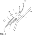
- Figure 4 shows a locking element 5a even more in detail, in particular in cooperation with the backrest cover 3 and the backrest frame 2 or the vehicle seat 1.
- the backrest cover 3 has a guide element 6 on the side facing the vehicle seat 1.
- the guide element 6 comprises in particular a plane or a surface or a path along which the latching element 5a is / is guided / guided, preferably is / can be guided in a straight line, relative to the backrest cover 3.
- the latching element 5a slides along the guide element 6 as a result of the spring load, that is to say it is in contact with the guide element 6 and is guided or moved by the guide element 6.
- the guide element 6 is integrally formed on the backrest cover 3 or is part of the backrest cover 3 or the backrest cover 3 itself.
- the guide element 6 is preferably also an abutment for a spring element 7 for applying a spring force to the latching element 5a.
- the spring element 7 is preferably a compression spring, for example with a cylindrical cross section.
- the locking element 5a has a contact surface 8.
- the contact surface 8 is arranged on the latching element 5a in an end region which points in the direction of the spring force acting on the latching element 5a.
- the contact surface 8 also faces the vehicle seat 1 or the backrest frame 2.
- the contact surface 8 is also inclined with respect to the longitudinal axis A of the locking element 5a.
- the locking element 5a also has a locking area 9, which is provided opposite the contact surface 8, also in an end area of the locking element 5a, which points in the direction of the force acting on the locking element 5a.
- the locking area 9 is preferably graduated. For this purpose, the locking element 5a in the direction of the contact surface 8 is excluded.
- the locking element 5a is shown in a sprung-in state.
- the insertion elements 4a to 4n engage in the vehicle seat 1 or the backrest frame 2 and establish a first positive connection between the backrest cover 3 and the backrest frame 2 or the vehicle seat 1.
- the latching element 5a is therefore deflected or subjected to a comparatively large spring force because the backrest cover 3 and thus the latching element 5a has been moved in the direction of the vehicle seat 1, so that the contact surface 8 and the vehicle seat 1 or the backrest frame 2 first come into contact in the contact area B.
- the locking element 5a is moved due to the inclination of the contact surface 8 along the guide element 6, since the back frame 2 is fixed that the length of the spring is influenced (shortened here).
- the latching element 5a springs out again and goes into an end position, with a certain application of the spring force remains so that tolerances between backrest cover 3 and vehicle seat 1 / backrest frame 2 are compensated for and the locking element 5a remains so securely and permanently.
Landscapes
- Engineering & Computer Science (AREA)
- Aviation & Aerospace Engineering (AREA)
- Transportation (AREA)
- Mechanical Engineering (AREA)
- Seats For Vehicles (AREA)
Description
- Die Erfindung betrifft eine Vorrichtung zur Befestigung einer Lehnenabdeckung an einem Fahrzeugsitz mit den Merkmalen gemäß den Patentansprüchen.
- Beispielsweise gemäß der
DE 10 2013 112 699 A1 ist es Stand der Technik, eine Lehnenabdeckung an einem Fahrzeugsitz dadurch zu befestigen, dass an der dem Fahrzeugsitz zugewandten Seite der Lehnenabdeckung Befestigungselemente in Form von Rasthaken angeordnet sind, welche in Befestigungslöcher eingreifen, die im Lehnenrahmen des Fahrzeugsitzes vorgesehen sind. Das bietet gute Möglichkeiten, Toleranzen des Lehnenrahmens in der Höhe auszugleichen. Diese Toleranzen können bis zu ± 3 mm in der Metallstruktur des Lehnenrahmens betragen. Von Nachteil ist es jedoch, dass die Rasthaken aus Festigkeitsgründen sehr groß sein müssen, bezogen auf den Lehnenrahmen. Große Rasthaken benötigen allerdings große Befestigungslöcher im Lehnenrahmen. Große Befestigungslöcher im Lehnenrahmen beeinträchtigen wiederum dessen Festigkeit. Dem könnte durch den Einsatz von zusätzlichem Material begegnet werden, was jedoch wiederum teuer und schwer ist. Darüber hinaus bietet die Metallstruktur des Lehnenrahmens häufig überhaupt keine Möglichkeit, große Befestigungslöcher einzubringen, da diese so konstruiert ist, dass sowohl Festigkeits- als auch Gewichtsanforderungen erfüllt werden. - Weiterhin ist es gemäß der
DE 10 2007 010 961 A1 bekannt, eine rückwärtige Lehnenabdeckung eines Fahrzeugsitzes mittels eines federnden Elementes mechanisch an dem Fahrzeugsitz zu befestigen. Das federnde Element ist als U-Feder ausgestaltet. An dem offenen Ende des federnden Elementes ist ein Haken angeordnet. Dieser Haken wird zur Befestigung der Lehnenabdeckung an dem Fahrzeugsitz über ein Rahmenteil des Fahrzeugsitzes geführt, so dass der Haken das Rahmenteil umgreift. Gute Möglichkeiten, Toleranzen des Lehnenrahmens in der Höhe auszugleichen, sind nicht gegeben. -
JP 2002 142914 A - Denkbar ist alternativ der Einsatz von Verschraubungen zur Befestigung einer Lehnenabdeckung an einem Fahrzeugsitz. Verschraubungen setzen jedoch auch die Einhaltung gewisser Toleranzen voraus und sind in der Massenfertigung von Nachteil, da deren Herstellung zeitaufwendig ist.
- Der Erfindung liegt nun die Aufgabe zugrunde, eine Möglichkeit bereitzustellen, eine Lehnenabdeckung sicher, passgenau und fehlertolerant an einem Fahrzeugsitz zu befestigen.
- Diese Aufgabe wird erfindungsgemäß dadurch gelöst, dass zur Befestigung einer Lehnenabdeckung an einem Fahrzeugsitz die Lehnenabdeckung zumindest ein Rastelement aufweist, das zur Herstellung einer Verbindung zwischen Lehnenabdeckung und Fahrzeugsitz an dem / in dem Fahrzeugsitz eingreift, wobei das Rastelement mit einer Federkraft beaufschlagt ist, die Lehnenabdeckung auf der dem Fahrzeugsitz zugewandten Seite ein Führungselement aufweist und das Rastelement gegenüber der Lehnenabdeckung entlang des Führungselementes beweglich ist.
- Das Führungselement ist gleichzeitig ein Widerlager für ein Federelement für eine Beaufschlagung des Rastelementes mit einer Federkraft. Das Federelement ist eine Druckfeder. Auf diese Weise werden verschiedene Funktionen in einem Bauteil kombiniert, was Platz und Aufwand spart.
- Mit anderen Worten ist das zumindest eine Rastelement beziehungsweise ist der zumindest eine Rasthaken, mit dem die Lehnenabdeckung in einem Montageschritt an dem Fahrzeugsitz befestigt wird, schwimmend an der Lehnenabdeckung gelagert. Dabei ist das Rastelement entlang einer durch das Führungselement definierten Führungsbahn beweglich. Dadurch, dass das federbelastete Rastelement schwimmend gelagert ist, müssen keine Befestigungslöcher/Durchbrüche im Fahrzeugsitz vorgesehen werden. Das federbelastete Rastelement greift einfach am beziehungsweise im Fahrzeugsitz ein, bevorzugt am Innenumfang des Lehnenrahmens des Fahrzeugsitzes. Folglich ist es nicht notwendig, enge Toleranzen einzuhalten, um einen mangelnden Festsitz der Lehnenabdeckung am Fahrzeugsitz zu verhindern. Vielmehr werden vorhandene Toleranzen, beispielsweise ein an der oberen Toleranzgrenze liegender Innenumfang des Fahrzeugsitzes beziehungsweise des Lehnenrahmens, durch die schwimmende Lagerung des Rastelements ausgeglichen. Dadurch, dass das Rastelement entlang einer definierten Führungsbahn geführt wird, ist ein Eingreifen und dauerhaftes Verbleiben des Rastelements in einem bestimmten Bereich des Fahrzeugsitzes beziehungsweise des Lehnenrahmens sichergestellt. Mit anderen Worten wird so die Lehnenabdeckung sicher befestigt. Durch die definierte Führungsbahn kann weiterhin den wechselnden Gegebenheiten bei unterschiedlichen Sitzen gezielt Rechnung getragen werden. Denkbar könnte es sein, die Führungsbahn zu neigen oder zu krümmen. Jedenfalls ist somit die erfindungsgemäße Vorrichtung zudem sehr flexibel. Der Einsatz großer und stabiler Rasthaken ist problemlos möglich.
- Weitere bevorzugte Ausgestaltungen der Erfindung ergeben sich aus den übrigen, in den Unteransprüchen genannten Merkmalen.
- Die verschiedenen in dieser Anmeldung genannten Ausführungsformen der Erfindung sind, sofern im Einzelfall nicht anders ausgeführt, mit Vorteil miteinander kombinierbar.
- Die Erfindung wird nachfolgend in Ausführungsbeispielen anhand der zugehörigen Zeichnungen erläutert. Es zeigen:
- Figur 1
- einen Fahrzeugsitz in einer Ansicht von hinten,
- Figur 2
- die dem Fahrzeugsitz zugewandte Seite einer Lehnenabdeckung,
- Figur 3
- das Rastelement im Detail,
- Figur 4
- das Rastelement noch mehr im Detail, und
- Figur 5
- das eingerastete Rastelement.
-
Figur 1 zeigt einen Fahrzeugsitz 1 in einer Ansicht von hinten mit einem Lehnenrahmen 2 und einer Lehnenabdeckung 3. Die Lehnenabdeckung 3 ist insbesondere an der rückwärtigen Seite des Fahrzeugsitzes 1 angeordnet. Der Fahrzeugsitz 1 weist, wie allgemein bekannt, eine Sitz- und Lehnenfläche beziehungsweise eine Polsterung auf, was jedoch nicht gezeigt ist. Ein solcher Fahrzeugsitz 1 kann in jedem möglichen Fahrzeug eingesetzt werden, sei es ein Automobil, ein Flugzeug oder ein Boot. -
Figur 2 zeigt die dem Fahrzeugsitz 1 beziehungsweise dem Lehnenrahmen 2 zugewandte Seite der Lehnenabdeckung 3. Die Lehnenabdeckung 3 ist insbesondere schalenförmig und formstabil. Die Lehnenabdeckung 3 umfasst Einschubelemente 4a und 4b, welche zur Befestigung der Lehnenabdeckung 3 am Fahrzeugsitz 1 in den Fahrzeugsitz 1 beziehungsweise in den Lehnenrahmen 2 eingreifen. Dazu sind die Einschubelemente 4a und 4b an ihren dem Fahrzeugsitz 1 zugewandten Enden hakenförmig ausgebildet. Die Anzahl der Einschubelemente 4a bis 4n ist beliebig, es kann auch nur ein Einschubelement 4a vorgesehen sein. Jedenfalls wird mittels der Einschubelemente 4a und 4b eine formschlüssige Verbindung zwischen dem Fahrzeugsitz 1 beziehungsweise dem Lehnenrahmen 2 und der Lehnenabdeckung 3 ermöglicht. Die Einschubelemente 4a und 4b sind bevorzugt im unteren Bereich der Lehnenabdeckung 3 positioniert. Die Lehnenabdeckung 3 umfasst weiterhin Rastelemente 5a und 5b, welche zur Befestigung der Lehnenabdeckung 3 an dem Fahrzeugsitz 1 eben an dem Fahrersitz 1 eingreifen/einrasten oder in den Fahrzeugsitz 1 eingreifen/einrasten oder in den Lehnenrahmen 2 des Fahrersitzes 1, insbesondere in den Innenumfang des zumindest teilweise ringförmig ausgebildeten Lehnenrahmens 2, eingreifen/einrasten. Mittels der Rastelemente 5a und 5b wird ebenfalls eine formschlüssige Verbindung zwischen dem Fahrzeugsitz 1 beziehungsweise dem Lehnenrahmen 2 und der Lehnenabdeckung 3 ermöglicht. Die Anzahl der Rastelemente 5a bis 5n ist beliebig. Die Lehnenabdeckung 3 kann beispielsweise lediglich ein Rastelement 5a aufweisen. Die Lehnenabdeckung 3 kann auch vier Rastelemente 5a bis 5d aufweisen. -
Figur 3 zeigt ein Rastelement 5a mehr im Detail und in seinem Zusammenwirken mit der Lehnenabdeckung 3 und dem Lehnenrahmen 2 beziehungsweise dem Fahrzeugsitz 1. GemäßFigur 3 greifen die Einschubelemente 4a bis 4n in den Fahrzeugsitz 1 beziehungsweise den Lehnenrahmen 2, bevorzugt in den Innenumfang des Lehnenrahmens 2, ein und stellen eine erste formschlüssige Verbindung zwischen Lehnenabdeckung 3 und Lehnenrahmen 2 beziehungsweise Fahrzeugsitz 1 her (nicht gezeigt). Das Rastelement 5a ist gegenüber der Lehnenabdeckung 3 beweglich ausgeführt, das heißt schwimmend gelagert, und mit einer Federkraft beaufschlagt. Insbesondere ist das Rastelement 5a derart gegenüber der Lehnenabdeckung 3 beweglich ausgeführt, dass das Rastelement 5a eine Bewegung entlang einer geraden Linie ausführt, wie inFigur 3 durch einen Doppelpfeil angedeutet ist. Das Rastelement 5a wird entlang eines Führungselementes 6 geführt und wirkt mit einer Feder 7 zusammen, wie im Zusammenhang mit denFiguren 4 und5 beschrieben wird. -
Figur 4 zeigt ein Rastelement 5a noch mehr im Detail, insbesondere im Zusammenwirken mit der Lehnenabdeckung 3 und dem Lehnenrahmen 2 beziehungsweise dem Fahrzeugsitz 1. Erfindungsgemäß weist die Lehnenabdeckung 3 auf der dem Fahrzeugsitz 1 zugewandten Seite ein Führungselement 6 auf. Das Führungselement 6 umfasst insbesondere eine Ebene beziehungsweise eine Fläche oder eine Bahn, entlang der das Rastelement 5a gegenüber der Lehnenabdeckung 3 beweglich ist / geführt wird, bevorzugt geradlinig beweglich ist / geführt wird. Insbesondere gleitet das Rastelement 5a entlang des Führungselementes 6 infolge der Federbelastung, steht also mit dem Führungselement 6 in Kontakt und wird durch das Führungselement 6 geleitet beziehungsweise geführt bewegt. Das Führungselement 6 ist an die Lehnenabdeckung 3 angeformt beziehungsweise Teil der Lehnenabdeckung 3 oder die Lehnenabdeckung 3 selbst. Das Führungselement 6 ist bevorzugt gleichzeitig Widerlager für ein Federelement 7 für eine Beaufschlagung des Rastelementes 5a mit einer Federkraft. Das Federelement 7 ist bevorzugt eine Druckfeder, beispielsweise mit einem zylindrischen Querschnitt. Das Rastelement 5a weist eine Kontaktfläche 8 auf. Die Kontaktfläche 8 ist an dem Rastelement 5a in einem Endbereich angeordnet, welcher in Richtung der auf das Rastelement 5a wirkenden Federkraft weist. Die Kontaktfläche 8 ist ferner dem Fahrzeugsitz 1 beziehungsweise dem Lehnenrahmen 2 zugewandt. Die Kontaktfläche 8 ist darüber hinaus gegenüber der Längsachse A des Rastelementes 5a geneigt. Das Rastelement 5a weist weiterhin einen Rastbereich 9 auf, welcher gegenüber der Kontaktfläche 8 vorgesehen ist, ebenfalls in einem Endbereich des Rastelementes 5a, welcher in Richtung der auf das Rastelement 5a wirkenden Kraft weist. Der Rastbereich 9 ist bevorzugt abgestuft. Dazu ist das Rastelement 5a in Richtung der Kontaktfläche 8 ausgenommen. - In
Figur 4 ist das Rastelement 5a in einem eingefederten Zustand gezeigt. Außerdem greifen die Einschubelemente 4a bis 4n in den Fahrzeugsitz 1 beziehungsweise den Lehnenrahmen 2 ein und stellen eine erste formschlüssige Verbindung zwischen Lehnenabdeckung 3 und Lehnenrahmen 2 beziehungsweise Fahrzeugsitz 1 her. Das Rastelement 5a ist deshalb eingefedert beziehungsweise mit einer vergleichsweise großen Federkraft beaufschlagt, weil die Lehnenabdeckung 3 und somit das Rastelement 5a in Richtung des Fahrzeugsitzes 1 bewegt wurde, so dass die Kontaktfläche 8 und der Fahrzeugsitz 1 beziehungsweise der Lehnenrahmen 2 zunächst im Kontaktbereich B in Kontakt gebracht wurden und im weiteren Verlauf das Rastelement 5a infolge der Neigung der Kontaktfläche 8 derart entlang des Führungselementes 6 bewegt wird, da der Lehnenrahmen 2 feststeht, dass die Länge der Feder beeinflusst (hier verkürzt) wird. Zur endgültigen Befestigung der Lehnenabdeckung 3 an dem Lehnenrahmen 2 beziehungsweise dem Fahrzeugsitz 1 federt das Rastelement 5a wieder aus und geht in eine Endposition, wobei eine gewisse Beaufschlagung mit der Federkraft bestehen bleibt, so dass Toleranzen zwischen Lehnenabdeckung 3 und Fahrzeugsitz 1/Lehnenrahmen 2 ausgeglichen werden und das Rastelement 5a sicher und dauerhaft so verharrt. Dieses Ausfedern erfolgt dadurch, dass der Lehnenrahmen 2 im Kontaktbereich B den Kontakt zur Kontaktfläche 8 verliert, die Lehnenabdeckung 3 einschließlich dem Rastelement 5a weiter in Richtung des Fahrzeugsitzes 1 bewegt wird und die Federkraft das nunmehr nicht mehr in seiner Längenausdehnung durch den Kontakt mit dem Lehnenrahmen 2 behinderte Rastelement 5a freigibt. Jedenfalls kommt der Bereich B des Lehnenrahmens 2 im abgestuften Rastbereich 9 zum Stillstand, das heißt rastet ein. Das ist inFigur 5 gezeigt. Somit ist eine weitere formschlüssige Verbindung zwischen Lehnenabdeckung 3 und Lehnenrahmen 2 beziehungsweise Fahrzeugsitz 1 hergestellt. -
- 1
- Fahrzeugsitz
- 2
- Lehnenrahmen
- 3
- Lehnenabdeckung
- 4a, 4b, 4n
- Einschubelement
- 5a, 5b, 5n
- Rastelement
- 6
- Führungselement
- 7
- Federelement
- 8
- Kontaktfläche
- 9
- Rastbereich
- A
- Längsachse
- B
- Kontaktbereich
Claims (4)
- Vorrichtung mit einer Lehnenabdeckung zur Befestigung der Lehnenabdeckung (3) an einem Fahrzeugsitz (1), wobei die Lehnenabdeckung (3) zumindest ein Rastelement (5a, 5b, 5n) aufweist, welches zur Herstellung einer Verbindung zwischen Lehnenabdeckung (3) und Fahrzeugsitz (1) in den Fahrzeugsitz (1) eingreifen kann, wobei das Rastelement (5a, 5b, 5n) mit einer Federkraft beaufschlagt ist, die Lehnenabdeckung (3) auf der dem Fahrzeugsitz (1) zugewandten Seite ein Führungselement (6) aufweist und das Rastelement (5a, 5b, 5n) gegenüber der Lehnenabdeckung (3) entlang des Führungselementes (6) geführt ist, das Führungselement (6) eine Fläche aufweist, entlang der das Rastelement (5a, 5b, 5n) gegenüber der Lehnenabdeckung (3) geführt ist, das Rastelement (5a, 5b, 5n) gegenüber der Lehnenabdeckung (3) entlang des Führungselementes (6) geradlinig geführt ist, das Führungselement (6) an die Lehnenabdeckung (3) angeformt ist, dadurch gekennzeichnet, dass
das Führungselement (6) zusätzlich ein Widerlager für ein Federelement (7) für eine Beaufschlagung des Rastelementes (5a, 5b, 5n) mit einer Federkraft aufweist, und das Federelement (7) eine Druckfeder ist. - Vorrichtung nach Anspruch 1, dadurch gekennzeichnet, dass die Lehnenabdeckung (3) Einschubelemente (4a, 4b, 4n) aufweist, welche zur Befestigung der Lehnenabdeckung (3) am Fahrzeugsitz (1) in den Fahrzeugsitz (1) eingreifen können, so dass mittels der Einschubelemente (4a, 4b, 4n) eine erste formschlüssige Verbindung zwischen dem Fahrzeugsitz (1) und der Lehnenabdeckung (3) hergestellt wird und mittels des zumindest einen Rastelementes (5a, 5b, 5n), das ebenfalls in den Fahrzeugsitz (1) eingreifen kann, eine zweite formschlüssige Verbindung zwischen dem Fahrzeugsitz (1) und der Lehnenabdeckung (3) hergestellt werden kann.
- Vorrichtung nach Anspruch 2, dadurch gekennzeichnet, dass das zumindest eine Rastelement (5a, 5b, 5n) in den Lehnenrahmen (2) des Fahrzeugsitzes (1) eingreifen kann und/oder die Einschubelemente (4a, 4b, 4n) in den Lehnenrahmen (2) des Fahrzeugsitzes (1) eingreifen können.
- Vorrichtung nach den Ansprüchen 1 bis 3, dadurch gekennzeichnet, dass das zumindest eine Rastelement (5a, 5b, 5n) eine Kontaktfläche (8) aufweist, die an dem Rastelement (5a, 5b, 5n) in einem Endbereich angeordnet ist, welcher in Richtung der auf das Rastelement (5a, 5b, 5n) wirkenden Federkraft weist, wobei die Kontaktfläche (8) dem Fahrzeugsitz (1) zugewandt ist und gegenüber der Längsachse (A) des Rastelementes (5a, 5b, 5n) geneigt ist sowie das Rastelement (5a, 5b, 5n) weiterhin einen Rastbereich (9) aufweist, welcher gegenüber der Kontaktfläche (8) vorgesehen ist, ebenfalls in einem Endbereich des Rastelementes (5a), welcher in Richtung der auf das Rastelement (5a, 5b, 5n) wirkenden Federkraft weist, wobei der Rastbereich (9) abgestuft ist.
Applications Claiming Priority (2)
| Application Number | Priority Date | Filing Date | Title |
|---|---|---|---|
| DE102016210242.7A DE102016210242A1 (de) | 2016-06-09 | 2016-06-09 | Vorrichtung und Verfahren zur Befestigung einer Lehnenabdeckung an einem Fahrzeugsitz |
| PCT/EP2017/064055 WO2017212005A1 (de) | 2016-06-09 | 2017-06-09 | Vorrichtung und verfahren zur befestigung einer lehnenabdeckung an einem fahrzeugsitz |
Publications (2)
| Publication Number | Publication Date |
|---|---|
| EP3468834A1 EP3468834A1 (de) | 2019-04-17 |
| EP3468834B1 true EP3468834B1 (de) | 2020-08-05 |
Family
ID=59030948
Family Applications (1)
| Application Number | Title | Priority Date | Filing Date |
|---|---|---|---|
| EP17728839.6A Active EP3468834B1 (de) | 2016-06-09 | 2017-06-09 | Vorrichtung und verfahren zur befestigung einer lehnenabdeckung an einem fahrzeugsitz |
Country Status (5)
| Country | Link |
|---|---|
| US (1) | US10640022B2 (de) |
| EP (1) | EP3468834B1 (de) |
| CN (1) | CN109153346B (de) |
| DE (1) | DE102016210242A1 (de) |
| WO (1) | WO2017212005A1 (de) |
Families Citing this family (1)
| Publication number | Priority date | Publication date | Assignee | Title |
|---|---|---|---|---|
| US12558363B2 (en) * | 2019-12-30 | 2026-02-24 | Devicare SL | Compositions for clinical complications associated to devices implanted in the urinary tract |
Family Cites Families (19)
| Publication number | Priority date | Publication date | Assignee | Title |
|---|---|---|---|---|
| DE2930719C2 (de) * | 1979-07-28 | 1982-12-16 | Daimler-Benz Ag, 7000 Stuttgart | Vorrichtung zur Befestigung einer Drucktaste an Druckbolzen |
| DE19650823C1 (de) * | 1996-12-07 | 1998-01-08 | Faure Bertrand Sitztech Gmbh | Sicherungsvorrichtung für einen elektrisch angetriebenen Kraftfahrzeugvordersitz |
| DE19846090C2 (de) | 1998-10-07 | 2003-05-22 | Faurecia Autositze Gmbh & Co | Kraftfahrzeugsitz mit Belüftungseinrichtung |
| JP2002142914A (ja) * | 2000-11-10 | 2002-05-21 | Johnson Controls Automotive Systems Corp | 車両用シートバックのバックボード取付構造 |
| FR2821029B1 (fr) | 2001-02-16 | 2003-08-08 | Faurecia Sieges Automobile | Element de siege pour vehicule |
| DE10250504C1 (de) | 2002-10-29 | 2003-10-23 | Faurecia Autositze Gmbh & Co | Rückenlehne für einen Fahrzeugsitz, insbesondere Kraftfahrzeugsitz |
| FR2851524B1 (fr) | 2003-02-21 | 2005-05-06 | Faurecia Sieges Automobile | Dossier de siege de vehicule automobile. |
| DE102005019907B4 (de) | 2005-04-29 | 2016-12-01 | Faurecia Autositze Gmbh | Rückenlehne eines Fahrzeugsitzes |
| DE102005058590B3 (de) * | 2005-12-07 | 2007-05-24 | Faurecia Autositze Gmbh | Befestigungsvorrichtung für Blenden und Abdeckungen in Kraftfahrzeugen |
| DE102005060481A1 (de) * | 2005-12-15 | 2007-06-21 | Faurecia Autositze Gmbh | Sitz, insbesondere Kraftfahrzeugsitz |
| US7549699B2 (en) * | 2006-08-21 | 2009-06-23 | Lear Corporation | Moveable back panel for a vehicle seat |
| DE102007010961B4 (de) | 2007-03-05 | 2020-11-12 | Faurecia Autositze Gmbh | Anti-Whiplash-Fahrzeugsitz |
| DE102010022394A1 (de) * | 2009-06-01 | 2010-12-23 | Kinetix Ag | Befestigungseinrichtung |
| JP5644688B2 (ja) * | 2011-06-14 | 2014-12-24 | トヨタ紡織株式会社 | 車両用シート |
| US9421888B2 (en) * | 2012-08-07 | 2016-08-23 | Ts Tech Co., Ltd. | Seat device for vehicle |
| JP5949299B2 (ja) | 2012-08-08 | 2016-07-06 | トヨタ紡織株式会社 | クリップ |
| KR101481291B1 (ko) | 2013-07-11 | 2015-01-09 | 현대자동차주식회사 | 차량용 시트 |
| JP3186511U (ja) * | 2013-07-30 | 2013-10-10 | Ykk株式会社 | 表皮材止着用クリップ |
| US9649963B2 (en) * | 2014-03-04 | 2017-05-16 | Ford Global Technologies, Pllc | Trim and foam assembly for a vehicle seat |
-
2016
- 2016-06-09 DE DE102016210242.7A patent/DE102016210242A1/de not_active Withdrawn
-
2017
- 2017-06-09 CN CN201780032435.6A patent/CN109153346B/zh active Active
- 2017-06-09 EP EP17728839.6A patent/EP3468834B1/de active Active
- 2017-06-09 WO PCT/EP2017/064055 patent/WO2017212005A1/de not_active Ceased
-
2018
- 2018-12-10 US US16/215,232 patent/US10640022B2/en not_active Expired - Fee Related
Non-Patent Citations (1)
| Title |
|---|
| None * |
Also Published As
| Publication number | Publication date |
|---|---|
| CN109153346A (zh) | 2019-01-04 |
| EP3468834A1 (de) | 2019-04-17 |
| US10640022B2 (en) | 2020-05-05 |
| CN109153346B (zh) | 2021-11-23 |
| DE102016210242A1 (de) | 2017-12-14 |
| US20190106032A1 (en) | 2019-04-11 |
| WO2017212005A1 (de) | 2017-12-14 |
Similar Documents
| Publication | Publication Date | Title |
|---|---|---|
| DE102009024983A1 (de) | Verbindungsbaugruppe | |
| EP3907129B1 (de) | Verbinder und verfahren zum verbinden eines spants und eines stringers einer rumpfstruktur eines luftfahrzeugs, rumpfstruktur und luftfahrzeug | |
| DE112012007052B4 (de) | Sitzschienenanordnung mit auswählbaren Endstopppositionen | |
| DE102009052512A1 (de) | Neigungsversteller für Fahrzeuge | |
| EP3233563B1 (de) | Abdeckung für ein schienenpaar eines längsverstellbaren fahrzeugsitzes sowie schienenpaar | |
| DE102017107105A1 (de) | Montagesystem zum werkzeuglosen montieren einer mittelkonsole in einem kraftfahrzeug | |
| DE102018201828B4 (de) | Toleranzausgleichsvorrichtung und Verfahren zur Montage einer Toleranzausgleichsvorrichtung | |
| EP3934932B1 (de) | Längseinstellvorrichtung zur motorischen längseinstellung eines fahrzeugsitzes sowie fahrzeugsitz | |
| EP1609703B1 (de) | Querträger | |
| DE102017216430A1 (de) | Bauteilsystem zur Fixierung eines Verkleidungsteils und Kraftfahrzeug | |
| WO2017212005A1 (de) | Vorrichtung und verfahren zur befestigung einer lehnenabdeckung an einem fahrzeugsitz | |
| DE102019135343A1 (de) | Fahrzeugverkleidung | |
| DE102018209343B3 (de) | Kraftfahrzeug | |
| DE102005035319A1 (de) | Schiene zur Halterung und/oder Sicherung von Gegenständen | |
| DE202005020078U1 (de) | Gassackmodul | |
| DE602004004292T2 (de) | Abgasleitungshalter, verfahren zur befestigung eines abgasleitungshalters | |
| DE102015100997B4 (de) | Verbindungsanordnung eines ersten Karosseriebauteils an einem zweiten Karosseriebauteil für ein Kraftfahrzeug, insbesondere Personenkraftfahrzeug | |
| EP4003790B1 (de) | Verkleidungsanordnung zur innenraumausstattung eines kraftfahrzeugs, eine kraftfahrzeugtür sowie kraftfahrzeug | |
| DE102023132033A1 (de) | Karosseriesichtelement einer Kraftfahrzeugkarosserie mit einem Abdeckelement | |
| EP3501900B1 (de) | Innenmodul für einen laderaum eines fahrzeuges, laderaumverkleidung sowie herstellverfahren zum herstellen eines innenmoduls | |
| DE102006059096A1 (de) | Baugruppe zur fahrzeugseitigen Befestigung eines Gurtschlosses | |
| EP3309416A1 (de) | Befestigungsmittel zur rastenden befestigung in einer auslassung sowie befestigungssystem enthaltend dieses befestigungsmittel | |
| DE102006057292B4 (de) | Lenkgetriebe für eine Zahnstangenlenkung | |
| DE102015215990A1 (de) | Gelenkzapfen und Betätigungshebel | |
| DE102016118774A1 (de) | Vorrichtung zum Ausgleichen von Toleranzen |
Legal Events
| Date | Code | Title | Description |
|---|---|---|---|
| STAA | Information on the status of an ep patent application or granted ep patent |
Free format text: STATUS: UNKNOWN |
|
| STAA | Information on the status of an ep patent application or granted ep patent |
Free format text: STATUS: THE INTERNATIONAL PUBLICATION HAS BEEN MADE |
|
| PUAI | Public reference made under article 153(3) epc to a published international application that has entered the european phase |
Free format text: ORIGINAL CODE: 0009012 |
|
| STAA | Information on the status of an ep patent application or granted ep patent |
Free format text: STATUS: REQUEST FOR EXAMINATION WAS MADE |
|
| 17P | Request for examination filed |
Effective date: 20190109 |
|
| AK | Designated contracting states |
Kind code of ref document: A1 Designated state(s): AL AT BE BG CH CY CZ DE DK EE ES FI FR GB GR HR HU IE IS IT LI LT LU LV MC MK MT NL NO PL PT RO RS SE SI SK SM TR |
|
| AX | Request for extension of the european patent |
Extension state: BA ME |
|
| DAV | Request for validation of the european patent (deleted) | ||
| DAX | Request for extension of the european patent (deleted) | ||
| GRAP | Despatch of communication of intention to grant a patent |
Free format text: ORIGINAL CODE: EPIDOSNIGR1 |
|
| STAA | Information on the status of an ep patent application or granted ep patent |
Free format text: STATUS: GRANT OF PATENT IS INTENDED |
|
| INTG | Intention to grant announced |
Effective date: 20200422 |
|
| GRAS | Grant fee paid |
Free format text: ORIGINAL CODE: EPIDOSNIGR3 |
|
| GRAA | (expected) grant |
Free format text: ORIGINAL CODE: 0009210 |
|
| STAA | Information on the status of an ep patent application or granted ep patent |
Free format text: STATUS: THE PATENT HAS BEEN GRANTED |
|
| AK | Designated contracting states |
Kind code of ref document: B1 Designated state(s): AL AT BE BG CH CY CZ DE DK EE ES FI FR GB GR HR HU IE IS IT LI LT LU LV MC MK MT NL NO PL PT RO RS SE SI SK SM TR |
|
| REG | Reference to a national code |
Ref country code: GB Ref legal event code: FG4D Free format text: NOT ENGLISH |
|
| REG | Reference to a national code |
Ref country code: CH Ref legal event code: EP |
|
| REG | Reference to a national code |
Ref country code: AT Ref legal event code: REF Ref document number: 1298271 Country of ref document: AT Kind code of ref document: T Effective date: 20200815 |
|
| REG | Reference to a national code |
Ref country code: DE Ref legal event code: R096 Ref document number: 502017006581 Country of ref document: DE |
|
| REG | Reference to a national code |
Ref country code: IE Ref legal event code: FG4D Free format text: LANGUAGE OF EP DOCUMENT: GERMAN |
|
| REG | Reference to a national code |
Ref country code: LT Ref legal event code: MG4D |
|
| REG | Reference to a national code |
Ref country code: NL Ref legal event code: MP Effective date: 20200805 |
|
| PG25 | Lapsed in a contracting state [announced via postgrant information from national office to epo] |
Ref country code: BG Free format text: LAPSE BECAUSE OF FAILURE TO SUBMIT A TRANSLATION OF THE DESCRIPTION OR TO PAY THE FEE WITHIN THE PRESCRIBED TIME-LIMIT Effective date: 20201105 Ref country code: SE Free format text: LAPSE BECAUSE OF FAILURE TO SUBMIT A TRANSLATION OF THE DESCRIPTION OR TO PAY THE FEE WITHIN THE PRESCRIBED TIME-LIMIT Effective date: 20200805 Ref country code: NO Free format text: LAPSE BECAUSE OF FAILURE TO SUBMIT A TRANSLATION OF THE DESCRIPTION OR TO PAY THE FEE WITHIN THE PRESCRIBED TIME-LIMIT Effective date: 20201105 Ref country code: ES Free format text: LAPSE BECAUSE OF FAILURE TO SUBMIT A TRANSLATION OF THE DESCRIPTION OR TO PAY THE FEE WITHIN THE PRESCRIBED TIME-LIMIT Effective date: 20200805 Ref country code: GR Free format text: LAPSE BECAUSE OF FAILURE TO SUBMIT A TRANSLATION OF THE DESCRIPTION OR TO PAY THE FEE WITHIN THE PRESCRIBED TIME-LIMIT Effective date: 20201106 Ref country code: LT Free format text: LAPSE BECAUSE OF FAILURE TO SUBMIT A TRANSLATION OF THE DESCRIPTION OR TO PAY THE FEE WITHIN THE PRESCRIBED TIME-LIMIT Effective date: 20200805 Ref country code: FI Free format text: LAPSE BECAUSE OF FAILURE TO SUBMIT A TRANSLATION OF THE DESCRIPTION OR TO PAY THE FEE WITHIN THE PRESCRIBED TIME-LIMIT Effective date: 20200805 Ref country code: PT Free format text: LAPSE BECAUSE OF FAILURE TO SUBMIT A TRANSLATION OF THE DESCRIPTION OR TO PAY THE FEE WITHIN THE PRESCRIBED TIME-LIMIT Effective date: 20201207 Ref country code: HR Free format text: LAPSE BECAUSE OF FAILURE TO SUBMIT A TRANSLATION OF THE DESCRIPTION OR TO PAY THE FEE WITHIN THE PRESCRIBED TIME-LIMIT Effective date: 20200805 |
|
| PG25 | Lapsed in a contracting state [announced via postgrant information from national office to epo] |
Ref country code: RS Free format text: LAPSE BECAUSE OF FAILURE TO SUBMIT A TRANSLATION OF THE DESCRIPTION OR TO PAY THE FEE WITHIN THE PRESCRIBED TIME-LIMIT Effective date: 20200805 Ref country code: LV Free format text: LAPSE BECAUSE OF FAILURE TO SUBMIT A TRANSLATION OF THE DESCRIPTION OR TO PAY THE FEE WITHIN THE PRESCRIBED TIME-LIMIT Effective date: 20200805 Ref country code: PL Free format text: LAPSE BECAUSE OF FAILURE TO SUBMIT A TRANSLATION OF THE DESCRIPTION OR TO PAY THE FEE WITHIN THE PRESCRIBED TIME-LIMIT Effective date: 20200805 Ref country code: NL Free format text: LAPSE BECAUSE OF FAILURE TO SUBMIT A TRANSLATION OF THE DESCRIPTION OR TO PAY THE FEE WITHIN THE PRESCRIBED TIME-LIMIT Effective date: 20200805 Ref country code: IS Free format text: LAPSE BECAUSE OF FAILURE TO SUBMIT A TRANSLATION OF THE DESCRIPTION OR TO PAY THE FEE WITHIN THE PRESCRIBED TIME-LIMIT Effective date: 20201205 |
|
| PG25 | Lapsed in a contracting state [announced via postgrant information from national office to epo] |
Ref country code: RO Free format text: LAPSE BECAUSE OF FAILURE TO SUBMIT A TRANSLATION OF THE DESCRIPTION OR TO PAY THE FEE WITHIN THE PRESCRIBED TIME-LIMIT Effective date: 20200805 Ref country code: CZ Free format text: LAPSE BECAUSE OF FAILURE TO SUBMIT A TRANSLATION OF THE DESCRIPTION OR TO PAY THE FEE WITHIN THE PRESCRIBED TIME-LIMIT Effective date: 20200805 Ref country code: DK Free format text: LAPSE BECAUSE OF FAILURE TO SUBMIT A TRANSLATION OF THE DESCRIPTION OR TO PAY THE FEE WITHIN THE PRESCRIBED TIME-LIMIT Effective date: 20200805 Ref country code: EE Free format text: LAPSE BECAUSE OF FAILURE TO SUBMIT A TRANSLATION OF THE DESCRIPTION OR TO PAY THE FEE WITHIN THE PRESCRIBED TIME-LIMIT Effective date: 20200805 Ref country code: SM Free format text: LAPSE BECAUSE OF FAILURE TO SUBMIT A TRANSLATION OF THE DESCRIPTION OR TO PAY THE FEE WITHIN THE PRESCRIBED TIME-LIMIT Effective date: 20200805 |
|
| REG | Reference to a national code |
Ref country code: DE Ref legal event code: R097 Ref document number: 502017006581 Country of ref document: DE |
|
| PG25 | Lapsed in a contracting state [announced via postgrant information from national office to epo] |
Ref country code: AL Free format text: LAPSE BECAUSE OF FAILURE TO SUBMIT A TRANSLATION OF THE DESCRIPTION OR TO PAY THE FEE WITHIN THE PRESCRIBED TIME-LIMIT Effective date: 20200805 |
|
| PLBE | No opposition filed within time limit |
Free format text: ORIGINAL CODE: 0009261 |
|
| STAA | Information on the status of an ep patent application or granted ep patent |
Free format text: STATUS: NO OPPOSITION FILED WITHIN TIME LIMIT |
|
| PG25 | Lapsed in a contracting state [announced via postgrant information from national office to epo] |
Ref country code: SK Free format text: LAPSE BECAUSE OF FAILURE TO SUBMIT A TRANSLATION OF THE DESCRIPTION OR TO PAY THE FEE WITHIN THE PRESCRIBED TIME-LIMIT Effective date: 20200805 |
|
| 26N | No opposition filed |
Effective date: 20210507 |
|
| PG25 | Lapsed in a contracting state [announced via postgrant information from national office to epo] |
Ref country code: IT Free format text: LAPSE BECAUSE OF FAILURE TO SUBMIT A TRANSLATION OF THE DESCRIPTION OR TO PAY THE FEE WITHIN THE PRESCRIBED TIME-LIMIT Effective date: 20200805 |
|
| PG25 | Lapsed in a contracting state [announced via postgrant information from national office to epo] |
Ref country code: SI Free format text: LAPSE BECAUSE OF FAILURE TO SUBMIT A TRANSLATION OF THE DESCRIPTION OR TO PAY THE FEE WITHIN THE PRESCRIBED TIME-LIMIT Effective date: 20200805 |
|
| PG25 | Lapsed in a contracting state [announced via postgrant information from national office to epo] |
Ref country code: MC Free format text: LAPSE BECAUSE OF FAILURE TO SUBMIT A TRANSLATION OF THE DESCRIPTION OR TO PAY THE FEE WITHIN THE PRESCRIBED TIME-LIMIT Effective date: 20200805 |
|
| REG | Reference to a national code |
Ref country code: CH Ref legal event code: PL |
|
| REG | Reference to a national code |
Ref country code: BE Ref legal event code: MM Effective date: 20210630 |
|
| PG25 | Lapsed in a contracting state [announced via postgrant information from national office to epo] |
Ref country code: LU Free format text: LAPSE BECAUSE OF NON-PAYMENT OF DUE FEES Effective date: 20210609 |
|
| PG25 | Lapsed in a contracting state [announced via postgrant information from national office to epo] |
Ref country code: LI Free format text: LAPSE BECAUSE OF NON-PAYMENT OF DUE FEES Effective date: 20210630 Ref country code: IE Free format text: LAPSE BECAUSE OF NON-PAYMENT OF DUE FEES Effective date: 20210609 Ref country code: CH Free format text: LAPSE BECAUSE OF NON-PAYMENT OF DUE FEES Effective date: 20210630 |
|
| PG25 | Lapsed in a contracting state [announced via postgrant information from national office to epo] |
Ref country code: BE Free format text: LAPSE BECAUSE OF NON-PAYMENT OF DUE FEES Effective date: 20210630 |
|
| PGFP | Annual fee paid to national office [announced via postgrant information from national office to epo] |
Ref country code: GB Payment date: 20220621 Year of fee payment: 6 |
|
| PGFP | Annual fee paid to national office [announced via postgrant information from national office to epo] |
Ref country code: FR Payment date: 20220623 Year of fee payment: 6 |
|
| P01 | Opt-out of the competence of the unified patent court (upc) registered |
Effective date: 20230523 |
|
| PG25 | Lapsed in a contracting state [announced via postgrant information from national office to epo] |
Ref country code: CY Free format text: LAPSE BECAUSE OF FAILURE TO SUBMIT A TRANSLATION OF THE DESCRIPTION OR TO PAY THE FEE WITHIN THE PRESCRIBED TIME-LIMIT Effective date: 20200805 |
|
| PG25 | Lapsed in a contracting state [announced via postgrant information from national office to epo] |
Ref country code: HU Free format text: LAPSE BECAUSE OF FAILURE TO SUBMIT A TRANSLATION OF THE DESCRIPTION OR TO PAY THE FEE WITHIN THE PRESCRIBED TIME-LIMIT; INVALID AB INITIO Effective date: 20170609 |
|
| REG | Reference to a national code |
Ref country code: AT Ref legal event code: MM01 Ref document number: 1298271 Country of ref document: AT Kind code of ref document: T Effective date: 20220609 |
|
| PG25 | Lapsed in a contracting state [announced via postgrant information from national office to epo] |
Ref country code: AT Free format text: LAPSE BECAUSE OF NON-PAYMENT OF DUE FEES Effective date: 20220609 |
|
| GBPC | Gb: european patent ceased through non-payment of renewal fee |
Effective date: 20230609 |
|
| PG25 | Lapsed in a contracting state [announced via postgrant information from national office to epo] |
Ref country code: MK Free format text: LAPSE BECAUSE OF FAILURE TO SUBMIT A TRANSLATION OF THE DESCRIPTION OR TO PAY THE FEE WITHIN THE PRESCRIBED TIME-LIMIT Effective date: 20200805 Ref country code: GB Free format text: LAPSE BECAUSE OF NON-PAYMENT OF DUE FEES Effective date: 20230609 |
|
| PG25 | Lapsed in a contracting state [announced via postgrant information from national office to epo] |
Ref country code: FR Free format text: LAPSE BECAUSE OF NON-PAYMENT OF DUE FEES Effective date: 20230630 |
|
| PG25 | Lapsed in a contracting state [announced via postgrant information from national office to epo] |
Ref country code: TR Free format text: LAPSE BECAUSE OF FAILURE TO SUBMIT A TRANSLATION OF THE DESCRIPTION OR TO PAY THE FEE WITHIN THE PRESCRIBED TIME-LIMIT Effective date: 20200805 |
|
| PG25 | Lapsed in a contracting state [announced via postgrant information from national office to epo] |
Ref country code: MT Free format text: LAPSE BECAUSE OF FAILURE TO SUBMIT A TRANSLATION OF THE DESCRIPTION OR TO PAY THE FEE WITHIN THE PRESCRIBED TIME-LIMIT Effective date: 20200805 |
|
| PGFP | Annual fee paid to national office [announced via postgrant information from national office to epo] |
Ref country code: DE Payment date: 20250630 Year of fee payment: 9 |