EP3467482B1 - Methods and system for performance assessment of cleaning operations - Google Patents
Methods and system for performance assessment of cleaning operations Download PDFInfo
- Publication number
- EP3467482B1 EP3467482B1 EP18197940.2A EP18197940A EP3467482B1 EP 3467482 B1 EP3467482 B1 EP 3467482B1 EP 18197940 A EP18197940 A EP 18197940A EP 3467482 B1 EP3467482 B1 EP 3467482B1
- Authority
- EP
- European Patent Office
- Prior art keywords
- test strip
- image
- pixel
- color
- transformation
- Prior art date
- Legal status (The legal status is an assumption and is not a legal conclusion. Google has not performed a legal analysis and makes no representation as to the accuracy of the status listed.)
- Active
Links
Images














Classifications
-
- A—HUMAN NECESSITIES
- A61—MEDICAL OR VETERINARY SCIENCE; HYGIENE
- A61L—METHODS OR APPARATUS FOR STERILISING MATERIALS OR OBJECTS IN GENERAL; DISINFECTION, STERILISATION OR DEODORISATION OF AIR; CHEMICAL ASPECTS OF BANDAGES, DRESSINGS, ABSORBENT PADS OR SURGICAL ARTICLES; MATERIALS FOR BANDAGES, DRESSINGS, ABSORBENT PADS OR SURGICAL ARTICLES
- A61L2/00—Disinfection or sterilisation of materials or objects, in general; Accessories therefor
- A61L2/26—Accessories
- A61L2/28—Devices for testing the effectiveness or completeness of sterilisation or disinfection, e.g. indicators which change colour
-
- G—PHYSICS
- G06—COMPUTING OR CALCULATING; COUNTING
- G06T—IMAGE DATA PROCESSING OR GENERATION, IN GENERAL
- G06T7/00—Image analysis
- G06T7/0002—Inspection of images, e.g. flaw detection
- G06T7/0004—Industrial image inspection
-
- A—HUMAN NECESSITIES
- A61—MEDICAL OR VETERINARY SCIENCE; HYGIENE
- A61L—METHODS OR APPARATUS FOR STERILISING MATERIALS OR OBJECTS IN GENERAL; DISINFECTION, STERILISATION OR DEODORISATION OF AIR; CHEMICAL ASPECTS OF BANDAGES, DRESSINGS, ABSORBENT PADS OR SURGICAL ARTICLES; MATERIALS FOR BANDAGES, DRESSINGS, ABSORBENT PADS OR SURGICAL ARTICLES
- A61L2/00—Disinfection or sterilisation of materials or objects, in general; Accessories therefor
- A61L2/24—Apparatus using programmed or automatic operation
-
- G—PHYSICS
- G01—MEASURING; TESTING
- G01N—INVESTIGATING OR ANALYSING MATERIALS BY DETERMINING THEIR CHEMICAL OR PHYSICAL PROPERTIES
- G01N21/00—Investigating or analysing materials by the use of optical means, i.e. using sub-millimetre waves, infrared, visible or ultraviolet light
- G01N21/75—Systems in which material is subjected to a chemical reaction, the progress or the result of the reaction being investigated
- G01N21/77—Systems in which material is subjected to a chemical reaction, the progress or the result of the reaction being investigated by observing the effect on a chemical indicator
- G01N21/78—Systems in which material is subjected to a chemical reaction, the progress or the result of the reaction being investigated by observing the effect on a chemical indicator producing a change of colour
-
- G—PHYSICS
- G01—MEASURING; TESTING
- G01N—INVESTIGATING OR ANALYSING MATERIALS BY DETERMINING THEIR CHEMICAL OR PHYSICAL PROPERTIES
- G01N21/00—Investigating or analysing materials by the use of optical means, i.e. using sub-millimetre waves, infrared, visible or ultraviolet light
- G01N21/84—Systems specially adapted for particular applications
- G01N21/8483—Investigating reagent band
-
- H—ELECTRICITY
- H04—ELECTRIC COMMUNICATION TECHNIQUE
- H04N—PICTORIAL COMMUNICATION, e.g. TELEVISION
- H04N23/00—Cameras or camera modules comprising electronic image sensors; Control thereof
- H04N23/50—Constructional details
- H04N23/54—Mounting of pick-up tubes, electronic image sensors, deviation or focusing coils
-
- H—ELECTRICITY
- H04—ELECTRIC COMMUNICATION TECHNIQUE
- H04N—PICTORIAL COMMUNICATION, e.g. TELEVISION
- H04N23/00—Cameras or camera modules comprising electronic image sensors; Control thereof
- H04N23/57—Mechanical or electrical details of cameras or camera modules specially adapted for being embedded in other devices
-
- A—HUMAN NECESSITIES
- A61—MEDICAL OR VETERINARY SCIENCE; HYGIENE
- A61L—METHODS OR APPARATUS FOR STERILISING MATERIALS OR OBJECTS IN GENERAL; DISINFECTION, STERILISATION OR DEODORISATION OF AIR; CHEMICAL ASPECTS OF BANDAGES, DRESSINGS, ABSORBENT PADS OR SURGICAL ARTICLES; MATERIALS FOR BANDAGES, DRESSINGS, ABSORBENT PADS OR SURGICAL ARTICLES
- A61L2202/00—Aspects relating to methods or apparatus for disinfecting or sterilising materials or objects
- A61L2202/10—Apparatus features
- A61L2202/14—Means for controlling sterilisation processes, data processing, presentation and storage means, e.g. sensors, controllers, programs
-
- G—PHYSICS
- G01—MEASURING; TESTING
- G01N—INVESTIGATING OR ANALYSING MATERIALS BY DETERMINING THEIR CHEMICAL OR PHYSICAL PROPERTIES
- G01N21/00—Investigating or analysing materials by the use of optical means, i.e. using sub-millimetre waves, infrared, visible or ultraviolet light
- G01N21/75—Systems in which material is subjected to a chemical reaction, the progress or the result of the reaction being investigated
- G01N21/77—Systems in which material is subjected to a chemical reaction, the progress or the result of the reaction being investigated by observing the effect on a chemical indicator
- G01N2021/7756—Sensor type
- G01N2021/7759—Dipstick; Test strip
-
- G—PHYSICS
- G06—COMPUTING OR CALCULATING; COUNTING
- G06T—IMAGE DATA PROCESSING OR GENERATION, IN GENERAL
- G06T2207/00—Indexing scheme for image analysis or image enhancement
- G06T2207/10—Image acquisition modality
- G06T2207/10024—Color image
-
- G—PHYSICS
- G06—COMPUTING OR CALCULATING; COUNTING
- G06T—IMAGE DATA PROCESSING OR GENERATION, IN GENERAL
- G06T2207/00—Indexing scheme for image analysis or image enhancement
- G06T2207/30—Subject of image; Context of image processing
- G06T2207/30108—Industrial image inspection
-
- G—PHYSICS
- G06—COMPUTING OR CALCULATING; COUNTING
- G06T—IMAGE DATA PROCESSING OR GENERATION, IN GENERAL
- G06T2207/00—Indexing scheme for image analysis or image enhancement
- G06T2207/30—Subject of image; Context of image processing
- G06T2207/30242—Counting objects in image
-
- H—ELECTRICITY
- H04—ELECTRIC COMMUNICATION TECHNIQUE
- H04N—PICTORIAL COMMUNICATION, e.g. TELEVISION
- H04N23/00—Cameras or camera modules comprising electronic image sensors; Control thereof
- H04N23/56—Cameras or camera modules comprising electronic image sensors; Control thereof provided with illuminating means
Definitions
- WO 2014/137540 A1 for instance disclose a method of colorimetrically determining a concentration of at least one chemical species in a liquid medium, the method comprising: providing a chemical test strip having a reactive zone; providing an imaging device and image analyzing software; exposing the reactive zone to at least a portion of the liquid medium thereby creating a post-exposure reactive zone; imaging the post-exposure reactive zone using the imaging device thereby creating a digital image of the post-exposure reactive zone; optionally cropping the digital image of the post-exposure reactive zone to isolate a portion of the digital image for analysis; analyzing at least one colorimetric parameter of at least the portion of the digital image of the post-exposure reactive zone using the image analyzing software to determine the concentration of the at least one chemical species; optionally outputting the determined concentration of the at least one chemical species of the liquid medium; and optionally taking action based on the determined concentration.
- the geometrical body may for instance be selected from the group consisting of triangle, acute triangle, equilateral triangle, isosceles triangle, obtuse triangle, rational triangle, right triangle, 30-60-90 triangle, isosceles right triangle, Kepler triangle, scalene triangle, quadrilateral, cyclic quadrilateral, square, kite, parallelogram, rhombus (equilateral parallelogram), Lozenge, rhomboid, rhomb, rectangle, square (regular quadrilateral), rectagon, quadrangle, quadragon, tangential quadrilateral, trapezus, trapezoid, isosceles trapezoid, pentagon, regular pentagon, pentagonoid, hexagon, Lemoine hexagon, heptagon, octagon, regular octagon, nonagon, decagon, regular decagon, hendecagon, dodecagon, hexadecagon, icosagon, star without
- chemical test strip comprises additional lines of equal length connected in the form of a geometrical body and the geometrical body is a circle.
- the circle is considered to be constructed from a very large number of very small lines forming the circle.
- the geometrical form of a circle can help to obtain better evaluation results, because optical distortions in the image can easily be detected.
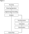
- an action plan can be selected. Besides just reporting the overall outcome of the evaluation it is further possible to pass further instructions or advice back to the device or another person/operator.
- Such instructions in the action plan may for instance comprise the advice of increase or lower the detergent concentration, raise or lower the temperature or process time, use a different detergent, control or change water quality, i.e. hardness and so on.
- Non-limiting examples of chemical test strips include those that are able to test for presence or concentration of tensides, dissolved calcium, acidity (i.e., pH), concentration of total hardness, chloride concentration, total residual chloride, free chloride residual, ortho-phosphate, m-alkalinity, and p-alkalinity.
- the chemical test strips are able to test for the presence and/or concentration of one or more treatment chemicals.
- Non-limiting examples of such test strips include those that test for the presence and/or concentration of an anionic, non-ionic or cationic tenside, enzymes, corrosion inhibitor, polymers, a biocide, and combinations thereof.
- the reaction zone is removed, e.g.
- the chemical test strip may also comprise a chemical test strip receptacle.
- the receptacle is a physical mean for placing the test strip securely within the recording process step.
- the receptacle also forms at least a part of an imaging chamber in order to provide uniformity in lighting and distance between the imaging device and the chemical test strip during imaging of the reactive zone.
- the receptacle further enhances the read-out stability of the test strip.
- the image is transmitted via a network, such as a cellular network or the Internet from the image device.
- the image device may provide also image analyzing software including a user interface in the form of an "app" or the like.
- the app may perform one or more of the following functions: enable storage of data and/or analysis thereof, upload data and/or analysis thereof to a central server or other specified location, provide "geo- tagging" of data and/or analysis thereof, and recommend a plan of action (as described herein).
- the app may generate reports that illustrate, describe, and/or summarize the data and/or analysis thereof.
- the app may perform and report statistical analysis calculations related to the data and/or analysis thereof.
- the test strip may comprise additional lines in the form of a geometrical body, wherein the geometrical body is selected from the group consisting of parallelogram, hexagon or circle, and the surface area ratio of reactive zone to total surface area within the geometrical body is larger or equal 0.7 and smaller or equal to 0.95. It has been found useful, that not the complete test strip surface is used for the chemical indicator. The remaining surface can be used for image calibration and, as already explained, the image evaluation routine is more stable if several areas are present, divided by areas wherein no reactive zone are present. In a further example embodiment, the single reactive zones may be separated by one or two zones of the same dimension comprising no reactive zones and no indicator. This set-up may further be advantageous for image recognition purposes. It is also within the meaning of the disclosure that above given ratio is larger or equal 0.7 and smaller or equal to 0.95.
- the size of the image may be scaled with respect to the size of reference pictures or data omitted in cases where not the indicator area or only a small part thereof was imaged.
- step 6 the black and white pixels are counted and for instance based on the pixel ratio a result is calculated, wherein the number of black and white pixels of the test strip image data after the cleaning process are counted and the counting result is compared to the quantitative evaluation result of the test strip prior to the cleaning process.
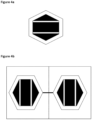
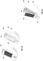
- FIG. 3b depicts a similar test indicator setup as displayed in figure 3a with the difference, that two test strips are attached together. Therefore, it is for instance possible to monitor the same spot in a washing machine, being subject to a cleaning liquid from two different sides by bending the strip in the middle portion. In addition, it is possible to use the two readouts of the test strips for comparison purposes.
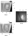
- FIG. 5a and 5b exhibit two images of the same test strip after a washing cycle and after performing the image transformation routine.
- the original test strip's image comprise three blue indicator areas in each hexagon and after the cleaning process two of the indicator areas are washed off.
- the middle indicator strip areas exhibit a faded blue color, which could be better discriminated in the figure 5b .
- the better discrimination is based on a luminescence color transformation and an adaptive thresholding, whereas for figure 5a a discarded blue channel and a linear thresholding algorithm are used.
- FIG. 9 exhibits a comparison of two evaluation routines for the same cleaning process.
- Both figures A and B display the result for a cleaning process with a water hardness of 14 and a detergent dosage of 0.5 %.
- the left picture (A) is calculated with a discarded blue channel and only a linear threshold algorithm.
- the overall routine results in a reading of only 29 % (given as the ratio of black to white pixels).
- FIG. 9 B displays the result using a routine according to the disclosure (inter alia including luminescence transformation and adaptive thresholding). Contrary to the other evaluation routine the outcome here is 46 %.
- the overall standard deviation by monitoring the same process is much smaller by using the example routine.
- test strips comprising a blue color indicator and a double sided set-up as depicted in FIG. 4 .
- FIG. 10 shows a photograph of an example imaging box 100 that may be used for image capture of a chemical test strip using an example mobile device 106.
- Mobile device 106 includes a power cable 102 and a user interface 104 that displays results of the cleaning assessment.
- FIG. 11 shows a photograph of an example imaging box 100 having an example mobile device 106 docked thereto, example chemical test strips 110, 120, and 122, and example chemical test strip holders 112.
- Test strip slot 114 is configured to receive and hold an unfolded test strip in a substantially flat position so that the position of test strips is consistent during image capture.
- test strip slot 114 is configured to receive and hold an unfolded test strip in a fixed position with respect to a mobile device camera when the mobile device is docked into the imaging box as shown in FIGS. 10 and 11 .
- Receptacle 108 is further configured to receive and hold a properly docked mobile device 106 in a consistent and fixed position relative to the position of the test strip when properly loaded into the test strip slot 114.
- Mobile device 106 includes a user interface 104 configured to display the results of the cleaning assessment.
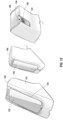
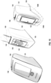
- FIG. 12 shows two front perspective views and a back perspective view of an example imaging box 130.
- Housing 131 of imagining box 130 includes a receptacle 133 configured to receive and hold a mobile device 132 (such as a smart phone or tablet computer) in a consistent and fixed position during image capture.
- Housing 131 of imaging box 130 further includes a test strip slot 134 configured to receive and hold a test strip and/or test strip holder in a fixed position during image capture. The test strip is loaded into slot 134 with the indicator area facing the interior cavity of housing 131.
- Housing 131 further includes an imaging aperture 135 through which an image of the indicator area of a test strip loaded into test strip slot 134 may be captured by a mobile device 132 as described herein.
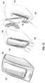
- FIG. 14 shows another example imaging box 140 and docking of an example mobile device 142 to the imaging box 140.
- the housing 141 of imaging box 140 includes cable management apertures 146A and 146B sized to receive a power cable of mobile device 142 when mobile device 142 is properly docked onto imagine box 140.
- Receptacle 148 of housing 141 also includes a camera aperture 145 and a light source aperture 143. Camera aperture 145 and light source 143 are configured to align with a camera lens and flash , respectively, on a mobile device, such as mobile device 142. If different type of mobile device is used, the camera and/or light source apertures 145, 143 may be located in a different position within receptacle 148.
- Camera aperture 145 is further configured to align with respect to an imaging aperture on a back surface of housing 141 (see, e.g., FIG. 12 ) such that an image of the indicator area on a test strip may be captured by the mobile device camera through the camera aperture 145.
- FIG. 15 shows another example imaging box 150 and docking of an example mobile device 152 to the imaging box 150.
- the housing 151 of imaging box 150 includes cable management apertures 156A and 156B sized to receive a power cable of mobile device 152 when mobile device 152 is properly docked onto imagine box 150.
- Housing 151 of imaging box 150 includes a slot 158 configured to receive and hold a mobile device 152.
- Housing 151 further includes a display aperture 155 on the front surface of the housing 151 sized to expose at least the touch screen display portion 153 of mobile device 152 accessible to a user.
- the housing 151 also includes a camera aperture 145 and a light source aperture 143 within slot 158 that are configured to align with a camera lens and flash, respectively, on a mobile device, such as mobile device 152.
- FIG. 16 show front perspective views of an example mobile devices 132, 142, and 152, docked to the example imaging boxes of FIG. 13 , 14 , and 15 , respectively.
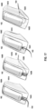
- FIG. 17 show front perspective views of an example mobile device 162 docked to additional example imaging boxes 160A-160D, each of which includes a different cable management technique.
- Housing 161A of imaging box 160A for example, includes a cable slot 162A sized to receive a power cable 164 of a mobile device.
- Housing 161B of imaging box 160B for example, includes a cable slot/aperture(s) 162B sized to receive a power cable 164 of a mobile device.
- Housing 161C of imaging box 160C for example, includes a cable aperture/slot 162C sized to receive a power cable 164 of a mobile device.
- Housing 161D of imaging box 160D for example, includes a cable slot(s) 162D sized to receive a power cable 164 of a mobile device
- FIG. 18 show views of six different example chemical test strip slots 172A-172F in the housings 171A-171F of example imaging boxes 170A-170F, respectively.
- Chemical test strips 173A-173F are positioned within chemical test strip slots 172A-172F, respectively, with the indicator area(s) of the test strip 1713A-173F facing the interior cavity of the respective imaging box 170A-170F.
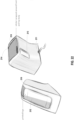
- FIG. 19 show perspective views of an example imaging box 180 configured to receive a mobile device 182 and an example light covering sticker 184.
- light covering sticker 184 covers the device receiving receptacle 186 and a top surface of housing 181.
- Light covering sticker prevents light from showing through the housing 181 of imaging box 180 when the flash of mobile device 182 is activated during image capture of the indicator area of a chemical test strip. This may help prevent light coming through housing 181 from affecting the lighting conditions during the image capture process, and thus the quality of the resulting image.
- FIG. 20 show perspective views of an example imaging box 190 and another example light covering sticker 194.
- light covering sticker 194 covers only the top surface of imaging box 190.
- Light covering sticker 194 prevents light from showing through the top surface of housing 191 of imaging box 190 when the flash of mobile device 192 is activated during image capture of the indicator area of a chemical test strip 193. This may help prevent light coming through housing 191 from affecting the lighting conditions during the image capture process, and thus the quality of the resulting image.
- FIG. 21 show perspective views of an example imaging box 200 and another example light covering sticker 204.
- light covering sticker 204 covers the top and back surfaces of imaging box 200.
- Light covering sticker 204 prevents light from showing through the top and back surfaces of housing 201 of imaging box 200 when the flash of mobile device 212 is activated during image capture of the indicator area of a chemical test strip 203. This may help prevent light coming through housing 201 from affecting the lighting conditions during the image capture process, and thus the quality of the resulting image.
- FIG. 22 show perspective views of an example imaging box 210 and another example light covering sticker 214.
- light covering sticker 214 covers the device receiving receptacle and a top surface of housing 211.
- Light covering sticker prevents light from showing through the housing 211 of imaging box 210 when the flash of mobile device 212 is activated during image capture of the indicator area of a chemical test strip. This may help prevent light coming through housing 211 from affecting the lighting conditions during the image capture process, and thus the quality of the resulting image.
- FIG. 23 show perspective views of an example imaging box 220 and another example light covering sticker 224.
- light covering sticker 224 covers the device receiving receptacle, a top surface of housing 221, and a back surface of housing 221.
- Light covering sticker prevents light from showing through the front, top and back surfaces of housing 221 of imaging box 220 when the flash of mobile device 222 is activated during image capture of the indicator area of a chemical test strip. This may help prevent light coming through housing 221 from affecting the lighting conditions during the image capture process, and thus the quality of the resulting image.
- FIG. 24 is a photograph of another example imaging box 230 having a housing 231 forming a cavity 236, an integrated light source 234 inside the cavity 236 of the imaging box 230, and an example mobile device 232 docked thereto.
- FIG. 25 shows a perspective and a cross-sectional view of an imaging box 240 including a housing 241 having a substantially square cross-section and including a substantially flat diffuser rib 244 in the interior cavity of housing 241.
- Housing 241 includes a slanted top surface and sidewalls 245 forming an open base portion through which the interior cavity 246 of imaging box 240 may be accessed.
- Imaging box 240 is configured to receive a mobile device 242 on slanted top surface of the housing 241.
- a camera aperture 245 and a flash aperture 247 are configured to align with a camera lens and a flash of mobile device 242.
- Diffuser rib 244 serves to scatter and/or diffusely reflect the relatively more concentrated light directed into the cavity 246 from the camera flash, thus helping to prevent glare or artifacts in the test strip image due to unsuitable or unfavorable light-conditions, e.g. obtained under too much light or with undesirable light reflections.
- FIG. 26 shows a perspective and a cross-sectional view of an imaging box 250 an associated mobile device 252.
- Imaging box 250 includes a housing 251 and an interior cavity 256 formed by interior rounded sidewalls 258. Housing further includes a camera aperture 255 and a flash aperture 257.
- Housing 251 further includes including a curved diffuser rib 254 positioned proximate to the flash aperture on the interior surface of cavity 258. Curved diffuser rib 254 serves to scatter and/or diffusely reflect the relatively more concentrated light directed into the cavity 256 from the camera flash.
- the curved shape of diffuser rib 254 may help to diffusely reflect the incident light more uniformly around the cavity 256.
- curved interior surfaces 258 may further help to diffusely reflect or scatter the incident light to help prevent glare, bright spots, or artifacts in the captured image.
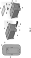
- FIG. 27 shows a top view of an example imaging box 260 with an example mobile device 262 docked thereto, a side perspective view of the example imaging box 260 showing a test strip 264 in a test strip slot holder 266 being inserted into a test strip slot 263, and an exploded view of the imaging box 260 showing a removable diffuser insert 268.
- a top surface of housing 261 includes an insert aperture 269 sized to receive the removable diffuser insert 268.
- Removable diffuser insert 268 includes a camera aperture 265A, a flash aperture 265B, and a diffusing rib 267.
- FIG. 28 shows five different imaging box diffuser inserts 274A-274E with differently shaped diffusing ribs: a half cylinder diffuser 278A, a large arc diffuser 278B, a small arc diffuser 278C, a dome 45-degree diffuser 278D, and a dome perpendicular diffuser 278E, respectively.
- Each diffuser insert 274A-274E includes a camera aperture 272 and a flash aperture 276.
- the diffuser ribs 278A-278E are positioned proximate to flash apertures 276 on the respective diffuser insert 274A-274E.
- diffuser ribs 278A-278E serve to diffusely reflect or scatter light incident into an interior cavity of an imaging box from a flash of a mobile device in such a way as to reduce or eliminate glare, artifacts, or bright spots in images of one or more test strips taken with a mobile device docked with the imaging box.
- FIG. 28 also shows photographs of the interiors 279A-279E of a light box using the respective diffuser inserts 274A-274E.
- FIG. 29 shows an example imaging box 280 and an example mobile device 282 docked thereto, and an example imaging box 280 alone and showing a camera aperture 286 and a flash aperture 284 in the imaging box housing 281 configured to correspond to the position of a mobile device camera lens and a mobile device flash.
- FIG. 30 shows an example imaging box 280 showing the docking process for an example mobile device 282.
- box 280 includes a housing 281 having a receptacle 288 configured to receive a mobile device 282.
- Housing 281 further includes cable slot 287 sized to receive a power cable of mobile device 282.
- Housing 281 further includes camera aperture 286 and flash aperture 284 configured to correspond to the position of a mobile device camera lens and a mobile device flash, respectively.
- FIG. 31 shows an example test strip slot 294 in a housing 291 of an example imaging box 290.
- Test strip slot 294 is sized to receive a test strip 293 with the test strip indicator facing the interior cavity of the housing 291 during the test strip image capture process as described herein.
- Housing further includes an imaging aperture 295 aligned with test strip slot 294 such that an image of the indicator area of the test strip 293 may be captured by the mobile device camera through the camera aperture.
- FIG. 32 shows an example of cable management apertures 294A and 294B for an example imaging box 290.
- FIG. 32 also shows a back view of imaging box 290 in which a test strip 293 is viewable in a test strip slot 294.
- FIG. 33 shows an example test strip slot 315 in a housing 311 of an example imaging box 310.
- FIG. 34 shows an example of cable management slot 314 in a housing 311 of an example imaging box 310.
- the slot 314 is sized to receive a power cable 314 of a mobile device 312.
- FIG. 35 shows a bottom cross-sectional perspective view of an example imaging box 320 and a mobile device 322.
- Imaging box 320 includes a housing 321 defining an interior cavity 326 in which a test strip 329 is positioned for image capture in a test strip slot 328.
- the interior walls of housing 312 include an interior dividing rib 324. Dividing rib 324 serves to make the interior cavity 323 in which the imaging takes place smaller (as opposed to the entire interior cavity of the housing).
- FIG. 36 shows a cross-sectional view of an example imaging box 320 showing a curved diffuser rib 326 positioned proximate to camera aperture 327 and an interior housing dividing rib 324.
- Dividing rib 324 is curved to help scatter and/or diffusely reflect light incident through flash aperture 325, thus helping to reduce glare, artifacts and/or bright spots in any images captured using imaging box 320.
- FIG. 37 shows a cross-sectional view of an example imaging box 320 having a chemical test strip 329 inserted therein for image capture, and showing an example curved diffuser rib 326 and an interior housing dividing rib 324.
- FIG. 37 further shows an example light ray entering the interior cavity of imaging box 380 through flash aperture 325, incident upon test strip 329, and exiting through camera aperture 327. Light rays directed as shown in FIG.
- FIG. 38 shows a cross-sectional view of an example imaging box 330 having a chemical test strip 331 inserted therein for image capture, and showing two diffuser ribs 335, 336 and an interior housing dividing rib 334.
- Imaging box 330 further includes an interior cavity 333.
- Imaging box 330 further includes a transverse reflective surface 337 that may additionally serve to diffusely reflect and/or scatter light incident into cavity 333.
- FIG. 39 shows a cross-sectional view of an example imaging box 340 having a chemical test strip 341 inserted therein for image capture, and showing two diffuser ribs 345, 346, and an interior housing dividing rib 344.
- Imaging box 340 further includes an interior cavity 343.
- Imaging box 340 further includes a transverse reflective surface 347 that may additionally serve to diffusely reflect and/or scatter light incident into cavity 343.
- FIG. 40 shows a cross-sectional view of an example imaging box 350 having two diffuser ribs 355, 356, and an interior housing dividing rib 354.
- Imaging box 350 also includes an interior cavity 357 and a camera aperture 357.
- FIG. 41 shows a block diagram of a system 200 for assessing the performance of a cleaning process.
- the system includes an imaging box 202 for use in an image capture procedure for the performance assessment of a cleaning process.
- the system 200 further includes a cleaning assessment application configured to be executed on a mobile computing device 210.
- the system 200 further includes a computing device 260 configured to receive and evaluate the digital image of the chemical test strip and generate an assessment of the performance of the cleaning process.
- the imaging box 202 includes a housing defined by a front surface and a back surface and forming an interior cavity when the housing is placed on a substantially flat surface, the front surface having a receptacle configured to receive a mobile device 210.
- the front surface further including at least one camera aperture configured to correspond to the position of a camera lens of the mobile device when the mobile device is received in the receptacle.
- the back surface includes a test strip slot configured to receive and hold a chemical test strip comprising a carrier and an indicator means in a substantially flat position.
- the back surface further includes a test strip aperture configured to correspond to the position of a chemical test strip 204 when received into the test strip slot, such that an image of the chemical test strip may be captured by the camera of the mobile device when the chemical test strip 204 is inserted into the test strip slot such that the indicator means is facing the interior cavity of the housing.
- the mobile device 210 includes one or more processors, a cleaning assessment application configured to be executed on the one or more processors, a camera, a flash/light source, a user interface/display, and a memory/data storage.
- the cleaning application is configured to receive and display the assessment of the performance of the cleaning process on the user interface of the mobile computing device 210.
- the cleaning assessment application may be further configured to guide a user through a chemical test strip image capture procedure.
- the steps of the procedure may be displayed on the graphical user interface/display of the mobile device 210.
- the computing device 260 may be located remotely with respect to the mobile device.
- the mobile device 210 and the computing device 260 may communicate through one or more networks 250, or through any suitable form of data communication (e.g., wired or wireless network, short-range wireless communication such as Near Field Communication or Bluetooth, etc.).
- the networks and/or the communication may be wired or wireless.
- the networks may include, for example, one or more local area network(s) (LAN), wide area network(s) (WAN), virtual private network(s) (VPN), a wireless or Wi-Fi network, a cellular network, a satellite communication network, or any other means of electronic communication.
- the computing device 260 may be configured to evaluate the digital image of the chemical test strip according to the image processing techniques described herein.
- cleaning assessment/image processing instructions on computing device 260 may include instructions that cause the one or more processors to execute the image processing techniques described herein.
- the term “or” may be interrupted as “and/or” where context does not dictate otherwise. Additionally, while phrases such as “one or more” or “at least one” or the like may have been used in some instances but not others, those instances where such language was not used may be interpreted to have such a meaning implied where context does not dictate otherwise.
- the functions described may be implemented in hardware, software, firmware, or any combination thereof. If implemented in software, the functions may be stored on or transmitted over, as one or more instructions or code, a computer-readable device or medium and executed by a hardware-based processing unit.
- Computer-readable media may include computer-readable storage media, which corresponds to a tangible medium such as data storage media, or communication media including any medium that facilitates transfer of a computer program from one place to another, e.g., according to a communication protocol.
- Computer-readable media generally may correspond to non-transitory tangible computer-readable storage media.
- Data storage media may be any available media that can be accessed by one or more computers or one or more processors to retrieve instructions, code and/or data structures for implementation of the techniques described in this disclosure.
- a computer program product may include a computer-readable medium.
- such computer-readable storage media can comprise RAM, ROM, EEPROM, CD-ROM or other optical disk storage, magnetic disk storage, or other magnetic storage devices, flash memory, or any other medium that can be used to store desired program code in the form of instructions or data structures and that can be accessed by a computer.
- any connection is properly termed a computer-readable medium.
- a computer-readable medium For example, if instructions are transmitted from a website, server, or other remote source using a coaxial cable, fiber optic cable, twisted pair, digital subscriber line (DSL), or wireless technologies such as infrared, radio, and microwave, then the coaxial cable, fiber optic cable, twisted pair, DSL, or wireless technologies such as infrared, radio, and microwave are included in the definition of medium.
- DSL digital subscriber line
- Disk and disc includes compact disc (CD), laser disc, optical disc, digital versatile disc (DVD), floppy disk and Blu-ray disc, where disks usually reproduce data magnetically, while discs reproduce data optically with lasers. Combinations of the above should also be included within the scope of computer-readable media.
- processors such as one or more digital signal processors (DSPs), general purpose microprocessors, application specific integrated circuits (ASICs), field programmable logic arrays (FPGAs), or other equivalent integrated or discrete logic circuitry.
- DSPs digital signal processors
- ASICs application specific integrated circuits
- FPGAs field programmable logic arrays
- processors may refer to any of the foregoing structure or any other structure suitable for implementation of the techniques described.
- the functionality described may be provided within dedicated hardware and/or software modules. Also, the techniques could be fully implemented in one or more circuits or logic elements.
- the techniques of this disclosure may be implemented in a wide variety of devices or apparatuses, including a wireless handset, an integrated circuit (IC) or a set of ICs (e.g., a chip set).
- IC integrated circuit
- a set of ICs e.g., a chip set.
- Various components, modules, or units are described in this disclosure to emphasize functional aspects of devices configured to perform the disclosed techniques, but do not necessarily require realization by different hardware units. Rather, as described above, various units may be combined in a hardware unit or provided by a collection of interoperating hardware units, including one or more processors as described above, in conjunction with suitable software and/or firmware.
Landscapes
- Health & Medical Sciences (AREA)
- Engineering & Computer Science (AREA)
- Life Sciences & Earth Sciences (AREA)
- Physics & Mathematics (AREA)
- General Health & Medical Sciences (AREA)
- General Physics & Mathematics (AREA)
- Chemical & Material Sciences (AREA)
- Animal Behavior & Ethology (AREA)
- Immunology (AREA)
- Veterinary Medicine (AREA)
- Pathology (AREA)
- Epidemiology (AREA)
- Public Health (AREA)
- Analytical Chemistry (AREA)
- Biochemistry (AREA)
- Signal Processing (AREA)
- Multimedia (AREA)
- Chemical Kinetics & Catalysis (AREA)
- Plasma & Fusion (AREA)
- Quality & Reliability (AREA)
- Computer Vision & Pattern Recognition (AREA)
- Theoretical Computer Science (AREA)
- Molecular Biology (AREA)
- Investigating Materials By The Use Of Optical Means Adapted For Particular Applications (AREA)
- General Factory Administration (AREA)
- Management, Administration, Business Operations System, And Electronic Commerce (AREA)
Priority Applications (1)
| Application Number | Priority Date | Filing Date | Title |
|---|---|---|---|
| EP19182688.2A EP3570013B1 (en) | 2017-10-03 | 2018-10-01 | Methods and system for performance assessment of cleaning operations |
Applications Claiming Priority (1)
| Application Number | Priority Date | Filing Date | Title |
|---|---|---|---|
| US201762567687P | 2017-10-03 | 2017-10-03 |
Related Child Applications (2)
| Application Number | Title | Priority Date | Filing Date |
|---|---|---|---|
| EP19182688.2A Division-Into EP3570013B1 (en) | 2017-10-03 | 2018-10-01 | Methods and system for performance assessment of cleaning operations |
| EP19182688.2A Division EP3570013B1 (en) | 2017-10-03 | 2018-10-01 | Methods and system for performance assessment of cleaning operations |
Publications (4)
| Publication Number | Publication Date |
|---|---|
| EP3467482A2 EP3467482A2 (en) | 2019-04-10 |
| EP3467482A3 EP3467482A3 (en) | 2019-06-05 |
| EP3467482B1 true EP3467482B1 (en) | 2023-10-18 |
| EP3467482C0 EP3467482C0 (en) | 2023-10-18 |
Family
ID=63921479
Family Applications (2)
| Application Number | Title | Priority Date | Filing Date |
|---|---|---|---|
| EP18197940.2A Active EP3467482B1 (en) | 2017-10-03 | 2018-10-01 | Methods and system for performance assessment of cleaning operations |
| EP19182688.2A Active EP3570013B1 (en) | 2017-10-03 | 2018-10-01 | Methods and system for performance assessment of cleaning operations |
Family Applications After (1)
| Application Number | Title | Priority Date | Filing Date |
|---|---|---|---|
| EP19182688.2A Active EP3570013B1 (en) | 2017-10-03 | 2018-10-01 | Methods and system for performance assessment of cleaning operations |
Country Status (3)
| Country | Link |
|---|---|
| US (5) | US10762617B2 (pl) |
| EP (2) | EP3467482B1 (pl) |
| PL (1) | PL3467482T3 (pl) |
Families Citing this family (16)
| Publication number | Priority date | Publication date | Assignee | Title |
|---|---|---|---|---|
| EP3467482B1 (en) | 2017-10-03 | 2023-10-18 | Ecolab USA Inc. | Methods and system for performance assessment of cleaning operations |
| US11087153B2 (en) * | 2018-10-31 | 2021-08-10 | Cognizant Technology Solutions India Pvt. Ltd. | Traffic light recognition system and method |
| US11398309B2 (en) | 2018-11-27 | 2022-07-26 | Alarm.Com Incorporated | Automated surface sterilization techniques |
| KR102746107B1 (ko) * | 2019-01-08 | 2024-12-23 | 주식회사 엘지에너지솔루션 | 신규한 세정액 평가방법 |
| CA3133216A1 (en) * | 2019-03-22 | 2020-10-01 | Advanced Sterilization Products, Inc. | Cleaning indicator and method of using same |
| CA3161298A1 (en) | 2019-12-03 | 2021-06-10 | Ecolab Usa Inc. | Verification of cleaning process efficacy |
| CN111024694A (zh) * | 2019-12-10 | 2020-04-17 | 上海发那科机器人有限公司 | 一种鸵鸟毛擦净设备对车身擦净效果的检测系统及方法 |
| JP7741821B2 (ja) | 2020-05-29 | 2025-09-18 | エコラボ ユーエスエー インコーポレイティド | 短縮されたサイクル時間を使用する自動洗浄機処理 |
| US20230266232A1 (en) * | 2020-09-04 | 2023-08-24 | 3M Innovative Properties Company | Chromatographic reader devices for biodetection |
| US11631279B2 (en) * | 2020-09-24 | 2023-04-18 | Alarm.Com Incorporated | Smart cleaning system |
| CA3196819A1 (en) | 2020-09-24 | 2022-03-31 | Alarm.Com Incorporated | Self-cleaning environment |
| WO2022066211A1 (en) | 2020-09-25 | 2022-03-31 | Ecolab Usa Inc. | Machine learning classification or scoring of cleaning outcomes in cleaning machines |
| EP4221555A1 (en) | 2020-10-02 | 2023-08-09 | Ecolab USA Inc. | Monitoring and control of thermal sanitization in automated cleaning machines |
| US11102381B1 (en) | 2021-01-05 | 2021-08-24 | Board Of Regents, The University Of Texas System Clearcam Inc. | Methods, systems and controllers for facilitating cleaning of an imaging element of an imaging device |
| GB202103261D0 (en) * | 2021-03-09 | 2021-04-21 | Intercede Ventures Ltd | System for detecting and assessing a sanitising process |
| US12572119B2 (en) | 2022-05-19 | 2026-03-10 | Ecolab Usa Inc. | Acoustic monitoring for detection of anomalous operation of cleaning machines |
Citations (2)
| Publication number | Priority date | Publication date | Assignee | Title |
|---|---|---|---|---|
| DE102010033016A1 (de) * | 2010-07-31 | 2012-02-02 | Robert Simmoteit | Anschmutzungsfläche und Analysenmethode |
| US20160171690A1 (en) * | 2014-05-12 | 2016-06-16 | Ownhealth Ltd. | Method and system for automated visual analysis of a dipstick using standard user equipment |
Family Cites Families (61)
| Publication number | Priority date | Publication date | Assignee | Title |
|---|---|---|---|---|
| JP3143995B2 (ja) | 1991-10-31 | 2001-03-07 | 松下電器産業株式会社 | 食器洗い機 |
| US5923432A (en) | 1997-12-18 | 1999-07-13 | Steris Corporation | Cleaning efficacy real time indicator |
| US6488890B1 (en) | 1999-08-05 | 2002-12-03 | 3M Innovative Properties Company | Machine readable sterilization indicator for monitoring articles to be sterilized |
| US6615850B1 (en) | 1999-09-10 | 2003-09-09 | General Electric Company | Dishwasher sanitation cycle |
| US6463940B1 (en) | 2000-04-13 | 2002-10-15 | Ecolab Inc. | Smart rack and machine system |
| US6628829B1 (en) | 2000-08-08 | 2003-09-30 | Richard Jeffrey Chasen | Method and system for matching a surface color |
| US7803322B2 (en) * | 2002-08-14 | 2010-09-28 | Detekt Biomedical, L.L.C. | Universal optical imaging and processing system |
| US7437213B2 (en) | 2002-11-04 | 2008-10-14 | Ecolab Inc. | Monitoring performance of a warewasher |
| US8012421B2 (en) | 2003-06-24 | 2011-09-06 | Ecolab Inc. | Concentration monitor |
| US20140041688A1 (en) | 2004-11-19 | 2014-02-13 | Meiko Maschinenbau Gmbh & Co Kg | Method for assessing and guaranteeing a thermal hygiene effect |
| WO2006097294A1 (de) | 2005-03-16 | 2006-09-21 | Meiko Maschinenbau Gmbh & Co. Kg | Verfahren zur beurteilung und sicherstellung der thermischen hygienewirkung in einer mehrtankgeschirrspülmaschine |
| US7563329B2 (en) | 2005-03-31 | 2009-07-21 | Ethicon Inc. | Monitoring of cleaning process |
| CA2601720C (en) | 2005-04-01 | 2014-08-12 | Advanced Medical Products Gmbh | Body fluid testing component for analyte detection |
| JP2007212434A (ja) | 2006-01-16 | 2007-08-23 | Sakura Color Prod Corp | 洗浄・消毒確認用インジケータ及び洗浄・消毒確認方法 |
| ES2423995T3 (es) | 2006-08-10 | 2013-09-26 | Electrolux Home Products Corporation N.V. | Electrodoméstico con detector contextual y funcionamiento dependiente del contexto |
| US20170023542A1 (en) * | 2015-07-26 | 2017-01-26 | Naishu Wang | Smartphone dock and diagnostic-test reader plus related methods |
| US8150115B2 (en) * | 2007-04-18 | 2012-04-03 | Iris International, Inc. | Chemistry strip reader and method |
| USD605588S1 (en) | 2008-06-12 | 2009-12-08 | Sanyo Electric Co., Ltd. | Battery charger for a controller |
| DE102008042290B4 (de) | 2008-09-23 | 2021-05-12 | BSH Hausgeräte GmbH | Verfahren zum Betreiben eines Hausgeräts und Hausgerät mit einer Eingabeeinheit |
| ES2414654T3 (es) | 2009-02-05 | 2013-07-22 | Danja Kaiser | Indicador de limpieza y cuerpo de test para el ensayo de procesos de limpieza |
| US8528228B2 (en) | 2009-02-19 | 2013-09-10 | Whirlpool Corporation | Laundry treating appliance with drying rack detection based on imaging data |
| US20100254581A1 (en) | 2009-04-07 | 2010-10-07 | Reveal Sciences, Llc | Device, method, and apparatus for biological testing with a mobile device |
| WO2011048575A2 (en) | 2009-10-23 | 2011-04-28 | Ecolab Inc. | Optical processing to control a washing apparatus |
| GB201000835D0 (en) | 2010-01-19 | 2010-03-03 | Akzo Nobel Coatings Int Bv | Method and system for determining colour from an image |
| US9743820B2 (en) | 2010-02-26 | 2017-08-29 | Whirlpool Corporation | User interface for dishwashing cycle optimization |
| US8696827B2 (en) | 2010-12-01 | 2014-04-15 | Whirlpool Corporation | Dishwasher with imaging device for measuring load characteristics and a method for controlling same |
| EP2497404A1 (en) | 2011-03-10 | 2012-09-12 | Bonferraro S.p.A. | Cleaning cycle for diswasher with device for recycling the rinse water |
| USD677669S1 (en) | 2011-10-27 | 2013-03-12 | Jiyu Liu | Portable support for electronic devices |
| CA3151127C (en) | 2011-12-13 | 2026-04-07 | Ecolab Usa Inc. | Deliming dishmachine |
| US20140218385A1 (en) | 2012-09-10 | 2014-08-07 | Applitools Ltd. | System and method for visual segmentation of application screenshots |
| USD699246S1 (en) | 2012-11-14 | 2014-02-11 | John Frederick Ringlein | Electronic device holder with pencil cup |
| US9329159B2 (en) | 2013-03-08 | 2016-05-03 | Ecolab Usa Inc. | Methods and systems for analyzing a liquid medium |
| TWD161839S (zh) | 2013-08-02 | 2014-07-21 | 富士康(香港)有限公司 | 電子裝置之多功能包裝盒 |
| DE102013218448A1 (de) | 2013-09-13 | 2015-03-19 | Schülke & Mayr GmbH | Methode zur Bestimmung der Reinigungsleistung von Formulierungen |
| JP6158668B2 (ja) | 2013-09-30 | 2017-07-05 | 株式会社Pfu | 画像読取装置 |
| CN103678980A (zh) | 2013-12-06 | 2014-03-26 | 北京奇虎科技有限公司 | 智能终端的安全保护方法及其装置 |
| US9658217B2 (en) | 2014-02-17 | 2017-05-23 | Ixensor Co., Ltd | Measuring physical and biochemical parameters with mobile devices |
| CA2940894A1 (en) | 2014-02-27 | 2015-09-03 | Walter Surface Technologies Inc. | Industrial cleanliness measurement methodology |
| USD715284S1 (en) | 2014-04-16 | 2014-10-14 | Denso International America, Inc. | Mobile device cradle |
| JP5860947B1 (ja) | 2014-11-12 | 2016-02-16 | 株式会社Pfu | 画像読取装置 |
| USD795323S1 (en) | 2015-03-16 | 2017-08-22 | Tripled Experience Ltd. | Apparatus for capturing images of gemstones |
| EP3088593A1 (en) | 2015-04-27 | 2016-11-02 | The Procter and Gamble Company | Method for improving washing machine performance |
| EP3313272A4 (en) * | 2015-06-23 | 2019-02-20 | Metaoptima Technology Inc. | APPARATUS FOR IMAGING THE SKIN |
| USD788778S1 (en) | 2015-08-03 | 2017-06-06 | Intel Corporation | Cooling docking station |
| USD768138S1 (en) | 2015-08-14 | 2016-10-04 | Kenneth R. Malsan | Dual angle display stand for portable electronic devices |
| WO2017056002A1 (en) * | 2015-09-29 | 2017-04-06 | Ascensia Diabetes Care Holdings Ag | Method and system of using a mobile device for analyte detection |
| US20180330338A1 (en) | 2015-11-12 | 2018-11-15 | Diversey, Inc. | Predictive maintenance |
| USD808947S1 (en) | 2015-12-22 | 2018-01-30 | Pfu Limited | Accessory for a smartphone camera |
| US10514339B2 (en) * | 2016-08-30 | 2019-12-24 | Htc Corporation | Test strip analyser having frame with movable support and test strip carrier |
| USD837180S1 (en) | 2017-05-17 | 2019-01-01 | Kovacorp | Communicator |
| CN107421918B (zh) | 2017-07-17 | 2019-12-17 | 佛山市顺德区美的洗涤电器制造有限公司 | 测量浊度的方法及装置、洗碗机、存储介质 |
| CN107485356B (zh) | 2017-09-01 | 2019-10-18 | 佛山市顺德区美的洗涤电器制造有限公司 | 洗碗机的洗涤控制方法和装置以及洗碗机 |
| CN107729816A (zh) | 2017-09-15 | 2018-02-23 | 珠海格力电器股份有限公司 | 洗涤模式的确定方法、装置、存储介质、处理器及洗碗机 |
| EP3467482B1 (en) | 2017-10-03 | 2023-10-18 | Ecolab USA Inc. | Methods and system for performance assessment of cleaning operations |
| USD872072S1 (en) | 2017-10-04 | 2020-01-07 | Ecolab Usa Inc. | Mounting stand for image capture using a mobile device |
| US10529219B2 (en) | 2017-11-10 | 2020-01-07 | Ecolab Usa Inc. | Hand hygiene compliance monitoring |
| US11158072B2 (en) | 2018-02-02 | 2021-10-26 | Dishcraft Robotics, Inc. | Intelligent dishwashing systems and methods |
| DE102018108775A1 (de) | 2018-04-13 | 2019-10-17 | Miele & Cie. Kg | Verfahren und Vorrichtung zum Bereitstellen einer Optimierungsempfehlung für einen Pflegevorgang in einem Pflegegerät |
| CN110367898B (zh) | 2019-07-31 | 2021-05-04 | 佛山市百斯特电器科技有限公司 | 一种清洗模式的确定方法及洗碗机 |
| CN114269217A (zh) | 2019-09-12 | 2022-04-01 | 埃科莱布美国股份有限公司 | 使用机器视觉控制清洁机器循环 |
| CA3161298A1 (en) | 2019-12-03 | 2021-06-10 | Ecolab Usa Inc. | Verification of cleaning process efficacy |
-
2018
- 2018-10-01 EP EP18197940.2A patent/EP3467482B1/en active Active
- 2018-10-01 PL PL18197940.2T patent/PL3467482T3/pl unknown
- 2018-10-01 US US16/148,628 patent/US10762617B2/en active Active
- 2018-10-01 EP EP19182688.2A patent/EP3570013B1/en active Active
-
2020
- 2020-08-07 US US16/987,868 patent/US11393083B2/en active Active
-
2022
- 2022-07-15 US US17/812,904 patent/US11803957B2/en active Active
-
2023
- 2023-10-30 US US18/497,625 patent/US12141957B2/en active Active
-
2024
- 2024-10-22 US US18/923,220 patent/US20250045902A1/en active Pending
Patent Citations (2)
| Publication number | Priority date | Publication date | Assignee | Title |
|---|---|---|---|---|
| DE102010033016A1 (de) * | 2010-07-31 | 2012-02-02 | Robert Simmoteit | Anschmutzungsfläche und Analysenmethode |
| US20160171690A1 (en) * | 2014-05-12 | 2016-06-16 | Ownhealth Ltd. | Method and system for automated visual analysis of a dipstick using standard user equipment |
Non-Patent Citations (1)
| Title |
|---|
| KUMAR GAURAV ET AL: "A Detailed Review of Feature Extraction in Image Processing Systems", 2014 FOURTH INTERNATIONAL CONFERENCE ON ADVANCED COMPUTING & COMMUNICATION TECHNOLOGIES, IEEE, 8 February 2014 (2014-02-08), pages 5 - 12, XP032584849, DOI: 10.1109/ACCT.2014.74 * |
Also Published As
| Publication number | Publication date |
|---|---|
| US12141957B2 (en) | 2024-11-12 |
| US10762617B2 (en) | 2020-09-01 |
| US20190102876A1 (en) | 2019-04-04 |
| EP3467482A2 (en) | 2019-04-10 |
| US20250045902A1 (en) | 2025-02-06 |
| US20220383486A1 (en) | 2022-12-01 |
| US20210019874A1 (en) | 2021-01-21 |
| EP3467482A3 (en) | 2019-06-05 |
| EP3570013A1 (en) | 2019-11-20 |
| US20240062357A1 (en) | 2024-02-22 |
| EP3467482C0 (en) | 2023-10-18 |
| PL3467482T3 (pl) | 2024-02-05 |
| US11393083B2 (en) | 2022-07-19 |
| EP3570013B1 (en) | 2026-02-18 |
| EP3570013C0 (en) | 2026-02-18 |
| US11803957B2 (en) | 2023-10-31 |
Similar Documents
| Publication | Publication Date | Title |
|---|---|---|
| US12141957B2 (en) | Methods and system for performance assessment of cleaning operations | |
| JP2023164793A (ja) | サンプル中の分析物検出用のモバイルデバイスのカメラの較正方法 | |
| CN1894702B (zh) | 生物生长板上的生物因子计数方法和系统 | |
| TW546754B (en) | On-the-fly automatic defect classification for substrates using signal attributes | |
| TW201924605A (zh) | 用於執行分析量測之方法及裝置 | |
| JP7716427B2 (ja) | 色基準カードの品質を評価する方法 | |
| AU2019284820A1 (en) | Method for evaluating a suitability of lighting conditions for detecting an analyte in a sample using a camera of a mobile device | |
| US20250200806A1 (en) | Method and devices for performing an analytical measurement | |
| JP7232900B2 (ja) | 画像処理基盤の水分及び光透過度測定システム、並びにこれを用いた水分及び光透過度測定方法 | |
| GB2598283A (en) | Method and apparatus for inspecting the surface of a transparent object | |
| CN111524102A (zh) | 一种液晶显示器的屏幕脏污检测方法及装置 | |
| EP3557528B1 (fr) | Systeme et procede d'analyse de dispositifs de test | |
| JP7592038B2 (ja) | 体液中の分析物の濃度を決定する方法 | |
| HK40085153A (en) | Method of evaluating the quality of a color reference card | |
| US10107686B1 (en) | Vision strip analyzer | |
| HK40038540A (en) | Method and devices for performing an analytical measurement | |
| CA3193927A1 (en) | Analysis system and method | |
| HK40031609B (zh) | 用於执行基於颜色形成反应的分析测量的方法和设备 | |
| JPH01231181A (ja) | 外観検査装置のための検査能力評価方法及び装置 | |
| JPH01245365A (ja) | 外観検査装置のための検査能力評価方法及び装置 |
Legal Events
| Date | Code | Title | Description |
|---|---|---|---|
| PUAI | Public reference made under article 153(3) epc to a published international application that has entered the european phase |
Free format text: ORIGINAL CODE: 0009012 |
|
| STAA | Information on the status of an ep patent application or granted ep patent |
Free format text: STATUS: THE APPLICATION HAS BEEN PUBLISHED |
|
| AK | Designated contracting states |
Kind code of ref document: A2 Designated state(s): AL AT BE BG CH CY CZ DE DK EE ES FI FR GB GR HR HU IE IS IT LI LT LU LV MC MK MT NL NO PL PT RO RS SE SI SK SM TR |
|
| AX | Request for extension of the european patent |
Extension state: BA ME |
|
| PUAL | Search report despatched |
Free format text: ORIGINAL CODE: 0009013 |
|
| AK | Designated contracting states |
Kind code of ref document: A3 Designated state(s): AL AT BE BG CH CY CZ DE DK EE ES FI FR GB GR HR HU IE IS IT LI LT LU LV MC MK MT NL NO PL PT RO RS SE SI SK SM TR |
|
| AX | Request for extension of the european patent |
Extension state: BA ME |
|
| RIC1 | Information provided on ipc code assigned before grant |
Ipc: G01N 21/84 20060101AFI20190429BHEP |
|
| STAA | Information on the status of an ep patent application or granted ep patent |
Free format text: STATUS: REQUEST FOR EXAMINATION WAS MADE |
|
| 17P | Request for examination filed |
Effective date: 20190627 |
|
| RBV | Designated contracting states (corrected) |
Designated state(s): AL AT BE BG CH CY CZ DE DK EE ES FI FR GB GR HR HU IE IS IT LI LT LU LV MC MK MT NL NO PL PT RO RS SE SI SK SM TR |
|
| STAA | Information on the status of an ep patent application or granted ep patent |
Free format text: STATUS: EXAMINATION IS IN PROGRESS |
|
| 17Q | First examination report despatched |
Effective date: 20200110 |
|
| GRAP | Despatch of communication of intention to grant a patent |
Free format text: ORIGINAL CODE: EPIDOSNIGR1 |
|
| STAA | Information on the status of an ep patent application or granted ep patent |
Free format text: STATUS: GRANT OF PATENT IS INTENDED |
|
| INTG | Intention to grant announced |
Effective date: 20230512 |
|
| GRAS | Grant fee paid |
Free format text: ORIGINAL CODE: EPIDOSNIGR3 |
|
| GRAA | (expected) grant |
Free format text: ORIGINAL CODE: 0009210 |
|
| STAA | Information on the status of an ep patent application or granted ep patent |
Free format text: STATUS: THE PATENT HAS BEEN GRANTED |
|
| AK | Designated contracting states |
Kind code of ref document: B1 Designated state(s): AL AT BE BG CH CY CZ DE DK EE ES FI FR GB GR HR HU IE IS IT LI LT LU LV MC MK MT NL NO PL PT RO RS SE SI SK SM TR |
|
| REG | Reference to a national code |
Ref country code: GB Ref legal event code: FG4D |
|
| REG | Reference to a national code |
Ref country code: CH Ref legal event code: EP |
|
| REG | Reference to a national code |
Ref country code: IE Ref legal event code: FG4D |
|
| REG | Reference to a national code |
Ref country code: DE Ref legal event code: R096 Ref document number: 602018059492 Country of ref document: DE |
|
| U01 | Request for unitary effect filed |
Effective date: 20231115 |
|
| U07 | Unitary effect registered |
Designated state(s): AT BE BG DE DK EE FI FR IT LT LU LV MT NL PT SE SI Effective date: 20231121 |
|
| PG25 | Lapsed in a contracting state [announced via postgrant information from national office to epo] |
Ref country code: GR Free format text: LAPSE BECAUSE OF FAILURE TO SUBMIT A TRANSLATION OF THE DESCRIPTION OR TO PAY THE FEE WITHIN THE PRESCRIBED TIME-LIMIT Effective date: 20240119 |
|
| PG25 | Lapsed in a contracting state [announced via postgrant information from national office to epo] |
Ref country code: IS Free format text: LAPSE BECAUSE OF FAILURE TO SUBMIT A TRANSLATION OF THE DESCRIPTION OR TO PAY THE FEE WITHIN THE PRESCRIBED TIME-LIMIT Effective date: 20240218 |
|
| PG25 | Lapsed in a contracting state [announced via postgrant information from national office to epo] |
Ref country code: ES Free format text: LAPSE BECAUSE OF FAILURE TO SUBMIT A TRANSLATION OF THE DESCRIPTION OR TO PAY THE FEE WITHIN THE PRESCRIBED TIME-LIMIT Effective date: 20231018 |
|
| PG25 | Lapsed in a contracting state [announced via postgrant information from national office to epo] |
Ref country code: IS Free format text: LAPSE BECAUSE OF FAILURE TO SUBMIT A TRANSLATION OF THE DESCRIPTION OR TO PAY THE FEE WITHIN THE PRESCRIBED TIME-LIMIT Effective date: 20240218 Ref country code: GR Free format text: LAPSE BECAUSE OF FAILURE TO SUBMIT A TRANSLATION OF THE DESCRIPTION OR TO PAY THE FEE WITHIN THE PRESCRIBED TIME-LIMIT Effective date: 20240119 Ref country code: ES Free format text: LAPSE BECAUSE OF FAILURE TO SUBMIT A TRANSLATION OF THE DESCRIPTION OR TO PAY THE FEE WITHIN THE PRESCRIBED TIME-LIMIT Effective date: 20231018 |
|
| PG25 | Lapsed in a contracting state [announced via postgrant information from national office to epo] |
Ref country code: RS Free format text: LAPSE BECAUSE OF FAILURE TO SUBMIT A TRANSLATION OF THE DESCRIPTION OR TO PAY THE FEE WITHIN THE PRESCRIBED TIME-LIMIT Effective date: 20231018 Ref country code: NO Free format text: LAPSE BECAUSE OF FAILURE TO SUBMIT A TRANSLATION OF THE DESCRIPTION OR TO PAY THE FEE WITHIN THE PRESCRIBED TIME-LIMIT Effective date: 20240118 Ref country code: HR Free format text: LAPSE BECAUSE OF FAILURE TO SUBMIT A TRANSLATION OF THE DESCRIPTION OR TO PAY THE FEE WITHIN THE PRESCRIBED TIME-LIMIT Effective date: 20231018 |
|
| REG | Reference to a national code |
Ref country code: DE Ref legal event code: R097 Ref document number: 602018059492 Country of ref document: DE |
|
| PG25 | Lapsed in a contracting state [announced via postgrant information from national office to epo] |
Ref country code: CZ Free format text: LAPSE BECAUSE OF FAILURE TO SUBMIT A TRANSLATION OF THE DESCRIPTION OR TO PAY THE FEE WITHIN THE PRESCRIBED TIME-LIMIT Effective date: 20231018 |
|
| PG25 | Lapsed in a contracting state [announced via postgrant information from national office to epo] |
Ref country code: SK Free format text: LAPSE BECAUSE OF FAILURE TO SUBMIT A TRANSLATION OF THE DESCRIPTION OR TO PAY THE FEE WITHIN THE PRESCRIBED TIME-LIMIT Effective date: 20231018 |
|
| PG25 | Lapsed in a contracting state [announced via postgrant information from national office to epo] |
Ref country code: SM Free format text: LAPSE BECAUSE OF FAILURE TO SUBMIT A TRANSLATION OF THE DESCRIPTION OR TO PAY THE FEE WITHIN THE PRESCRIBED TIME-LIMIT Effective date: 20231018 Ref country code: SK Free format text: LAPSE BECAUSE OF FAILURE TO SUBMIT A TRANSLATION OF THE DESCRIPTION OR TO PAY THE FEE WITHIN THE PRESCRIBED TIME-LIMIT Effective date: 20231018 Ref country code: RO Free format text: LAPSE BECAUSE OF FAILURE TO SUBMIT A TRANSLATION OF THE DESCRIPTION OR TO PAY THE FEE WITHIN THE PRESCRIBED TIME-LIMIT Effective date: 20231018 Ref country code: CZ Free format text: LAPSE BECAUSE OF FAILURE TO SUBMIT A TRANSLATION OF THE DESCRIPTION OR TO PAY THE FEE WITHIN THE PRESCRIBED TIME-LIMIT Effective date: 20231018 |
|
| PLBE | No opposition filed within time limit |
Free format text: ORIGINAL CODE: 0009261 |
|
| STAA | Information on the status of an ep patent application or granted ep patent |
Free format text: STATUS: NO OPPOSITION FILED WITHIN TIME LIMIT |
|
| 26N | No opposition filed |
Effective date: 20240719 |
|
| U20 | Renewal fee for the european patent with unitary effect paid |
Year of fee payment: 7 Effective date: 20240906 |
|
| REG | Reference to a national code |
Ref country code: CH Ref legal event code: PL |
|
| PG25 | Lapsed in a contracting state [announced via postgrant information from national office to epo] |
Ref country code: MC Free format text: LAPSE BECAUSE OF FAILURE TO SUBMIT A TRANSLATION OF THE DESCRIPTION OR TO PAY THE FEE WITHIN THE PRESCRIBED TIME-LIMIT Effective date: 20231018 |
|
| PG25 | Lapsed in a contracting state [announced via postgrant information from national office to epo] |
Ref country code: CH Free format text: LAPSE BECAUSE OF NON-PAYMENT OF DUE FEES Effective date: 20241031 |
|
| PGFP | Annual fee paid to national office [announced via postgrant information from national office to epo] |
Ref country code: PL Payment date: 20250801 Year of fee payment: 8 |
|
| U20 | Renewal fee for the european patent with unitary effect paid |
Year of fee payment: 8 Effective date: 20250909 |
|
| PGFP | Annual fee paid to national office [announced via postgrant information from national office to epo] |
Ref country code: GB Payment date: 20250807 Year of fee payment: 8 |
|
| PG25 | Lapsed in a contracting state [announced via postgrant information from national office to epo] |
Ref country code: IE Free format text: LAPSE BECAUSE OF NON-PAYMENT OF DUE FEES Effective date: 20241001 |
|
| PG25 | Lapsed in a contracting state [announced via postgrant information from national office to epo] |
Ref country code: CY Free format text: LAPSE BECAUSE OF FAILURE TO SUBMIT A TRANSLATION OF THE DESCRIPTION OR TO PAY THE FEE WITHIN THE PRESCRIBED TIME-LIMIT; INVALID AB INITIO Effective date: 20181001 |
|
| PG25 | Lapsed in a contracting state [announced via postgrant information from national office to epo] |
Ref country code: HU Free format text: LAPSE BECAUSE OF FAILURE TO SUBMIT A TRANSLATION OF THE DESCRIPTION OR TO PAY THE FEE WITHIN THE PRESCRIBED TIME-LIMIT; INVALID AB INITIO Effective date: 20181001 |