EP3467382B1 - Kraftstoffanschlusseinheit - Google Patents
Kraftstoffanschlusseinheit Download PDFInfo
- Publication number
- EP3467382B1 EP3467382B1 EP18195115.3A EP18195115A EP3467382B1 EP 3467382 B1 EP3467382 B1 EP 3467382B1 EP 18195115 A EP18195115 A EP 18195115A EP 3467382 B1 EP3467382 B1 EP 3467382B1
- Authority
- EP
- European Patent Office
- Prior art keywords
- fuel
- connection unit
- connection
- release
- area
- Prior art date
- Legal status (The legal status is an assumption and is not a legal conclusion. Google has not performed a legal analysis and makes no representation as to the accuracy of the status listed.)
- Active
Links
Images



Classifications
-
- F—MECHANICAL ENGINEERING; LIGHTING; HEATING; WEAPONS; BLASTING
- F23—COMBUSTION APPARATUS; COMBUSTION PROCESSES
- F23K—FEEDING FUEL TO COMBUSTION APPARATUS
- F23K5/00—Feeding or distributing other fuel to combustion apparatus
- F23K5/02—Liquid fuel
-
- B—PERFORMING OPERATIONS; TRANSPORTING
- B60—VEHICLES IN GENERAL
- B60H—ARRANGEMENTS OF HEATING, COOLING, VENTILATING OR OTHER AIR-TREATING DEVICES SPECIALLY ADAPTED FOR PASSENGER OR GOODS SPACES OF VEHICLES
- B60H1/00—Heating, cooling or ventilating devices
- B60H1/22—Heating, cooling or ventilating devices the heat source being other than the propulsion plant
- B60H1/2203—Heating, cooling or ventilating devices the heat source being other than the propulsion plant the heat being derived from burners
-
- F—MECHANICAL ENGINEERING; LIGHTING; HEATING; WEAPONS; BLASTING
- F16—ENGINEERING ELEMENTS AND UNITS; GENERAL MEASURES FOR PRODUCING AND MAINTAINING EFFECTIVE FUNCTIONING OF MACHINES OR INSTALLATIONS; THERMAL INSULATION IN GENERAL
- F16L—PIPES; JOINTS OR FITTINGS FOR PIPES; SUPPORTS FOR PIPES, CABLES OR PROTECTIVE TUBING; MEANS FOR THERMAL INSULATION IN GENERAL
- F16L21/00—Joints with sleeve or socket
- F16L21/02—Joints with sleeve or socket with elastic sealing rings between pipe and sleeve or between pipe and socket, e.g. with rolling or other prefabricated profiled rings
-
- F—MECHANICAL ENGINEERING; LIGHTING; HEATING; WEAPONS; BLASTING
- F16—ENGINEERING ELEMENTS AND UNITS; GENERAL MEASURES FOR PRODUCING AND MAINTAINING EFFECTIVE FUNCTIONING OF MACHINES OR INSTALLATIONS; THERMAL INSULATION IN GENERAL
- F16L—PIPES; JOINTS OR FITTINGS FOR PIPES; SUPPORTS FOR PIPES, CABLES OR PROTECTIVE TUBING; MEANS FOR THERMAL INSULATION IN GENERAL
- F16L37/00—Couplings of the quick-acting type
- F16L37/02—Couplings of the quick-acting type in which the connection is maintained only by friction of the parts being joined
-
- F—MECHANICAL ENGINEERING; LIGHTING; HEATING; WEAPONS; BLASTING
- F24—HEATING; RANGES; VENTILATING
- F24H—FLUID HEATERS, e.g. WATER OR AIR HEATERS, HAVING HEAT-GENERATING MEANS, e.g. HEAT PUMPS, IN GENERAL
- F24H9/00—Details
- F24H9/14—Arrangements for connecting different sections, e.g. in water heaters
- F24H9/142—Connecting hydraulic components
-
- B—PERFORMING OPERATIONS; TRANSPORTING
- B60—VEHICLES IN GENERAL
- B60H—ARRANGEMENTS OF HEATING, COOLING, VENTILATING OR OTHER AIR-TREATING DEVICES SPECIALLY ADAPTED FOR PASSENGER OR GOODS SPACES OF VEHICLES
- B60H1/00—Heating, cooling or ventilating devices
- B60H1/22—Heating, cooling or ventilating devices the heat source being other than the propulsion plant
- B60H2001/2268—Constructional features
- B60H2001/2271—Heat exchangers, burners, ignition devices
-
- B—PERFORMING OPERATIONS; TRANSPORTING
- B60—VEHICLES IN GENERAL
- B60H—ARRANGEMENTS OF HEATING, COOLING, VENTILATING OR OTHER AIR-TREATING DEVICES SPECIALLY ADAPTED FOR PASSENGER OR GOODS SPACES OF VEHICLES
- B60H1/00—Heating, cooling or ventilating devices
- B60H1/22—Heating, cooling or ventilating devices the heat source being other than the propulsion plant
- B60H2001/2268—Constructional features
- B60H2001/2278—Connectors, water supply, housing, mounting brackets
-
- B—PERFORMING OPERATIONS; TRANSPORTING
- B60—VEHICLES IN GENERAL
- B60H—ARRANGEMENTS OF HEATING, COOLING, VENTILATING OR OTHER AIR-TREATING DEVICES SPECIALLY ADAPTED FOR PASSENGER OR GOODS SPACES OF VEHICLES
- B60H1/00—Heating, cooling or ventilating devices
- B60H1/22—Heating, cooling or ventilating devices the heat source being other than the propulsion plant
- B60H2001/2268—Constructional features
- B60H2001/2284—Fuel supply
-
- F—MECHANICAL ENGINEERING; LIGHTING; HEATING; WEAPONS; BLASTING
- F23—COMBUSTION APPARATUS; COMBUSTION PROCESSES
- F23D—BURNERS
- F23D2900/00—Special features of, or arrangements for burners using fluid fuels or solid fuels suspended in a carrier gas
- F23D2900/21—Burners specially adapted for a particular use
- F23D2900/21002—Burners specially adapted for a particular use for use in car heating systems
-
- F—MECHANICAL ENGINEERING; LIGHTING; HEATING; WEAPONS; BLASTING
- F23—COMBUSTION APPARATUS; COMBUSTION PROCESSES
- F23K—FEEDING FUEL TO COMBUSTION APPARATUS
- F23K2400/00—Pretreatment and supply of gaseous fuel
- F23K2400/20—Supply line arrangements
-
- F—MECHANICAL ENGINEERING; LIGHTING; HEATING; WEAPONS; BLASTING
- F23—COMBUSTION APPARATUS; COMBUSTION PROCESSES
- F23N—REGULATING OR CONTROLLING COMBUSTION
- F23N2241/00—Applications
- F23N2241/14—Vehicle heating, the heat being derived otherwise than from the propulsion plant
Definitions
- the present invention relates to a fuel connection unit for a fuel-operated vehicle heater.
- a fuel-operated vehicle heater with a pot-like heater body With a peripheral wall, the heater body surrounds an interior in which the burner region of the vehicle heater to be fed with fuel is arranged and is connected to the heater body. In a length section, the heater body provides a heat exchanger area which is flown around on its inside by combustion exhaust gas emitted from the burner area and around which air to be heated flows.
- a fuel line is provided which penetrates the peripheral wall of the heater body and which can be connected to a fuel supply line in an area outside the heater body and with its area extending in the interior is led into the burner area and liquid fuel there into a porous one Evaporator medium feeds.
- a fuel-operated heating device in which fuel is fed to a burner via a fuel line.
- the fuel line passes through a wall of the heater in the area of a connection provided for this purpose.
- the CN 102 393 016 B discloses a heater in which fuel supplied via a fuel line is introduced into a distributor. The fuel is introduced into the burner via the distributor.
- the EP 1 574 782 A2 discloses a fuel-operated vehicle heater in which a porous one in a bottom region of a combustion chamber housing Evaporator medium receiving approach is provided. A fuel line opens into this approach.
- the DE 31 36 839 A1 discloses a fuel-operated vehicle heater in which an opening passing through the peripheral wall is formed on a peripheral wall of a housing. A fuel delivery line feeding fuel to a combustion chamber is inserted into this opening.
- the fuel delivery line connection area comprises a delivery port protruding from the connection unit body.
- the feed connection and the delivery connection are offset with respect to one another essentially transversely to a longitudinal axis of the supply connection and / or a longitudinal axis of the delivery connection, with a supply channel in the connection unit body the feed connector is provided with a delivery channel in the delivery connection connecting channel.
- the fuel connection unit constructed in accordance with the invention thus essentially provides the area in which liquid fuel is passed through a wall of a heater body. Both in the interior of the heater body and on the outside thereof, the fuel connection unit is then connected to the burner area on the one hand and to a fuel source, for example a fuel tank or a metering pump that delivers fuel from a fuel tank, on the other hand via additional lines to be coupled therewith.
- a fuel source for example a fuel tank or a metering pump that delivers fuel from a fuel tank
- additional lines to be coupled therewith can thus be optimized for its integration in the heater body, while the lines to be connected to it can be optimized for their interaction with other system areas, in particular the burner area of a vehicle heater, or can thus be provided already assembled.
- connection formation for the fluid-tight connection of a fuel delivery line to the delivery port can be provided at an end region of the delivery port remote from the connection unit body.
- connection formation comprises an insertion element which provides the funnel-like fuel delivery line insertion opening, and that the at least one sealing element is held in the discharge opening region by the insertion element.
- the feed connector can be formed in one piece with the connection unit body, preferably made of plastic material.
- the feed connector can be formed separately from the connection unit body, preferably from metal material.
- the fuel supply line connection area and / or the fuel delivery line connection area comprises a quick connection unit accommodated in an opening of the connection unit body for connecting a fuel line to the connection unit body.
- a fuel line which may also be flexible, can then be plugged into such a quick connection unit and generally locked in place by a clamping action.
- At least one holding formation preferably a latching formation or clamping formation, can be provided on the connection unit body for holding the connection unit body on a heater body.
- the present invention further relates to a vehicle heater comprising a heater body with a peripheral wall surrounding an interior, a fuel connection unit receiving opening being provided in the peripheral wall and a fuel connection unit constructed according to the invention being received in the fuel connection unit receiving opening.
- the fuel connection unit receiving opening is completely closed in the opening circumferential direction.
- the fuel connection unit can be accommodated in the fuel connection unit receiving opening with intermediate storage of at least one sealing element surrounding the connecting unit body and / or at least one sealing element.
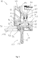
- the Fig. 1 and 2nd show a fuel connection unit 10 to be provided in a vehicle heater to be operated with fuel, which can be used, for example, as an auxiliary heater or auxiliary heater.
- the fuel connection unit 10 comprises a disk-shaped connection unit body 12, with which the fuel connection unit 10 fits into a fuel connection unit receiving opening of a heater body, to be explained below, is to be used.
- a fuel delivery line connection area, generally designated 16, is provided on the top end face 14 of the connection unit body 12. With this, the fuel connection unit 10 is to be positioned engagingly in an interior of a heater body in order to connect a fuel delivery line to the fuel connection unit in this interior.
- a fuel supply line connection area 20 is provided at the bottom end face 18 of the connection unit body 14. This is when the fuel connection unit 10 is attached to a heater body of a vehicle heater and is provided outside the vehicle heater and is provided for connecting a fuel supply line via which liquid fuel is supplied, for example, from a metering pump and a fuel tank.
- connection formation 30 is provided at the discharge opening area 28.
- a fuel delivery line for example in the form of a metal tube, can be connected to the fuel connection unit 10.
- the connection formation 30 comprises two, for example, O-ring-shaped sealing elements 32, 34, each with a sealing element insertion opening 36, 38, into which the fuel delivery line can be introduced such that the sealing elements 32, 34 are fluid-tight in their outer peripheral area on an inner peripheral surface of the delivery opening area 28 or of the delivery channel 24 and with their inner circumferential area in a fluid-tight manner on the outer circumferential surface the fuel delivery line.
- these can be separated, for example, by an annular separating disc positioned between them.
- connection formation 30 further comprises an insertion element 40, which is placed on the end region 26 of the delivery nozzle 24 and is held there, for example, by latching. With a section 42 engaging in the end region 26, the insertion element 40 holds the two sealing elements 32, 34 in the discharge opening region 28 such that they are positioned between the section 42 of the insertion element 40 and a step-like extension 44 of the discharge channel 24.
- the insertion element 40 provides a funnel-shaped fuel delivery line insertion opening 46, which on the one hand facilitates the insertion of the fuel delivery line and on the other hand ensures that it is guided or positioned in the course of the insertion movement in such a way that it is inserted into the sealing element provided by the sealing elements 32, 34 Insertion openings 36, 38 can enter without damaging the sealing elements 32, 34.
- the delivery channel 24 In a region 47 of the delivery channel 24 which adjoins the step-like expansion and which ends in a further step-like expansion area 48, the delivery channel 24 is dimensioned such that the fuel delivery line can be received therein after it has been passed through the two sealing elements 32, 34.
- the step-like extension 48 can form an insertion wedge for the fuel delivery line, so that it is ensured that it is not inserted excessively into the delivery nozzle 22 or is held therein in a defined position.
- the fuel supply line connection area 20 provided on the front side 18 comprises a supply connection 50.
- the supply connection 50 extends from the connection unit body 12 in a direction essentially opposite to the direction of extension of the delivery connection 22 and has a supply channel 52.
- the discharge nozzle 22 and the feed nozzle 50 are positioned such that they are offset essentially transversely to their respective longitudinal axes L A and Lz, but in principle extend essentially parallel to one another.
- a connection channel 54 is formed in the connection unit body 12, which, essentially extending orthogonally to the feed channel 52 or discharge channel 24, connects these two channels to one another in their end regions lying close to one another.
- the feed connector 50 has, for example, a bead-like extension 58, onto which a fuel feed line, for example a flexible hose line, can be pushed in order to fix it on the fuel feed connector 50 or to connect it to it.
- a pipe clamp or a similar fastening element can be used in order to prevent the fuel supply line from becoming detached from the supply connector 50.
- connection unit body 12 is made in one piece with the delivery nozzle 22 and the feed nozzle 50, that is to say it is designed as a block of material.
- This unit is preferably made of plastic material in a casting process.
- the connecting channel 54 is also designed as a channel which is basically open to an outer peripheral region of the connection unit body 12 and is in this The area is closed off by a closure element 60 which seals the connecting channel 54 in a fluid-tight manner.
- the closure element 60 which is also made of plastic material, for example, can be pressed into an, for example, expanded end region of the connecting channel 54 and thus held firmly therein.
- the connection channel 54 can also be sealed off in its end region which is open to the outer circumference of the connection unit body 12 by a weld closure.
- a holding formation is formed on the connection unit body 12.
- this comprises a latching tab 64, which, as described below, has a corresponding formation can cooperate on a heater body in order to hold the fuel connection unit 10 on the heater body.
- a step-like shoulder 66 is formed on the connection unit body 12, in which the connection unit body 12 is surrounded by an annular sealing element 68.
- the end region 72 for example following the external thread provided there, is surrounded by an O-ring-like sealing element 74, which on the one hand on the outer circumference of the end region 72 of the feed connector 50 and on the other hand on the inner surface of the opening 70 in the connection unit body 12 is applied and thus creates a sealing effect.
- the feed connector which is designed as a separate component, it can be screwed tightly into the opening 70 in such a way that a clamping action ensuring a stable mounting is generated.
- detachment can be prevented by gluing the feed connector 50 to the connection unit body 12.
- the feed connector 50 can be pressed with its end region 72 into the opening 70 and thus, for example also supported by the adhesive effect of an adhesive, can be held stably in the connection unit body 12.
- connection unit body 12 can be produced from plastic material in a casting process, for example with the discharge nozzle 22 formed integrally therewith, the feed nozzle 50 can be constructed from metal material, for example aluminum material.
- metal material for example aluminum material.
- the heater body 78 forms a heat exchanger arrangement 84, on the inside of which the exhaust gas discharged via an exhaust outlet connection 86 flows and on the outside of which heat transfer fins 88 provided there flow around the air to be heated.
- Fig. 5 and Fig. 7 clearly recognizable fuel connection unit receiving opening 92 is formed.
- the fuel connection unit receiving opening 92 is shaped and dimensioned such that the connection unit body 12 can be accommodated therein with a close fit and the sealing element 68 bears against an inner surface of the fuel connection unit reception opening 92 in order to produce a gas-tight connection.
- the connector unit body 12 is completely inserted into the fuel receiving opening 92, its end face 14 bears against a bottom region 94 of the fuel connector unit receiving opening 92.
- the latching tab 64 engages over a complementary formation 96 on the heater body 78, so that the fuel connection unit 10 is held in a defined position on the heater body 78 by latching engagement.
- the exhaust gas discharge pipe 86 which is preferably formed integrally with the heater body 78, is also provided and a laterally open recess 100 is also provided, into which a combustion air supply pipe 102 of the fan 84 can be positioned in an engaging manner when the fan 84 is attached to the heater body 78.
- the exhaust gas discharge pipe 86 and the combustion air supply pipe 102 define an interface with which the vehicle heater 76 is brought into connection with a complementarily shaped interface on a vehicle-fixed carrier.
- Part of this complementary interface can also be a fuel supply line , so that by attaching the fuel connection unit 10 to the heater body 78 in a defined positioning, the fuel supply line connection area 20, in particular the supply connection 50 thereof, can also assume a defined relative positioning with respect to the exhaust gas delivery connection 86 and the combustion air supply connection 102.
- the Fig. 5 shows clearly that when the fuel connection unit 10 is attached to the heater body 78, the fuel delivery line connection area 16 is positioned in the interior 80. Also extending in this interior space 80 is a fuel delivery line 104, for example in the form of a metal tube, which can be firmly connected to the combustion chamber assembly 82 and feeds liquid fuel, for example, into a porous evaporator medium in its end region located in the combustion chamber assembly 82.
- the fuel delivery line 104 which is led out of the combustion chamber assembly 82, for example, in a base region 106, is shaped and dimensioned such that it ends at a distance from an inner surface of the peripheral wall 90 of the heater body 78 when the combustion chamber assembly 82 is attached to the heater body 78.
- the combustion chamber assembly 82 with the fuel delivery line 104 provided thereon can be inserted into the heater body 78 without the fuel delivery line 104 interfering with one another with the peripheral wall 90.
- the fuel delivery line 104 is positioned such that its end area 106 to be connected to the fuel connection unit 10 is positioned in the area in which the delivery nozzle 22 with its delivery opening area 28 is positioned when the fuel connection unit 10 is inserted into the fuel connection unit receiving opening 92 .
- the fuel connection unit 10 When the fuel connection unit 10 is attached, it is inserted into the fuel connection unit receiving opening 92 in such a way that, in the course of the movement required for this purpose, the end region 106 of the fuel delivery line 104 enters the delivery opening region 28 via the funnel-shaped fuel delivery line insertion opening 46 and thereby through the sealing elements 32, 34 provided sealing element insertion openings 36, 38 is passed through.
- the end face 14 of the fuel connection unit receiving opening 92 is seated on the bottom region 94 Connection unit body 12, the end region 106 of the fuel delivery line 104 is just before or on the step-like extension 48 of the delivery channel 24.
- the delivery connection 22 and the supply connection 50 are positioned such that mutual interference between the delivery connection 22 and the fan 84 is avoided, but on the other hand the supply connection 50 offset to the delivery connection 22 is, however, in one Structure of the already mentioned interface required positioning is on the outside of the heater body 78. In this state, the fuel connection unit 10 is held on the heater body 78 by the holding formation 62.
- the fuel connection unit 10 is, in addition to the holding action provided by the holding formation 62, firmly between the bottom area 94 of the fuel connection unit receiving opening 92 and the held on the plate-like mounting area 98, vehicle-fixed carrier. Detachment of the fuel connection unit 10 is thus completely prevented.
- At least the fuel supply line connection area designed or provided for connecting a fuel supply line could be one instead of a connecting piece shown in the figures, for example in FIG Fig. 3
- Recognizable opening 70 of the connector unit body 12 include inserted quick connection unit, into which a tubular or hose-shaped fuel supply line is inserted and locked therein by clamping action.
- the sealing element 68 which provides the tight connection of the fuel connection unit 10 to the heater body 78, could be arranged surrounding the dispensing nozzle 22 and cooperate there with the peripheral wall 90 for establishing the tight connection.
Landscapes
- Engineering & Computer Science (AREA)
- Mechanical Engineering (AREA)
- General Engineering & Computer Science (AREA)
- Physics & Mathematics (AREA)
- Thermal Sciences (AREA)
- Chemical & Material Sciences (AREA)
- Combustion & Propulsion (AREA)
- Air-Conditioning For Vehicles (AREA)
Priority Applications (1)
| Application Number | Priority Date | Filing Date | Title |
|---|---|---|---|
| PL18195115T PL3467382T3 (pl) | 2017-10-05 | 2018-09-18 | Jednostka przyłącza paliwa |
Applications Claiming Priority (1)
| Application Number | Priority Date | Filing Date | Title |
|---|---|---|---|
| DE102017123046.7A DE102017123046A1 (de) | 2017-10-05 | 2017-10-05 | Kraftstoffanschlusseinheit |
Publications (2)
| Publication Number | Publication Date |
|---|---|
| EP3467382A1 EP3467382A1 (de) | 2019-04-10 |
| EP3467382B1 true EP3467382B1 (de) | 2020-08-05 |
Family
ID=63667693
Family Applications (1)
| Application Number | Title | Priority Date | Filing Date |
|---|---|---|---|
| EP18195115.3A Active EP3467382B1 (de) | 2017-10-05 | 2018-09-18 | Kraftstoffanschlusseinheit |
Country Status (7)
| Country | Link |
|---|---|
| US (1) | US11358439B2 (pl) |
| EP (1) | EP3467382B1 (pl) |
| KR (1) | KR102154973B1 (pl) |
| CN (1) | CN109624658B (pl) |
| DE (1) | DE102017123046A1 (pl) |
| PL (1) | PL3467382T3 (pl) |
| RU (1) | RU2696750C1 (pl) |
Families Citing this family (2)
| Publication number | Priority date | Publication date | Assignee | Title |
|---|---|---|---|---|
| DE102018116523B3 (de) | 2018-07-09 | 2019-09-05 | Eberspächer Climate Control Systems GmbH & Co. KG | Kraftstoffanschlusseinheit |
| DE102020101963A1 (de) * | 2020-01-28 | 2021-07-29 | Eberspächer Climate Control Systems GmbH | Fahrzeugheizgerät |
Family Cites Families (15)
| Publication number | Priority date | Publication date | Assignee | Title |
|---|---|---|---|---|
| US1799551A (en) | 1929-04-01 | 1931-04-07 | Forney Comb Engineering Compan | Oil and steam burner nozzle |
| US2290298A (en) * | 1939-12-02 | 1942-07-21 | Stewart Warner Corp | Automobile heater |
| US3849055A (en) * | 1974-03-04 | 1974-11-19 | Stacee Mfg Inc | Liquid fuel heater improvement |
| DE3136839A1 (de) * | 1981-09-16 | 1983-03-31 | Webasto-Werk W. Baier GmbH & Co, 8035 Gauting | Fahrzeugheizung |
| JP3925170B2 (ja) * | 2001-11-26 | 2007-06-06 | 東海ゴム工業株式会社 | コネクタ用遮水カバー |
| DE102004005267A1 (de) * | 2004-02-03 | 2005-08-25 | J. Eberspächer GmbH & Co. KG | Verdampferbrenner, insbesondere für ein Fahrzeugheizgerät |
| DE202004015442U1 (de) | 2004-10-05 | 2006-02-09 | J. Eberspächer GmbH & Co. KG | Steuergerät für ein Fahrzeugheizgerät zur Steuerung des Betriebs eines Luftfördergebläses |
| KR100830178B1 (ko) * | 2007-05-04 | 2008-05-16 | 주식회사 엘씨글로벌 | 엘피지 차량용 연료기화시스템 |
| KR20090042407A (ko) * | 2007-10-26 | 2009-04-30 | 한라공조주식회사 | 차량용 히터코어의 보조난방장치 및 이의 제어방법 |
| KR101094882B1 (ko) * | 2009-08-11 | 2011-12-15 | (주)모토닉 | 가스차량용 엘피아이 시스템 |
| US20110314827A1 (en) | 2010-06-24 | 2011-12-29 | General Electric Company | Fuel nozzle assembly |
| CN102393016B (zh) * | 2011-11-10 | 2013-12-04 | 山东大学 | 一种吸油衬易更换的蒸发式燃烧器 |
| DE102014217414A1 (de) * | 2014-09-01 | 2016-03-03 | Eberspächer Climate Control Systems GmbH & Co. KG | Brennkammerbaugruppe und Verfahren zum Aufbau einer Brennkammerbaugruppe |
| DE102016107207B4 (de) * | 2016-03-17 | 2020-07-09 | Eberspächer Climate Control Systems GmbH & Co. KG | Brennstoffgasbetriebenes Fahrzeugheizgerät |
| DE102017114762A1 (de) * | 2017-07-03 | 2019-01-03 | Eberspächer Climate Control Systems GmbH & Co. KG | Trägeranordnung |
-
2017
- 2017-10-05 DE DE102017123046.7A patent/DE102017123046A1/de not_active Ceased
-
2018
- 2018-09-18 EP EP18195115.3A patent/EP3467382B1/de active Active
- 2018-09-18 PL PL18195115T patent/PL3467382T3/pl unknown
- 2018-09-26 CN CN201811121727.XA patent/CN109624658B/zh active Active
- 2018-10-03 US US16/150,391 patent/US11358439B2/en active Active
- 2018-10-04 RU RU2018134972A patent/RU2696750C1/ru active
- 2018-10-05 KR KR1020180118829A patent/KR102154973B1/ko active Active
Also Published As
| Publication number | Publication date |
|---|---|
| US11358439B2 (en) | 2022-06-14 |
| DE102017123046A1 (de) | 2019-04-11 |
| EP3467382A1 (de) | 2019-04-10 |
| US20190105965A1 (en) | 2019-04-11 |
| PL3467382T3 (pl) | 2021-02-08 |
| CN109624658A (zh) | 2019-04-16 |
| RU2696750C1 (ru) | 2019-08-05 |
| CN109624658B (zh) | 2022-04-19 |
| KR102154973B1 (ko) | 2020-09-11 |
| KR20190039657A (ko) | 2019-04-15 |
Similar Documents
| Publication | Publication Date | Title |
|---|---|---|
| DE112008002469B4 (de) | Leitungsverbinder sowie Leitungssatz für fluidische Medien | |
| EP1805447B1 (de) | Zugfeste steckkupplung | |
| EP2706280B1 (de) | Steckverbinder | |
| EP3354804A1 (de) | Schlauchanschlussanordnung, verwendung einer schlauchanschlussanordnung und sanitärarmatur | |
| EP3379129A1 (de) | Anschlussverbinder | |
| EP3467382A1 (de) | Kraftstoffanschlusseinheit | |
| DE102011077955A1 (de) | Kühlbares Dosiermodul | |
| EP1677041B1 (de) | Fluidleitungsverbindungsanordnung | |
| DE19714858C1 (de) | Saugstrahlpumpe | |
| EP3414436B1 (de) | Abgasauslasssystem für ein kraftfahrzeug, kraftfahrzeug mit einem solchen abgasauslasssystem sowie verfahren zur herstellung eines abgasauslasssystems | |
| EP4058638B1 (de) | Sanitärarmatur | |
| EP2703761A1 (de) | Gasspül-Element und zugehörige Gaszuführ-Leitung | |
| DE102010010315B4 (de) | Ventilanschlussarmatur, Ventiladapterelement, Einsatzelement und Verfahren zum Einpressen eines Einsatzelements | |
| DE102017119704A1 (de) | Leitungskupplung und Behälter hiermit | |
| EP3418668B1 (de) | Wärmetauscheranordnung | |
| DE102014009327A1 (de) | Filtereinrichtung, insbesondere Flüssigkeitsfilter | |
| EP1920685A2 (de) | Fluidleitungsverbindungsanordnung | |
| DE102014225279A1 (de) | Anschlussvorrichtung für eine Fluidleitung | |
| DE102014015613A1 (de) | Hohlfilterelement und Filter mit einem Hohlfilterelement | |
| DE102013103534B4 (de) | "Steckverbindungsteil für einen Leitungsverbinder, insbesondere für eine konfektionierte Medienleitung" | |
| DE102009020942A1 (de) | Rohrverbindungssystem | |
| DE102021118799A1 (de) | Ausgleichsbehälter für einen Kühlkreislauf eines Motors eines Kraftfahrzeugs | |
| DE19912118B4 (de) | Heizgeräte-Gehäuse mit Anschlußstutzen | |
| DE102012221554B4 (de) | Filteroberschale und Verwendung in einem Ölfilter | |
| WO2005102748A1 (de) | Heiz- und belüftungseinrichtung eines kraftfahrzeugs |
Legal Events
| Date | Code | Title | Description |
|---|---|---|---|
| PUAI | Public reference made under article 153(3) epc to a published international application that has entered the european phase |
Free format text: ORIGINAL CODE: 0009012 |
|
| STAA | Information on the status of an ep patent application or granted ep patent |
Free format text: STATUS: THE APPLICATION HAS BEEN PUBLISHED |
|
| AK | Designated contracting states |
Kind code of ref document: A1 Designated state(s): AL AT BE BG CH CY CZ DE DK EE ES FI FR GB GR HR HU IE IS IT LI LT LU LV MC MK MT NL NO PL PT RO RS SE SI SK SM TR |
|
| AX | Request for extension of the european patent |
Extension state: BA ME |
|
| STAA | Information on the status of an ep patent application or granted ep patent |
Free format text: STATUS: REQUEST FOR EXAMINATION WAS MADE |
|
| 17P | Request for examination filed |
Effective date: 20191010 |
|
| RBV | Designated contracting states (corrected) |
Designated state(s): AL AT BE BG CH CY CZ DE DK EE ES FI FR GB GR HR HU IE IS IT LI LT LU LV MC MK MT NL NO PL PT RO RS SE SI SK SM TR |
|
| GRAP | Despatch of communication of intention to grant a patent |
Free format text: ORIGINAL CODE: EPIDOSNIGR1 |
|
| STAA | Information on the status of an ep patent application or granted ep patent |
Free format text: STATUS: GRANT OF PATENT IS INTENDED |
|
| INTG | Intention to grant announced |
Effective date: 20200414 |
|
| GRAS | Grant fee paid |
Free format text: ORIGINAL CODE: EPIDOSNIGR3 |
|
| GRAA | (expected) grant |
Free format text: ORIGINAL CODE: 0009210 |
|
| STAA | Information on the status of an ep patent application or granted ep patent |
Free format text: STATUS: THE PATENT HAS BEEN GRANTED |
|
| AK | Designated contracting states |
Kind code of ref document: B1 Designated state(s): AL AT BE BG CH CY CZ DE DK EE ES FI FR GB GR HR HU IE IS IT LI LT LU LV MC MK MT NL NO PL PT RO RS SE SI SK SM TR |
|
| REG | Reference to a national code |
Ref country code: GB Ref legal event code: FG4D Free format text: NOT ENGLISH |
|
| REG | Reference to a national code |
Ref country code: CH Ref legal event code: EP |
|
| REG | Reference to a national code |
Ref country code: AT Ref legal event code: REF Ref document number: 1299218 Country of ref document: AT Kind code of ref document: T Effective date: 20200815 |
|
| REG | Reference to a national code |
Ref country code: DE Ref legal event code: R082 Ref document number: 502018002102 Country of ref document: DE Representative=s name: RUTTENSPERGER LACHNIT TROSSIN GOMOLL, PATENT- , DE Ref country code: DE Ref legal event code: R081 Ref document number: 502018002102 Country of ref document: DE Owner name: EBERSPAECHER CLIMATE CONTROL SYSTEMS GMBH, DE Free format text: FORMER OWNER: EBERSPAECHER CLIMATE CONTROL SYSTEMS GMBH & CO. KG, 73730 ESSLINGEN, DE |
|
| REG | Reference to a national code |
Ref country code: DE Ref legal event code: R096 Ref document number: 502018002102 Country of ref document: DE |
|
| REG | Reference to a national code |
Ref country code: IE Ref legal event code: FG4D Free format text: LANGUAGE OF EP DOCUMENT: GERMAN |
|
| REG | Reference to a national code |
Ref country code: SE Ref legal event code: TRGR |
|
| REG | Reference to a national code |
Ref country code: FI Ref legal event code: FGE |
|
| REG | Reference to a national code |
Ref country code: LT Ref legal event code: MG4D |
|
| REG | Reference to a national code |
Ref country code: NL Ref legal event code: MP Effective date: 20200805 |
|
| REG | Reference to a national code |
Ref country code: FI Ref legal event code: PCE Owner name: EBERSPAECHER CLIMATE CONTROL SYSTEMS GMBH |
|
| PG25 | Lapsed in a contracting state [announced via postgrant information from national office to epo] |
Ref country code: LT Free format text: LAPSE BECAUSE OF FAILURE TO SUBMIT A TRANSLATION OF THE DESCRIPTION OR TO PAY THE FEE WITHIN THE PRESCRIBED TIME-LIMIT Effective date: 20200805 Ref country code: HR Free format text: LAPSE BECAUSE OF FAILURE TO SUBMIT A TRANSLATION OF THE DESCRIPTION OR TO PAY THE FEE WITHIN THE PRESCRIBED TIME-LIMIT Effective date: 20200805 Ref country code: PT Free format text: LAPSE BECAUSE OF FAILURE TO SUBMIT A TRANSLATION OF THE DESCRIPTION OR TO PAY THE FEE WITHIN THE PRESCRIBED TIME-LIMIT Effective date: 20201207 Ref country code: ES Free format text: LAPSE BECAUSE OF FAILURE TO SUBMIT A TRANSLATION OF THE DESCRIPTION OR TO PAY THE FEE WITHIN THE PRESCRIBED TIME-LIMIT Effective date: 20200805 Ref country code: BG Free format text: LAPSE BECAUSE OF FAILURE TO SUBMIT A TRANSLATION OF THE DESCRIPTION OR TO PAY THE FEE WITHIN THE PRESCRIBED TIME-LIMIT Effective date: 20201105 Ref country code: NO Free format text: LAPSE BECAUSE OF FAILURE TO SUBMIT A TRANSLATION OF THE DESCRIPTION OR TO PAY THE FEE WITHIN THE PRESCRIBED TIME-LIMIT Effective date: 20201105 Ref country code: GR Free format text: LAPSE BECAUSE OF FAILURE TO SUBMIT A TRANSLATION OF THE DESCRIPTION OR TO PAY THE FEE WITHIN THE PRESCRIBED TIME-LIMIT Effective date: 20201106 |
|
| PG25 | Lapsed in a contracting state [announced via postgrant information from national office to epo] |
Ref country code: RS Free format text: LAPSE BECAUSE OF FAILURE TO SUBMIT A TRANSLATION OF THE DESCRIPTION OR TO PAY THE FEE WITHIN THE PRESCRIBED TIME-LIMIT Effective date: 20200805 Ref country code: NL Free format text: LAPSE BECAUSE OF FAILURE TO SUBMIT A TRANSLATION OF THE DESCRIPTION OR TO PAY THE FEE WITHIN THE PRESCRIBED TIME-LIMIT Effective date: 20200805 Ref country code: LV Free format text: LAPSE BECAUSE OF FAILURE TO SUBMIT A TRANSLATION OF THE DESCRIPTION OR TO PAY THE FEE WITHIN THE PRESCRIBED TIME-LIMIT Effective date: 20200805 Ref country code: IS Free format text: LAPSE BECAUSE OF FAILURE TO SUBMIT A TRANSLATION OF THE DESCRIPTION OR TO PAY THE FEE WITHIN THE PRESCRIBED TIME-LIMIT Effective date: 20201205 |
|
| PG25 | Lapsed in a contracting state [announced via postgrant information from national office to epo] |
Ref country code: DK Free format text: LAPSE BECAUSE OF FAILURE TO SUBMIT A TRANSLATION OF THE DESCRIPTION OR TO PAY THE FEE WITHIN THE PRESCRIBED TIME-LIMIT Effective date: 20200805 Ref country code: RO Free format text: LAPSE BECAUSE OF FAILURE TO SUBMIT A TRANSLATION OF THE DESCRIPTION OR TO PAY THE FEE WITHIN THE PRESCRIBED TIME-LIMIT Effective date: 20200805 Ref country code: EE Free format text: LAPSE BECAUSE OF FAILURE TO SUBMIT A TRANSLATION OF THE DESCRIPTION OR TO PAY THE FEE WITHIN THE PRESCRIBED TIME-LIMIT Effective date: 20200805 Ref country code: SM Free format text: LAPSE BECAUSE OF FAILURE TO SUBMIT A TRANSLATION OF THE DESCRIPTION OR TO PAY THE FEE WITHIN THE PRESCRIBED TIME-LIMIT Effective date: 20200805 |
|
| REG | Reference to a national code |
Ref country code: DE Ref legal event code: R097 Ref document number: 502018002102 Country of ref document: DE |
|
| PG25 | Lapsed in a contracting state [announced via postgrant information from national office to epo] |
Ref country code: MC Free format text: LAPSE BECAUSE OF FAILURE TO SUBMIT A TRANSLATION OF THE DESCRIPTION OR TO PAY THE FEE WITHIN THE PRESCRIBED TIME-LIMIT Effective date: 20200805 Ref country code: AL Free format text: LAPSE BECAUSE OF FAILURE TO SUBMIT A TRANSLATION OF THE DESCRIPTION OR TO PAY THE FEE WITHIN THE PRESCRIBED TIME-LIMIT Effective date: 20200805 |
|
| PLBE | No opposition filed within time limit |
Free format text: ORIGINAL CODE: 0009261 |
|
| STAA | Information on the status of an ep patent application or granted ep patent |
Free format text: STATUS: NO OPPOSITION FILED WITHIN TIME LIMIT |
|
| REG | Reference to a national code |
Ref country code: BE Ref legal event code: MM Effective date: 20200930 |
|
| PG25 | Lapsed in a contracting state [announced via postgrant information from national office to epo] |
Ref country code: LU Free format text: LAPSE BECAUSE OF NON-PAYMENT OF DUE FEES Effective date: 20200918 Ref country code: SK Free format text: LAPSE BECAUSE OF FAILURE TO SUBMIT A TRANSLATION OF THE DESCRIPTION OR TO PAY THE FEE WITHIN THE PRESCRIBED TIME-LIMIT Effective date: 20200805 |
|
| 26N | No opposition filed |
Effective date: 20210507 |
|
| PG25 | Lapsed in a contracting state [announced via postgrant information from national office to epo] |
Ref country code: IT Free format text: LAPSE BECAUSE OF FAILURE TO SUBMIT A TRANSLATION OF THE DESCRIPTION OR TO PAY THE FEE WITHIN THE PRESCRIBED TIME-LIMIT Effective date: 20200805 |
|
| PG25 | Lapsed in a contracting state [announced via postgrant information from national office to epo] |
Ref country code: BE Free format text: LAPSE BECAUSE OF NON-PAYMENT OF DUE FEES Effective date: 20200930 Ref country code: SI Free format text: LAPSE BECAUSE OF FAILURE TO SUBMIT A TRANSLATION OF THE DESCRIPTION OR TO PAY THE FEE WITHIN THE PRESCRIBED TIME-LIMIT Effective date: 20200805 Ref country code: IE Free format text: LAPSE BECAUSE OF NON-PAYMENT OF DUE FEES Effective date: 20200918 |
|
| REG | Reference to a national code |
Ref country code: CH Ref legal event code: PL |
|
| PG25 | Lapsed in a contracting state [announced via postgrant information from national office to epo] |
Ref country code: TR Free format text: LAPSE BECAUSE OF FAILURE TO SUBMIT A TRANSLATION OF THE DESCRIPTION OR TO PAY THE FEE WITHIN THE PRESCRIBED TIME-LIMIT Effective date: 20200805 Ref country code: MT Free format text: LAPSE BECAUSE OF FAILURE TO SUBMIT A TRANSLATION OF THE DESCRIPTION OR TO PAY THE FEE WITHIN THE PRESCRIBED TIME-LIMIT Effective date: 20200805 Ref country code: CY Free format text: LAPSE BECAUSE OF FAILURE TO SUBMIT A TRANSLATION OF THE DESCRIPTION OR TO PAY THE FEE WITHIN THE PRESCRIBED TIME-LIMIT Effective date: 20200805 |
|
| PG25 | Lapsed in a contracting state [announced via postgrant information from national office to epo] |
Ref country code: MK Free format text: LAPSE BECAUSE OF FAILURE TO SUBMIT A TRANSLATION OF THE DESCRIPTION OR TO PAY THE FEE WITHIN THE PRESCRIBED TIME-LIMIT Effective date: 20200805 |
|
| PG25 | Lapsed in a contracting state [announced via postgrant information from national office to epo] |
Ref country code: LI Free format text: LAPSE BECAUSE OF NON-PAYMENT OF DUE FEES Effective date: 20210930 Ref country code: CH Free format text: LAPSE BECAUSE OF NON-PAYMENT OF DUE FEES Effective date: 20210930 |
|
| GBPC | Gb: european patent ceased through non-payment of renewal fee |
Effective date: 20220918 |
|
| PG25 | Lapsed in a contracting state [announced via postgrant information from national office to epo] |
Ref country code: GB Free format text: LAPSE BECAUSE OF NON-PAYMENT OF DUE FEES Effective date: 20220918 |
|
| REG | Reference to a national code |
Ref country code: AT Ref legal event code: MM01 Ref document number: 1299218 Country of ref document: AT Kind code of ref document: T Effective date: 20230918 |
|
| PG25 | Lapsed in a contracting state [announced via postgrant information from national office to epo] |
Ref country code: AT Free format text: LAPSE BECAUSE OF NON-PAYMENT OF DUE FEES Effective date: 20230918 |
|
| PG25 | Lapsed in a contracting state [announced via postgrant information from national office to epo] |
Ref country code: AT Free format text: LAPSE BECAUSE OF NON-PAYMENT OF DUE FEES Effective date: 20230918 |
|
| PGFP | Annual fee paid to national office [announced via postgrant information from national office to epo] |
Ref country code: FI Payment date: 20250922 Year of fee payment: 8 |
|
| PGFP | Annual fee paid to national office [announced via postgrant information from national office to epo] |
Ref country code: DE Payment date: 20250930 Year of fee payment: 8 |
|
| PGFP | Annual fee paid to national office [announced via postgrant information from national office to epo] |
Ref country code: PL Payment date: 20250905 Year of fee payment: 8 |
|
| PGFP | Annual fee paid to national office [announced via postgrant information from national office to epo] |
Ref country code: FR Payment date: 20250922 Year of fee payment: 8 |
|
| PGFP | Annual fee paid to national office [announced via postgrant information from national office to epo] |
Ref country code: SE Payment date: 20250922 Year of fee payment: 8 |
|
| PGFP | Annual fee paid to national office [announced via postgrant information from national office to epo] |
Ref country code: CZ Payment date: 20250905 Year of fee payment: 8 |
|
| PGFP | Annual fee paid to national office [announced via postgrant information from national office to epo] |
Ref country code: AT Payment date: 20260410 Year of fee payment: 5 |