EP3466650B1 - Vorrichtung zur additiven herstellung dreidimensionaler objekte - Google Patents
Vorrichtung zur additiven herstellung dreidimensionaler objekte Download PDFInfo
- Publication number
- EP3466650B1 EP3466650B1 EP18203050.2A EP18203050A EP3466650B1 EP 3466650 B1 EP3466650 B1 EP 3466650B1 EP 18203050 A EP18203050 A EP 18203050A EP 3466650 B1 EP3466650 B1 EP 3466650B1
- Authority
- EP
- European Patent Office
- Prior art keywords
- exposure device
- process chamber
- laser beam
- exposure
- frame structure
- Prior art date
- Legal status (The legal status is an assumption and is not a legal conclusion. Google has not performed a legal analysis and makes no representation as to the accuracy of the status listed.)
- Active
Links
- 239000000654 additive Substances 0.000 title claims description 10
- 230000000996 additive effect Effects 0.000 title claims description 10
- 238000004519 manufacturing process Methods 0.000 title claims description 8
- 238000000034 method Methods 0.000 claims description 90
- 238000010276 construction Methods 0.000 claims description 73
- 239000004566 building material Substances 0.000 claims description 23
- 239000000463 material Substances 0.000 claims description 9
- 230000008878 coupling Effects 0.000 claims description 8
- 238000010168 coupling process Methods 0.000 claims description 8
- 238000005859 coupling reaction Methods 0.000 claims description 8
- 238000007711 solidification Methods 0.000 claims description 8
- 230000008023 solidification Effects 0.000 claims description 8
- 239000002184 metal Substances 0.000 claims description 5
- 229910052751 metal Inorganic materials 0.000 claims description 5
- 239000011248 coating agent Substances 0.000 description 11
- 238000000576 coating method Methods 0.000 description 11
- 229910000831 Steel Inorganic materials 0.000 description 3
- 238000007596 consolidation process Methods 0.000 description 3
- 238000010309 melting process Methods 0.000 description 3
- 239000010959 steel Substances 0.000 description 3
- 229910001374 Invar Inorganic materials 0.000 description 2
- 229910001030 Iron–nickel alloy Inorganic materials 0.000 description 2
- 238000005253 cladding Methods 0.000 description 2
- 239000011521 glass Substances 0.000 description 2
- 230000003287 optical effect Effects 0.000 description 2
- 238000000110 selective laser sintering Methods 0.000 description 2
- 230000015572 biosynthetic process Effects 0.000 description 1
- 229910010293 ceramic material Inorganic materials 0.000 description 1
- 230000001419 dependent effect Effects 0.000 description 1
- 238000010586 diagram Methods 0.000 description 1
- 230000000694 effects Effects 0.000 description 1
- 238000010438 heat treatment Methods 0.000 description 1
- 239000000843 powder Substances 0.000 description 1
- 230000005855 radiation Effects 0.000 description 1
Images

Classifications
-
- B—PERFORMING OPERATIONS; TRANSPORTING
- B22—CASTING; POWDER METALLURGY
- B22F—WORKING METALLIC POWDER; MANUFACTURE OF ARTICLES FROM METALLIC POWDER; MAKING METALLIC POWDER; APPARATUS OR DEVICES SPECIALLY ADAPTED FOR METALLIC POWDER
- B22F10/00—Additive manufacturing of workpieces or articles from metallic powder
-
- B—PERFORMING OPERATIONS; TRANSPORTING
- B29—WORKING OF PLASTICS; WORKING OF SUBSTANCES IN A PLASTIC STATE IN GENERAL
- B29C—SHAPING OR JOINING OF PLASTICS; SHAPING OF MATERIAL IN A PLASTIC STATE, NOT OTHERWISE PROVIDED FOR; AFTER-TREATMENT OF THE SHAPED PRODUCTS, e.g. REPAIRING
- B29C64/00—Additive manufacturing, i.e. manufacturing of three-dimensional [3D] objects by additive deposition, additive agglomeration or additive layering, e.g. by 3D printing, stereolithography or selective laser sintering
- B29C64/20—Apparatus for additive manufacturing; Details thereof or accessories therefor
- B29C64/264—Arrangements for irradiation
-
- B—PERFORMING OPERATIONS; TRANSPORTING
- B22—CASTING; POWDER METALLURGY
- B22F—WORKING METALLIC POWDER; MANUFACTURE OF ARTICLES FROM METALLIC POWDER; MAKING METALLIC POWDER; APPARATUS OR DEVICES SPECIALLY ADAPTED FOR METALLIC POWDER
- B22F12/00—Apparatus or devices specially adapted for additive manufacturing; Auxiliary means for additive manufacturing; Combinations of additive manufacturing apparatus or devices with other processing apparatus or devices
- B22F12/38—Housings, e.g. machine housings
-
- B—PERFORMING OPERATIONS; TRANSPORTING
- B22—CASTING; POWDER METALLURGY
- B22F—WORKING METALLIC POWDER; MANUFACTURE OF ARTICLES FROM METALLIC POWDER; MAKING METALLIC POWDER; APPARATUS OR DEVICES SPECIALLY ADAPTED FOR METALLIC POWDER
- B22F3/00—Manufacture of workpieces or articles from metallic powder characterised by the manner of compacting or sintering; Apparatus specially adapted therefor ; Presses and furnaces
- B22F3/003—Apparatus, e.g. furnaces
-
- B—PERFORMING OPERATIONS; TRANSPORTING
- B29—WORKING OF PLASTICS; WORKING OF SUBSTANCES IN A PLASTIC STATE IN GENERAL
- B29C—SHAPING OR JOINING OF PLASTICS; SHAPING OF MATERIAL IN A PLASTIC STATE, NOT OTHERWISE PROVIDED FOR; AFTER-TREATMENT OF THE SHAPED PRODUCTS, e.g. REPAIRING
- B29C64/00—Additive manufacturing, i.e. manufacturing of three-dimensional [3D] objects by additive deposition, additive agglomeration or additive layering, e.g. by 3D printing, stereolithography or selective laser sintering
- B29C64/20—Apparatus for additive manufacturing; Details thereof or accessories therefor
- B29C64/25—Housings, e.g. machine housings
-
- B—PERFORMING OPERATIONS; TRANSPORTING
- B33—ADDITIVE MANUFACTURING TECHNOLOGY
- B33Y—ADDITIVE MANUFACTURING, i.e. MANUFACTURING OF THREE-DIMENSIONAL [3-D] OBJECTS BY ADDITIVE DEPOSITION, ADDITIVE AGGLOMERATION OR ADDITIVE LAYERING, e.g. BY 3-D PRINTING, STEREOLITHOGRAPHY OR SELECTIVE LASER SINTERING
- B33Y10/00—Processes of additive manufacturing
-
- B—PERFORMING OPERATIONS; TRANSPORTING
- B33—ADDITIVE MANUFACTURING TECHNOLOGY
- B33Y—ADDITIVE MANUFACTURING, i.e. MANUFACTURING OF THREE-DIMENSIONAL [3-D] OBJECTS BY ADDITIVE DEPOSITION, ADDITIVE AGGLOMERATION OR ADDITIVE LAYERING, e.g. BY 3-D PRINTING, STEREOLITHOGRAPHY OR SELECTIVE LASER SINTERING
- B33Y30/00—Apparatus for additive manufacturing; Details thereof or accessories therefor
-
- B—PERFORMING OPERATIONS; TRANSPORTING
- B22—CASTING; POWDER METALLURGY
- B22F—WORKING METALLIC POWDER; MANUFACTURE OF ARTICLES FROM METALLIC POWDER; MAKING METALLIC POWDER; APPARATUS OR DEVICES SPECIALLY ADAPTED FOR METALLIC POWDER
- B22F10/00—Additive manufacturing of workpieces or articles from metallic powder
- B22F10/20—Direct sintering or melting
- B22F10/28—Powder bed fusion, e.g. selective laser melting [SLM] or electron beam melting [EBM]
-
- B—PERFORMING OPERATIONS; TRANSPORTING
- B22—CASTING; POWDER METALLURGY
- B22F—WORKING METALLIC POWDER; MANUFACTURE OF ARTICLES FROM METALLIC POWDER; MAKING METALLIC POWDER; APPARATUS OR DEVICES SPECIALLY ADAPTED FOR METALLIC POWDER
- B22F12/00—Apparatus or devices specially adapted for additive manufacturing; Auxiliary means for additive manufacturing; Combinations of additive manufacturing apparatus or devices with other processing apparatus or devices
- B22F12/40—Radiation means
- B22F12/49—Scanners
-
- Y—GENERAL TAGGING OF NEW TECHNOLOGICAL DEVELOPMENTS; GENERAL TAGGING OF CROSS-SECTIONAL TECHNOLOGIES SPANNING OVER SEVERAL SECTIONS OF THE IPC; TECHNICAL SUBJECTS COVERED BY FORMER USPC CROSS-REFERENCE ART COLLECTIONS [XRACs] AND DIGESTS
- Y02—TECHNOLOGIES OR APPLICATIONS FOR MITIGATION OR ADAPTATION AGAINST CLIMATE CHANGE
- Y02P—CLIMATE CHANGE MITIGATION TECHNOLOGIES IN THE PRODUCTION OR PROCESSING OF GOODS
- Y02P10/00—Technologies related to metal processing
- Y02P10/25—Process efficiency
Definitions
- Device for the additive production of three-dimensional objects by successive layer-by-layer selective exposure and the associated successive layer-by-layer selective solidification of building material layers made of a building material solidifiable by means of a laser beam comprising a process chamber and an exposure device with the further features of the preamble of claim 1.
- Corresponding devices for additive manufacturing of three-dimensional objects are, for. B. in the form of devices for performing selective laser sintering or selective laser melting processes, known per se.
- Corresponding devices include a process chamber in which the successive layer-by-layer selective exposure and the associated successive layer-by-layer selective consolidation of the respective building material layers takes place, as well as an exposure device which is set up to generate a laser beam for selective exposure and the associated consolidation of the respective building material layers.
- EP-A-1600282 discloses the features of the preamble of claim 1.
- the process heat generated during the operation of corresponding devices causes the process chamber to be heated.
- the invention is based on the object of specifying a device for the additive manufacture of three-dimensional objects which is improved in comparison.
- the object is achieved by a device for the additive manufacture of three-dimensional objects according to claim 1.
- the dependent ones Claims relate to possible embodiments of the device.
- the apparatus (“apparatus”) described herein is for the additive manufacturing of three-dimensional objects, i. H.
- the building material can in particular be a particulate or powdery metal, plastic and / or ceramic material.
- the selective consolidation of the respective building material layers to be selectively strengthened takes place on the basis of object-related construction data.
- Corresponding construction data describe the geometrical-constructive shape of the object to be produced additively in each case and can, for example, contain "sliced" CAD data of the object to be produced additively.
- the device can be used as an SLM device; H. as a device for carrying out selective laser melting processes (SLM process), or as an SLS device, d. H. be designed as a device for carrying out selective laser sintering processes (SLS processes).
- the device comprises the functional components typically required to carry out additive construction processes. These include in particular a coating device and an exposure device.
- the coating device is set up to form layers of building material to be selectively solidified (in the building level of the device).
- the coating device can comprise several components, i. H. z. B. a coating element, in particular a blade-shaped coating tool, and a guide device for guiding the coating element along a defined movement path.
- the exposure device is set up to generate a laser beam for selective exposure and the associated solidification of the respective building material layers (in the building plane of the device).
- the exposure device can also comprise several components, ie, for example, a beam generating device for generating a laser beam, a beam deflecting device (scanner device) for deflecting a laser beam generated by the beam generating device onto a selectively to be exposed area of a selectively solidified building material layer and various optical elements, such as B. filter elements, objective elements, lens elements, etc.
- the exposure device can also be referred to or regarded as the optics of the device.
- the exposure device is arranged or formed on a housing construction formed by one or more, in particular profile-like or profile-shaped, frame construction elements or comprising such a housing construction, heat-decoupled from the process chamber.
- a heat-decoupled spaced-apart arrangement or design of the exposure device, d. H. in particular a beam deflection device belonging to the exposure device, relative to the process chamber it is to be understood that no heat (thermal energy), which could possibly lead to an undesired change in the positioning, i.e. H. the alignment and / or arrangement that could lead exposure device can be transferred from the process chamber to the exposure device.
- the exposure device is spatially spaced from the process chamber in such a way that no heat transfer from the process chamber to the exposure device is possible.
- the exposure device is completely decoupled from the process chamber from a thermal point of view; a heat transfer from the process chamber to the exposure device (and vice versa) is not possible.
- a gap defining a distance between the exposure device and the process chamber is typically formed between the exposure device and the process chamber.
- the gap can define a distance between the exposure device and the process chamber of a few millimeters, ie in particular a distance of at least one millimeter. Accordingly, there is typically no physical, ie in particular no mechanical, contact between the exposure device and the process chamber which could enable heat to be transferred from the process chamber to the exposure device.
- the exposure device is arranged on a frame structure.
- the frame construction can be an outer housing frame construction of the device, which typically forms a (closed) housing or cladding construction of the device and accordingly defines (essentially) the outer shape of the device.
- the frame construction on which the exposure device is arranged or formed is not the outer housing frame construction of the device.
- the device can e.g. B. comprise a (common) frame construction on which the exposure device and the process chamber are arranged or formed.
- the exposure device is arranged or designed at such a distance from the process chamber on the frame construction that a change in the positioning of the exposure device on the frame construction does not take place or is not possible due to the thermal energy introduced into the frame construction via the process chamber during operation of the device.
- the thermal energy introduced into the frame construction via the process chamber during operation of the device is simply not sufficient, in particular due to thermal expansion, to cause an undesired change in the positioning of the exposure device.
- the device can comprise a plurality of separate frame constructions which are arranged at a distance from one another in a heat-decoupled manner, the exposure device being arranged or formed on a first frame construction and the process chamber on a second frame construction.
- a heat-decoupled arrangement of the respective frame constructions that are spaced apart from one another is to be understood that no heat (thermal energy), which could possibly lead to an undesired change in the positioning, ie. H. the orientation and / or arrangement, the exposure device could lead, can be transferred from the second frame structure to the first frame structure.
- the respective frame structures are spatially spaced from one another in such a way that no heat transfer from the second frame structure to the first frame structure is possible.
- the respective frame constructions can be arranged one inside the other, the second frame construction structurally and structurally having smaller dimensions than the first frame construction.
- the second frame construction can be regarded or referred to as the inner frame construction, the first frame construction as the outer frame construction. This enables a compact, at the same time heat-decoupled arrangement constitutes respective frame constructions.
- the interior space defined by the first or the outer frame construction can optionally be rendered inert.
- the exposure device can be mounted on a separate frame construction section or on a separate frame construction element which is formed from a material, in particular a metal, with a coefficient of thermal expansion in a range between 0.5 and 3.0 ⁇ x 10 -6 K -1 , be arranged or formed.
- a material in particular a metal
- the coefficient of thermal expansion in a temperature range between 20 and 90 ° C
- the frame construction on which the exposure device is arranged or formed is expediently formed from a material with a comparatively low coefficient of thermal expansion (coefficient of linear or spatial expansion).
- a gap defining a distance between the exposure device and the process chamber is typically formed between the exposure device and the process chamber.
- at least one can be located between the exposure device, in particular a laser beam decoupling point of the exposure device or a beam deflection device associated therewith, via which a laser beam is decoupled or exits from the exposure device, in particular a beam deflection device associated with the exposure device, and a laser beam coupling point, in particular a laser beam coupling window, via which a laser beam couples or enters a process chamber interior defined by the process chamber, arranged or formed shielding element for shielding the laser beam extending between the exposure device, in particular the laser beam exit point of the exposure device, and the process chamber, in particular the laser beam coupling point of the process chamber, arranged or formed .
- the shielding element can have a bellows-like or -shaped or a sleeve-like or -shaped geometrical-structural shape and is formed from a suitable shielding material, ie, for example, glass, steel, etc.
- the shielding element ensures a shielding of the device, ie it prevents an undesired exit of the laser beam, in particular via the gap extending between the exposure device and the process chamber, from the device.
- a shielding housing construction comprising at least one, in particular flat, shielding element, which is arranged or constructed around the frame construction on which the exposure device is arranged or constructed.
- the shielding housing construction represents an enclosure of at least the frame construction on which the exposure device is arranged or formed, which prevents an undesired exit of the laser beam, in particular via the gap extending between the exposure device and the process chamber, from the device.
- the device 1 is used for the additive production of three-dimensional objects 2, i. H. in particular technical components or technical component groups, by successive layer-by-layer selective exposure and the associated successive layer-by-layer selective solidification of building material layers made of a solidifiable building material 3, d. H. z. B. a metal powder, by means of laser radiation, see laser beam 4.
- the selective solidification of the respective building material layers to be solidified takes place on the basis of object-related building data.
- Corresponding construction data describe the geometric or geometric-constructive shape of the object 2 to be produced additively in each case and can contain, for example, “sliced” CAD data of the object 2 to be produced.
- the device 1 can be used as a Laser-CUSING® device, i. H. be designed as a device for carrying out selective laser melting processes.
- the device 1 comprises the functional components required to carry out additive construction processes; in the figures is only one Coating device 5 and an exposure device 6 are shown.
- the coating device 5 is set up for the formation of building material layers to be selectively exposed or selectively solidified in a building plane of the device 1.
- the coating device 5 comprises a coating element assembly (not designated in more detail) comprising a plurality of coating elements, which is mounted movably in the horizontal direction in a process chamber 7 of the device 1 via a guide device (not shown), as indicated by the double arrow P1.
- the exposure device 6 is set up for the selective exposure of building material layers to be selectively solidified in the building plane of the device 1 and for this purpose comprises a beam generating device (not shown) which is set up to generate a laser beam 4, a beam deflection device (not shown) which is used to deflect one of the Beam generating device generated laser beam 4 is set up on an area to be exposed of a selectively solidified building material layer, as well as various optical elements, such as. B. filter elements, objective elements, lens elements, etc.
- the exposure device 6 can also be referred to as the optics of the device 1.
- the figures also show a metering module 8, a construction module 9 and an overflow module 10, which are docked to a lower region of the process chamber 7 of the device 1.
- the modules mentioned can also form a lower region of the process chamber 7.
- the exposure device 6 is at one by one or more, z. B. profile-like or -shaped, frame construction elements (unspecified) formed or such a comprehensive housing construction 11 is heat-decoupled and spaced from the process chamber 7.
- a heat-decoupled arrangement or design of the exposure device 6, ie in particular the beam deflection device associated with the exposure device 6, relative to the process chamber 7 is to be understood as meaning that no heat (thermal energy), which may lead to an undesired change in the positioning, ie the alignment and / or arrangement which could lead exposure device 6 (for example relative to a reference positioning) from process chamber 7 to Exposure device 6 can be transferred.
- the exposure device 6 is spatially spaced from the process chamber 7 in such a way that no heat transfer from the process chamber 7 to the exposure device 6 is possible. The exposure device 6 is therefore completely decoupled from the process chamber 7 from a thermal point of view.
- a gap 12 defining a distance between the exposure device 6 and the process chamber 7 is formed between the exposure device 6 and the process chamber 7.
- the gap 12 can be a distance of a few millimeters, i. H. in particular define a distance of at least one millimeter. Accordingly, between the exposure device 6 and the process chamber 7 there is no physical, i.e. H. in particular no mechanical contact which could allow heat to be transferred from the process chamber 7 to the exposure device 6.
- the exposure device 6 is arranged on a frame structure 11, which forms an outer housing frame structure of the device 1.
- the housing frame construction forms the (closed) housing or cladding construction of the device 1 and accordingly defines (essentially) the external shape of the device 1.
- the process chamber 7 is also arranged on the frame structure 11.
- the device 1 accordingly comprises a (common) frame construction 11 on which the exposure device 6 and the process chamber 7 are arranged.
- the exposure device 6 is arranged at such a distance from the process chamber 7 on the frame structure 11 that the positioning of the exposure device 6 on the frame structure 11 does not change due to the thermal energy introduced into the frame structure 11 via the process chamber 7 during operation of the device 1 . not possible.
- the exposure device 6 is spaced apart from the process chamber 7 in this way arranged that the thermal energy introduced into the frame structure 11 via the process chamber 7 during operation of the device 1 is insufficient, in particular due to thermal expansion, to cause an undesired change in the positioning of the exposure device 6.
- the exposure device 6 is arranged on a separate frame construction section (first frame construction section 11a) or on a separate frame construction element of the frame construction 11, which is made of a material, in particular a metal, with a coefficient of thermal expansion in one Range between 0.5 and 3.0 x 10 -6 K -1 is formed.
- a corresponding material it can be, for. B. to be an iron-nickel alloy known under the name "Invar”, the coefficient of thermal expansion (in a temperature range between 20 and 90 ° C) between 0.5 and 2.0 x 10 -6 K -1 .
- the embodiment shown shows the possibility that in the gap 12 a between the exposure device 6, in particular a laser beam decoupling point (not designated in detail) of the exposure device 6 or the associated beam deflection device, via which the laser beam 4 from the exposure device 6, in particular that of the exposure device 6 associated beam deflection device, decouples or exits and a laser beam coupling point (unspecified), in particular a laser beam coupling window 14, through which the laser beam 4 couples or enters into the process chamber interior 15 defined by the process chamber 7, arranged or formed shielding element 16 for shielding the laser beam 4 extending between the exposure device 6, in particular the laser beam exit point of the exposure device 6, and the process chamber 7, in particular the laser beam coupling point of the process chamber 7, is arranged.
- the shielding element 16 has a bellows-like or a sleeve-like geometrical-structural shape and is formed from a suitable shielding material, ie, for example, glass, steel, etc..
- the shielding element 16 ensures a shielding of the device 1, ie it prevents an undesired exit of the laser beam 4, in particular via the gap 12 extending between the exposure device and the process chamber, from the device 1.
- the device 1 comprises several separate frame structures 11, 13, which are arranged at a distance from one another in a heat-decoupled manner.
- the exposure device 6 is arranged on a first frame structure 11 and the process chamber 7 is arranged on a second frame structure 13.
- a heat-decoupled arrangement of the respective frame structures 11, 13 that are spaced apart from each other is also to be understood as meaning that no heat (thermal energy), which could possibly lead to an undesired change in the positioning of the exposure device 6, is transferred from the second frame structure 13 to the first frame structure 11 can.
- the respective frame structures 11, 13 are spatially spaced from one another in such a way that no heat transfer from the second frame structure 13 to the first frame structure 11 is possible.
- the two frame structures 11, 13 are in the in Fig. 2 shown embodiment arranged one inside the other.
- the second frame construction 13 has structurally and structurally smaller dimensions than the first frame construction 11.
- the second frame construction 13 can in this respect be regarded or referred to as an inner frame construction and the first frame construction 11 as an outer frame construction.
- the interior space defined by the first or outer frame structure 11 can optionally be rendered inert.
- the embodiment shown is to ensure a shielding of the device 1, ie an undesired exit of the laser beam 4, in particular via the one between the exposure device 6 and the process chamber 7 extending gap space 12, to prevent from the device 1, an at least one, in particular flat, made of a suitable shielding material, for. B. a steel, formed, shielding element (unspecified) comprehensive shielding housing structure 17, which is arranged around the frame structure 11 on which the exposure device 6 is arranged.
- the shielding housing construction 17 represents a housing of the frame construction 11, on which the exposure device 6 is arranged, which prevents an undesired exit of the laser beam 4, in particular via the gap 12 extending between the exposure device 6 and the process chamber 7, from the device 1.
Description
- Vorrichtung zur additiven Herstellung dreidimensionaler Objekte durch sukzessive schichtweise selektive Belichtung und damit einhergehende sukzessive schichtweise selektive Verfestigung von Baumaterialschichten aus einem vermittels eines Laserstrahls verfestigbaren Baumaterial, umfassend eine Prozesskammer und eine Belichtungseinrichtung mit den weiteren Merkmalen des Oberbegriffs des Anspruchs 1.
- Entsprechende Vorrichtungen zur additiven Herstellung dreidimensionaler Objekte sind, z. B. in Form von Vorrichtungen zur Durchführung selektiver Lasersinter- bzw. selektiver Laserschmelzverfahren, an und für sich bekannt. Entsprechende Vorrichtungen umfassen eine Prozesskammer, in welcher die sukzessive schichtweise selektive Belichtung und die damit einhergehende sukzessive schichtweise selektive Verfestigung jeweiliger Baumaterialschichten erfolgt, sowie eine Belichtungseinrichtung, welcher zur Erzeugung eines Laserstrahls zur selektiven Belichtung und damit einhergehenden Verfestigung jeweiliger Baumaterialschichten eingerichtet ist.
-
EP-A-1600282 offenbart die Merkmale des Oberbegriffs des Anspruchs 1. - Die im Betrieb entsprechender Vorrichtungen prozessbedingt entstehende Prozesswärme bedingt eine Erwärmung der Prozesskammer. Bis dato ist es üblich, die Belichtungseinrichtung unmittelbar an bzw. auf einer freiliegenden Außenfläche der Prozesskammer anzuordnen, sodass die Erwärmung und die damit einhergehende thermische Ausdehnung der Prozesskammer unweigerlich zu einer gewissen Änderung der Positionierung der exakt zu positionierenden bzw. exakt positionierten Belichtungseinrichtung führen kann.
- Dies stellt einen verbesserungswürdigen Zustand dar, als sich Änderungen der Positionierung der Belichtungseinrichtung negativ auf eine exakte Belichtung jeweiliger selektiv zu belichtender bzw. zu verfestigender Baumaterialschichten und somit auf die Qualität der herzustellenden Objekte auswirken können.
- Der Erfindung liegt die Aufgabe zugrunde, eine demgegenüber verbesserte Vorrichtung zur additiven Herstellung dreidimensionaler Objekte anzugeben.
- Die Aufgabe wird durch eine Vorrichtung zur additiven Herstellung dreidimensionaler Objekte gemäß Anspruch 1 gelöst. Die hierzu abhängigen Ansprüche betreffen mögliche Ausführungsformen der Vorrichtung.
- Die hierin beschriebene Vorrichtung ("Vorrichtung") ist zur additiven Herstellung dreidimensionaler Objekte, d. h. beispielsweise technischer Bauteile bzw. technischer Bauteilgruppen, durch sukzessive schichtweise selektive Belichtung und damit einhergehende sukzessive schichtweise selektive Verfestigung von Baumaterialschichten aus einem vermittels eines Laserstrahls verfestigbaren Baumaterial eingerichtet. Bei dem Baumaterial kann es sich insbesondere um ein partikuläres bzw. pulverförmiges Metall-, Kunststoff- und/oder Keramikmaterial handeln. Die selektive Verfestigung jeweiliger selektiv zu verfestigender Baumaterialschichten erfolgt auf Grundlage objektbezogener Baudaten. Entsprechende Baudaten beschreiben die geometrisch-konstruktive Gestalt des jeweils additiv herzustellenden Objekts und können beispielsweise "geslicte" CAD-Daten des additiv herzustellenden Objekts beinhalten. Die Vorrichtung kann als SLM-Vorrichtung, d. h. als Vorrichtung zur Durchführung selektiver Laserschmelzverfahren (SLM-Verfahren), oder als SLS-Vorrichtung, d. h. als Vorrichtung zur Durchführung selektiver Lasersinterverfahren (SLS-Verfahren), ausgebildet sein.
- Die Vorrichtung umfasst die zur Durchführung additiver Bauvorgänge typischerweise erforderlichen Funktionskomponenten. Hierzu zählen insbesondere eine Beschichtungseinrichtung und eine Belichtungseinrichtung. Die Beschichtungseinrichtung ist zur Ausbildung selektiv zu verfestigender Baumaterialschichten (in der Bauebene der Vorrichtung) eingerichtet. Die Beschichtungseinrichtung kann mehrere Bestandteile umfassen, d. h. z. B. ein ein, insbesondere klingenförmiges, Beschichtungswerkzeug umfassendes Beschichtungselement sowie eine Führungseinrichtung zur Führung des Beschichtungselements entlang einer definierten Bewegungsbahn.
- Die Belichtungseinrichtung ist zur Erzeugung eines Laserstrahls zur selektiven Belichtung und damit einhergehenden Verfestigung jeweiliger Baumaterialschichten (in der Bauebene der Vorrichtung) eingerichtet. Auch die Belichtungseinrichtung kann mehrere Bestandteile umfassen, d. h. z. B. eine Strahlerzeugungseinrichtung zur Erzeugung eines Laserstrahls, eine Strahlablenkeinrichtung (Scannereinrichtung) zur Ablenkung eines von der Strahlerzeugungseinrichtung erzeugten Laserstrahls auf einen selektiv zu belichtenden Bereich einer selektiv zu verfestigenden Baumaterialschicht sowie diverse optische Elemente, wie z. B. Filterelemente, Objektivelemente, Linsenelemente, etc. Die Belichtungseinrichtung kann auch als Optik der Vorrichtung bezeichnet bzw. erachtet werden.
- Die Belichtungseinrichtung ist an einer durch ein oder mehrere, insbesondere profilartige bzw. -förmige, Gestellkonstruktionselemente gebildete oder solche umfassende Gehäusekonstruktion wärmeentkoppelt beabstandet von der Prozesskammer angeordnet oder ausgebildet. Unter einer wärmeentkoppelt beabstandeten Anordnung oder Ausbildung der Belichtungseinrichtung, d. h. insbesondere einer der Belichtungseinrichtung zugehörigen Strahlablenkeinrichtung, relativ zu der Prozesskammer ist zu verstehen, dass keine Wärme (thermische Energie), welche gegebenenfalls zu einer unerwünschten Änderung der Positionierung, d. h. der Ausrichtung und/oder Anordnung, der Belichtungseinrichtung führen könnte, von der Prozesskammer auf die Belichtungseinrichtung übertragen werden kann. Die Belichtungseinrichtung ist derart räumlich von der Prozesskammer beabstandet, dass keine Wärmeübertragung von der Prozesskammer auf die Belichtungseinrichtung möglich ist. Die Belichtungseinrichtung ist in thermischer Hinsicht völlig von der Prozesskammer entkoppelt; ein Wärmeübergang von der Prozesskammer auf die Belichtungseinrichtung (und umgekehrt) ist nicht möglich.
- Zwischen der Belichtungseinrichtung und der Prozesskammer ist demnach typischerweise ein einen Abstand zwischen der Belichtungseinrichtung und der Prozesskammer definierender Spaltraum gebildet. Der Spaltraum kann einen Abstand zwischen der Belichtungseinrichtung und der Prozesskammer von einigen Millimetern, d. h. insbesondere einen Abstand von wenigstens einem Millimeter, definieren. Zwischen der Belichtungseinrichtung und der Prozesskammer besteht demnach typischerweise kein physikalischer, d. h. insbesondere kein mechanischer, Kontakt, welcher eine Wärmeübertragung von der Prozesskammer auf die Belichtungseinrichtung ermöglichen könnte.
- Derart ist der im Zusammenhang mit dem eingangs beschriebenen Stand der Technik beschriebenen Problematik begegnet, als es durch die wärmeentkoppelt beabstandet von der Prozesskammer angeordnete oder ausgebildete Belichtungseinrichtung nicht möglich ist, dass die sich im Betrieb entsprechender Vorrichtungen aufgrund der prozessbedingt entstehenden Prozesswärme erwärmende Prozesskammer einen negativen Einfluss auf die Positionierung der Belichtungseinrichtung hat.
- Die Belichtungseinrichtung ist an einer Gestellkonstruktion angeordnet. Bei der Gestellkonstruktion kann es sich um eine äußere Gehäusegestellkonstruktion der Vorrichtung handeln, welche typischerweise eine (geschlossene) Gehäuse- bzw. Verkleidungskonstruktion der Vorrichtung bildet und sonach im (im Wesentlichen) die äußere Gestalt der Vorrichtung definiert. Wie sich im Weiteren ergibt, bestehen andere Ausführungsformen, gemäß welchen es sich bei der Gestellkonstruktion, an welcher die Belichtungseinrichtung angeordnet oder ausgebildet ist, nicht um die äußere Gehäusegestellkonstruktion der Vorrichtung handelt.
- Im Hinblick auf die Anordnung bzw. Ausbildung der Belichtungseinrichtung an der Gestellkonstruktion bestehen unterschiedliche Möglichkeiten, welche im Weiteren näher erläutert werden.
- Die Vorrichtung kann z. B. eine (gemeinsame) Gestellkonstruktion umfassen, an welcher die Belichtungseinrichtung und die Prozesskammer angeordnet oder ausgebildet sind. Die Belichtungseinrichtung ist dabei derart beabstandet von der Prozesskammer an der Gestellkonstruktion angeordnet oder ausgebildet, dass eine Änderung der Positionierung der Belichtungseinrichtung an der Gestellkonstruktion aufgrund der im Betrieb der Vorrichtung über die Prozesskammer in die Gestellkonstruktion eingebrachten thermischen Energie nicht erfolgt bzw. nicht möglich ist. Die im Betrieb der Vorrichtung über die Prozesskammer in die Gestellkonstruktion eingebrachte thermische Energie reicht schlicht nicht aus, insbesondere aufgrund thermischer Ausdehnung, eine unerwünschte Änderung der Positionierung der Belichtungseinrichtung zu bedingen.
- Dies kann konstruktiv z. B. derart realisiert sein, dass die Belichtungseinrichtung an wenigstens einem ersten Gestellkonstruktionsabschnitt und die Prozesskammer an wenigstens einem weiteren Gestellkonstruktionsabschnitt angeordnet oder ausgebildet ist, wobei der wenigstens eine erste Gestellkonstruktionsabschnitt derart beabstandet von dem wenigstens einen weiteren Gestellkonstruktionsabschnitt angeordnet oder ausgebildet ist, dass eine Änderung der Positionierung der Belichtungseinrichtung an der Gestellkonstruktion aufgrund der im Betrieb der Vorrichtung über die Prozesskammer in die Gestellkonstruktion eingebrachten thermischen Energie nicht erfolgt bzw. nicht möglich ist.
- Alternativ kann die Vorrichtung mehrere gesonderte wärmeentkoppelt voneinander beabstandet angeordnete Gestellkonstruktionen umfassen, wobei die Belichtungseinrichtung an einer ersten Gestellkonstruktion und die Prozesskammer an einer zweiten Gestellkonstruktion angeordnet oder ausgebildet ist. Auch in diesem Zusammenhang ist unter einer wärmeentkoppelt voneinander beabstandeten Anordnung jeweiliger Gestellkonstruktionen zu verstehen, dass keine Wärme (thermische Energie), welche gegebenenfalls zu einer unerwünschten Änderung der Positionierung, d. h. der Ausrichtung und/oder Anordnung, der Belichtungseinrichtung führen könnte, von der zweiten Gestellkonstruktion auf die erste Gestellkonstruktion übertragen werden kann. Die jeweiligen Gestellkonstruktionen sind derart räumlich voneinander beabstandet, dass keine Wärmeübertragung von der zweiten Gestellkonstruktion auf die erste Gestellkonstruktion möglich ist.
- Die jeweiligen Gestellkonstruktionen können ineinander angeordnet sein, wobei die zweite Gestellkonstruktion baulich-konstruktiv geringere Abmessungen aufweist als die erste Gestellkonstruktion. Die zweite Gestellkonstruktion kann insofern als innere Gestellkonstruktion, die erste Gestellkonstruktion als äußere Gestellkonstruktion erachtet bzw. bezeichnet werden. Dies ermöglicht einen kompakte, gleichwohl wärmeentkoppelte Anordnung jeweilige Gestellkonstruktionen dar. Der durch die erste bzw. die äußere Gestellkonstruktion definierte Innenraum kann gegebenenfalls inertisierbar sein.
- Die Belichtungseinrichtung kann an einem gesonderten Gestellkonstruktionsabschnitt bzw. an einem gesonderten Gestellkonstruktionselement, welcher bzw. welches aus einem Material, insbesondere einem Metall, mit einem Wärmeausdehnungskoeffizienten in einem Bereich zwischen 0,5 und 3,0·x 10-6K-1 gebildet ist, angeordnet oder ausgebildet sein. Bei einem entsprechenden Material kann es sich z. B. um eine unter der Bezeichnung "Invar" bekannte Eisen-Nickel-Legierung handeln, deren Wärmeausdehnungskoeffizient (in einem Temperaturbereich zwischen 20 und 90°C) zwischen 0,5 und 2,0 × 10⁻⁶K-1 liegt. An dieser Stelle ist allgemein anzumerken, dass die Gestellkonstruktion, an welcher die Belichtungseinrichtung angeordnet oder ausgebildet ist, zweckmäßig aus einem Material mit einem vergleichsweise geringen Wärmeausdehnungskoeffizient (Längen- bzw. Raumausdehnungskoeffizient) gebildet ist.
- Wie erwähnt, ist zwischen der Belichtungseinrichtung und der Prozesskammer typischerweise ein einen Abstand zwischen der Belichtungseinrichtung und der Prozesskammer definierender Spaltraum gebildet. In dem Spaltraum kann wenigstens ein sich zwischen der Belichtungseinrichtung, insbesondere einem Laserstrahlauskopplungspunkt der Belichtungseinrichtung bzw. einer dieser zugehörigen Strahlablenkeinrichtung, über welchen ein Laserstrahl aus der Belichtungseinrichtung, insbesondere einer der Belichtungseinrichtung zugehörigen Strahlablenkeinrichtung, auskoppelt bzw. austritt und einem Laserstrahleinkopplungspunkt, insbesondere einem Laserstrahleinkopplungsfenster, über welchen ein Laserstrahl in einen durch die Prozesskammer definierten Prozesskammerinnenraum einkoppelt bzw. eintritt, angeordnetes oder ausgebildetes Abschirmelement zur Abschirmung des sich zwischen der Belichtungseinrichtung, insbesondere dem Laserstrahlaustrittspunkt der Belichtungseinrichtung, und der Prozesskammer, insbesondere dem Laserstrahleinkopplungspunkt der Prozesskammer, erstreckenden Laserstrahls angeordnet oder ausgebildet sein. Das Abschirmelement kann eine faltenbalgartige bzw. -förmige oder eine hülsenartige bzw. -förmige geometrisch-konstruktive Gestalt aufweisen und ist aus einem geeigneten Abschirmmaterial, d. h. z. B. Glas, Stahl, etc. gebildet. Das Abschirmelement stellt eine Abschirmung der Vorrichtung sicher, d. h. es verhindert einen unerwünschten Austritt des Laserstrahls, insbesondere über den sich zwischen der Belichtungseinrichtung und der Prozesskammer erstreckenden Spaltraum, aus der Vorrichtung.
- Mit dem gleichen Zweck ist es auch denkbar, dass eine wenigstens ein, insbesondere flächiges, Abschirmelement umfassende Abschirmgehäusekonstruktion, welche um die Gestellkonstruktion, an welcher die Belichtungseinrichtung angeordnet oder ausgebildet ist, angeordnet oder ausgebildet ist. Die Abschirmgehäusekonstruktion stellt eine Einhausung wenigstens der Gestellkonstruktion, an welcher die Belichtungseinrichtung angeordnet oder ausgebildet ist, dar, welche einen unerwünschten Austritt des Laserstrahls, insbesondere über den sich zwischen der Belichtungseinrichtung und der Prozesskammer erstreckenden Spaltraum, aus der Vorrichtung verhindert.
- Die Erfindung ist anhand von Ausführungsbeispielen in den Zeichnungsfiguren näher erläutert. Dabei zeigen:
-
Fig. 1 - 3 je eine Prinzipdarstellung einer Vorrichtung gemäß einem Ausführungsbeispiel. - Die
Fig. 1 ― 3 zeigen jeweils eine Prinzipdarstellung einer Vorrichtung 1 gemäß einem Ausführungsbeispiel der Vorrichtung 1. - Die Vorrichtung 1 dient der additiven Herstellung dreidimensionaler Objekte 2, d. h. insbesondere technischer Bauteile bzw. technischer Bauteilgruppen, durch sukzessives schichtweises selektives Belichten und damit einhergehendes sukzessives schichtweises selektives Verfestigen von Baumaterialschichten aus einem verfestigbaren Baumaterial 3, d. h. z. B. eines Metallpulvers, vermittels Laserstrahlung, vgl. Laserstrahl 4. Die selektive Verfestigung jeweiliger zu verfestigender Baumaterialschichten erfolgt auf Grundlage von objektbezogenen Baudaten. Entsprechende Baudaten beschreiben die geometrische bzw. geometrisch-konstruktive Gestalt des jeweils additiv herzustellenden Objekts 2 und können beispielsweise "geslicete" CAD-Daten des herzustellenden Objekts 2 beinhalten. Die Vorrichtung 1 kann als Laser-CUSING®-Vorrichtung, d. h. als Vorrichtung zur Durchführung selektiver Laserschmelzverfahren, ausgebildet sein.
- Die Vorrichtung 1 umfasst die zur Durchführung additiver Bauvorgänge erforderlichen Funktionskomponenten; in den Fig. ist lediglich eine Beschichtungseinrichtung 5 und eine Belichtungseinrichtung 6 gezeigt.
- Die Beschichtungseinrichtung 5 ist zur Ausbildung selektiv zu belichtender bzw. selektiv zu verfestigender Baumaterialschichten in einer Bauebene der Vorrichtung 1 eingerichtet. Die Beschichtungseinrichtung 5 umfasst eine mehrere Beschichterelemente umfassende Beschichterelementbaugruppe (nicht näher bezeichnet), welche über eine Führungseinrichtung (nicht gezeigt) in, wie durch den Doppelpfeil P1 angedeutet, horizontaler Richtung in einer Prozesskammer 7 der Vorrichtung 1 bewegbar gelagert ist.
- Die Belichtungseinrichtung 6 ist zur selektiven Belichtung selektiv zu verfestigender Baumaterialschichten in der Bauebene der Vorrichtung 1 eingerichtet und umfasst hierfür eine Strahlerzeugungseinrichtung (nicht gezeigt), welche zur Erzeugung eines Laserstrahls 4 eingerichtet ist, eine Strahlablenkeinrichtung (nicht gezeigt), welche zur Ablenkung eines von der Strahlerzeugungseinrichtung erzeugten Laserstrahls 4 auf einen zu belichtenden Bereich einer selektiv zu verfestigenden Baumaterialschicht eingerichtet ist, sowie diverse optische Elemente, wie z. B. Filterelemente, Objektivelemente, Linsenelemente, etc. Die Belichtungseinrichtung 6 kann auch als Optik der Vorrichtung 1 bezeichnet bzw. erachtet werden.
- In den Fig. ist ferner ein Dosiermodul 8, ein Baumodul 9 und ein Überlaufmodul 10 dargestellt, welche an einen unteren Bereich der Prozesskammer 7 der Vorrichtung 1 angedockt sind. Die genannten Module können auch einen unteren Bereich der Prozesskammer 7 bilden.
- Die Belichtungseinrichtung 6 ist an einer durch ein oder mehrere, z. B. profilartige bzw. -förmige, Gestellkonstruktionselemente (nicht näher bezeichnet) gebildete bzw. solche umfassende Gehäusekonstruktion 11 wärmeentkoppelt beabstandet von der Prozesskammer 7 angeordnet. Unter einer wärmeentkoppelt beabstandeten Anordnung oder Ausbildung der Belichtungseinrichtung 6, d. h. insbesondere der der Belichtungseinrichtung 6 zugehörigen Strahlablenkeinrichtung, relativ zu der Prozesskammer 7 ist zu verstehen, dass keine Wärme (thermische Energie), welche gegebenenfalls zu einer unerwünschten Änderung der Positionierung, d. h. der Ausrichtung und/oder Anordnung, der Belichtungseinrichtung 6 (z. B. relativ zu einer Referenzpositionierung) führen könnte, von der Prozesskammer 7 auf die Belichtungseinrichtung 6 übertragen werden kann. Die Belichtungseinrichtung 6 ist derart räumlich von der Prozesskammer 7 beabstandet, dass keine Wärmeübertragung von der Prozesskammer 7 auf die Belichtungseinrichtung 6 möglich ist. Die Belichtungseinrichtung 6 ist in thermischer Hinsicht also völlig von der Prozesskammer 7 entkoppelt.
- Ersichtlich ist zwischen der Belichtungseinrichtung 6 und der Prozesskammer 7 ein einen Abstand zwischen der Belichtungseinrichtung 6 und der Prozesskammer 7 definierender Spaltraum 12 gebildet. Der Spaltraum 12 kann einen Abstand von einigen Millimetern, d. h. insbesondere einen Abstand von wenigstens einem Millimeter, definieren. Zwischen der Belichtungseinrichtung 6 und der Prozesskammer 7 besteht demnach kein physikalischer, d. h. insbesondere kein mechanischer, Kontakt, welcher eine Wärmeübertragung von der Prozesskammer 7 auf die Belichtungseinrichtung 6 ermöglichen könnte.
- Mit anderen Worten ist es durch die wärmeentkoppelt beabstandete Anordnung der Belichtungseinrichtung 6 von der Prozesskammer 7 nicht möglich ist, dass die sich im Betrieb der Vorrichtung 1 aufgrund der prozessbedingt entstehenden Prozesswärme erwärmende Prozesskammer 7 einen negativen Einfluss auf die Positionierung der Belichtungseinrichtung 6 hat.
- In dem in
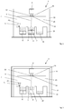
Fig. 1 gezeigten Ausführungsbeispiel ist die Belichtungseinrichtung 6 an einer Gestellkonstruktion 11, welche eine äußere Gehäusegestellkonstruktion der Vorrichtung 1 bildet, angeordnet. Die Gehäusegestellkonstruktion bildet die (geschlossene) Gehäuse- bzw. Verkleidungskonstruktion der Vorrichtung 1 und definiert sonach im (im Wesentlichen) die äußere Gestalt der Vorrichtung 1. - In dem in
Fig. 1 gezeigten Ausführungsbeispiel ist auch die Prozesskammer 7 an der Gestellkonstruktion 11 angeordnet. Die Vorrichtung 1 umfasst sonach eine (gemeinsame) Gestellkonstruktion 11, an welcher die Belichtungseinrichtung 6 und die Prozesskammer 7 angeordnet sind. Die Belichtungseinrichtung 6 ist dabei derart beabstandet von der Prozesskammer 7 an der Gestellkonstruktion 11 angeordnet, dass eine Änderung der Positionierung der Belichtungseinrichtung 6 an der Gestellkonstruktion 11 aufgrund der im Betrieb der Vorrichtung 1 über die Prozesskammer 7 in die Gestellkonstruktion 11 eingebrachten thermischen Energie nicht erfolgt bzw. nicht möglich ist. Die Belichtungseinrichtung 6 ist derart von der Prozesskammer 7 beabstandet angeordnet, dass die im Betrieb der Vorrichtung 1 über die Prozesskammer 7 in die Gestellkonstruktion 11 eingebrachte thermische Energie nicht ausreicht, insbesondere aufgrund thermischer Ausdehnung, eine unerwünschte Änderung der Positionierung der Belichtungseinrichtung 6 zu bedingen. - Dies ist konstruktiv derart realisiert, dass die Belichtungseinrichtung 6 an einem ersten Gestellkonstruktionsabschnitt 11a und die Prozesskammer 7 an einem weiteren Gestellkonstruktionsabschnitt 11b angeordnet ist, wobei der erste Gestellkonstruktionsabschnitt 11a derart beabstandet von dem weiteren Gestellkonstruktionsabschnitt 11b angeordnet ist, dass eine Änderung der Positionierung der Belichtungseinrichtung 6 an der Gestellkonstruktion 11 aufgrund der im Betrieb der Vorrichtung 1 über die Prozesskammer 7 in die Gestellkonstruktion 11 eingebrachten thermischen Energie nicht erfolgt bzw. nicht möglich ist.
- In dem in
Fig. 1 gezeigten Ausführungsbeispiel ist weiter die Möglichkeit dargestellt, dass die Belichtungseinrichtung 6 an einem gesonderten Gestellkonstruktionsabschnitt (erster Gestellkonstruktionsabschnitt 11a) bzw. an einem gesonderten Gestellkonstruktionselement der Gestellkonstruktion 11 angeordnet ist, welcher bzw. welches aus einem Material, insbesondere einem Metall, mit einem Wärmeausdehnungskoeffizienten in einem Bereich zwischen 0,5 und 3,0·x 10-6K-1 gebildet ist. Bei einem entsprechenden Material kann es sich z. B. um eine unter der Bezeichnung "Invar" bekannte Eisen-Nickel-Legierung handeln, deren Wärmeausdehnungskoeffizient (in einem Temperaturbereich zwischen 20 und 90°C) zwischen 0,5 und 2,0 x 10⁻⁶K-1 liegt. - Schließlich ist in dem in
Fig. 1 gezeigten Ausführungsbeispiel die Möglichkeit dargestellt, dass in dem Spaltraum 12 ein sich zwischen der Belichtungseinrichtung 6, insbesondere einem Laserstrahlauskopplungspunkt (nicht näher bezeichnet) der Belichtungseinrichtung 6 bzw. der dieser zugehörigen Strahlablenkeinrichtung, über welchen der Laserstrahl 4 aus der Belichtungseinrichtung 6, insbesondere der der Belichtungseinrichtung 6 zugehörigen Strahlablenkeinrichtung, auskoppelt bzw. austritt und einem Laserstrahleinkopplungspunkt (nicht näher bezeichnet), insbesondere einem Laserstrahleinkopplungsfenster 14, über welchen der Laserstrahl 4 in den durch die Prozesskammer 7 definierten Prozesskammerinnenraum 15 einkoppelt bzw. eintritt, angeordnetes oder ausgebildetes Abschirmelement 16 zur Abschirmung des sich zwischen der Belichtungseinrichtung 6, insbesondere dem Laserstrahlaustrittspunkt der Belichtungseinrichtung 6, und der Prozesskammer 7, insbesondere dem Laserstrahleinkopplungspunkt der Prozesskammer 7, erstreckenden Laserstrahls 4 angeordnet ist. Das Abschirmelement 16 weist eine faltenbalgartige oder eine hülsenartige geometrisch-konstruktive Gestalt auf und ist aus einem geeigneten Abschirmmaterial, d. h. z. B. Glas, Stahl, etc. gebildet. Das Abschirmelement 16 stellt eine Abschirmung der Vorrichtung 1 sicher, d. h. es verhindert einen unerwünschten Austritt des Laserstrahls 4, insbesondere über den sich zwischen der Belichtungseinrichtung und der Prozesskammer erstreckenden Spaltraum 12, aus der Vorrichtung 1. - In dem in
Fig. 2 gezeigten Ausführungsbeispiel umfasst die Vorrichtung 1 mehrere gesonderte wärmeentkoppelt voneinander beabstandet angeordnete Gestellkonstruktionen 11, 13. Die Belichtungseinrichtung 6 an einer ersten Gestellkonstruktion 11 und die Prozesskammer 7 an einer zweiten Gestellkonstruktion 13 angeordnet. Auch unter einer wärmeentkoppelt voneinander beabstandeten Anordnung jeweiliger Gestellkonstruktionen 11, 13 ist zu verstehen, dass keine Wärme (thermische Energie), welche gegebenenfalls zu einer unerwünschten Änderung der Positionierung der Belichtungseinrichtung 6 führen könnte, von der zweiten Gestellkonstruktion 13 auf die erste Gestellkonstruktion 11 übertragen werden kann. Die jeweiligen Gestellkonstruktionen 11, 13 sind derart räumlich voneinander beabstandet, dass keine Wärmeübertragung von der zweiten Gestellkonstruktion 13 auf die erste Gestellkonstruktion 11 möglich ist. - Die beiden Gestellkonstruktionen 11, 13 sind in dem in
Fig. 2 gezeigten Ausführungsbeispiel ineinander angeordnet. Die zweite Gestellkonstruktion 13 weist baulich-konstruktiv geringere Abmessungen auf als die erste Gestellkonstruktion 11. Die zweite Gestellkonstruktion 13 kann insofern als innere Gestellkonstruktion, die erste Gestellkonstruktion 11 als äußere Gestellkonstruktion erachtet bzw. bezeichnet werden. Der durch die erste bzw. äußere Gestellkonstruktion 11 definierte Innenraum kann gegebenenfalls inertisierbar sein. - In dem in
Fig. 3 gezeigten Ausführungsbeispiel ist, um eine Abschirmung der Vorrichtung 1 sicherzustellen, d. h. einen unerwünschten Austritt des Laserstrahls 4, insbesondere über den sich zwischen der Belichtungseinrichtung 6 und der Prozesskammer 7 erstreckenden Spaltraum 12, aus der Vorrichtung 1 zu verhindern, eine wenigstens ein, insbesondere flächiges, aus einem geeigneten Abschirmmaterial, z. B. einem Stahl, gebildetes, Abschirmelement (nicht näher bezeichnet) umfassende Abschirmgehäusekonstruktion 17, welche um die Gestellkonstruktion 11, an welcher die Belichtungseinrichtung 6 angeordnet ist, angeordnet ist. Die Abschirmgehäusekonstruktion 17 stellt eine Einhausung der Gestellkonstruktion 11, an welcher die Belichtungseinrichtung 6 angeordnet ist, dar, welche einen unerwünschten Austritt des Laserstrahls 4, insbesondere über den sich zwischen der Belichtungseinrichtung 6 und der Prozesskammer 7 erstreckenden Spaltraum 12, aus der Vorrichtung 1 verhindert.
Claims (6)
- Vorrichtung (1) zur additiven Herstellung dreidimensionaler Objekte (2) durch sukzessive schichtweise selektive Belichtung und damit einhergehende sukzessive schichtweise selektive Verfestigung von Baumaterialschichten aus einem vermittels eines Laserstrahls (4) verfestigbaren Baumaterial (3), umfassendeine Prozesskammer (7), in welcher die sukzessive schichtweise selektive Belichtung und die damit einhergehende sukzessive schichtweise selektive Verfestigung jeweiliger Baumaterialschichten aus einem vermittels eines Laserstrahls (4) verfestigbaren Baumaterial (3) erfolgt, undeine Belichtungseinrichtung (6), welche zur Erzeugung eines Laserstrahls (4) zur selektiven Belichtung und damit einhergehenden Verfestigung jeweiliger Baumaterialschichten eingerichtet ist, wobeidie Belichtungseinrichtung (6) an einer Gehäusekonstruktion (11) wärmeentkoppelt beabstandet von der Prozesskammer (7) angeordnet oder ausgebildet ist, dadurch gekennzeichnet, dass zwischen der Belichtungseinrichtung (6) und der Prozesskammer (7) ein einen Abstand zwischen der Belichtungseinrichtung (6) und der Prozesskammer (7) definierender Spaltraum (12) gebildet ist, weiter umfassendwenigstens ein sich zwischen der Belichtungseinrichtung (6), insbesondere einem Laserstrahlauskopplungspunkt der Belichtungseinrichtung (6), über welchen ein Laserstrahl (4) aus der Belichtungseinrichtung (6), insbesondere einer der Belichtungseinrichtung (6) zugehörigen Strahlablenkeinrichtung, auskoppelt und einem Laserstrahleinkopplungspunkt, über welchen ein Laserstrahl (4) in einen durch die Prozesskammer (7) definierten Prozesskammerinnenraum (15) einkoppelt, und der Prozesskammer (7) angeordnetes oder ausgebildetes, insbesondere faltenbalgartiges oder hülsenartiges, Abschirmelement (16) zur Abschirmung des sich zwischen der Belichtungseinrichtung (6), insbesondere dem Laserstrahlaustrittspunkt der Belichtungseinrichtung (6), und der Prozesskammer (7), insbesondere dem Laserstrahleinkopplungspunkt der Prozesskammer (7), erstreckenden Laserstrahls (4).
- Vorrichtung nach Anspruch 1, dadurch gekennzeichnet, dass die Vorrichtung (1) eine Gestellkonstruktion (11) umfasst, an welcher die Belichtungseinrichtung (6) und die Prozesskammer (7) angeordnet oder ausgebildet sind, wobei die Belichtungseinrichtung (6) derart beabstandet von der Prozesskammer (7) an der Gestellkonstruktion (11) angeordnet oder ausgebildet ist, dass eine Änderung der Positionierung der Belichtungseinrichtung (6) an der Gestellkonstruktion (11) aufgrund der im Betrieb der Vorrichtung (1) über die Prozesskammer (7) in die Gestellkonstruktion (11) eingebrachten thermischen Energie nicht erfolgt.
- Vorrichtung nach Anspruch 2, dadurch gekennzeichnet, dass die Belichtungseinrichtung (6) an wenigstens einem ersten Gestellkonstruktionsabschnitt (11a) und die Prozesskammer (7) an wenigstens einem weiteren Gestellkonstruktionsabschnitt (11b) angeordnet oder ausgebildet ist, wobei der wenigstens eine erste Gestellkonstruktionsabschnitt (11a) derart beabstandet von dem wenigstens einen weiteren Gestellkonstruktionsabschnitt (11b) angeordnet oder ausgebildet ist, dass eine Änderung der Positionierung der Belichtungseinrichtung (6) an der Gestellkonstruktion (11) aufgrund der im Betrieb der Vorrichtung (1) über die Prozesskammer (7) in die Gestellkonstruktion (11) eingebrachten thermischen Energie nicht erfolgt.
- Vorrichtung nach Anspruch 1, dadurch gekennzeichnet, dass die Vorrichtung mehrere gesonderte wärmeentkoppelt voneinander beabstandet angeordnete Gestellkonstruktionen (11, 13) umfasst, wobei die Belichtungseinrichtung (6) an einer ersten Gestellkonstruktion (11) und die Prozesskammer (7) an einer zweiten Gestellkonstruktion (13) angeordnet oder ausgebildet ist.
- Vorrichtung nach einem der vorhergehenden Ansprüche, dadurch gekennzeichnet, dass die Belichtungseinrichtung (6) an einem gesonderten Gestellkonstruktionsabschnitt (11a), welcher aus einem Material, insbesondere einem Metall, mit einem Wärmeausdehnungskoeffizienten in einem Bereich zwischen 0,5 und 3,0 x·10-6K-1 gebildet ist, angeordnet oder ausgebildet ist.
- Vorrichtung nach einem der vorhergehenden Ansprüche, gekennzeichnet durch eine wenigstens ein Abschirmelement umfassende Abschirmgehäusekonstruktion (17), welche um die Gestellkonstruktion (11), an welcher die Belichtungseinrichtung (6) angeordnet oder ausgebildet ist, angeordnet oder ausgebildet ist.
Applications Claiming Priority (2)
| Application Number | Priority Date | Filing Date | Title |
|---|---|---|---|
| DE102016121951.7A DE102016121951A1 (de) | 2016-11-15 | 2016-11-15 | Vorrichtung zur additiven Herstellung dreidimensionaler Objekte |
| EP17178085.1A EP3321068B1 (de) | 2016-11-15 | 2017-06-27 | Vorrichtung zur additiven herstellung dreidimensionaler objekte |
Related Parent Applications (2)
| Application Number | Title | Priority Date | Filing Date |
|---|---|---|---|
| EP17178085.1A Division EP3321068B1 (de) | 2016-11-15 | 2017-06-27 | Vorrichtung zur additiven herstellung dreidimensionaler objekte |
| EP17178085.1A Division-Into EP3321068B1 (de) | 2016-11-15 | 2017-06-27 | Vorrichtung zur additiven herstellung dreidimensionaler objekte |
Publications (2)
| Publication Number | Publication Date |
|---|---|
| EP3466650A1 EP3466650A1 (de) | 2019-04-10 |
| EP3466650B1 true EP3466650B1 (de) | 2021-11-10 |
Family
ID=59227610
Family Applications (2)
| Application Number | Title | Priority Date | Filing Date |
|---|---|---|---|
| EP18203050.2A Active EP3466650B1 (de) | 2016-11-15 | 2017-06-27 | Vorrichtung zur additiven herstellung dreidimensionaler objekte |
| EP17178085.1A Active EP3321068B1 (de) | 2016-11-15 | 2017-06-27 | Vorrichtung zur additiven herstellung dreidimensionaler objekte |
Family Applications After (1)
| Application Number | Title | Priority Date | Filing Date |
|---|---|---|---|
| EP17178085.1A Active EP3321068B1 (de) | 2016-11-15 | 2017-06-27 | Vorrichtung zur additiven herstellung dreidimensionaler objekte |
Country Status (5)
| Country | Link |
|---|---|
| US (1) | US20180133799A1 (de) |
| EP (2) | EP3466650B1 (de) |
| JP (2) | JP2018080388A (de) |
| CN (1) | CN108067617B (de) |
| DE (1) | DE102016121951A1 (de) |
Families Citing this family (5)
| Publication number | Priority date | Publication date | Assignee | Title |
|---|---|---|---|---|
| JP7048741B2 (ja) * | 2017-11-20 | 2022-04-05 | エスエルエム ソルーションズ グループ アーゲー | 三次元加工品を製造するための器械及び方法 |
| EP3575089A1 (de) * | 2018-05-30 | 2019-12-04 | CL Schutzrechtsverwaltungs GmbH | Stützstruktur zum stützen einer funktionalen komponente einer vorrichtung zur generativen fertigung eines dreidimensionalen objekts |
| JP2023527986A (ja) * | 2020-05-27 | 2023-07-03 | シューラット テクノロジーズ,インク. | 積層製造用印刷カートリッジ |
| DE102022112241A1 (de) * | 2022-05-16 | 2023-11-16 | Dmg Mori Additive Gmbh | Additive Fertigungsvorrichtung mit entkoppelter Prozesskammer und additives Fertigungsverfahren |
| WO2024003264A1 (en) * | 2022-07-01 | 2024-01-04 | Freemelt Ab | Additive manufacturing using a particle beam |
Citations (8)
| Publication number | Priority date | Publication date | Assignee | Title |
|---|---|---|---|---|
| US6767499B1 (en) | 1998-02-19 | 2004-07-27 | Ecole Nationale Superieure De Ceramique Industrielle (Ensci) | Fast prototyping method by laser sintering of powder |
| DE10342882A1 (de) | 2003-09-15 | 2005-05-19 | Trumpf Werkzeugmaschinen Gmbh + Co. Kg | Vorrichtung und Verfahren zur Herstellung eines dreidimensionalen Formkörpers |
| EP1347853B1 (de) | 2000-11-27 | 2005-10-26 | National University Of Singapore | Verfahren und vorrichtung zur herstellung eines dreidimensionalen metallteils unter verwendung von hochtemperatur-direktlaserschmelzen |
| DE102004057865B4 (de) | 2004-11-30 | 2008-01-10 | Cl Schutzrechtsverwaltungs Gmbh | Vorrichtung zum Herstellen eines dreidimensionalen Objektes |
| JP4857377B2 (ja) | 2009-12-18 | 2012-01-18 | 株式会社アマダ | 3次元造形物製造装置 |
| EP2431113B1 (de) | 2009-05-15 | 2014-07-02 | Panasonic Corporation | Vorrichtung für geschichtete modellierung und verfahren mit dieser vorrichtung zur herstellung dreidimensionaler objekte |
| US20150352668A1 (en) | 2008-09-05 | 2015-12-10 | Mtt Technologies Limited | Additive manufacturing apparatus with a chamber and a removably-mountable optical module; method of preparing a laser processing apparatus with such removably-mountable optical module |
| WO2017085470A1 (en) | 2015-11-16 | 2017-05-26 | Renishaw Plc | Module for additive manufacturing apparatus and method |
Family Cites Families (16)
| Publication number | Priority date | Publication date | Assignee | Title |
|---|---|---|---|---|
| JPS5410495A (en) * | 1977-06-23 | 1979-01-26 | Mitsubishi Electric Corp | Laser working apparatus with reflector |
| US5252264A (en) * | 1991-11-08 | 1993-10-12 | Dtm Corporation | Apparatus and method for producing parts with multi-directional powder delivery |
| DE9400346U1 (de) * | 1994-01-11 | 1994-03-10 | Eos Electro Optical Syst | Vorrichtung zum Herstellen eines dreidimensionalen Objekts |
| JP2001053361A (ja) * | 1999-08-11 | 2001-02-23 | Ishikawajima Harima Heavy Ind Co Ltd | レーザ装置用光学定盤 |
| DE10053741C1 (de) * | 2000-10-30 | 2002-02-21 | Concept Laser Gmbh | Vorrichtung zum Sintern, Abtragen und/oder Beschriften mittels elektromagnetischer gebündelter Strahlung |
| AU2002250075B2 (en) * | 2001-02-14 | 2007-03-29 | H. C. Starck, Inc. | Rejuvenation of refractory metal products |
| US20050263934A1 (en) * | 2004-05-28 | 2005-12-01 | 3D Systems, Inc. | Single side feed parked powder wave heating with wave flattener |
| DE102004057866B4 (de) | 2004-11-30 | 2010-06-10 | Cl Schutzrechtsverwaltungs Gmbh | Vorrichtung zum Herstellen von dreidimensionalen Objekten |
| US7585450B2 (en) * | 2005-09-30 | 2009-09-08 | 3D Systems, Inc. | Rapid prototyping and manufacturing system and method |
| DE202009013899U1 (de) * | 2009-10-13 | 2010-02-18 | Trumpf Werkzeugmaschinen Gmbh + Co. Kg | Abschirmungsvorrichtung an einem Bearbeitungskopf sowie Bearbeitungskopf und Bearbeitungsmaschine mit einer Abschirmungsvorrichtung |
| DE102010015657A1 (de) * | 2010-04-20 | 2011-10-20 | Valeo Schalter Und Sensoren Gmbh | Sensorbaugruppe zur Erfassung der Temperatur im Innenraum eines Fahrzeugs und Vorrichtung zur Ermittlung der Temperatur im Innenraum eines Fahrzeugs |
| DE102012212587A1 (de) * | 2012-07-18 | 2014-01-23 | Eos Gmbh Electro Optical Systems | Vorrichtung und Verfahren zum schichtweisen Herstellen eines dreidimensionalen Objekts |
| US9063305B2 (en) * | 2012-11-26 | 2015-06-23 | Avago Technologies General Ip (Singapore) Pte. Ltd. | Methods and systems for dissipating heat in optical communications modules |
| JP2014125643A (ja) * | 2012-12-25 | 2014-07-07 | Honda Motor Co Ltd | 三次元造形装置および三次元造形方法 |
| DE102013109162A1 (de) * | 2013-08-23 | 2015-02-26 | Fit Fruth Innovative Technologien Gmbh | Vorrichtung zum Herstellen dreidimensionaler Objekte |
| DE102015200134A1 (de) * | 2015-01-08 | 2016-07-14 | Trumpf Laser- Und Systemtechnik Gmbh | Modular aufgebaute SLM- oder SLS-Bearbeitungsmaschine |
-
2016
- 2016-11-15 DE DE102016121951.7A patent/DE102016121951A1/de not_active Withdrawn
-
2017
- 2017-06-27 EP EP18203050.2A patent/EP3466650B1/de active Active
- 2017-06-27 EP EP17178085.1A patent/EP3321068B1/de active Active
- 2017-08-28 CN CN201710748570.2A patent/CN108067617B/zh not_active Expired - Fee Related
- 2017-11-08 JP JP2017215278A patent/JP2018080388A/ja active Pending
- 2017-11-15 US US15/813,560 patent/US20180133799A1/en not_active Abandoned
-
2020
- 2020-07-31 JP JP2020130494A patent/JP2020180379A/ja not_active Ceased
Patent Citations (8)
| Publication number | Priority date | Publication date | Assignee | Title |
|---|---|---|---|---|
| US6767499B1 (en) | 1998-02-19 | 2004-07-27 | Ecole Nationale Superieure De Ceramique Industrielle (Ensci) | Fast prototyping method by laser sintering of powder |
| EP1347853B1 (de) | 2000-11-27 | 2005-10-26 | National University Of Singapore | Verfahren und vorrichtung zur herstellung eines dreidimensionalen metallteils unter verwendung von hochtemperatur-direktlaserschmelzen |
| DE10342882A1 (de) | 2003-09-15 | 2005-05-19 | Trumpf Werkzeugmaschinen Gmbh + Co. Kg | Vorrichtung und Verfahren zur Herstellung eines dreidimensionalen Formkörpers |
| DE102004057865B4 (de) | 2004-11-30 | 2008-01-10 | Cl Schutzrechtsverwaltungs Gmbh | Vorrichtung zum Herstellen eines dreidimensionalen Objektes |
| US20150352668A1 (en) | 2008-09-05 | 2015-12-10 | Mtt Technologies Limited | Additive manufacturing apparatus with a chamber and a removably-mountable optical module; method of preparing a laser processing apparatus with such removably-mountable optical module |
| EP2431113B1 (de) | 2009-05-15 | 2014-07-02 | Panasonic Corporation | Vorrichtung für geschichtete modellierung und verfahren mit dieser vorrichtung zur herstellung dreidimensionaler objekte |
| JP4857377B2 (ja) | 2009-12-18 | 2012-01-18 | 株式会社アマダ | 3次元造形物製造装置 |
| WO2017085470A1 (en) | 2015-11-16 | 2017-05-26 | Renishaw Plc | Module for additive manufacturing apparatus and method |
Also Published As
| Publication number | Publication date |
|---|---|
| CN108067617B (zh) | 2020-06-09 |
| CN108067617A (zh) | 2018-05-25 |
| JP2020180379A (ja) | 2020-11-05 |
| EP3466650A1 (de) | 2019-04-10 |
| DE102016121951A1 (de) | 2018-05-17 |
| US20180133799A1 (en) | 2018-05-17 |
| EP3321068B1 (de) | 2020-11-18 |
| EP3321068A1 (de) | 2018-05-16 |
| JP2018080388A (ja) | 2018-05-24 |
Similar Documents
| Publication | Publication Date | Title |
|---|---|---|
| EP3466650B1 (de) | Vorrichtung zur additiven herstellung dreidimensionaler objekte | |
| EP3321009B1 (de) | Vorrichtung zur additiven herstellung dreidimensionaler objekte | |
| EP2857139B1 (de) | Vorrichtung zur Laser-Materialbearbeitung mit einem entlang einer Raumrichtung beweglichen Laserkopf | |
| EP3036086B1 (de) | Vorrichtung zum herstellen dreidimensionaler objekte | |
| EP3183083B2 (de) | Verfahren zum herstellen eines dreidimensionalen objekts | |
| EP2335848B1 (de) | Optische Bestrahlungseinheit für eine Anlage zur Herstellung von Werkstücken durch Bestrahlen von Pulverschichten mit Laserstrahlung | |
| EP3050648B1 (de) | Vorrichtung und verfahren zur herstellung oder reparatur eines dreidimensionalen objekts | |
| DE19853947C1 (de) | Prozeßkammer für das selektive Laser-Schmelzen | |
| EP1133377B1 (de) | Vorrichtung und verfahren zum abtasten einer objektfläche mit einem laserstrahl | |
| DE102014212100A1 (de) | Generatives Herstellungsverfahren und Vorrichtung hierzu mit entgegengesetzt gerichteten Schutzgasströmen | |
| EP3620245B1 (de) | Beströmungsverfahren für eine additive herstellvorrichtung | |
| EP3372404B1 (de) | Vorrichtung zur additiven herstellung dreidimensionaler objekte | |
| DE102018201901A1 (de) | Vorrichtung und Verfahren zur additiven Fertigung dreidimensionaler Strukturen | |
| DE102013011675A1 (de) | Verfahren zur generativen Bauteilfertigung mit reduzierten thermischen Gradienten | |
| EP3377236B1 (de) | Vorrichtung zur generativen herstellung eines dreidimensionalen objekts | |
| DE102016110593A1 (de) | Verfahren und Vorrichtung zum Herstellen dreidimensionaler Objekte durch selektives Verfestigen eines schichtweise aufgebrachten Aufbaumaterials | |
| DE112021002560T5 (de) | Modulare Ablenkeinheiten in spiegelsymmetrischer Anordnung | |
| EP2796273B1 (de) | Schutzvorrichtung für generative Fertigungsverfahren, damit versehene Fertigungsvorrichtung sowie damit durchführbares generatives Fertigungsverfahren | |
| DE102016205437A1 (de) | Vorrichtung und Verfahren zur Herstellung oder Reparatur eines dreidimensionalen Objekts | |
| EP3426425A1 (de) | Vorrichtung zur additiven herstellung eines dreidimensionalen objekts | |
| EP3321065A1 (de) | Vorrichtung zur additiven herstellung dreidimensionaler objekte | |
| DE102020206271A1 (de) | Multifunktionale Abdeckvorrichtung für die Verwendung mit einem Prozessgehäuse von einem additiven Fertigungsverfahren, Fertigungsanlage für die Verwendung in einem additiven Fertigungsverfahren | |
| DE102014207001A1 (de) | Verfahren und Vorrichtung zur Verbesserung der Werkstoffqualität bei generativen Herstellverfahren | |
| DE102018206361A1 (de) | Verfahren zur generativen Fertigung eines Bauteils und Anlage zur generativen Fertigung | |
| DE102018112129A1 (de) | Verfahren zur generativen Herstellung eines Bauteils, Vorrichtung zur Durchführung des Verfahrens und Kraftfahrzeug |
Legal Events
| Date | Code | Title | Description |
|---|---|---|---|
| PUAI | Public reference made under article 153(3) epc to a published international application that has entered the european phase |
Free format text: ORIGINAL CODE: 0009012 |
|
| STAA | Information on the status of an ep patent application or granted ep patent |
Free format text: STATUS: REQUEST FOR EXAMINATION WAS MADE |
|
| 17P | Request for examination filed |
Effective date: 20181029 |
|
| AC | Divisional application: reference to earlier application |
Ref document number: 3321068 Country of ref document: EP Kind code of ref document: P |
|
| AK | Designated contracting states |
Kind code of ref document: A1 Designated state(s): AL AT BE BG CH CY CZ DE DK EE ES FI FR GB GR HR HU IE IS IT LI LT LU LV MC MK MT NL NO PL PT RO RS SE SI SK SM TR |
|
| AX | Request for extension of the european patent |
Extension state: BA ME |
|
| STAA | Information on the status of an ep patent application or granted ep patent |
Free format text: STATUS: REQUEST FOR EXAMINATION WAS MADE |
|
| GRAP | Despatch of communication of intention to grant a patent |
Free format text: ORIGINAL CODE: EPIDOSNIGR1 |
|
| STAA | Information on the status of an ep patent application or granted ep patent |
Free format text: STATUS: GRANT OF PATENT IS INTENDED |
|
| RIC1 | Information provided on ipc code assigned before grant |
Ipc: B29C 64/25 20170101AFI20210416BHEP Ipc: B29C 64/264 20170101ALI20210416BHEP Ipc: B22F 10/20 20210101ALI20210416BHEP Ipc: B22F 12/00 20210101ALI20210416BHEP Ipc: B33Y 10/00 20150101ALI20210416BHEP Ipc: B33Y 30/00 20150101ALI20210416BHEP |
|
| INTG | Intention to grant announced |
Effective date: 20210525 |
|
| GRAS | Grant fee paid |
Free format text: ORIGINAL CODE: EPIDOSNIGR3 |
|
| GRAA | (expected) grant |
Free format text: ORIGINAL CODE: 0009210 |
|
| STAA | Information on the status of an ep patent application or granted ep patent |
Free format text: STATUS: THE PATENT HAS BEEN GRANTED |
|
| AC | Divisional application: reference to earlier application |
Ref document number: 3321068 Country of ref document: EP Kind code of ref document: P |
|
| AK | Designated contracting states |
Kind code of ref document: B1 Designated state(s): AL AT BE BG CH CY CZ DE DK EE ES FI FR GB GR HR HU IE IS IT LI LT LU LV MC MK MT NL NO PL PT RO RS SE SI SK SM TR |
|
| REG | Reference to a national code |
Ref country code: GB Ref legal event code: FG4D Free format text: NOT ENGLISH |
|
| REG | Reference to a national code |
Ref country code: AT Ref legal event code: REF Ref document number: 1445679 Country of ref document: AT Kind code of ref document: T Effective date: 20211115 Ref country code: CH Ref legal event code: EP |
|
| REG | Reference to a national code |
Ref country code: DE Ref legal event code: R096 Ref document number: 502017012010 Country of ref document: DE |
|
| REG | Reference to a national code |
Ref country code: IE Ref legal event code: FG4D Free format text: LANGUAGE OF EP DOCUMENT: GERMAN |
|
| REG | Reference to a national code |
Ref country code: LT Ref legal event code: MG9D |
|
| REG | Reference to a national code |
Ref country code: NL Ref legal event code: MP Effective date: 20211110 |
|
| PG25 | Lapsed in a contracting state [announced via postgrant information from national office to epo] |
Ref country code: RS Free format text: LAPSE BECAUSE OF FAILURE TO SUBMIT A TRANSLATION OF THE DESCRIPTION OR TO PAY THE FEE WITHIN THE PRESCRIBED TIME-LIMIT Effective date: 20211110 Ref country code: LT Free format text: LAPSE BECAUSE OF FAILURE TO SUBMIT A TRANSLATION OF THE DESCRIPTION OR TO PAY THE FEE WITHIN THE PRESCRIBED TIME-LIMIT Effective date: 20211110 Ref country code: FI Free format text: LAPSE BECAUSE OF FAILURE TO SUBMIT A TRANSLATION OF THE DESCRIPTION OR TO PAY THE FEE WITHIN THE PRESCRIBED TIME-LIMIT Effective date: 20211110 Ref country code: BG Free format text: LAPSE BECAUSE OF FAILURE TO SUBMIT A TRANSLATION OF THE DESCRIPTION OR TO PAY THE FEE WITHIN THE PRESCRIBED TIME-LIMIT Effective date: 20220210 |
|
| PG25 | Lapsed in a contracting state [announced via postgrant information from national office to epo] |
Ref country code: IS Free format text: LAPSE BECAUSE OF FAILURE TO SUBMIT A TRANSLATION OF THE DESCRIPTION OR TO PAY THE FEE WITHIN THE PRESCRIBED TIME-LIMIT Effective date: 20220310 Ref country code: SE Free format text: LAPSE BECAUSE OF FAILURE TO SUBMIT A TRANSLATION OF THE DESCRIPTION OR TO PAY THE FEE WITHIN THE PRESCRIBED TIME-LIMIT Effective date: 20211110 Ref country code: PT Free format text: LAPSE BECAUSE OF FAILURE TO SUBMIT A TRANSLATION OF THE DESCRIPTION OR TO PAY THE FEE WITHIN THE PRESCRIBED TIME-LIMIT Effective date: 20220310 Ref country code: PL Free format text: LAPSE BECAUSE OF FAILURE TO SUBMIT A TRANSLATION OF THE DESCRIPTION OR TO PAY THE FEE WITHIN THE PRESCRIBED TIME-LIMIT Effective date: 20211110 Ref country code: NO Free format text: LAPSE BECAUSE OF FAILURE TO SUBMIT A TRANSLATION OF THE DESCRIPTION OR TO PAY THE FEE WITHIN THE PRESCRIBED TIME-LIMIT Effective date: 20220210 Ref country code: NL Free format text: LAPSE BECAUSE OF FAILURE TO SUBMIT A TRANSLATION OF THE DESCRIPTION OR TO PAY THE FEE WITHIN THE PRESCRIBED TIME-LIMIT Effective date: 20211110 Ref country code: LV Free format text: LAPSE BECAUSE OF FAILURE TO SUBMIT A TRANSLATION OF THE DESCRIPTION OR TO PAY THE FEE WITHIN THE PRESCRIBED TIME-LIMIT Effective date: 20211110 Ref country code: HR Free format text: LAPSE BECAUSE OF FAILURE TO SUBMIT A TRANSLATION OF THE DESCRIPTION OR TO PAY THE FEE WITHIN THE PRESCRIBED TIME-LIMIT Effective date: 20211110 Ref country code: GR Free format text: LAPSE BECAUSE OF FAILURE TO SUBMIT A TRANSLATION OF THE DESCRIPTION OR TO PAY THE FEE WITHIN THE PRESCRIBED TIME-LIMIT Effective date: 20220211 Ref country code: ES Free format text: LAPSE BECAUSE OF FAILURE TO SUBMIT A TRANSLATION OF THE DESCRIPTION OR TO PAY THE FEE WITHIN THE PRESCRIBED TIME-LIMIT Effective date: 20211110 |
|
| REG | Reference to a national code |
Ref country code: DE Ref legal event code: R026 Ref document number: 502017012010 Country of ref document: DE |
|
| PG25 | Lapsed in a contracting state [announced via postgrant information from national office to epo] |
Ref country code: SM Free format text: LAPSE BECAUSE OF FAILURE TO SUBMIT A TRANSLATION OF THE DESCRIPTION OR TO PAY THE FEE WITHIN THE PRESCRIBED TIME-LIMIT Effective date: 20211110 Ref country code: SK Free format text: LAPSE BECAUSE OF FAILURE TO SUBMIT A TRANSLATION OF THE DESCRIPTION OR TO PAY THE FEE WITHIN THE PRESCRIBED TIME-LIMIT Effective date: 20211110 Ref country code: RO Free format text: LAPSE BECAUSE OF FAILURE TO SUBMIT A TRANSLATION OF THE DESCRIPTION OR TO PAY THE FEE WITHIN THE PRESCRIBED TIME-LIMIT Effective date: 20211110 Ref country code: EE Free format text: LAPSE BECAUSE OF FAILURE TO SUBMIT A TRANSLATION OF THE DESCRIPTION OR TO PAY THE FEE WITHIN THE PRESCRIBED TIME-LIMIT Effective date: 20211110 Ref country code: DK Free format text: LAPSE BECAUSE OF FAILURE TO SUBMIT A TRANSLATION OF THE DESCRIPTION OR TO PAY THE FEE WITHIN THE PRESCRIBED TIME-LIMIT Effective date: 20211110 Ref country code: CZ Free format text: LAPSE BECAUSE OF FAILURE TO SUBMIT A TRANSLATION OF THE DESCRIPTION OR TO PAY THE FEE WITHIN THE PRESCRIBED TIME-LIMIT Effective date: 20211110 |
|
| PLBI | Opposition filed |
Free format text: ORIGINAL CODE: 0009260 |
|
| PLAX | Notice of opposition and request to file observation + time limit sent |
Free format text: ORIGINAL CODE: EPIDOSNOBS2 |
|
| 26 | Opposition filed |
Opponent name: SLM SOLUTIONS GROUP AG Effective date: 20220725 |
|
| PG25 | Lapsed in a contracting state [announced via postgrant information from national office to epo] |
Ref country code: AL Free format text: LAPSE BECAUSE OF FAILURE TO SUBMIT A TRANSLATION OF THE DESCRIPTION OR TO PAY THE FEE WITHIN THE PRESCRIBED TIME-LIMIT Effective date: 20211110 |
|
| PG25 | Lapsed in a contracting state [announced via postgrant information from national office to epo] |
Ref country code: SI Free format text: LAPSE BECAUSE OF FAILURE TO SUBMIT A TRANSLATION OF THE DESCRIPTION OR TO PAY THE FEE WITHIN THE PRESCRIBED TIME-LIMIT Effective date: 20211110 |
|
| PLBB | Reply of patent proprietor to notice(s) of opposition received |
Free format text: ORIGINAL CODE: EPIDOSNOBS3 |
|
| PG25 | Lapsed in a contracting state [announced via postgrant information from national office to epo] |
Ref country code: MC Free format text: LAPSE BECAUSE OF FAILURE TO SUBMIT A TRANSLATION OF THE DESCRIPTION OR TO PAY THE FEE WITHIN THE PRESCRIBED TIME-LIMIT Effective date: 20211110 |
|
| REG | Reference to a national code |
Ref country code: CH Ref legal event code: PL |
|
| REG | Reference to a national code |
Ref country code: DE Ref legal event code: R081 Ref document number: 502017012010 Country of ref document: DE Owner name: CONCEPT LASER GMBH, DE Free format text: FORMER OWNER: CL SCHUTZRECHTSVERWALTUNGS GMBH, 96215 LICHTENFELS, DE |
|
| REG | Reference to a national code |
Ref country code: BE Ref legal event code: MM Effective date: 20220630 |
|
| PG25 | Lapsed in a contracting state [announced via postgrant information from national office to epo] |
Ref country code: LU Free format text: LAPSE BECAUSE OF NON-PAYMENT OF DUE FEES Effective date: 20220627 Ref country code: LI Free format text: LAPSE BECAUSE OF NON-PAYMENT OF DUE FEES Effective date: 20220630 Ref country code: IE Free format text: LAPSE BECAUSE OF NON-PAYMENT OF DUE FEES Effective date: 20220627 Ref country code: CH Free format text: LAPSE BECAUSE OF NON-PAYMENT OF DUE FEES Effective date: 20220630 |
|
| RAP2 | Party data changed (patent owner data changed or rights of a patent transferred) |
Owner name: CONCEPT LASER GMBH |
|
| REG | Reference to a national code |
Ref country code: GB Ref legal event code: 732E Free format text: REGISTERED BETWEEN 20230406 AND 20230412 |
|
| PG25 | Lapsed in a contracting state [announced via postgrant information from national office to epo] |
Ref country code: IT Free format text: LAPSE BECAUSE OF FAILURE TO SUBMIT A TRANSLATION OF THE DESCRIPTION OR TO PAY THE FEE WITHIN THE PRESCRIBED TIME-LIMIT Effective date: 20211110 Ref country code: BE Free format text: LAPSE BECAUSE OF NON-PAYMENT OF DUE FEES Effective date: 20220630 |
|
| P01 | Opt-out of the competence of the unified patent court (upc) registered |
Effective date: 20230517 |
|
| PGFP | Annual fee paid to national office [announced via postgrant information from national office to epo] |
Ref country code: FR Payment date: 20230523 Year of fee payment: 7 Ref country code: DE Payment date: 20230523 Year of fee payment: 7 |
|
| REG | Reference to a national code |
Ref country code: AT Ref legal event code: MM01 Ref document number: 1445679 Country of ref document: AT Kind code of ref document: T Effective date: 20220627 |
|
| PLAB | Opposition data, opponent's data or that of the opponent's representative modified |
Free format text: ORIGINAL CODE: 0009299OPPO |
|
| PG25 | Lapsed in a contracting state [announced via postgrant information from national office to epo] |
Ref country code: AT Free format text: LAPSE BECAUSE OF NON-PAYMENT OF DUE FEES Effective date: 20220627 |
|
| PGFP | Annual fee paid to national office [announced via postgrant information from national office to epo] |
Ref country code: GB Payment date: 20230523 Year of fee payment: 7 |
|
| R26 | Opposition filed (corrected) |
Opponent name: NIKON SLM SOLUTIONS AG Effective date: 20220725 |
|
| PG25 | Lapsed in a contracting state [announced via postgrant information from national office to epo] |
Ref country code: HU Free format text: LAPSE BECAUSE OF FAILURE TO SUBMIT A TRANSLATION OF THE DESCRIPTION OR TO PAY THE FEE WITHIN THE PRESCRIBED TIME-LIMIT; INVALID AB INITIO Effective date: 20170627 |