EP3465012B1 - A connection ring for gas taps - Google Patents
A connection ring for gas taps Download PDFInfo
- Publication number
- EP3465012B1 EP3465012B1 EP16751689.7A EP16751689A EP3465012B1 EP 3465012 B1 EP3465012 B1 EP 3465012B1 EP 16751689 A EP16751689 A EP 16751689A EP 3465012 B1 EP3465012 B1 EP 3465012B1
- Authority
- EP
- European Patent Office
- Prior art keywords
- connection ring
- piece
- assembled state
- tap body
- keys
- Prior art date
- Legal status (The legal status is an assumption and is not a legal conclusion. Google has not performed a legal analysis and makes no representation as to the accuracy of the status listed.)
- Active
Links
Images

Classifications
-
- F—MECHANICAL ENGINEERING; LIGHTING; HEATING; WEAPONS; BLASTING
- F24—HEATING; RANGES; VENTILATING
- F24C—DOMESTIC STOVES OR RANGES ; DETAILS OF DOMESTIC STOVES OR RANGES, OF GENERAL APPLICATION
- F24C3/00—Stoves or ranges for gaseous fuels
- F24C3/12—Arrangement or mounting of control or safety devices
- F24C3/126—Arrangement or mounting of control or safety devices on ranges
-
- F—MECHANICAL ENGINEERING; LIGHTING; HEATING; WEAPONS; BLASTING
- F23—COMBUSTION APPARATUS; COMBUSTION PROCESSES
- F23N—REGULATING OR CONTROLLING COMBUSTION
- F23N1/00—Regulating fuel supply
- F23N1/005—Regulating fuel supply using electrical or electromechanical means
-
- F—MECHANICAL ENGINEERING; LIGHTING; HEATING; WEAPONS; BLASTING
- F23—COMBUSTION APPARATUS; COMBUSTION PROCESSES
- F23N—REGULATING OR CONTROLLING COMBUSTION
- F23N1/00—Regulating fuel supply
- F23N1/007—Regulating fuel supply using mechanical means
-
- F—MECHANICAL ENGINEERING; LIGHTING; HEATING; WEAPONS; BLASTING
- F23—COMBUSTION APPARATUS; COMBUSTION PROCESSES
- F23N—REGULATING OR CONTROLLING COMBUSTION
- F23N2227/00—Ignition or checking
- F23N2227/36—Spark ignition, e.g. by means of a high voltage
Definitions
- the invention relates to a connection ring for being mounted to gas taps of ovens and furnaces, operating in accordance with the movement of the taps, and allowing operation of the switches that provide electrical energy to the ignition system.
- switches providing electrical energy to ignition units used for burning gas, and washer or similar connecting pieces enabling operation of these switches are used in electronically or manually controlled, LPG- or NG-operated heater, cooker (domestic and industrial type ovens, furnaces, combi boilers etc.) devices.
- Washers used in the prior art are hard to mount and their removal during repair works is even harder. Also, even though another kind is easy to mount, it does not have a lock and/or it has technical problems such as being dislocated easily since its lock is loose. Therefore, a solution is required, which is easy to mount/install, is locked and does not get dislocated, and can be removed easily during repair works.
- US1492561 A provides a washers or shim which can be placed in position on a shaft between two parts as between a shoulder on a shaft and a side of a bearing, or between an eye and shackle in an automobile spring suspension without removal or displacement of any of the parts on the shaft or pin and which admits of manufacture in a variety of thickness and which provides a secure joint, between the segments thereof.
- DE102012013992 A1 discloses a safety disk for use as starting disk for shaft of axial bearing arrangement for gear arrangement, has detent projection engaging in groove, and lock formed so that sector elements are captively coupled with each other.
- the disk (22) has identical sector elements (30, 32) connected to a circular shape, and including a half ring-like base body (34) with two ends (36, 38). One of the ends (36) includes a detent projection (46), and the other end includes a detent groove (54).
- WO8601266 A1 discloses a snap lock assembly which may by mounted on a shaft without passing over an end of the shaft.
- the assembly (10, 101) comprises two segments which are sized and shaped to encircle the shaft and which snap lock with each other.
- the shaft may be a rod, a bolt, or the like and; the assembly may be a nut, a washer, or the like.
- Various adaptors (80, 92, 96) are disclosed for adapting the assembly to threadless shafts (90). Also a tool (50) for disengaging the snap lock assembly is disclosed.
- the purpose of the invention is to have technical characteristics that bring an initiative to the related technical field compared to the prior art embodiments.
- a purpose of the invention is to provide easy mounting compared to the prior art embodiments.
- Another purpose of the invention is to provide a structure that does not come off itself and provides a firm and stable mounting.
- Another purpose of the invention is to have a structure that can easily and effortlessly be removed simply by opening the locks when it is required to be removed due to repair and/or another reason.
- Another purpose of the invention is to provide a design formed of two engaging pieces in order to ensure easy and effortless mounting and demounting. This structure is obtained with the use of two units of a piece, such that they would engage.
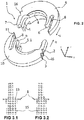
- Figure 2 shows the connection ring (1) for being mounted on a gas tap body (15) of ovens and furnaces, the gas tap body comprising a tap shaft (12) and a gas tap channel (13), wherein the connection ring comprises a first piece (9) and a second piece (10) to be coupled to each other for forming the connection ring, wherein the first and second pieces comprise locking sets (4) for throttling the tap shaft channel (13) of said gas tap body (15) in an assembled state of the connection ring. It comprises fixing keys (7) formed on this first piece (9) and second piece (10) and comprising locking levels (16).
- the connection ring comprises male tabs (11) formed on both the first piece (9) and the second piece (10) and comprising fitting surfaces (11.1) attached to said locking levels (16) in an assembled state of the connection ring, and a fastening space (8) in which said fixing keys (7) are housed in an assembled state of the connection ring, thereby enabling the coupling of the first and second piece to each other.
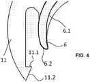
- FIG. 2 shows the retaining protrusion (6) having a convex shape and which, in an assembled state of the connection ring and due to its flexible structure, applies a force on the fixing keys (7) in the fastening space (8) for pushing the fixing keys towards the male tabs.
- said retaining protrusion (6) comprises a crescent form (6.1) surrounding the gas tap body (15) and a radiused transition surface (6.2) enabling comfortable insertion of said fixing keys (7).
- it comprises flexible male tabs (11) comprising angular transition surface (11.2) which allows comfortable insertion of fixing keys (7) into said fastening space (8).
- a lower clutch key (5) formed on both the first piece (9) and the second piece (10) clutching said tap body (15) from the lower area, and a lower clutch slot (5.1) in which said lower clutch keys (5) are housed are formed.
- connection ring (1) The way of operation of the connection ring (1) according to the invention is as follows: First of all, the first piece (9) and the second piece (10) of the connection ring (1) are coupled to each other. This coupling is ensured by housing of the fixing keys (7) in the fastening space (8) by means of the movement of the first piece (9) and the second piece (10) in opposite directions on y-axis, such as -y and +y.
- the fitting surfaces (11.1) of the male tabs (11) firstly fits into the first level (2) of the locking level (16) (see Figure 3.1 ), and in this position, the first piece (9) and the second piece (10) perform the first throttling motion, while they are not fitted on the tap shaft channel (13) of the tap body (15) yet.
- the first piece (9) and the second piece (10) are inserted/fitted into the tap shaft channel (13). In this position, the fitting surfaces (11.1) of the male tabs (11) fit into the second level (3) of the locking level (16). In this way, desired fixing operation is completed.
Landscapes
- Engineering & Computer Science (AREA)
- Chemical & Material Sciences (AREA)
- Combustion & Propulsion (AREA)
- Mechanical Engineering (AREA)
- General Engineering & Computer Science (AREA)
- Quick-Acting Or Multi-Walled Pipe Joints (AREA)
Priority Applications (1)
| Application Number | Priority Date | Filing Date | Title |
|---|---|---|---|
| PL16751689T PL3465012T3 (pl) | 2016-05-30 | 2016-05-30 | Pierścień przyłączeniowy do zaworów gazowych |
Applications Claiming Priority (1)
| Application Number | Priority Date | Filing Date | Title |
|---|---|---|---|
| PCT/TR2016/050160 WO2017209709A1 (en) | 2016-05-30 | 2016-05-30 | A connection ring for gas taps |
Publications (2)
| Publication Number | Publication Date |
|---|---|
| EP3465012A1 EP3465012A1 (en) | 2019-04-10 |
| EP3465012B1 true EP3465012B1 (en) | 2020-05-06 |
Family
ID=56686873
Family Applications (1)
| Application Number | Title | Priority Date | Filing Date |
|---|---|---|---|
| EP16751689.7A Active EP3465012B1 (en) | 2016-05-30 | 2016-05-30 | A connection ring for gas taps |
Country Status (3)
| Country | Link |
|---|---|
| EP (1) | EP3465012B1 (pl) |
| PL (1) | PL3465012T3 (pl) |
| WO (1) | WO2017209709A1 (pl) |
Families Citing this family (2)
| Publication number | Priority date | Publication date | Assignee | Title |
|---|---|---|---|---|
| WO2019129405A1 (en) * | 2017-12-25 | 2019-07-04 | Arcelik Anonim Sirketi | A cooker comprising an ignition washer |
| DE102018121487A1 (de) * | 2018-09-04 | 2020-03-05 | B. Braun Melsungen Ag | Sicherungselement zum axialen Sichern einer Welle |
Family Cites Families (7)
| Publication number | Priority date | Publication date | Assignee | Title |
|---|---|---|---|---|
| US1492561A (en) * | 1920-11-17 | 1924-05-06 | Sectional Gap Washer Corp | Washer or shim |
| US4183120A (en) * | 1978-05-19 | 1980-01-15 | Thorne George W | Encircling devices |
| US4556352A (en) * | 1984-08-08 | 1985-12-03 | American Snap Nut Association | Shaft-mounted snap lock assembly |
| ITTO20030581A1 (it) * | 2003-07-25 | 2005-01-26 | Itw Ind Components Srl | Dispositivo integrato universale di comando per fuochi |
| ITTO20070306A1 (it) * | 2007-05-04 | 2008-11-05 | Itw Ind Components S R L Co N | Dispositivo di comando includente un rubinetto gas ed un elemento di catenaria per bruciatori di un piano di cottura |
| ES2378935B1 (es) * | 2009-12-17 | 2013-03-14 | BSH Electrodomésticos España S.A. | Válvula de gas con un elemento de accionamiento para un interruptor eléctrico. |
| DE102012013992A1 (de) * | 2012-07-11 | 2014-01-16 | Getrag Getriebe- Und Zahnradfabrik Hermann Hagenmeyer Gmbh & Cie Kg | Wellen-Sicherungsscheibe |
-
2016
- 2016-05-30 WO PCT/TR2016/050160 patent/WO2017209709A1/en not_active Ceased
- 2016-05-30 PL PL16751689T patent/PL3465012T3/pl unknown
- 2016-05-30 EP EP16751689.7A patent/EP3465012B1/en active Active
Non-Patent Citations (1)
| Title |
|---|
| None * |
Also Published As
| Publication number | Publication date |
|---|---|
| WO2017209709A1 (en) | 2017-12-07 |
| EP3465012A1 (en) | 2019-04-10 |
| PL3465012T3 (pl) | 2020-09-07 |
Similar Documents
| Publication | Publication Date | Title |
|---|---|---|
| JP6356257B2 (ja) | プラグ式コネクタのためのハウジング | |
| US20150174740A1 (en) | Elastic retaining assembly and method | |
| CN103732473B (zh) | 转向装置 | |
| EP2272137B1 (en) | Locking mechanism | |
| US10503198B2 (en) | Gas knob skirt retainer | |
| CN115066810B (zh) | 具有锁定装置的插接连接器元件 | |
| US10443773B2 (en) | Push-in connector | |
| EP2913550B1 (en) | Spline lock shaft locking system | |
| US20210286397A1 (en) | Knob assembly for a cooking appliance and method of assembling | |
| EP2796730B1 (en) | Improved connector | |
| EP3465012A1 (en) | A connection ring for gas taps | |
| WO2018164728A1 (en) | Safety lockout feature for plug | |
| EP1368865B1 (en) | Connector | |
| CN112513509A (zh) | 连接两个管状物体的装置 | |
| CN107345543B (zh) | 同步器滑块及同步器 | |
| CN115133320B (zh) | 电绝缘触摸保护装置和具有这样的触摸保护装置的连接组件 | |
| CN112654796B (zh) | 用于轴向固定轴的固定元件 | |
| JP2024523737A (ja) | ロック解除が選択可能であるプラグコネクタ | |
| CN109415915A (zh) | 用于闩锁组件的撞块 | |
| WO1999041808A1 (en) | Connector assembly | |
| CN222910925U (zh) | 一种适用于燃气具电磁阀的连接结构及电磁阀组件 | |
| CN116266687B (zh) | 具有防振机构的电连接器 | |
| JP6792956B2 (ja) | 管継手アッセンブリ及び管継手用回転止め具 | |
| CN220253654U (zh) | 连接器 | |
| JP2013160296A (ja) | クリップ |
Legal Events
| Date | Code | Title | Description |
|---|---|---|---|
| STAA | Information on the status of an ep patent application or granted ep patent |
Free format text: STATUS: THE INTERNATIONAL PUBLICATION HAS BEEN MADE |
|
| PUAI | Public reference made under article 153(3) epc to a published international application that has entered the european phase |
Free format text: ORIGINAL CODE: 0009012 |
|
| STAA | Information on the status of an ep patent application or granted ep patent |
Free format text: STATUS: REQUEST FOR EXAMINATION WAS MADE |
|
| 17P | Request for examination filed |
Effective date: 20181129 |
|
| AK | Designated contracting states |
Kind code of ref document: A1 Designated state(s): AL AT BE BG CH CY CZ DE DK EE ES FI FR GB GR HR HU IE IS IT LI LT LU LV MC MK MT NL NO PL PT RO RS SE SI SK SM TR |
|
| AX | Request for extension of the european patent |
Extension state: BA ME |
|
| DAV | Request for validation of the european patent (deleted) | ||
| DAX | Request for extension of the european patent (deleted) | ||
| GRAP | Despatch of communication of intention to grant a patent |
Free format text: ORIGINAL CODE: EPIDOSNIGR1 |
|
| STAA | Information on the status of an ep patent application or granted ep patent |
Free format text: STATUS: GRANT OF PATENT IS INTENDED |
|
| INTG | Intention to grant announced |
Effective date: 20200214 |
|
| GRAS | Grant fee paid |
Free format text: ORIGINAL CODE: EPIDOSNIGR3 |
|
| GRAA | (expected) grant |
Free format text: ORIGINAL CODE: 0009210 |
|
| STAA | Information on the status of an ep patent application or granted ep patent |
Free format text: STATUS: THE PATENT HAS BEEN GRANTED |
|
| AK | Designated contracting states |
Kind code of ref document: B1 Designated state(s): AL AT BE BG CH CY CZ DE DK EE ES FI FR GB GR HR HU IE IS IT LI LT LU LV MC MK MT NL NO PL PT RO RS SE SI SK SM TR |
|
| REG | Reference to a national code |
Ref country code: GB Ref legal event code: FG4D |
|
| REG | Reference to a national code |
Ref country code: CH Ref legal event code: EP Ref country code: AT Ref legal event code: REF Ref document number: 1267373 Country of ref document: AT Kind code of ref document: T Effective date: 20200515 |
|
| REG | Reference to a national code |
Ref country code: DE Ref legal event code: R096 Ref document number: 602016035837 Country of ref document: DE |
|
| REG | Reference to a national code |
Ref country code: IE Ref legal event code: FG4D |
|
| REG | Reference to a national code |
Ref country code: LT Ref legal event code: MG4D |
|
| REG | Reference to a national code |
Ref country code: NL Ref legal event code: MP Effective date: 20200506 |
|
| PG25 | Lapsed in a contracting state [announced via postgrant information from national office to epo] |
Ref country code: NO Free format text: LAPSE BECAUSE OF FAILURE TO SUBMIT A TRANSLATION OF THE DESCRIPTION OR TO PAY THE FEE WITHIN THE PRESCRIBED TIME-LIMIT Effective date: 20200806 Ref country code: FI Free format text: LAPSE BECAUSE OF FAILURE TO SUBMIT A TRANSLATION OF THE DESCRIPTION OR TO PAY THE FEE WITHIN THE PRESCRIBED TIME-LIMIT Effective date: 20200506 Ref country code: GR Free format text: LAPSE BECAUSE OF FAILURE TO SUBMIT A TRANSLATION OF THE DESCRIPTION OR TO PAY THE FEE WITHIN THE PRESCRIBED TIME-LIMIT Effective date: 20200807 Ref country code: LT Free format text: LAPSE BECAUSE OF FAILURE TO SUBMIT A TRANSLATION OF THE DESCRIPTION OR TO PAY THE FEE WITHIN THE PRESCRIBED TIME-LIMIT Effective date: 20200506 Ref country code: PT Free format text: LAPSE BECAUSE OF FAILURE TO SUBMIT A TRANSLATION OF THE DESCRIPTION OR TO PAY THE FEE WITHIN THE PRESCRIBED TIME-LIMIT Effective date: 20200907 Ref country code: IS Free format text: LAPSE BECAUSE OF FAILURE TO SUBMIT A TRANSLATION OF THE DESCRIPTION OR TO PAY THE FEE WITHIN THE PRESCRIBED TIME-LIMIT Effective date: 20200906 Ref country code: SE Free format text: LAPSE BECAUSE OF FAILURE TO SUBMIT A TRANSLATION OF THE DESCRIPTION OR TO PAY THE FEE WITHIN THE PRESCRIBED TIME-LIMIT Effective date: 20200506 |
|
| PG25 | Lapsed in a contracting state [announced via postgrant information from national office to epo] |
Ref country code: RS Free format text: LAPSE BECAUSE OF FAILURE TO SUBMIT A TRANSLATION OF THE DESCRIPTION OR TO PAY THE FEE WITHIN THE PRESCRIBED TIME-LIMIT Effective date: 20200506 Ref country code: HR Free format text: LAPSE BECAUSE OF FAILURE TO SUBMIT A TRANSLATION OF THE DESCRIPTION OR TO PAY THE FEE WITHIN THE PRESCRIBED TIME-LIMIT Effective date: 20200506 Ref country code: LV Free format text: LAPSE BECAUSE OF FAILURE TO SUBMIT A TRANSLATION OF THE DESCRIPTION OR TO PAY THE FEE WITHIN THE PRESCRIBED TIME-LIMIT Effective date: 20200506 |
|
| REG | Reference to a national code |
Ref country code: DE Ref legal event code: R119 Ref document number: 602016035837 Country of ref document: DE |
|
| REG | Reference to a national code |
Ref country code: AT Ref legal event code: MK05 Ref document number: 1267373 Country of ref document: AT Kind code of ref document: T Effective date: 20200506 |
|
| PG25 | Lapsed in a contracting state [announced via postgrant information from national office to epo] |
Ref country code: AL Free format text: LAPSE BECAUSE OF FAILURE TO SUBMIT A TRANSLATION OF THE DESCRIPTION OR TO PAY THE FEE WITHIN THE PRESCRIBED TIME-LIMIT Effective date: 20200506 Ref country code: NL Free format text: LAPSE BECAUSE OF FAILURE TO SUBMIT A TRANSLATION OF THE DESCRIPTION OR TO PAY THE FEE WITHIN THE PRESCRIBED TIME-LIMIT Effective date: 20200506 |
|
| PG25 | Lapsed in a contracting state [announced via postgrant information from national office to epo] |
Ref country code: LI Free format text: LAPSE BECAUSE OF NON-PAYMENT OF DUE FEES Effective date: 20200531 Ref country code: SM Free format text: LAPSE BECAUSE OF FAILURE TO SUBMIT A TRANSLATION OF THE DESCRIPTION OR TO PAY THE FEE WITHIN THE PRESCRIBED TIME-LIMIT Effective date: 20200506 Ref country code: EE Free format text: LAPSE BECAUSE OF FAILURE TO SUBMIT A TRANSLATION OF THE DESCRIPTION OR TO PAY THE FEE WITHIN THE PRESCRIBED TIME-LIMIT Effective date: 20200506 Ref country code: RO Free format text: LAPSE BECAUSE OF FAILURE TO SUBMIT A TRANSLATION OF THE DESCRIPTION OR TO PAY THE FEE WITHIN THE PRESCRIBED TIME-LIMIT Effective date: 20200506 Ref country code: ES Free format text: LAPSE BECAUSE OF FAILURE TO SUBMIT A TRANSLATION OF THE DESCRIPTION OR TO PAY THE FEE WITHIN THE PRESCRIBED TIME-LIMIT Effective date: 20200506 Ref country code: CZ Free format text: LAPSE BECAUSE OF FAILURE TO SUBMIT A TRANSLATION OF THE DESCRIPTION OR TO PAY THE FEE WITHIN THE PRESCRIBED TIME-LIMIT Effective date: 20200506 Ref country code: AT Free format text: LAPSE BECAUSE OF FAILURE TO SUBMIT A TRANSLATION OF THE DESCRIPTION OR TO PAY THE FEE WITHIN THE PRESCRIBED TIME-LIMIT Effective date: 20200506 Ref country code: CH Free format text: LAPSE BECAUSE OF NON-PAYMENT OF DUE FEES Effective date: 20200531 Ref country code: DK Free format text: LAPSE BECAUSE OF FAILURE TO SUBMIT A TRANSLATION OF THE DESCRIPTION OR TO PAY THE FEE WITHIN THE PRESCRIBED TIME-LIMIT Effective date: 20200506 |
|
| PG25 | Lapsed in a contracting state [announced via postgrant information from national office to epo] |
Ref country code: SK Free format text: LAPSE BECAUSE OF FAILURE TO SUBMIT A TRANSLATION OF THE DESCRIPTION OR TO PAY THE FEE WITHIN THE PRESCRIBED TIME-LIMIT Effective date: 20200506 Ref country code: MC Free format text: LAPSE BECAUSE OF FAILURE TO SUBMIT A TRANSLATION OF THE DESCRIPTION OR TO PAY THE FEE WITHIN THE PRESCRIBED TIME-LIMIT Effective date: 20200506 |
|
| PLBE | No opposition filed within time limit |
Free format text: ORIGINAL CODE: 0009261 |
|
| STAA | Information on the status of an ep patent application or granted ep patent |
Free format text: STATUS: NO OPPOSITION FILED WITHIN TIME LIMIT |
|
| REG | Reference to a national code |
Ref country code: BE Ref legal event code: MM Effective date: 20200531 |
|
| PG25 | Lapsed in a contracting state [announced via postgrant information from national office to epo] |
Ref country code: LU Free format text: LAPSE BECAUSE OF NON-PAYMENT OF DUE FEES Effective date: 20200530 |
|
| 26N | No opposition filed |
Effective date: 20210209 |
|
| GBPC | Gb: european patent ceased through non-payment of renewal fee |
Effective date: 20200806 |
|
| PG25 | Lapsed in a contracting state [announced via postgrant information from national office to epo] |
Ref country code: FR Free format text: LAPSE BECAUSE OF NON-PAYMENT OF DUE FEES Effective date: 20200706 Ref country code: IE Free format text: LAPSE BECAUSE OF NON-PAYMENT OF DUE FEES Effective date: 20200530 |
|
| PG25 | Lapsed in a contracting state [announced via postgrant information from national office to epo] |
Ref country code: SI Free format text: LAPSE BECAUSE OF FAILURE TO SUBMIT A TRANSLATION OF THE DESCRIPTION OR TO PAY THE FEE WITHIN THE PRESCRIBED TIME-LIMIT Effective date: 20200506 Ref country code: BE Free format text: LAPSE BECAUSE OF NON-PAYMENT OF DUE FEES Effective date: 20200531 Ref country code: DE Free format text: LAPSE BECAUSE OF NON-PAYMENT OF DUE FEES Effective date: 20201201 |
|
| PG25 | Lapsed in a contracting state [announced via postgrant information from national office to epo] |
Ref country code: GB Free format text: LAPSE BECAUSE OF NON-PAYMENT OF DUE FEES Effective date: 20200806 |
|
| PG25 | Lapsed in a contracting state [announced via postgrant information from national office to epo] |
Ref country code: TR Free format text: LAPSE BECAUSE OF FAILURE TO SUBMIT A TRANSLATION OF THE DESCRIPTION OR TO PAY THE FEE WITHIN THE PRESCRIBED TIME-LIMIT Effective date: 20200506 Ref country code: MT Free format text: LAPSE BECAUSE OF FAILURE TO SUBMIT A TRANSLATION OF THE DESCRIPTION OR TO PAY THE FEE WITHIN THE PRESCRIBED TIME-LIMIT Effective date: 20200506 Ref country code: CY Free format text: LAPSE BECAUSE OF FAILURE TO SUBMIT A TRANSLATION OF THE DESCRIPTION OR TO PAY THE FEE WITHIN THE PRESCRIBED TIME-LIMIT Effective date: 20200506 |
|
| PG25 | Lapsed in a contracting state [announced via postgrant information from national office to epo] |
Ref country code: MK Free format text: LAPSE BECAUSE OF FAILURE TO SUBMIT A TRANSLATION OF THE DESCRIPTION OR TO PAY THE FEE WITHIN THE PRESCRIBED TIME-LIMIT Effective date: 20200506 |
|
| PGFP | Annual fee paid to national office [announced via postgrant information from national office to epo] |
Ref country code: PL Payment date: 20250514 Year of fee payment: 10 |
|
| PGFP | Annual fee paid to national office [announced via postgrant information from national office to epo] |
Ref country code: IT Payment date: 20250522 Year of fee payment: 10 |
|
| PGFP | Annual fee paid to national office [announced via postgrant information from national office to epo] |
Ref country code: BG Payment date: 20250527 Year of fee payment: 10 |