EP3464984B1 - Inline cycle fuse - Google Patents
Inline cycle fuse Download PDFInfo
- Publication number
- EP3464984B1 EP3464984B1 EP17731367.3A EP17731367A EP3464984B1 EP 3464984 B1 EP3464984 B1 EP 3464984B1 EP 17731367 A EP17731367 A EP 17731367A EP 3464984 B1 EP3464984 B1 EP 3464984B1
- Authority
- EP
- European Patent Office
- Prior art keywords
- pressure vessel
- pipe
- conduit wall
- conduit
- cavity
- Prior art date
- Legal status (The legal status is an assumption and is not a legal conclusion. Google has not performed a legal analysis and makes no representation as to the accuracy of the status listed.)
- Active
Links
Images

Classifications
-
- F—MECHANICAL ENGINEERING; LIGHTING; HEATING; WEAPONS; BLASTING
- F17—STORING OR DISTRIBUTING GASES OR LIQUIDS
- F17C—VESSELS FOR CONTAINING OR STORING COMPRESSED, LIQUEFIED OR SOLIDIFIED GASES; FIXED-CAPACITY GAS-HOLDERS; FILLING VESSELS WITH, OR DISCHARGING FROM VESSELS, COMPRESSED, LIQUEFIED, OR SOLIDIFIED GASES
- F17C13/00—Details of vessels or of the filling or discharging of vessels
- F17C13/12—Arrangements or mounting of devices for preventing or minimising the effect of explosion ; Other safety measures
- F17C13/123—Arrangements or mounting of devices for preventing or minimising the effect of explosion ; Other safety measures for gas bottles, cylinders or reservoirs for tank vehicles or for railway tank wagons
-
- G—PHYSICS
- G01—MEASURING; TESTING
- G01M—TESTING STATIC OR DYNAMIC BALANCE OF MACHINES OR STRUCTURES; TESTING OF STRUCTURES OR APPARATUS, NOT OTHERWISE PROVIDED FOR
- G01M3/00—Investigating fluid-tightness of structures
- G01M3/02—Investigating fluid-tightness of structures by using fluid or vacuum
- G01M3/04—Investigating fluid-tightness of structures by using fluid or vacuum by detecting the presence of fluid at the leakage point
-
- F—MECHANICAL ENGINEERING; LIGHTING; HEATING; WEAPONS; BLASTING
- F15—FLUID-PRESSURE ACTUATORS; HYDRAULICS OR PNEUMATICS IN GENERAL
- F15B—SYSTEMS ACTING BY MEANS OF FLUIDS IN GENERAL; FLUID-PRESSURE ACTUATORS, e.g. SERVOMOTORS; DETAILS OF FLUID-PRESSURE SYSTEMS, NOT OTHERWISE PROVIDED FOR
- F15B1/00—Installations or systems with accumulators; Supply reservoir or sump assemblies
- F15B1/02—Installations or systems with accumulators
- F15B1/04—Accumulators
- F15B1/08—Accumulators using a gas cushion; Gas charging devices; Indicators or floats therefor
- F15B1/083—Accumulators using a gas cushion; Gas charging devices; Indicators or floats therefor the accumulator having a fusible plug
-
- F—MECHANICAL ENGINEERING; LIGHTING; HEATING; WEAPONS; BLASTING
- F16—ENGINEERING ELEMENTS AND UNITS; GENERAL MEASURES FOR PRODUCING AND MAINTAINING EFFECTIVE FUNCTIONING OF MACHINES OR INSTALLATIONS; THERMAL INSULATION IN GENERAL
- F16L—PIPES; JOINTS OR FITTINGS FOR PIPES; SUPPORTS FOR PIPES, CABLES OR PROTECTIVE TUBING; MEANS FOR THERMAL INSULATION IN GENERAL
- F16L55/00—Devices or appurtenances for use in, or in connection with, pipes or pipe systems
- F16L55/07—Arrangement or mounting of devices, e.g. valves, for venting or aerating or draining
-
- F—MECHANICAL ENGINEERING; LIGHTING; HEATING; WEAPONS; BLASTING
- F16—ENGINEERING ELEMENTS AND UNITS; GENERAL MEASURES FOR PRODUCING AND MAINTAINING EFFECTIVE FUNCTIONING OF MACHINES OR INSTALLATIONS; THERMAL INSULATION IN GENERAL
- F16L—PIPES; JOINTS OR FITTINGS FOR PIPES; SUPPORTS FOR PIPES, CABLES OR PROTECTIVE TUBING; MEANS FOR THERMAL INSULATION IN GENERAL
- F16L57/00—Protection of pipes or objects of similar shape against external or internal damage or wear
-
- F—MECHANICAL ENGINEERING; LIGHTING; HEATING; WEAPONS; BLASTING
- F16—ENGINEERING ELEMENTS AND UNITS; GENERAL MEASURES FOR PRODUCING AND MAINTAINING EFFECTIVE FUNCTIONING OF MACHINES OR INSTALLATIONS; THERMAL INSULATION IN GENERAL
- F16L—PIPES; JOINTS OR FITTINGS FOR PIPES; SUPPORTS FOR PIPES, CABLES OR PROTECTIVE TUBING; MEANS FOR THERMAL INSULATION IN GENERAL
- F16L58/00—Protection of pipes or pipe fittings against corrosion or incrustation
-
- G—PHYSICS
- G01—MEASURING; TESTING
- G01D—MEASURING NOT SPECIALLY ADAPTED FOR A SPECIFIC VARIABLE; ARRANGEMENTS FOR MEASURING TWO OR MORE VARIABLES NOT COVERED IN A SINGLE OTHER SUBCLASS; TARIFF METERING APPARATUS; MEASURING OR TESTING NOT OTHERWISE PROVIDED FOR
- G01D3/00—Indicating or recording apparatus with provision for the special purposes referred to in the subgroups
- G01D3/08—Indicating or recording apparatus with provision for the special purposes referred to in the subgroups with provision for safeguarding the apparatus, e.g. against abnormal operation, against breakdown
-
- G—PHYSICS
- G01—MEASURING; TESTING
- G01M—TESTING STATIC OR DYNAMIC BALANCE OF MACHINES OR STRUCTURES; TESTING OF STRUCTURES OR APPARATUS, NOT OTHERWISE PROVIDED FOR
- G01M3/00—Investigating fluid-tightness of structures
- G01M3/007—Leak detector calibration, standard leaks
-
- G—PHYSICS
- G01—MEASURING; TESTING
- G01N—INVESTIGATING OR ANALYSING MATERIALS BY DETERMINING THEIR CHEMICAL OR PHYSICAL PROPERTIES
- G01N29/00—Investigating or analysing materials by the use of ultrasonic, sonic or infrasonic waves; Visualisation of the interior of objects by transmitting ultrasonic or sonic waves through the object
- G01N29/14—Investigating or analysing materials by the use of ultrasonic, sonic or infrasonic waves; Visualisation of the interior of objects by transmitting ultrasonic or sonic waves through the object using acoustic emission techniques
-
- G—PHYSICS
- G01—MEASURING; TESTING
- G01N—INVESTIGATING OR ANALYSING MATERIALS BY DETERMINING THEIR CHEMICAL OR PHYSICAL PROPERTIES
- G01N29/00—Investigating or analysing materials by the use of ultrasonic, sonic or infrasonic waves; Visualisation of the interior of objects by transmitting ultrasonic or sonic waves through the object
- G01N29/22—Details, e.g. general constructional or apparatus details
- G01N29/227—Details, e.g. general constructional or apparatus details related to high pressure, tension or stress conditions
-
- G—PHYSICS
- G05—CONTROLLING; REGULATING
- G05B—CONTROL OR REGULATING SYSTEMS IN GENERAL; FUNCTIONAL ELEMENTS OF SUCH SYSTEMS; MONITORING OR TESTING ARRANGEMENTS FOR SUCH SYSTEMS OR ELEMENTS
- G05B23/00—Testing or monitoring of control systems or parts thereof
- G05B23/02—Electric testing or monitoring
- G05B23/0205—Electric testing or monitoring by means of a monitoring system capable of detecting and responding to faults
- G05B23/0259—Electric testing or monitoring by means of a monitoring system capable of detecting and responding to faults characterized by the response to fault detection
- G05B23/0283—Predictive maintenance, e.g. involving the monitoring of a system and, based on the monitoring results, taking decisions on the maintenance schedule of the monitored system; Estimating remaining useful life [RUL]
-
- G—PHYSICS
- G06—COMPUTING OR CALCULATING; COUNTING
- G06Q—INFORMATION AND COMMUNICATION TECHNOLOGY [ICT] SPECIALLY ADAPTED FOR ADMINISTRATIVE, COMMERCIAL, FINANCIAL, MANAGERIAL OR SUPERVISORY PURPOSES; SYSTEMS OR METHODS SPECIALLY ADAPTED FOR ADMINISTRATIVE, COMMERCIAL, FINANCIAL, MANAGERIAL OR SUPERVISORY PURPOSES, NOT OTHERWISE PROVIDED FOR
- G06Q10/00—Administration; Management
- G06Q10/04—Forecasting or optimisation specially adapted for administrative or management purposes, e.g. linear programming or "cutting stock problem"
-
- G—PHYSICS
- G06—COMPUTING OR CALCULATING; COUNTING
- G06Q—INFORMATION AND COMMUNICATION TECHNOLOGY [ICT] SPECIALLY ADAPTED FOR ADMINISTRATIVE, COMMERCIAL, FINANCIAL, MANAGERIAL OR SUPERVISORY PURPOSES; SYSTEMS OR METHODS SPECIALLY ADAPTED FOR ADMINISTRATIVE, COMMERCIAL, FINANCIAL, MANAGERIAL OR SUPERVISORY PURPOSES, NOT OTHERWISE PROVIDED FOR
- G06Q10/00—Administration; Management
- G06Q10/20—Administration of product repair or maintenance
-
- F—MECHANICAL ENGINEERING; LIGHTING; HEATING; WEAPONS; BLASTING
- F16—ENGINEERING ELEMENTS AND UNITS; GENERAL MEASURES FOR PRODUCING AND MAINTAINING EFFECTIVE FUNCTIONING OF MACHINES OR INSTALLATIONS; THERMAL INSULATION IN GENERAL
- F16L—PIPES; JOINTS OR FITTINGS FOR PIPES; SUPPORTS FOR PIPES, CABLES OR PROTECTIVE TUBING; MEANS FOR THERMAL INSULATION IN GENERAL
- F16L2201/00—Special arrangements for pipe couplings
- F16L2201/30—Detecting leaks
-
- F—MECHANICAL ENGINEERING; LIGHTING; HEATING; WEAPONS; BLASTING
- F16—ENGINEERING ELEMENTS AND UNITS; GENERAL MEASURES FOR PRODUCING AND MAINTAINING EFFECTIVE FUNCTIONING OF MACHINES OR INSTALLATIONS; THERMAL INSULATION IN GENERAL
- F16L—PIPES; JOINTS OR FITTINGS FOR PIPES; SUPPORTS FOR PIPES, CABLES OR PROTECTIVE TUBING; MEANS FOR THERMAL INSULATION IN GENERAL
- F16L39/00—Joints or fittings for double-walled or multi-channel pipes or pipe assemblies
-
- F—MECHANICAL ENGINEERING; LIGHTING; HEATING; WEAPONS; BLASTING
- F16—ENGINEERING ELEMENTS AND UNITS; GENERAL MEASURES FOR PRODUCING AND MAINTAINING EFFECTIVE FUNCTIONING OF MACHINES OR INSTALLATIONS; THERMAL INSULATION IN GENERAL
- F16L—PIPES; JOINTS OR FITTINGS FOR PIPES; SUPPORTS FOR PIPES, CABLES OR PROTECTIVE TUBING; MEANS FOR THERMAL INSULATION IN GENERAL
- F16L41/00—Branching pipes; Joining pipes to walls
- F16L41/02—Branch units, e.g. made in one piece, welded, riveted
- F16L41/021—T- or cross-pieces
-
- F—MECHANICAL ENGINEERING; LIGHTING; HEATING; WEAPONS; BLASTING
- F16—ENGINEERING ELEMENTS AND UNITS; GENERAL MEASURES FOR PRODUCING AND MAINTAINING EFFECTIVE FUNCTIONING OF MACHINES OR INSTALLATIONS; THERMAL INSULATION IN GENERAL
- F16L—PIPES; JOINTS OR FITTINGS FOR PIPES; SUPPORTS FOR PIPES, CABLES OR PROTECTIVE TUBING; MEANS FOR THERMAL INSULATION IN GENERAL
- F16L9/00—Rigid pipes
- F16L9/18—Double-walled pipes; Multi-channel pipes or pipe assemblies
-
- F—MECHANICAL ENGINEERING; LIGHTING; HEATING; WEAPONS; BLASTING
- F17—STORING OR DISTRIBUTING GASES OR LIQUIDS
- F17C—VESSELS FOR CONTAINING OR STORING COMPRESSED, LIQUEFIED OR SOLIDIFIED GASES; FIXED-CAPACITY GAS-HOLDERS; FILLING VESSELS WITH, OR DISCHARGING FROM VESSELS, COMPRESSED, LIQUEFIED, OR SOLIDIFIED GASES
- F17C2205/00—Vessel construction, in particular mounting arrangements, attachments or identifications means
- F17C2205/03—Fluid connections, filters, valves, closure means or other attachments
- F17C2205/0302—Fittings, valves, filters, or components in connection with the gas storage device
- F17C2205/0311—Closure means
- F17C2205/0314—Closure means breakable, e.g. with burst discs
-
- F—MECHANICAL ENGINEERING; LIGHTING; HEATING; WEAPONS; BLASTING
- F17—STORING OR DISTRIBUTING GASES OR LIQUIDS
- F17C—VESSELS FOR CONTAINING OR STORING COMPRESSED, LIQUEFIED OR SOLIDIFIED GASES; FIXED-CAPACITY GAS-HOLDERS; FILLING VESSELS WITH, OR DISCHARGING FROM VESSELS, COMPRESSED, LIQUEFIED, OR SOLIDIFIED GASES
- F17C2260/00—Purposes of gas storage and gas handling
- F17C2260/03—Dealing with losses
- F17C2260/035—Dealing with losses of fluid
- F17C2260/036—Avoiding leaks
-
- F—MECHANICAL ENGINEERING; LIGHTING; HEATING; WEAPONS; BLASTING
- F17—STORING OR DISTRIBUTING GASES OR LIQUIDS
- F17C—VESSELS FOR CONTAINING OR STORING COMPRESSED, LIQUEFIED OR SOLIDIFIED GASES; FIXED-CAPACITY GAS-HOLDERS; FILLING VESSELS WITH, OR DISCHARGING FROM VESSELS, COMPRESSED, LIQUEFIED, OR SOLIDIFIED GASES
- F17C2260/00—Purposes of gas storage and gas handling
- F17C2260/03—Dealing with losses
- F17C2260/035—Dealing with losses of fluid
- F17C2260/038—Detecting leaked fluid
-
- Y—GENERAL TAGGING OF NEW TECHNOLOGICAL DEVELOPMENTS; GENERAL TAGGING OF CROSS-SECTIONAL TECHNOLOGIES SPANNING OVER SEVERAL SECTIONS OF THE IPC; TECHNICAL SUBJECTS COVERED BY FORMER USPC CROSS-REFERENCE ART COLLECTIONS [XRACs] AND DIGESTS
- Y02—TECHNOLOGIES OR APPLICATIONS FOR MITIGATION OR ADAPTATION AGAINST CLIMATE CHANGE
- Y02E—REDUCTION OF GREENHOUSE GAS [GHG] EMISSIONS, RELATED TO ENERGY GENERATION, TRANSMISSION OR DISTRIBUTION
- Y02E60/00—Enabling technologies; Technologies with a potential or indirect contribution to GHG emissions mitigation
- Y02E60/30—Hydrogen technology
- Y02E60/32—Hydrogen storage
Definitions
- Pressure vessels are commonly used for containing a variety of gases or fluids under pressure, such as hydrogen, oxygen, natural gas, nitrogen, propane and other fuels, for example.
- pressure vessels can be of any size or configuration.
- the vessels can be heavy or light, single-use (e.g., disposable), reusable, subjected to high pressures (greater than 50 psi, for example), low pressures (less than 50 psi, for example), or used for storing fluids at elevated or cryogenic temperatures, for example.
- Suitable pressure vessel shell materials include metals, such as steel; or composites, which may be formed of laminated layers of wound fiberglass filaments or other synthetic filaments bonded together by a thermo-setting or thermoplastic resin.
- a liner or bladder is often disposed within a pressure vessel shell to seal the vessel, thereby serving as a fluid permeation barrier.
- pressure vessels have limited lifetimes, and it is desirable to remove a pressure vessel from service before it fails, as failures can be catastrophic and cause damage or injury.
- Both cyclic fatigue and static fatigue (stress rupture) contribute to the fatigue load, and thus the failure, of pressure vessels.
- the calendar life of a pressure vessel, or the number of fatigue cycles over a specific pressure range is commonly used to determine when to remove a vessel from service.
- the pressure ranges and number of cycles applied to the pressure vessel are inconsistent and/or unknown.
- the interaction between cyclic fatigue life and static fatigue life is not well understood. The effects of cycling combine in unknown ways with the effects of the duration the pressure vessel spends at full pressure without cycling.
- WO 2017/087376 discloses a failure indicator apparatus in which a primary pressure vessel is connected to a source of pressurized fluid, a supplemental pressure vessel is fluidly connected in-line with the line connecting the source and the primary pressure vessel, wherein the supplemental pressure vessel is more susceptible to fatigue failure than the primary vessel, so that the supplemental vessel fails before fatigue failure of the primary pressure vessel occurs.
- the document WO 2016/001542 discloses a device having an accumulator provided with a gas chamber containing a pressurized gas, and a hydraulic chamber containing a fluid, where the gas chamber is separated from the hydraulic chamber by an elastic diaphragm.
- An external pipeline is connected to the gas chamber, where the pipeline is provided with a shock-sensitive security system designed to open in the event of unwanted forces applied to the pipeline.
- the security system includes a pusher for receiving the shock and opening the pipeline.
- this disclosure describes a system according to claim 1.
- the system includes: a pressure vessel; a fluid source; a line coupled to the pressure vessel and to the fluid source, wherein pressurized fluid flows through the line; an apparatus including: a pipe connected in the line so that the pressurized fluid flows through the pipe between the pressure vessel and the fluid source, the pipe having a conduit wall that is exposed to pressure cycling of the pressure vessel; a containment structure including a cavity separated from an interior of the pipe by a portion of the conduit wall; and the portion of the conduit wall having a weakness configured such that the conduit wall fails at the weakness to permit the fluid to flow from the interior of the pipe into the cavity of the containment structure; and a sensor configured to determine a value of a physical property in the cavity; and a controller in signal communication with the sensor and configured to detect a change in the value.
- this disclosure describes a method of predicting impending failure of a pressure vessel according to claim 7.
- the method includes: fluidly connecting the pressure vessel to a source of pressurized fluid via a line so that pressurized fluid flows through the line; fluidly connecting an apparatus to the line between the pressure vessel and the source, the apparatus including: a pipe connected in the line so that the pressurized fluid flows through the pipe, the pipe having a conduit wall that is exposed to pressure cycling of the pressure vessel; and a containment structure including a cavity separated from an interior of the pipe by a portion of the conduit wall; determining a first value of a physical property in the cavity of the containment structure; experiencing a failure of the conduit wall that permits the pressurized fluid to flow from the interior of the pipe into the cavity; determining a second value of the physical property in the cavity; detecting a difference between the first and second values; and calibrating the failure of the conduit wall to occur before an estimated useful life of the pressure vessel.
- a fuse is positioned in-line with a fluid flow, for instance, along a flow line into or out of a pressure vessel.
- the fuse is constructed to safely indicate a maximum-allowed cycle load.
- a fuse includes a containment cavity and a small conduit that is scored or machined to have a weakness such as a notch- or divot-like flaw in the portion of the conduit that runs through the containment cavity.
- a fuse includes a conduit that is formed with a material and/or structure designed to fail before expected failure of a connected pressure vessel. Fluid flows into and out of the pressure vessel through the conduit.
- the conduit After exposure to a maximum-allowed cycle load, stresses due to pressure cycling cause the conduit to fail, such as at the location of the flaw.
- stresses due to pressure cycling cause the conduit to fail, such as at the location of the flaw.
- the conduit When the conduit is breached, it vents into the containment cavity until a physical property such as the internal pressure of the cavity matches that of the conduit.
- the increased pressure in the cavity may be used to trigger alarms indicating that the maximum cycle load has been reached. Further, the leak may be safely routed to a vent system.
- the disclosed systems and methods allow a user to predict impending failure of a connected pressure vessel.
- the fuse is calibrated to fail at a predetermined percentage of a pressure vessel's estimated useful life.
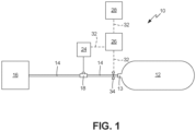
- FIG. 1 shows a schematic illustration of an exemplary embodiment of a pressure vessel failure indicator system 10, which includes pressure vessel 12 coupled (e.g., in fluid communication) to a conduit such as source line 14.
- Source line 14 may be, for example, metallic and/or polymer conduit or tubing.
- Pressure vessel 12 is configured to contain a liquid or gaseous fluid under pressure and include metallic and/or composite construction. Suitable metals include, for example, stainless steel and nickel alloys. Suitable composite materials include, for example, fiberglass or carbon fiber.
- Source line 14 allows fluidic communication of pressure vessel 12 with a source of pressurized fluid 16, which provides the fluid with which pressure vessel 12 is filled.
- Valve 34 is disposed on source line 14 between fluid source 16 and pressure vessel 12. When valve 34 is open, pressure vessel 12 and fluid source 16 are in fluid communication. Conversely, when valve 34 is closed, no flow occurs between fluid source 16 and pressure vessel 12.
- the fuse 18 is disposed in series with pressure vessel 12 with respect to the source 16.
- pressure vessel 12 is coupled to line 14 via boss 13 of pressure vessel 12, but any coupling mechanism that allows fluid in line 14 to selectively flow into and out of pressure vessel 12 may be used. Details relevant to the formation of an exemplary pressure vessel 12 are disclosed in U.S. Patent No. 4,838,971 , entitled “Filament Winding Process and Apparatus;” and U.S. Patent No. 4,369,894 , entitled “Filament Wound Vessels”.
- an apparatus such as fuse 18 may be designed to have a predetermined time-to-failure (e.g., life expectancy duration) that is less than the expected time-to-failure of pressure vessel 12 by an amount that allows fuse 18 to signal an impending failure of pressure vessel 12.
- the expected life duration of pressure vessel 12 may be defined by a number of pressure cycles and/or a time duration at one or more static pressures, for example, before structural integrity of pressure vessel 18 is compromised enough to cause failure.
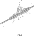
- an exemplary embodiment of fuse 18 includes conduit 36a configured for fluid connection to conduit 14 such that fluid flowing through conduit 14 also flows through conduit 36a.
- conduit 36 is illustrated as a cylindrical conduit in FIGS. 3-5 , it is contemplated that other pipe forms and shapes may also be used.
- conduit 36a has a conduit wall 44a.
- At least one weakness 20, such as a notch or divot, may be located on conduit wall 44a. Thus, mechanical failure initiates at weakness 20 before occurring at another location on fuse 18.
- weakness 20 is scored or machined into conduit 36 at a precise depth in a metallic conduit wall 44.
- Weakness 20 is calibrated so that conduit wall 44a breaks before pressure vessel 12 fails, such as at a pre-determined percentage of the pressure vessel's estimated useful life. It is contemplated that any weakness 20 may be employed, such as, for example, an area of conduit wall 44a having a different thickness, composition, structure, susceptibility to corrosion, or other property, rendering the weakness more susceptible to failure than a remainder of fuse 18.
- One or more sensors 24 may be located in, on, or connected to fuse 18 and be configured to detect one or more conditions of fuse 18.
- sensor 24 may be configured to detect one or more physical conditions in fuse 18, such as temperature, pressure, acoustic emissions, conductivity, or any other indicator of failure of conduit wall 44, such as at weakness 20.
- Sensor 24 may be connected to controller 26 via signal communication line 32.
- controller 26 can include known processors, microprocessors, microcontrollers, and programmable logic controllers (PLC), for example.
- controller 26 runs software and thereby communicates with external devices, such as sensor 24, indicator 28, valve 34 and any other external devices, via signal communication lines 32.
- signal communication can be performed via interfaces (not shown), such as one using a standard RS-485/Modbus protocol, using hard wired and/or wireless communication means.
- Controller 26 receives a signal from a sensor 24 regarding one or more sensed values of a physical condition and runs software (not shown) to determine whether failure of conduit 36 has occurred, as a function of the sensed value(s).
- one or both of indicator 28 and valve 34 are in signal communication with controller 26 via signal communication lines 32.
- Controller 26 is configured to respond to a failure of source line 14, for example, by triggering indicator 28 to relay a signal to a user and/or removing pressure vessel 12 from service.
- triggering indicator 28 includes sending a signal from controller 26 to actuate a visible and/or audible signal or alarm to users of breach of source line 14 at conduit 36.
- removing pressure vessel 12 from service includes disconnecting pressure vessel 12 from fluid source 16, such as by sending a signal from controller 26 to automatically close valve 34 between pressure vessel 12 and fluid source 16, thereby stopping fluid flow between fluid source 16 and pressure vessel 12.
- pressure vessel 12 may be manually dismounted or otherwise removed from service, either before or after an alert of failure, for inspection.
- fuse 18 is formed integrally with source line 14.
- fuse 18 is formed as a separate component that can be connected to segments of source line 14, such as at fasteners 22, which include nuts and washers threadably attached to shaft 30 in an exemplary embodiment.
- fuse 18 includes conduit 36a having weakness 20 formed on conduit wall 44a. Gas flowing through source line 14 also flows through conduit 36.
- the configuration of weakness 20 and the material of conduit 36a are calibrated so that conduit 36a breaks at weakness 20 at a pre-determined pressure cycle load passing through source line 14, wherein such a pre-determined pressure cycle load is calculated to be reflective of an expected life duration of pressure vessel 12 attached to source line 14.
- conduit 36a at weakness 20 Upon failure of conduit 36a at weakness 20, the gas flowing in source line 14 escapes from an interior of conduit 36a into cavity 38 of containment structure 40.
- sensor 24 is connected to cavity 38 of fuse 18, such as via a connection at aperture 42, to sense one or more values of physical conditions in cavity 38. While a particular configuration of containment structure 40 is illustrated, it is contemplated that containment structure 40 may differ in size and shape from the illustrated embodiment. However, whatever the configuration of containment structure 40, fluid communication between source line 14 and cavity 38 is provided by the rupture of conduit 36a, such as at weakness 20. While it appears in FIGS. 2 and 3 that containment structure 40 is open at aperture 42, in an exemplary embodiment, sensor 24 is attached to fuse 18 at aperture 42, such as by a coupler or other known connection.
- "failure" of conduit 36 includes rupture thereof or a smaller breach that results in fluid leakage therefrom of a larger than threshold amount.
- a threshold amount may be set by a user and/or determined by software run by controller 26 that takes into account factors including, for example, the sensed physical conditions whose values are determined by one or more sensors 24.
- Sensor 24 is configured to determine a value of a physical property in cavity 38.
- Exemplary values of physical properties include, for example, a temperature reading, a pressure value, a conductivity value, an acoustic emission wavelength or frequency, and electrical capacitance or resistance value, an optical value, and a substance concentration percentage.
- Controller 26 is in signal communication with sensor 24 via signal communication line 32. Controller 26 receives multiple readings from sensor 24, such as at timed intervals, for example, and is configured to detect a change in the values detected by sensor 24.
- the pressurized fluid in system 10 is a cryogenic fluid.
- Sensor 24 returns a first temperature value of the cavity 38 and a second temperature value of the cavity 38.
- Controller 26 calculates a difference between the first and second values. Controller 26 may run software or otherwise be programmed to determine that rupture of the conduit wall 44 at weakness 20 has occurred if the difference is above a pre-determined threshold difference. In another method, even more simply, controller 26 may determine that failure at fuse 18 has occurred if any of the sensed temperature values is below or above pre-determined one or more threshold temperature values.
- controller 26 may determine that failure of source line 14 has occurred if sensor 24 returns a concentration value of hydrogen in the cavity 38 of containment structure 40 that is above a pre-determined threshold hydrogen concentration, or that a difference in substance concentration values exceeds a pre-determined threshold difference. In yet another example, controller 26 may determine that failure of source line 14 has occurred if sensor 24 returns a pressure value of gas in the cavity 38 of containment structure 40 that is above a pre-determined threshold pressure, or that a difference in measured pressure values exceeds a pre-determined threshold difference. Software run by controller 26 may also be programmed to take into consideration any combination of physical condition values returned by sensors 24 to determine whether failure of source line 14 has occurred.
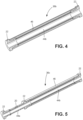
- FIGS. 4-5 illustrate exemplary embodiments of other configurations of conduits 36 that can be used in fuse 18.
- conduit 36b includes a conduit wall 44b that may be formed of a material such as a polymer.
- Overwrap layer 46 formed surrounding conduit wall 44b may be formed as a filament-wound composite material, which may be similar in composition and construction to a composite shell material of the protected pressure vessel 12.
- the overwrap layer 46 is configured in its composition and/or structure to fail before an expected failure of the pressure vessel 12.
- conduit 36b of FIG. 4 does not have a discrete point of weakness, but rather could fail at any point along conduit wall 44b and/or overwrap layer 46.
- a containment structure 40 for use with conduit 36b may include a larger cavity 38 that envelops all portions of conduit 36b between fasteners 22.
- a conduit 36b as shown in FIG. 4 may be most useful for predicting a static fatigue limit on the composite shell of pressure vessel 12.
- conduit 36a of FIG. 3 having a discrete machined weakness 20 on a conduit wall 44a, may be most useful for predicting failure with respect to a predetermined number of pressurization cycles.
- Conduit 36c of FIG. 5 combines the features of conduit 36a of FIG. 3 and conduit 36b of FIG. 4 .
- a containment structure 40 for use with conduit 36b would, in an exemplary embodiment, include a cavity 38a that encompasses the entire conduit 36c between the outer fasteners 22. It is expected that in use, conduit wall 44b would be breached when a static fatigue limit of overwrap layer 46 is reached, which is calibrated to be before a point of failure of a composite shell of pressure vessel 12. Moreover, it is expected that conduit wall 44a would be breached at weakness 20 when a set number of cycles of pressurization have been experience at conduit wall 44a. Thus, the combination conduit 36c is effective to protect the pressure vessel 12 against expected static fatigue and pressurization cycle limits.
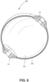
- FIG. 6 shows a conduit 36d which is similar in composition to conduit 36b of FIG. 4 .
- the structural shape of conduit wall 44c and overwrap layer 46c are not tubular structures as shown in FIGS. 3-5 . Rather, as shown in FIG. 6 , a conduit 36d can have a spherical geometry.
- the conduit 36d of FIG. 6 can also be combined with a pressure cycle predictive device similar to conduit wall 44a with weakness 20 formed therein.
- a containment structure 40 would surround conduit 36d and could be outfitted with other components such as sensor 24, controller 26, indicator 28 and signal communication line 32 as discussed above. Such a system, however, is not covered by the scope of the claims.
- the geometry of a conduit 36 can be used to generate stress failure locations in the conduit wall 44c and/or the overwrap layer 46c that perform similarly to the weakness 20 of conduit wall 44a.
- the disclosed fuses 18 having different conduits 36 have been described as being including a containment structure 40 configured to operate as described with reference to failure indicator system 10 of FIG. 1 , it is also contemplated that the disclosed conduits 36 could additionally or alternatively be placed in fluid communication with a venting system. Such a venting system could safely and controllable release the pressurized fluid from a pressure vessel 12 and/or fluid source 16 to prevent an uncontrolled release of fluid or rupture of the pressure vessel.
Landscapes
- Engineering & Computer Science (AREA)
- General Engineering & Computer Science (AREA)
- Physics & Mathematics (AREA)
- General Physics & Mathematics (AREA)
- Business, Economics & Management (AREA)
- Mechanical Engineering (AREA)
- Human Resources & Organizations (AREA)
- Economics (AREA)
- Strategic Management (AREA)
- Tourism & Hospitality (AREA)
- General Business, Economics & Management (AREA)
- Theoretical Computer Science (AREA)
- Entrepreneurship & Innovation (AREA)
- Marketing (AREA)
- Operations Research (AREA)
- Quality & Reliability (AREA)
- Pathology (AREA)
- Biochemistry (AREA)
- Immunology (AREA)
- General Health & Medical Sciences (AREA)
- Health & Medical Sciences (AREA)
- Life Sciences & Earth Sciences (AREA)
- Chemical & Material Sciences (AREA)
- Analytical Chemistry (AREA)
- Fluid Mechanics (AREA)
- Development Economics (AREA)
- Game Theory and Decision Science (AREA)
- Acoustics & Sound (AREA)
- Automation & Control Theory (AREA)
- Investigating Strength Of Materials By Application Of Mechanical Stress (AREA)
- Measuring Fluid Pressure (AREA)
- Filling Or Discharging Of Gas Storage Vessels (AREA)
- Examining Or Testing Airtightness (AREA)
- Pipeline Systems (AREA)
- Testing Of Devices, Machine Parts, Or Other Structures Thereof (AREA)
- Investigating, Analyzing Materials By Fluorescence Or Luminescence (AREA)
- Pressure Vessels And Lids Thereof (AREA)
Applications Claiming Priority (2)
| Application Number | Priority Date | Filing Date | Title |
|---|---|---|---|
| US201662346195P | 2016-06-06 | 2016-06-06 | |
| PCT/US2017/035942 WO2017214031A1 (en) | 2016-06-06 | 2017-06-05 | Inline cycle fuse |
Publications (3)
| Publication Number | Publication Date |
|---|---|
| EP3464984A1 EP3464984A1 (en) | 2019-04-10 |
| EP3464984B1 true EP3464984B1 (en) | 2023-07-05 |
| EP3464984C0 EP3464984C0 (en) | 2023-07-05 |
Family
ID=59078194
Family Applications (1)
| Application Number | Title | Priority Date | Filing Date |
|---|---|---|---|
| EP17731367.3A Active EP3464984B1 (en) | 2016-06-06 | 2017-06-05 | Inline cycle fuse |
Country Status (12)
| Country | Link |
|---|---|
| US (3) | US10481133B2 (enExample) |
| EP (1) | EP3464984B1 (enExample) |
| JP (1) | JP6882344B2 (enExample) |
| KR (1) | KR102411015B1 (enExample) |
| CN (1) | CN109312887B (enExample) |
| AU (1) | AU2017278131A1 (enExample) |
| BR (1) | BR112018075059B1 (enExample) |
| CA (1) | CA3022483C (enExample) |
| ES (1) | ES2956067T3 (enExample) |
| PL (1) | PL3464984T3 (enExample) |
| RU (1) | RU2742185C2 (enExample) |
| WO (1) | WO2017214031A1 (enExample) |
Families Citing this family (11)
| Publication number | Priority date | Publication date | Assignee | Title |
|---|---|---|---|---|
| US10288223B2 (en) * | 2015-11-20 | 2019-05-14 | Hexagon Technology As | Failure indicator supplemental vessel for primary vessel |
| EP4227585A1 (en) * | 2018-11-05 | 2023-08-16 | Watts Regulator Co. | Fluid discharge event detector |
| CN109827081B (zh) * | 2019-02-28 | 2020-12-11 | 昆明理工大学 | 一种基于声学主动检测的埋地排水管道堵塞故障及管道三通件诊断方法 |
| US11440399B2 (en) | 2019-03-22 | 2022-09-13 | Agility Fuel Systems Llc | Fuel system mountable to a vehicle frame |
| US20200347992A1 (en) | 2019-05-02 | 2020-11-05 | Agility Fuel Systems Llc | Polymeric liner based gas cylinder with reduced permeability |
| JP7424722B2 (ja) * | 2019-08-09 | 2024-01-30 | 三桜工業株式会社 | 配管の分岐構造 |
| CN112461928A (zh) * | 2020-11-17 | 2021-03-09 | 广州多浦乐电子科技股份有限公司 | 工件表面超声相控阵自动检测装置 |
| JP7623136B2 (ja) * | 2020-12-24 | 2025-01-28 | 川崎重工業株式会社 | 液化ガス用真空断熱配管ユニットおよび液化ガス用真空断熱配管の破損検知方法 |
| CN113236889A (zh) * | 2021-03-27 | 2021-08-10 | 邹城兖矿泰德工贸有限公司 | 提引水接头 |
| US11913581B2 (en) * | 2021-07-20 | 2024-02-27 | FirstElement Fuel, Inc. | Control conduit for LH2 offloading |
| CN114497673A (zh) * | 2021-08-30 | 2022-05-13 | 陕西奥林波斯电力能源有限责任公司 | 一种制作大容量电池的电芯及其组装工艺 |
Family Cites Families (41)
| Publication number | Priority date | Publication date | Assignee | Title |
|---|---|---|---|---|
| US1938475A (en) | 1933-12-05 | Choke | ||
| US1426956A (en) | 1920-10-08 | 1922-08-22 | Baker Mfg Corp | Acid line for paper mills |
| US1962168A (en) | 1930-07-30 | 1934-06-12 | Smith Corp A O | Lined pressure vessel |
| US1977177A (en) | 1931-03-19 | 1934-10-16 | Flores Luis De | Method of anticipating failure in oil treating systems |
| US1975832A (en) | 1931-09-03 | 1934-10-09 | Florez Luis De | Conduit |
| US2233403A (en) | 1938-12-01 | 1941-03-04 | Hobart C Dickinson | Method for indicating the wear on bearings and other surfaces |
| US2726683A (en) | 1951-08-30 | 1955-12-13 | Standard Oil Co | Pipe blind with failure indicator |
| US2937520A (en) * | 1956-02-03 | 1960-05-24 | Foster Wheeler Corp | Liquid leak transmitting device |
| US3922999A (en) | 1973-11-02 | 1975-12-02 | Charles E Meginnis | Sight glass with wear indicating device |
| JPS542185A (en) * | 1977-06-07 | 1979-01-09 | Hitachi Ltd | Leakage detector of corrosive gas |
| US4369894A (en) | 1980-12-29 | 1983-01-25 | Brunswick Corporation | Filament wound vessels |
| US4448062A (en) | 1981-10-22 | 1984-05-15 | Conoco Inc. | Method and apparatus for erosion detection and location in hydrocarbon production systems and the like |
| JPS6081600A (ja) * | 1983-10-12 | 1985-05-09 | Roudoushiyou Sangyo Anzen Kenkyusho | 爆発被害抑制用破裂板装置 |
| US4642557A (en) | 1984-08-10 | 1987-02-10 | Combustion Engineering, Inc. | Method of and apparatus for detecting erosion |
| US4617822A (en) | 1985-08-20 | 1986-10-21 | Cerline Ceramic Corporation | Tell-tale wear monitor for pipes having wear resistant inner linings |
| US4838971A (en) | 1987-02-19 | 1989-06-13 | Brunswick Corporation | Filament winding process and apparatus |
| US4922748A (en) | 1987-11-18 | 1990-05-08 | Joram Hopenfeld | Method for monitoring thinning of pipe walls and piping component for use therewith |
| US4779453A (en) | 1987-11-18 | 1988-10-25 | Joram Hopenfeld | Method for monitoring thinning of pipe walls |
| US5024755A (en) | 1989-11-22 | 1991-06-18 | Bird Escher Wyss | Cone wear detection |
| JP2557753B2 (ja) | 1991-04-02 | 1996-11-27 | テイサン株式会社 | 圧力調整器のガス出流れ現象防止装置 |
| FR2711797B1 (fr) | 1993-10-29 | 1996-01-12 | Inst Francais Du Petrole | Dispositif de surveillance du vieillissement de fluides. |
| US5929325A (en) * | 1998-01-12 | 1999-07-27 | The Dumont Company, Inc. | System for containing and handling toxic gas and methods for containing and handling same |
| US6080982A (en) | 1998-05-13 | 2000-06-27 | The United States Of America As Represented By The Secretary Of The Navy | Embedded wear sensor |
| JP2000130896A (ja) * | 1998-10-29 | 2000-05-12 | Sanden Corp | 安全装置を備えた空調装置 |
| US6131443A (en) | 1999-08-04 | 2000-10-17 | Duncan; William P. | Corrosion monitor |
| BRPI0212062B1 (pt) * | 2001-08-24 | 2015-06-02 | Bs & B Safety Systems Inc | Sistemas de monitoramento de contentor pressurizado e de dispositivo de redução de pressão ligado de modo vedante em contentor pressurizado e métodos de monitoramento de condições experimentadas por contentor pressurizado e por dispositivo de redução de pressão |
| JP2003172500A (ja) | 2001-12-03 | 2003-06-20 | Kokan Drum Co Ltd | 気体格納装置、気体供給装置、気体の搬送方法及び気体格納装置の取扱い方法 |
| US6945098B2 (en) | 2003-06-25 | 2005-09-20 | Krebs Engineers Corporation | Hydrocyclone wear-detection sensor |
| WO2007002266A2 (en) * | 2005-06-22 | 2007-01-04 | Purdue Research Foundation | Structures with integral life-sensing capability |
| WO2007111052A1 (ja) * | 2006-03-28 | 2007-10-04 | Mitsui Mining & Smelting Co., Ltd. | 流体識別装置および流体識別方法 |
| CN200968468Y (zh) * | 2006-07-26 | 2007-10-31 | 张玉卿 | 带有压力测量接口的管接头 |
| JP2009121510A (ja) * | 2007-11-12 | 2009-06-04 | Toyota Motor Corp | バルブアッセンブリ及び圧力容器 |
| RU81284U1 (ru) * | 2008-10-14 | 2009-03-10 | Анатолий Васильевич Салохин | Многослойный сосуд шаровой формы |
| EP2503314A1 (en) | 2011-03-25 | 2012-09-26 | ABB Oy | Anticipatory failure indicator and fluid cooling arrangement |
| DE102012207179A1 (de) * | 2012-04-30 | 2013-10-31 | Evonik Industries Ag | Verschleißindikatorsystem für Offshore-Korrosionsschutz-Umhüllungssysteme |
| RU2548398C1 (ru) * | 2014-01-09 | 2015-04-20 | Федеральное государственное бюджетное образовательное учреждение высшего профессионального образования "Национальный минерально-сырьевой университет "Горный" | Устройство для фильтрации и отбора проб жидкостей в сосудах под давлением |
| FR3023330B1 (fr) | 2014-07-01 | 2017-11-24 | Technoboost | Accumulateur de pression hydraulique equipe d’un systeme de securite externe comportant une canalisation |
| JP5871033B2 (ja) * | 2014-07-08 | 2016-03-01 | 住友金属鉱山株式会社 | 蒸気配管破損検知装置 |
| CA2860682C (en) | 2014-08-22 | 2015-08-18 | Westport Power Inc. | Gaseous fluid supply system with subsystem for isolating a storage vessel from an end user |
| JP2016191638A (ja) * | 2015-03-31 | 2016-11-10 | 株式会社東芝 | 漏洩検知システム及び漏洩検知方法 |
| US10288223B2 (en) * | 2015-11-20 | 2019-05-14 | Hexagon Technology As | Failure indicator supplemental vessel for primary vessel |
-
2017
- 2017-06-05 RU RU2018145317A patent/RU2742185C2/ru active
- 2017-06-05 EP EP17731367.3A patent/EP3464984B1/en active Active
- 2017-06-05 ES ES17731367T patent/ES2956067T3/es active Active
- 2017-06-05 WO PCT/US2017/035942 patent/WO2017214031A1/en not_active Ceased
- 2017-06-05 BR BR112018075059-0A patent/BR112018075059B1/pt active IP Right Grant
- 2017-06-05 AU AU2017278131A patent/AU2017278131A1/en not_active Abandoned
- 2017-06-05 PL PL17731367.3T patent/PL3464984T3/pl unknown
- 2017-06-05 JP JP2018563817A patent/JP6882344B2/ja active Active
- 2017-06-05 CA CA3022483A patent/CA3022483C/en active Active
- 2017-06-05 KR KR1020187038065A patent/KR102411015B1/ko active Active
- 2017-06-05 US US15/613,899 patent/US10481133B2/en active Active
- 2017-06-05 CN CN201780034457.6A patent/CN109312887B/zh active Active
-
2019
- 2019-10-08 US US16/596,174 patent/US10837946B2/en active Active
-
2020
- 2020-09-29 US US17/036,383 patent/US11293828B2/en active Active
Also Published As
| Publication number | Publication date |
|---|---|
| US20210010979A1 (en) | 2021-01-14 |
| BR112018075059B1 (pt) | 2022-05-31 |
| KR20190015728A (ko) | 2019-02-14 |
| CA3022483A1 (en) | 2017-12-14 |
| RU2742185C2 (ru) | 2021-02-03 |
| RU2018145317A (ru) | 2020-07-10 |
| EP3464984A1 (en) | 2019-04-10 |
| CN109312887B (zh) | 2021-05-14 |
| JP2019523872A (ja) | 2019-08-29 |
| US10481133B2 (en) | 2019-11-19 |
| US20200088690A1 (en) | 2020-03-19 |
| KR102411015B1 (ko) | 2022-06-20 |
| BR112018075059A2 (pt) | 2019-03-06 |
| ES2956067T3 (es) | 2023-12-12 |
| EP3464984C0 (en) | 2023-07-05 |
| US20170350867A1 (en) | 2017-12-07 |
| CA3022483C (en) | 2023-08-08 |
| WO2017214031A1 (en) | 2017-12-14 |
| CN109312887A (zh) | 2019-02-05 |
| US11293828B2 (en) | 2022-04-05 |
| AU2017278131A1 (en) | 2018-11-15 |
| JP6882344B2 (ja) | 2021-06-02 |
| PL3464984T3 (pl) | 2024-02-26 |
| US10837946B2 (en) | 2020-11-17 |
| RU2018145317A3 (enExample) | 2020-09-09 |
Similar Documents
| Publication | Publication Date | Title |
|---|---|---|
| US11293828B2 (en) | Inline cycle fuse | |
| US10962173B2 (en) | Failure indicator supplemental vessel for primary vessel | |
| KR101517552B1 (ko) | 압력용기 이력관리장치 및 그의 충진방법 | |
| JP2019523872A5 (enExample) | ||
| US8800588B2 (en) | Glass bulb thermally-activated pressure relief device, safety inspection method, and equipment | |
| EP4502451A1 (en) | Storage tank | |
| US20250043924A1 (en) | Storage tank | |
| US20250043912A1 (en) | Storage tank | |
| Matvienko et al. | Reliability and cold resistance of thin-walled structures at low ambient temperatures | |
| EP2662603A1 (en) | Non-metallic pipe or conduit with early detection means for detecting failures, detection system and method | |
| WO2018101840A1 (en) | A hose arrangement and a method for testing the integrity of a hose unit of a hose arrangement |
Legal Events
| Date | Code | Title | Description |
|---|---|---|---|
| STAA | Information on the status of an ep patent application or granted ep patent |
Free format text: STATUS: UNKNOWN |
|
| STAA | Information on the status of an ep patent application or granted ep patent |
Free format text: STATUS: THE INTERNATIONAL PUBLICATION HAS BEEN MADE |
|
| PUAI | Public reference made under article 153(3) epc to a published international application that has entered the european phase |
Free format text: ORIGINAL CODE: 0009012 |
|
| STAA | Information on the status of an ep patent application or granted ep patent |
Free format text: STATUS: REQUEST FOR EXAMINATION WAS MADE |
|
| 17P | Request for examination filed |
Effective date: 20181031 |
|
| AK | Designated contracting states |
Kind code of ref document: A1 Designated state(s): AL AT BE BG CH CY CZ DE DK EE ES FI FR GB GR HR HU IE IS IT LI LT LU LV MC MK MT NL NO PL PT RO RS SE SI SK SM TR |
|
| AX | Request for extension of the european patent |
Extension state: BA ME |
|
| DAV | Request for validation of the european patent (deleted) | ||
| DAX | Request for extension of the european patent (deleted) | ||
| STAA | Information on the status of an ep patent application or granted ep patent |
Free format text: STATUS: EXAMINATION IS IN PROGRESS |
|
| 17Q | First examination report despatched |
Effective date: 20210512 |
|
| GRAP | Despatch of communication of intention to grant a patent |
Free format text: ORIGINAL CODE: EPIDOSNIGR1 |
|
| STAA | Information on the status of an ep patent application or granted ep patent |
Free format text: STATUS: GRANT OF PATENT IS INTENDED |
|
| INTG | Intention to grant announced |
Effective date: 20221209 |
|
| GRAS | Grant fee paid |
Free format text: ORIGINAL CODE: EPIDOSNIGR3 |
|
| GRAA | (expected) grant |
Free format text: ORIGINAL CODE: 0009210 |
|
| STAA | Information on the status of an ep patent application or granted ep patent |
Free format text: STATUS: THE PATENT HAS BEEN GRANTED |
|
| AK | Designated contracting states |
Kind code of ref document: B1 Designated state(s): AL AT BE BG CH CY CZ DE DK EE ES FI FR GB GR HR HU IE IS IT LI LT LU LV MC MK MT NL NO PL PT RO RS SE SI SK SM TR |
|
| REG | Reference to a national code |
Ref country code: CH Ref legal event code: EP |
|
| REG | Reference to a national code |
Ref country code: AT Ref legal event code: REF Ref document number: 1585133 Country of ref document: AT Kind code of ref document: T Effective date: 20230715 |
|
| REG | Reference to a national code |
Ref country code: DE Ref legal event code: R096 Ref document number: 602017070933 Country of ref document: DE |
|
| REG | Reference to a national code |
Ref country code: IE Ref legal event code: FG4D |
|
| U01 | Request for unitary effect filed |
Effective date: 20230801 |
|
| U07 | Unitary effect registered |
Designated state(s): AT BE BG DE DK EE FI FR IT LT LU LV MT NL PT SE SI Effective date: 20230804 |
|
| REG | Reference to a national code |
Ref country code: NO Ref legal event code: T2 Effective date: 20230705 |
|
| REG | Reference to a national code |
Ref country code: LT Ref legal event code: MG9D |
|
| REG | Reference to a national code |
Ref country code: ES Ref legal event code: FG2A Ref document number: 2956067 Country of ref document: ES Kind code of ref document: T3 Effective date: 20231212 |
|
| PG25 | Lapsed in a contracting state [announced via postgrant information from national office to epo] |
Ref country code: GR Free format text: LAPSE BECAUSE OF FAILURE TO SUBMIT A TRANSLATION OF THE DESCRIPTION OR TO PAY THE FEE WITHIN THE PRESCRIBED TIME-LIMIT Effective date: 20231006 |
|
| PG25 | Lapsed in a contracting state [announced via postgrant information from national office to epo] |
Ref country code: IS Free format text: LAPSE BECAUSE OF FAILURE TO SUBMIT A TRANSLATION OF THE DESCRIPTION OR TO PAY THE FEE WITHIN THE PRESCRIBED TIME-LIMIT Effective date: 20231105 |
|
| PG25 | Lapsed in a contracting state [announced via postgrant information from national office to epo] |
Ref country code: RS Free format text: LAPSE BECAUSE OF FAILURE TO SUBMIT A TRANSLATION OF THE DESCRIPTION OR TO PAY THE FEE WITHIN THE PRESCRIBED TIME-LIMIT Effective date: 20230705 Ref country code: IS Free format text: LAPSE BECAUSE OF FAILURE TO SUBMIT A TRANSLATION OF THE DESCRIPTION OR TO PAY THE FEE WITHIN THE PRESCRIBED TIME-LIMIT Effective date: 20231105 Ref country code: HR Free format text: LAPSE BECAUSE OF FAILURE TO SUBMIT A TRANSLATION OF THE DESCRIPTION OR TO PAY THE FEE WITHIN THE PRESCRIBED TIME-LIMIT Effective date: 20230705 Ref country code: GR Free format text: LAPSE BECAUSE OF FAILURE TO SUBMIT A TRANSLATION OF THE DESCRIPTION OR TO PAY THE FEE WITHIN THE PRESCRIBED TIME-LIMIT Effective date: 20231006 |
|
| REG | Reference to a national code |
Ref country code: DE Ref legal event code: R097 Ref document number: 602017070933 Country of ref document: DE |
|
| PG25 | Lapsed in a contracting state [announced via postgrant information from national office to epo] |
Ref country code: SM Free format text: LAPSE BECAUSE OF FAILURE TO SUBMIT A TRANSLATION OF THE DESCRIPTION OR TO PAY THE FEE WITHIN THE PRESCRIBED TIME-LIMIT Effective date: 20230705 Ref country code: RO Free format text: LAPSE BECAUSE OF FAILURE TO SUBMIT A TRANSLATION OF THE DESCRIPTION OR TO PAY THE FEE WITHIN THE PRESCRIBED TIME-LIMIT Effective date: 20230705 Ref country code: CZ Free format text: LAPSE BECAUSE OF FAILURE TO SUBMIT A TRANSLATION OF THE DESCRIPTION OR TO PAY THE FEE WITHIN THE PRESCRIBED TIME-LIMIT Effective date: 20230705 Ref country code: SK Free format text: LAPSE BECAUSE OF FAILURE TO SUBMIT A TRANSLATION OF THE DESCRIPTION OR TO PAY THE FEE WITHIN THE PRESCRIBED TIME-LIMIT Effective date: 20230705 |
|
| PLBE | No opposition filed within time limit |
Free format text: ORIGINAL CODE: 0009261 |
|
| STAA | Information on the status of an ep patent application or granted ep patent |
Free format text: STATUS: NO OPPOSITION FILED WITHIN TIME LIMIT |
|
| 26N | No opposition filed |
Effective date: 20240408 |
|
| U20 | Renewal fee for the european patent with unitary effect paid |
Year of fee payment: 8 Effective date: 20240627 |
|
| PG25 | Lapsed in a contracting state [announced via postgrant information from national office to epo] |
Ref country code: MC Free format text: LAPSE BECAUSE OF FAILURE TO SUBMIT A TRANSLATION OF THE DESCRIPTION OR TO PAY THE FEE WITHIN THE PRESCRIBED TIME-LIMIT Effective date: 20230705 |
|
| REG | Reference to a national code |
Ref country code: CH Ref legal event code: PL |
|
| PG25 | Lapsed in a contracting state [announced via postgrant information from national office to epo] |
Ref country code: CH Free format text: LAPSE BECAUSE OF NON-PAYMENT OF DUE FEES Effective date: 20240630 |
|
| PGFP | Annual fee paid to national office [announced via postgrant information from national office to epo] |
Ref country code: PL Payment date: 20250522 Year of fee payment: 9 |
|
| PGFP | Annual fee paid to national office [announced via postgrant information from national office to epo] |
Ref country code: GB Payment date: 20250627 Year of fee payment: 9 |
|
| PGFP | Annual fee paid to national office [announced via postgrant information from national office to epo] |
Ref country code: NO Payment date: 20250627 Year of fee payment: 9 |
|
| PGFP | Annual fee paid to national office [announced via postgrant information from national office to epo] |
Ref country code: TR Payment date: 20250526 Year of fee payment: 9 |
|
| PGFP | Annual fee paid to national office [announced via postgrant information from national office to epo] |
Ref country code: IE Payment date: 20250627 Year of fee payment: 9 |
|
| U20 | Renewal fee for the european patent with unitary effect paid |
Year of fee payment: 9 Effective date: 20250628 |
|
| PGFP | Annual fee paid to national office [announced via postgrant information from national office to epo] |
Ref country code: ES Payment date: 20250701 Year of fee payment: 9 |
|
| PG25 | Lapsed in a contracting state [announced via postgrant information from national office to epo] |
Ref country code: CY Free format text: LAPSE BECAUSE OF FAILURE TO SUBMIT A TRANSLATION OF THE DESCRIPTION OR TO PAY THE FEE WITHIN THE PRESCRIBED TIME-LIMIT; INVALID AB INITIO Effective date: 20170605 |