EP3464882B1 - Schwimmende windenergieanlage mit einer mehrzahl von energiewandlungseinheiten - Google Patents
Schwimmende windenergieanlage mit einer mehrzahl von energiewandlungseinheiten Download PDFInfo
- Publication number
- EP3464882B1 EP3464882B1 EP17725156.8A EP17725156A EP3464882B1 EP 3464882 B1 EP3464882 B1 EP 3464882B1 EP 17725156 A EP17725156 A EP 17725156A EP 3464882 B1 EP3464882 B1 EP 3464882B1
- Authority
- EP
- European Patent Office
- Prior art keywords
- wind turbine
- energy conversion
- conversion units
- tower
- cable system
- Prior art date
- Legal status (The legal status is an assumption and is not a legal conclusion. Google has not performed a legal analysis and makes no representation as to the accuracy of the status listed.)
- Active
Links
- 238000006243 chemical reaction Methods 0.000 title claims description 57
- 230000010363 phase shift Effects 0.000 claims description 2
- 230000001105 regulatory effect Effects 0.000 claims 1
- 208000034699 Vitreous floaters Diseases 0.000 description 12
- 238000009434 installation Methods 0.000 description 12
- 238000005452 bending Methods 0.000 description 4
- 239000000463 material Substances 0.000 description 4
- 238000000545 stagnation point adsorption reflectometry Methods 0.000 description 4
- XLYOFNOQVPJJNP-UHFFFAOYSA-N water Substances O XLYOFNOQVPJJNP-UHFFFAOYSA-N 0.000 description 4
- 238000004873 anchoring Methods 0.000 description 1
- 230000005465 channeling Effects 0.000 description 1
- 238000010276 construction Methods 0.000 description 1
- 230000001419 dependent effect Effects 0.000 description 1
- 230000008092 positive effect Effects 0.000 description 1
- 238000010008 shearing Methods 0.000 description 1
- 230000009182 swimming Effects 0.000 description 1
Images


Classifications
-
- F—MECHANICAL ENGINEERING; LIGHTING; HEATING; WEAPONS; BLASTING
- F03—MACHINES OR ENGINES FOR LIQUIDS; WIND, SPRING, OR WEIGHT MOTORS; PRODUCING MECHANICAL POWER OR A REACTIVE PROPULSIVE THRUST, NOT OTHERWISE PROVIDED FOR
- F03D—WIND MOTORS
- F03D13/00—Assembly, mounting or commissioning of wind motors; Arrangements specially adapted for transporting wind motor components
- F03D13/20—Arrangements for mounting or supporting wind motors; Masts or towers for wind motors
- F03D13/25—Arrangements for mounting or supporting wind motors; Masts or towers for wind motors specially adapted for offshore installation
-
- B—PERFORMING OPERATIONS; TRANSPORTING
- B63—SHIPS OR OTHER WATERBORNE VESSELS; RELATED EQUIPMENT
- B63B—SHIPS OR OTHER WATERBORNE VESSELS; EQUIPMENT FOR SHIPPING
- B63B1/00—Hydrodynamic or hydrostatic features of hulls or of hydrofoils
- B63B1/02—Hydrodynamic or hydrostatic features of hulls or of hydrofoils deriving lift mainly from water displacement
- B63B1/10—Hydrodynamic or hydrostatic features of hulls or of hydrofoils deriving lift mainly from water displacement with multiple hulls
- B63B1/107—Semi-submersibles; Small waterline area multiple hull vessels and the like, e.g. SWATH
-
- F—MECHANICAL ENGINEERING; LIGHTING; HEATING; WEAPONS; BLASTING
- F03—MACHINES OR ENGINES FOR LIQUIDS; WIND, SPRING, OR WEIGHT MOTORS; PRODUCING MECHANICAL POWER OR A REACTIVE PROPULSIVE THRUST, NOT OTHERWISE PROVIDED FOR
- F03D—WIND MOTORS
- F03D1/00—Wind motors with rotation axis substantially parallel to the air flow entering the rotor
- F03D1/02—Wind motors with rotation axis substantially parallel to the air flow entering the rotor having a plurality of rotors
-
- B—PERFORMING OPERATIONS; TRANSPORTING
- B63—SHIPS OR OTHER WATERBORNE VESSELS; RELATED EQUIPMENT
- B63B—SHIPS OR OTHER WATERBORNE VESSELS; EQUIPMENT FOR SHIPPING
- B63B35/00—Vessels or similar floating structures specially adapted for specific purposes and not otherwise provided for
- B63B35/44—Floating buildings, stores, drilling platforms, or workshops, e.g. carrying water-oil separating devices
- B63B2035/4433—Floating structures carrying electric power plants
- B63B2035/446—Floating structures carrying electric power plants for converting wind energy into electric energy
-
- F—MECHANICAL ENGINEERING; LIGHTING; HEATING; WEAPONS; BLASTING
- F05—INDEXING SCHEMES RELATING TO ENGINES OR PUMPS IN VARIOUS SUBCLASSES OF CLASSES F01-F04
- F05B—INDEXING SCHEME RELATING TO WIND, SPRING, WEIGHT, INERTIA OR LIKE MOTORS, TO MACHINES OR ENGINES FOR LIQUIDS COVERED BY SUBCLASSES F03B, F03D AND F03G
- F05B2240/00—Components
- F05B2240/20—Rotors
- F05B2240/21—Rotors for wind turbines
- F05B2240/221—Rotors for wind turbines with horizontal axis
- F05B2240/2213—Rotors for wind turbines with horizontal axis and with the rotor downwind from the yaw pivot axis
-
- F—MECHANICAL ENGINEERING; LIGHTING; HEATING; WEAPONS; BLASTING
- F05—INDEXING SCHEMES RELATING TO ENGINES OR PUMPS IN VARIOUS SUBCLASSES OF CLASSES F01-F04
- F05B—INDEXING SCHEME RELATING TO WIND, SPRING, WEIGHT, INERTIA OR LIKE MOTORS, TO MACHINES OR ENGINES FOR LIQUIDS COVERED BY SUBCLASSES F03B, F03D AND F03G
- F05B2240/00—Components
- F05B2240/90—Mounting on supporting structures or systems
- F05B2240/93—Mounting on supporting structures or systems on a structure floating on a liquid surface
-
- Y—GENERAL TAGGING OF NEW TECHNOLOGICAL DEVELOPMENTS; GENERAL TAGGING OF CROSS-SECTIONAL TECHNOLOGIES SPANNING OVER SEVERAL SECTIONS OF THE IPC; TECHNICAL SUBJECTS COVERED BY FORMER USPC CROSS-REFERENCE ART COLLECTIONS [XRACs] AND DIGESTS
- Y02—TECHNOLOGIES OR APPLICATIONS FOR MITIGATION OR ADAPTATION AGAINST CLIMATE CHANGE
- Y02E—REDUCTION OF GREENHOUSE GAS [GHG] EMISSIONS, RELATED TO ENERGY GENERATION, TRANSMISSION OR DISTRIBUTION
- Y02E10/00—Energy generation through renewable energy sources
- Y02E10/70—Wind energy
- Y02E10/72—Wind turbines with rotation axis in wind direction
-
- Y—GENERAL TAGGING OF NEW TECHNOLOGICAL DEVELOPMENTS; GENERAL TAGGING OF CROSS-SECTIONAL TECHNOLOGIES SPANNING OVER SEVERAL SECTIONS OF THE IPC; TECHNICAL SUBJECTS COVERED BY FORMER USPC CROSS-REFERENCE ART COLLECTIONS [XRACs] AND DIGESTS
- Y02—TECHNOLOGIES OR APPLICATIONS FOR MITIGATION OR ADAPTATION AGAINST CLIMATE CHANGE
- Y02E—REDUCTION OF GREENHOUSE GAS [GHG] EMISSIONS, RELATED TO ENERGY GENERATION, TRANSMISSION OR DISTRIBUTION
- Y02E10/00—Energy generation through renewable energy sources
- Y02E10/70—Wind energy
- Y02E10/727—Offshore wind turbines
Definitions
- the invention relates to a floating wind turbine with a plurality of energy conversion units.
- the invention relates to a floating wind turbine with a floating foundation, a tower arranged on the floating foundation, at least two booms extending from the tower, one energy conversion unit arranged at the free end of each boom, and one connecting the foundation with the energy conversion units and the energy conversion units with one another cable system.
- Floating wind turbines that have a floating foundation, ie a floating foundation, usually have a structure with a tower arranged on a floating foundation, which has, for example, an energy conversion unit consisting of a rotor, a rotor bearing, a gearbox and a generator; see. GB 2 489 158 A , DE 10 2014 109 212 A1 .
- a floating wind turbine with two rotors is known, which are mounted on a floating foundation designed as a "ballasted SPAR".
- the two energy conversion units are attached to the free ends of two cantilevers that are mounted on the SPAR and connected to each other via guying.
- the turbines are designed as leeward runners and should align themselves independently into the wind.
- a bearing is arranged in the underwater area around the spar, which must have a diameter in the range of 8-10 m for the system sizes in question. Such bearings are not available at the moment and if so, they can only be produced with great effort and expense.
- the floating structure designed as a semi-submersible is not only immersed in the water at one point, but at points distributed spatially in one plane. This means that the swimming stability is much greater and the draft is much lower and the entire structure has a torsional rigidity due to its spatial horizontal extent and can therefore be stably tracked in the water to changes in wind direction.
- a Y-structure is used in the underwater area, at the three ends of which three buoyancy bodies (“floaters ”) are arranged. At the upper ends of these floaters outside of the water zone, the anchoring of the cable system is routed to the energy conversion units. There is an additional guying between the two energy conversion units, which bears the weight of the two Records energy conversion units.
- the two guy lines from the two systems to the windward floater serve to absorb the thrust loads generated by the rotors and to transfer them to the floater and Y-structure.
- the two cantilevers that carry the energy conversion units at the respective ends are only slightly stressed by bending moments.
- the guyings arranged below the two energy conversion units have the task of absorbing the reverse thrust when braking the system and channeling it into the floaters arranged on the leeward side.
- the cable system is pre-stressed to such an extent that a cable is not relieved of any load and is no longer pre-stressed.
- the floaters are preferably arranged in the inclination of the individual guy lines. Seen from the side, the windward floater is inclined towards the tower at the angle of the windward guy lines.
- the lee floaters are also inclined towards the tower at the angle of the lee guy lines.
- the pre-tensioning of the guyings linked to each energy conversion unit is adjusted in such a way that the resulting force from all pre-tensioning acts exactly in the axis of the cantilever. As a result of this configuration, no bending moments are introduced into the cantilever structure, only compressive forces.
- the position of the pivot points of the guyings that converge on the system must be selected in such a way that low structural loads are generated at the shortest possible distances. It is advantageous to let the guy ropes run together at one point.
- the inclined position of the floaters also results in advantageous load transfer behavior.
- the wave loads on the one hand together with the loads of the guying are (partly) compensated by the buoyancy forces on the floater, so that the Y-foundation is less loaded and does not have to be dimensioned as much.
- the bending moment in the Y foundation can be further reduced by the targeted flooding of the Y foundation chambers.
- a wind turbine which has a floating foundation designed as a semi-submersible, a tower arranged on the floating foundation, at least two booms extending from the tower, an energy conversion unit arranged at the free end of each boom, and a foundation with the energy conversion units and the Has energy conversion units interconnecting cable system, wherein the cable system has a bias, the amount of which is greater than the expected operation of the wind turbine, the bias counteracting loads.
- the cable system is specially designed in such a way that the shear forces acting on the tower, the boom and the energy conversion units are conducted into the foundation via the prestressed cables.
- the pre-tension must therefore be so great that no rope can slack at any time.
- the cable system can consist of a single cable.
- the cable system preferably consists of a plurality of cables.
- the force vector resulting from the prestressing of the cable system lies in the axis of the cantilevers on average over time when the wind energy installation is used.
- the floating foundation is in the form of a Y-shaped platform with one long arm and two short arms, with the tower located at the juncture of the three arms.
- the wind energy installation is particularly preferably designed as a leeward rotor and the tower is inclined to the leeward side.
- a further advantageous embodiment is achieved when at least two energy conversion units are arranged above the free end of the short arms.
- the cable system is designed in particular in such a way that it is articulated at the free end of the long arm and/or at the free ends of the short arms.
- the cable system is only articulated at the free end of the long arm, with the energy conversion units also being connected to the free ends of the short arms by means of supports.
- the floating foundation has a buoyancy body firmly connected to the foundation at the free ends of its arms on its side facing the tower.
- These buoyant bodies are particularly preferably arranged in such a way that the longitudinal axis of each buoyant body is aligned with an energy conversion unit in at least one plane.
- the floating wind turbine is equipped with two energy conversion units, each with a two-blade rotor, the longitudinal axis of the rotor blades of the two energy conversion units being controlled with a phase shift of 90° relative to one another during operation.
- the direction of rotation of the two rotors is designed in opposite directions, so that the gyroscopic forces on the overall structure are balanced.
- the advantage of the invention lies, among other things, in the fact that an offshore wind energy installation can be provided whose overall output is made up of a number of individual installations.
- common medium-power plants are used, which have already been tested and are built in series at low cost, so that individual plants with lower power can be used, which also already have a corresponding approval. This significantly reduces the amount of work and time required to set up the wind energy installation according to the invention.
- FIG. 1 shows a first exemplary embodiment of a particularly preferably configured wind power plant according to the invention in a perspective view from windward.
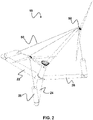
- the subsequent illustrations Figures 2 to 5 show the same wind turbine in the other views mentioned above.
- the wind turbine 10 shown has a floating foundation 20 designed as a semi-submersible, with a tower 30 arranged on the floating foundation 20 and two booms 40 extending from the tower 30.
- An energy conversion unit 50 is arranged at the free end of each boom 40, with finally a Foundation 20 with energy conversion units 50 and energy conversion units 50 interconnecting cable system 60 formed from a plurality of cables for introducing the shear forces acting on tower 30, boom 40 and energy conversion units 50 into foundation 20 and cable system 60 is prestressed has, the magnitude of which is greater than the loads that are to be expected during operation of the wind energy installation 10 and counteract the prestressing.
- the cable system 60 is designed in such a way that the force vector resulting from the prestressing of the cable system 60 lies on the axis of the boom 40 on average over time when the wind energy installation 10 is used.
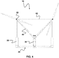
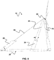
- the floating foundation 20 is formed as a Y-shaped platform having one long arm 22 and two short arms 24,26, with the tower 30 being located at the junction of the three arms 22,24,26.
- the tower 30 can be designed as a buoyant body 28 (“floater”).
- the cable system 60 can be attached directly to the foundation 20 or indirectly connected to the foundation 20 in that the cable system 60 is connected to the buoyancy bodies 28 arranged at the free ends of the foundation 20 .
- the figures show that the wind turbine 10 is designed as a lee rotor and the tower 30 is inclined to the lee side. This results in the possibility of arranging the energy conversion units 50 in such a way that the energy conversion units 50 are each arranged above the free end of a short arm 24 , 26 .
- each buoyant body 28 is aligned with an energy conversion unit 50 in at least one plane, so that an optimal introduction of force into the structures of the wind turbine 10 results.
- the wind energy installation 10 is designed in such a way that the two rotors of the energy conversion units 50 rotate in opposite directions. Overall, this configuration has a positive effect on the dynamic behavior of the floating wind energy installation 10 since the gyroscopic forces are compensated.
- the rotor blades are aligned out of phase with one another during operation—in the exemplary embodiment shown, the blades of the energy conversion units 50 are therefore arranged out of phase with one another by 90°.
- FIG. 6 shows a second exemplary embodiment of a particularly preferably configured wind energy plant according to the invention in a perspective view from windward.
- the subsequent illustrations Figures 7 to 10 show the same wind turbine in the other views mentioned above.
- the second embodiment differs from that in FIGS Figures 1 to 5 shown embodiment characterized in that the cable system is articulated at the free end of the long arm 22 of the foundation 20 and the energy conversion units 50 are connected by means of supports 70 to the free ends of the short arms 24, 26.
- the cables 60 connecting the energy conversion units 50 to the free ends of the short arms 24, 26 are therefore replaced by supports 70 which are incompressible and torsionally rigid, particularly with respect to their longitudinal axis.
- This configuration supports the introduction of the shearing forces acting on the energy conversion units 50 into the foundation 20, but means an increased material requirement in relation to the first exemplary embodiment. However, this increased material requirement is entirely justified depending on the wind loads occurring in certain regions, with the cable system 60, which connects the long arm 22 of the foundation 20 to the energy conversion units 50 and the energy conversion units 50 to one another, still having the advantages according to the invention.
- FIG. 12 shows a third exemplary embodiment of a particularly preferred wind energy installation according to the invention in a perspective view from windward.
- the subsequent illustrations Figures 12 to 15 show the same wind turbine in the other views mentioned above.
- the tower 30 is extended beyond the starting point of the two booms 40 and carries a further energy conversion unit 50 at its end.
- This third energy conversion unit 50 arranged on the tower 30 is preferably of identical design to the other two energy conversion units 50 .
- the third energy conversion unit 50 can also be designed with a 3-blade rotor, for example, with the energy conversion units arranged on the arms 40 being equipped with a 2-blade rotor.
- the cable system 60 of this exemplary embodiment is in any case designed to be more complex in that the foundation 20 is braced with each energy conversion unit 50 and the energy conversion units 50 are braced against one another by means of cables 60 .
Description
- Die Erfindung betrifft eine schwimmende Windenergieanlage mit einer Mehrzahl von Energiewandlungseinheiten. Insbesondere betrifft die Erfindung eine schwimmende Windenergieanlage mit einem schwimmenden Fundament, einem auf dem schwimmenden Fundament angeordneten Turm, wenigstens zwei sich vom Turm erstreckenden Auslegern, jeweils einer am freien Ende jedes Auslegers angeordneten Energiewandlungseinheit, und einem das Fundament mit den Energiewandlungseinheiten und die Energiewandlungseinheiten untereinander verbindendem Seilsystem.
- Offshore-Windenergieanlagen mit im Gewässergrund verankerten Gründungen sind bereits seit langem bekannt, wobei auch für diese bereits Konstruktionen mit einer Mehrzahl von Energiewandlungseinheiten vorgeschlagen worden sind; vgl.
GB 2 443 886 A DE 10 2012 020 052 B3 . - Schwimmende Windenergieanlagen, die eine schwimmende Gründung, also ein schwimmendes Fundament aufweisen, zeigen üblicherweise einen Aufbau mit einem auf einem schwimmenden Fundament angeordneten Turm, der beispielsweise eine aus einem Rotor, einem Rotorlager, einem Getriebe und einem Generator bestehende Energiewandlungseinheit aufweist; vgl.
GB 2 489 158 A DE 10 2014 109 212 A1 . - Als eher seltener Fall ist aus der
WO 2014/060 420 A1 eine schwimmende Windenergieanlage mit zwei Rotoren bekannt, die auf einem als "ballasted SPAR" ausgebildeten schwimmenden Fundament aufgebracht sind. Die beiden Energiewandlungseinheiten sind dabei an den freien Enden zweier Ausleger angebracht, die auf dem SPAR montiert und über Abspannungen miteinander verbunden sind. Die Anlagen sind als Leeläufer ausgelegt und sollen sich gemeinsam selbständig in den Wind ausrichten. Dafür ist um den Spar ein Lager im Unterwasserbereich angeordnet, das bei den in Frage kommenden Anlagengrößen einen Durchmesser im Bereich von 8-10 m haben muss. Derartige Lager sind im Moment nicht vorhanden und wenn dann nur sehr arbeits- und kostenaufwändig herzustellen. - Ferner ist bereits jetzt schon abzusehen, dass das ganze strukturelle System aus SPAR-Floater und darüber angeordneten Windenergieanlagen zu heftigen und gedämpften Drehschwingungen neigen wird, da fast überhaupt keine Torsionssteifigkeit gegeben ist. Schließlich müssen die Ausleger, an deren Enden die beiden Turbinen befestigt sind, die Schublasten der Rotoren als Biegemomente in die SPAR-Struktur einleiten. Dieses wiederum erfordert einen hohen Materialeinsatz Weiterer Stand der Technik ist in
FR2996881A1 - Aufgabe der Erfindung ist es daher, eine mit wenig Material- und Arbeitsaufwand herzustellende schwimmende Windenergieanlage zu schaffen, die den durch den Wind und die Wellen auf die schwimmende Windenergieanlage einwirkenden Lasten standhält.
- Diese Aufgabe wird erfindungsgemäß durch die schwimmende Windenergieanlage mit den Merkmalen von Anspruch 1 gelöst. Die Unteransprüche geben vorteilhafte Ausgestaltungen der Erfindung wieder.
- Im Gegensatz zu der aus der
WO 2014/060 420 A1 bekannten Anlage wird bei der schwimmenden Windenergieanlage nach der Erfindung die als Halbtaucher ausgebildete Schwimmstruktur nicht nur an einer Stelle ins Wasser eintauchen, sondern an räumlich in einer Ebene verteilten Punkten. Dieses führt dazu, das die Schwimmstabilität wesentlich grösser und der Tiefgang wesentlich geringer sind und die gesamte Struktur aufgrund ihrer räumlichen horizontalen Ausdehnung eine Torsionssteifigkeit auf weist und damit stabil im Wasser den Windrichtungsänderungen nachgeführt werden kann. - Insbesondere wird gemäß einer bevorzugten Ausgestaltung der Windenergieanlage nach der Erfindung eine Y-Struktur im Unterwasserbereich eingesetzt an deren drei Enden drei Auftriebskörper ("Floater") angeordnet sind. An den oberen Enden dieser Floater außerhalb der Wasserzone, werden die Abspannungen des Seilsystems an die Energiewandlungseinheiten geführt. Zwischen den beiden Energiewandlungseinheiten befindet sich eine zusätzliche Abspannung, die die Gewichtlasten der beiden Energiewandlungseinheiten aufnimmt. Die beiden Abspannungen von den beiden Anlagen zum Luv-seitig angeordneten Floater dienen dazu die Schublasten, die von den Rotoren erzeugt werden, aufzunehmen und in die Floater- und Y-Struktur einzuleiten. Die beiden Ausleger die die Energiewandlungseinheiten an den jeweiligen Enden tragen, werden dabei nur wenig durch Biegemomente beansprucht.
- Die unterhalb der beiden Energiewandlungseinheiten angeordneten Abspannungen haben die Aufgabe, den Rückwärtsschub beim Abbremsen der Anlage aufzunehmen und in die Leeseitig angeordneten Floater einzuleiten. Das Seilsystem ist so hoch vorgespannt, das bei keinem anzunehmenden Lastfall ein Seil entlastet wird und keine Vorspannung mehr aufweist.
- Die Floater sind vorzugsweise in der Neigung der einzelnen Abspannungen angeordnet. So ist der Luv-Floater von der Seite gesehen zum Turm hin geneigt im Winkel der Luv-Abspannungen.
- Die Lee-Floater sind ebenfalls zum Turm hingeneigt im Winkel der Lee-Abspannungen. Die Vorspannung der jeweils an jeder Energiewandlungseinheit angelenkten Abspannungen wird so eingestellt, dass die resultierende Kraft aus allen Vorspannungen genau in der Achse der Ausleger wirkt. Diese Ausgestaltung führt dazu, dass keine Biegemomente in die Auslegerstruktur eingeleitet werden, sondern nur Druckkräfte.
- Die Position der Anlenkpunkte der an der Anlage zusammenlaufenden Abspannungen ist so zu wählen, dass auf möglichst kurzen Abständen geringe Strukturbelastungen erzeugt werden. Vorteilhaft ist es dabei, die Abspannseile auf einem Punkt zusammen laufen zu lassen.
- Durch die Schrägstellung der Floater kommt es zusätzlich zu einem vorteilhaften Lastübertragungsverhalten. Die Wellenlasten einerseits zusammen mit den Lasten der Abspannungen werden nämlich (teilweise) durch die Auftriebskräfte am Floater kompensiert, sodass das Y-Fundament geringer belastet wird und weniger stark dimensioniert werden muss. Ferner kann durch die gezielte Flutung der Y-Fundamentkammern das Biegemoment im Y-Fundament weiter verringert werden.
- Erfindungsgemäß ist also eine Windenergieanlage vorgesehen, die ein als Halbtaucher ausgebildetes schwimmendes Fundament, einen auf dem schwimmenden Fundament angeordneten Turm, wenigstens zwei sich vom Turm erstreckende Auslegern, jeweils eine am freien Ende jedes Auslegers angeordnete Energiewandlungseinheit, und ein das Fundament mit den Energiewandlungseinheiten und die Energiewandlungseinheiten untereinander verbindendes Seilsystem aufweist, wobei das Seilsystem eine Vorspannung besitzt, deren Betrag größer als im Betrieb der Windenergieanlage zu erwartende, der Vorspannung entgegenwirkende Lasten ist.
- Das Seilsystem ist speziell so ausgebildet, dass auf den Turm, die Ausleger und die Energiewandlungseinheiten wirkenden Schubkräfte über die vorgespannten Seile in das Fundament geleitet werden. Die Vorspannung muss daher so groß sein, dass kein Seil zu irgendeinem Zeitpunkt erschlaffen kann.
- Das Seilsystem kann grundsätzlich aus einem einzigen Seil bestehen. Bevorzugt besteht das Seilsystem jedoch aus einer Mehrzahl von Seilen.
- Nach einer bevorzugten Ausgestaltung liegt der sich aus der Vorspannung des Seilsystems ergebende Kraftvektor bei Verwendung der Windenergieanlage im zeitlichen Mittel in der Achse der Ausleger.
- Bevorzugt ist das schwimmende Fundament als Y-förmige Plattform mit einem langen Arm und zwei kurzen Armen ausgebildet ist, wobei der Turm im Verbindungspunkt der drei Arme angeordnet ist.
- Besonders bevorzugt ist die Windenergieanlage dabei als Lee-Läufer ausgebildet und der Turm nach Lee geneigt.
- Eine weitere vorteilhafte Ausgestaltung wird erreicht, wenn wenigstens zwei Energiewandlungseinheiten oberhalb des freien Endes der kurzen Arme angeordnet sind.
- Das Seilsystem ist insbesondere derart ausgebildet, dass dieses am freien Ende des langen Arms und/oder an den freien Enden der kurzen Arme angelenkt ist.
- Alternativ ist das Seilsystem nur am freien Ende des langen Arms angelenkt, wobei die Energiewandlungseinheiten zusätzlich mittels Stützen mit den freien Enden der kurzen Arme verbunden sind.
- Speziell weist das schwimmende Fundament an den freien Enden seiner Arme auf seiner dem Turm zugewandten Seite jeweils einen fest mit dem Fundament verbundenen Auftriebskörper auf. Diese Auftriebskörper sind besonders bevorzugt derart angeordnet, dass die Längsachse jedes Auftriebskörpers in wenigstens einer Ebene auf eine Energiewandlungseinheit ausgerichtet ist.
- Nach einer besonders bevorzugten Ausgestaltung ist auch vorgesehen, dass die schwimmende Windenergieanlage mit zwei Energiewandlungseinheiten mit jeweils einem Zweiblatt-Rotor ausgestattet ist, wobei die Längsachse der Rotorblätter der beiden Energiewandlungseinheiten zueinander im Betrieb mit einer Phasenverschiebung von 90° geregelt werden.
- Speziell ist bei einer Ausgestaltung mit zwei Energiewandlungseinheiten mit jeweils einem Rotor mit wenigstens einem Rotorblatt der Drehsinn der beiden Rotoren gegensinnig ausgelegt, sodass die Kreiselkräfte auf die Gesamtstruktur ausgeglichen sind.
- Wird die Anlage jedoch gebremst und die Rotoren in die Parkstellung verbracht sind die Rotorblätter in der Parkstellung identisch, speziell horizontal ausgerichtet.
- Der Vorteil der Erfindung liegt unter anderem auch darin, dass eine Offshore-Windenergieanlage bereit gestellt werden kann, deren Gesamtleistung sich aus mehreren Einzelanlagen zusammensetzt. Insbesondere kommen für die technische Realisierung einer solchen erfindungsgemäßen Windenergieanlage gängige Anlagen mittlerer Leistung zum Einsatz, die bereits erprobt sind und in Serie kostengünstig gebaut werden, sodass auf Einzelanlagen geringerer Leistung zurückgegriffen werden kann, die auch bereits eine entsprechende Zulassung aufweisen. Dadurch wird der Arbeits- und Zeitaufwand zur Erstellung der erfindungsgemäßen Windenergieanlage erheblich verringert.
- Die Erfindung wird im Folgenden anhand von in den beigefügten Zeichnungen dargestellten, besonders bevorzugt ausgestalteten Ausführungsbeispielen näher erläutert. Es zeigen:
- Fig. 1
- ein erstes Ausführungsbeispiel einer besonders bevorzugt ausgestalteten Windenergieanlage nach der Erfindung in einer perspektivischen Ansicht von Luv;
- Fig. 2
- die Windenergieanlage gemäß erstem Ausführungsbeispiel in einer perspektivischen Ansicht von Lee;
- Fig. 3
- die Windenergieanlage gemäß erstem Ausführungsbeispiel in einer Seitenansicht;
- Fig. 4
- die Windenergieanlage gemäß erstem Ausführungsbeispiel in einer Frontalansicht von Lee;
- Fig. 5
- die Windenergieanlage gemäß erstem Ausführungsbeispiel in einer Draufsicht;
- Fig. 6
- ein zweites Ausführungsbeispiel einer besonders bevorzugt ausgestalteten Windenergieanlage nach der Erfindung in einer perspektivischen Ansicht von Luv;
- Fig. 7
- die Windenergieanlage gemäß zweitem Ausführungsbeispiel in einer perspektivischen Ansicht von Lee;
- Fig. 8
- die Windenergieanlage gemäß zweitem Ausführungsbeispiel in einer Seitenansicht;
- Fig. 9
- die Windenergieanlage gemäß zweitem Ausführungsbeispiel in einer Frontalansicht von Lee;
- Fig. 10
- die Windenergieanlage gemäß zweitem Ausführungsbeispiel in einer Draufsicht;
- Fig. 11
- ein drittes Ausführungsbeispiel einer besonders bevorzugt ausgestalteten Windenergieanlage nach der Erfindung in einer perspektivischen Ansicht von Luv;
- Fig. 12
- die Windenergieanlage gemäß drittem Ausführungsbeispiel in einer perspektivischen Ansicht von Lee;
- Fig. 13
- die Windenergieanlage gemäß drittem Ausführungsbeispiel in einer Seitenansicht;
- Fig. 14
- die Windenergieanlage gemäß drittem Ausführungsbeispiel in einer Frontalansicht von Lee; und
- Fig. 15
- die Windenergieanlage gemäß drittem Ausführungsbeispiel in einer Draufsicht.
-
Fig. 1 zeigt ein erstes Ausführungsbeispiel einer besonders bevorzugt ausgestalteten Windenergieanlage nach der Erfindung in einer perspektivischen Ansicht von Luv. Die sich daran anschließenden AbbildungenFig. 2 bis 5 zeigen dieselbe Windenergieanlage in den weiteren oben genannten Ansichten. - Die dargestellte Windenergieanlage 10 weist ein als Halbtaucher ausgebildetes schwimmenden Fundament 20 auf, mit einem auf dem schwimmenden Fundament 20 angeordneten Turm 30 und zwei sich vom Turm 30 erstreckenden Auslegern 40. Jeweils am freien Ende jedes Auslegers 40ist eine Energiewandlungseinheit 50 angeordnet, wobei schließlich ein das Fundament 20 mit den Energiewandlungseinheiten 50 und die Energiewandlungseinheiten 50 untereinander verbindendes, aus einer Mehrzahl von Seilen gebildetes Seilsystem 60 zur Einleitung der auf den Turm 30, die Ausleger 40 und die Energiewandlungseinheiten 50 wirkenden Schubkräfte in das Fundament 20 vorgesehen ist und das Seilsystem 60 eine Vorspannung aufweist, deren Betrag größer als im Betrieb der Windenergieanlage 10 zu erwartende, der Vorspannung entgegenwirkende Lasten ist. Insbesondere ist das Seilsystem 60 so ausgestaltet, dass der aus der Vorspannung des Seilsystems 60 ergebende Kraftvektor bei Verwendung der Windenergieanlage 10 im zeitlichen Mittel in der Achse der Ausleger 40 liegt.
- Das schwimmende Fundament 20 ist als Y-förmige Plattform mit einem langen Arm 22 und zwei kurzen Armen 24, 26 ausgebildet, wobei der Turm 30 im Verbindungspunkt der drei Arme 22, 24, 26 angeordnet ist.
- Der Turm 30 kann als Auftriebskörper 28 ("Floater") ausgebildet sein.
- Das Seilsystem 60 kann unmittelbar am Fundament 20 angeschlagen oder mittelbar mit dem Fundament 20 dadurch verbunden sein, das das Seilsystem 60 mit den an den freien Enden des Fundaments 20 angeordneten Auftriebskörpern 28 verbunden ist.
- Die Abbildungen zeigen, dass die Windenergieanlage 10 als Lee-Läufer ausgebildet und der Turm 30 nach Lee geneigt ist. Dadurch ergibt sich die Möglichkeit die Energiewandlungseinheiten 50 so anzuordnen, dass die Energiewandlungseinheiten 50 jeweils oberhalb des freien Endes eines kurzen Arms 24, 26 angeordnet sind.
- Wie die Ansichten deutlich zeigen ist die Längsachse jedes Auftriebskörpers 28 in wenigstens einer Ebene auf eine Energiewandlungseinheit 50 ausgerichtet, sodass sich eine optimale Krafteinleitung in die Strukturen der Windenergieanlage 10 ergibt.
- Die Windenergieanlage 10 ist so ausgebildet, dass der Drehsinn der beiden Rotoren der Energiewandlungseinheiten 50 gegensinnig ist. Diese Ausgestaltung wirkt sich insgesamt positiv auf das dynamische Verhalten der schwimmenden Windenergieanlage 10 aus, da die Kreiselkräfte kompensiert werden.
- Speziell sind die Rotorblätter im Betrieb zueinander phasenverschoben ausgerichtet - im dargestellten Ausführungsbeispiel sind die Blätter der Energiewandlungseinheiten 50 also zueinander um 90° phasenverschoben angeordnet.
-
Fig. 6 zeigt ein zweites Ausführungsbeispiel einer besonders bevorzugt ausgestalteten Windenergieanlage nach der Erfindung in einer perspektivischen Ansicht von Luv. Die sich daran anschließenden AbbildungenFig. 7 bis 10 zeigen dieselbe Windenergieanlage in den weiteren oben genannten Ansichten. - Das zweite Ausführungsbeispiel unterscheidet sich von dem in den
Fig. 1 bis 5 gezeigten Ausführungsbeispiel dadurch, dass das Seilsystem am freien Ende des langen Arms 22 des Fundaments 20 angelenkt ist und die Energiewandlungseinheiten 50 mittels Stützen 70 mit den freien Enden der kurzen Arme 24, 26 verbunden sind. - Im zweiten Ausführungsbeispiel sind die die Energiewandlungseinheiten 50 mit den freien Enden der kurzen Arme 24, 26 verbindenden Seile 60 also durch Stützen 70 ersetzt, die insbesondere in Bezug auf deren Längsachse inkompressibel und torsionssteif sind.
- Diese Ausgestaltung unterstützt die Einleitung der auf die Energiewandlungseinheiten 50 wirkenden Schubkräfte in das Fundament 20, bedeutet jedoch im Verhältnis zum ersten Ausführungsbeispiel einen erhöhten Materialbedarf. Dieser erhöhte Materialbedarf ist aber in Abhängigkeit von den in bestimmten Regionen auftretenden Windlasten durchaus gerechtfertigt, wobei das Seilsystem 60, das den langen Arm 22 des Fundaments 20 mit den Energiewandlungseinheiten 50 und die Energiewandlungseinheiten 50 miteinander verbindet, weiterhin die erfindungsgemäßen Vorteile aufweist.
-
Fig. 11 zeigt schließlich ein drittes Ausführungsbeispiel einer besonders bevorzugt ausgestalteten Windenergieanlage nach der Erfindung in einer perspektivischen Ansicht von Luv. Die sich daran anschließenden AbbildungenFig. 12 bis 15 zeigen dieselbe Windenergieanlage in den weiteren oben genannten Ansichten. - Im Unterschied zu dem in den
Fig. 1 bis 5 dargestellten Ausführungsbeispiel sind nicht nur zwei Energiewandlungseinheiten 50, sondern drei Energiewandlungseinheiten vorgesehen. Dabei ist der Turm 30 über den Ansatzpunkt der beiden Ausleger 40 hinaus verlängert und trägt an seinem Ende eine weitere Energiewandlungseinheit 50. - Diese auf dem Turm 30 angeordnete dritte Energiewandlungseinheit 50 ist bevorzugt mit den anderen beiden Energiewandlungseinheiten 50 identisch ausgebildet. Alternativ kann die dritte Energiewandlungseinheit 50 aber auch beispielsweise mit einem 3-Blatt-Rotor ausgestaltet sein, wobei die an den Auslegern 40 angeordneten Energiewandlungseinheiten mit einem 2-Blatt-Rotor ausgestattet sind.
- Das Seilsystem 60 dieses Ausführungsbeispiels ist jedenfalls insofern komplexer ausgestaltet, dass das Fundament 20 mit jeder Energiewandlungseinheit 50 und die Energiewandlungseinheiten 50 untereinander mittels Seilen 60 verspannt ist.
Claims (12)
- Windenergieanlage (10) mit- einem als Halbtaucher ausgebildeten schwimmenden Fundament (20),- einem auf dem schwimmenden Fundament (20) angeordneten Turm (30),- wenigstens zwei sich vom Turm (30) erstreckenden Auslegern (40),- jeweils einer am freien Ende jedes Auslegers (40) angeordneten Energiewandlungseinheit (50), gekennzeichnet durch- ein das Fundament (20) mit den Energiewandlungseinheiten (50) und die Energiewandlungseinheiten (50) untereinander verbindendes Seilsystem (60) zur Einleitung der auf den Turm (30), die Ausleger (40) und die Energiewandlungseinheiten (50) wirkenden Schubkräfte in das Fundament (20), wobei das Seilsystem (60) eine Vorspannung aufweist, deren Betrag größer als im Betrieb der Windenergieanlage (10) zu erwartende, der Vorspannung entgegenwirkende Lasten ist.
- Windenergieanlage (10) nach Anspruch 1, dadurch gekennzeichnet, dass der sich aus der Vorspannung des Seilsystems (60) ergebende Kraftvektor bei Verwendung der Windenergieanlage (10) im zeitlichen Mittel in der Achse der Ausleger (40) liegt.
- Windenergieanlage (10) nach einem der vorhergehenden Ansprüche, dadurch gekennzeichnet, dass das schwimmende Fundament (20) als Y-förmige Plattform mit einem langen Arm (22) und zwei kurzen Armen (24, 26) ausgebildet ist, wobei der Turm (30) im Verbindungspunkt der drei Arme (22, 24, 26) angeordnet ist.
- Windenergieanlage (10) nach Anspruch 3, dadurch gekennzeichnet, dass die Windenergieanlage (10) als Lee-Läufer ausgebildet und der Turm (30) nach Lee geneigt ist.
- Windenergieanlage (10) nach einem der Ansprüche 3 und 4, dadurch gekennzeichnet, dass wenigstens zwei Energiewandlungseinheiten (50) oberhalb des freien Endes der kurzen Arme (24, 26) angeordnet sind.
- Windenergieanlage (10) nach einem der Ansprüche 3 bis 5, dadurch gekennzeichnet, dass das Seilsystem am freien Ende des langen Arms (22) und/oder an den freien Enden der kurzen Arme (24, 26) angelenkt ist.
- Windenergieanlage (10) nach einem der Ansprüche 3 bis 5, dadurch gekennzeichnet, dass das Seilsystem am freien Ende des langen Arms (22) angelenkt ist und die Energiewandlungseinheiten (50) mittels Stützen (70) mit den freien Enden der kurzen Arme (24, 26) verbunden sind.
- Windenergieanlage (10) nach einem der Ansprüche 3 bis 7, dadurch gekennzeichnet, dass das schwimmende Fundament (20) an den freien Enden seiner Arme (22, 24, 26) auf seiner dem Turm (30) zugewandten Seite jeweils einen fest mit dem Fundament (20) verbundenen Auftriebskörper (28) aufweist.
- Windenergieanlage (10) nach Anspruch 8, dadurch gekennzeichnet, dass die Längsachse jedes Auftriebskörpers (28) in wenigstens einer Ebene auf eine Energiewandlungseinheit (50) ausgerichtet ist.
- Windenergieanlage (10) nach einem der vorhergehenden Ansprüche, gekennzeichnet durch zwei Energiewandlungseinheiten (50) mit jeweils einem Rotor mit wenigstens einem Rotorblatt, wobei der Drehsinn der beiden Rotoren gegensinnig ist.
- Windenergieanlage (10) nach einem der vorhergehenden Ansprüche, gekennzeichnet durch zwei Energiewandlungseinheiten (50) mit jeweils einem Rotor mit wenigstens einem Rotorblatt, wobei die Rotorblätter im Betrieb zueinander phasenverschoben geregelt sind.
- Windenergieanlage (10) nach einem der vorhergehenden Ansprüche, gekennzeichnet durch zwei Energiewandlungseinheiten (50) mit jeweils einem Rotor mit wenigstens einem Rotorblatt, wobei die Rotorblätter in der Parkstellung identisch ausgerichtet sind.
Priority Applications (1)
| Application Number | Priority Date | Filing Date | Title |
|---|---|---|---|
| HRP20221441TT HRP20221441T1 (hr) | 2016-06-03 | 2017-04-28 | Plutajuća vjetroturbina s više jedinica za pretvorbu energije |
Applications Claiming Priority (2)
| Application Number | Priority Date | Filing Date | Title |
|---|---|---|---|
| DE102016110290.3A DE102016110290B4 (de) | 2016-06-03 | 2016-06-03 | Schwimmende Windenergieanlage mit einer Mehrzahl von Energiewandlungseinheiten |
| PCT/DE2017/100353 WO2017206976A1 (de) | 2016-06-03 | 2017-04-28 | Schwimmende windenergieanlage mit einer mehrzahl von energiewandlungseinheiten |
Publications (2)
| Publication Number | Publication Date |
|---|---|
| EP3464882A1 EP3464882A1 (de) | 2019-04-10 |
| EP3464882B1 true EP3464882B1 (de) | 2022-10-19 |
Family
ID=58765632
Family Applications (1)
| Application Number | Title | Priority Date | Filing Date |
|---|---|---|---|
| EP17725156.8A Active EP3464882B1 (de) | 2016-06-03 | 2017-04-28 | Schwimmende windenergieanlage mit einer mehrzahl von energiewandlungseinheiten |
Country Status (12)
| Country | Link |
|---|---|
| US (1) | US11028832B2 (de) |
| EP (1) | EP3464882B1 (de) |
| JP (1) | JP6810794B2 (de) |
| KR (1) | KR102552328B1 (de) |
| CN (1) | CN109477455B (de) |
| DE (1) | DE102016110290B4 (de) |
| DK (1) | DK3464882T3 (de) |
| ES (1) | ES2933677T3 (de) |
| HR (1) | HRP20221441T1 (de) |
| PT (1) | PT3464882T (de) |
| TW (1) | TWI682099B (de) |
| WO (1) | WO2017206976A1 (de) |
Families Citing this family (11)
| Publication number | Priority date | Publication date | Assignee | Title |
|---|---|---|---|---|
| SE542925C2 (en) | 2018-01-19 | 2020-09-15 | Freia Offshore Ab | Floating wind power platform |
| EP3807518B1 (de) * | 2018-06-15 | 2022-02-09 | Vestas Wind Systems A/S | Windturbine mit mehreren rotoren |
| DE102019118564B4 (de) | 2019-07-09 | 2021-03-11 | Aerodyn Consulting Singapore Pte Ltd | Windenergieanlage mit einem eine Mehrzahl von Auftriebskörpern aufweisenden schwimmenden Fundament |
| DE102020108154B3 (de) * | 2020-03-25 | 2021-04-08 | Aerodyn Consulting Singapore Pte Ltd | Vorrichtung und Verfahren zum Errichten einer Windenergieanlage mit einem Turm und zwei sich vom Turm erstreckenden Auslegern |
| CN111980870B (zh) * | 2020-09-03 | 2021-07-06 | 明阳智慧能源集团股份公司 | 一种抑制漂浮式双叶轮风电机组浮台横摇运动的控制方法 |
| NO346590B1 (en) | 2020-09-18 | 2022-10-17 | Fred Olsen Ocean Ltd | Wind turbine with floating foundation |
| CN112065650A (zh) * | 2020-10-10 | 2020-12-11 | 明阳智慧能源集团股份公司 | 一种具有导风结构的漂浮式风力发电机组 |
| DE102021002882B4 (de) | 2021-06-04 | 2023-02-16 | Stev Bringmann | Schwimmende Windkraftanlage mit zwei Energiewandlungseinheiten |
| DE102021118329A1 (de) | 2021-07-15 | 2023-01-19 | Aerodyn Consulting Singapore Pte Ltd | Single-Point-Mooring-Windenergieanlage mit zwei jeweils einen Rotor aufweisenden Windenergiewandlungseinheiten |
| CN113738590B (zh) * | 2021-09-07 | 2023-03-31 | 上海电气风电集团股份有限公司 | 海上通用型风机发电系统 |
| CN115492723B (zh) * | 2022-08-23 | 2023-12-22 | 若光若盐(南京)科技有限公司 | 一种三风轮海上漂浮式大型风力发电机组 |
Family Cites Families (25)
| Publication number | Priority date | Publication date | Assignee | Title |
|---|---|---|---|---|
| NL1006496C2 (nl) | 1997-07-07 | 1999-01-08 | Lagerwey Windturbine B V | Windmolen-eiland. |
| JP2001165032A (ja) * | 1999-12-07 | 2001-06-19 | Mitsubishi Heavy Ind Ltd | 風力発電装置 |
| US6979171B2 (en) | 2000-03-28 | 2005-12-27 | Per Lauritsen | Maritime energy generating device |
| WO2004061302A2 (en) * | 2003-01-06 | 2004-07-22 | Vestas Wind Systems A/S | Wind turbine with floating foundation |
| JP4638163B2 (ja) | 2004-03-19 | 2011-02-23 | 三菱重工業株式会社 | 風車装置 |
| JP2009030586A (ja) | 2006-10-10 | 2009-02-12 | Teruo Kinoshita | 海洋風車ポンプ装置と風車ポンプ人工漁場と係留式風力発電所。 |
| GB2443886B8 (en) | 2006-11-20 | 2016-02-17 | Michael Torr Todman | Multi-rotor wind turbine |
| US8118538B2 (en) * | 2007-09-13 | 2012-02-21 | Floating Windfarms Corporation | Offshore vertical-axis wind turbine and associated systems and methods |
| NO327871B1 (no) * | 2007-11-19 | 2009-10-12 | Windsea As | Flytende vindkraftanordning |
| DE102008003647B4 (de) * | 2008-01-09 | 2011-12-15 | Gicon Windpower Ip Gmbh | Schwimmendes Gründungstragwerk mit Auftriebskomponenten, in aufgelöster Bauweise |
| AU2009238456B2 (en) * | 2008-04-23 | 2013-09-19 | Principle Power, Inc. | Column-stabilized offshore platform with water-entrapment plates and asymmetric mooring system for support of offshore wind turbines |
| NO329467B1 (no) * | 2009-02-10 | 2010-10-25 | Oyvind Nedrebo | Fralands vindturbinanlegg |
| NO331127B1 (no) | 2009-11-25 | 2011-10-17 | Sway As | Metode for dreining av et vindkraftverk i forhold til vindretningen |
| KR20120103641A (ko) | 2009-12-16 | 2012-09-19 | 클리어 패쓰 에너지, 엘엘씨 | 부유 수중 지지 구조 |
| US20110283640A1 (en) * | 2010-05-21 | 2011-11-24 | Catadon Systems, Inc. | Folding tower |
| TWM410105U (en) | 2011-03-18 | 2011-08-21 | Houly Co Ltd | Device for offsetting rotation torsion of floating-type wind power generator |
| US8474219B2 (en) * | 2011-07-13 | 2013-07-02 | Ultimate Strength Cable, LLC | Stay cable for structures |
| SE536302C2 (sv) * | 2011-11-15 | 2013-08-13 | Flowocean Ltd | Ett vindkraftverk för konvertering av vindenergi till elektrisk energi till havs |
| EP2789850B1 (de) | 2011-12-05 | 2016-09-28 | Mitsubishi Heavy Industries, Ltd. | Schwimmende windkraftanlage |
| US9352807B2 (en) * | 2012-10-05 | 2016-05-31 | Hexicon Ab | Floating platform and energy producing plant comprising such a floating platform |
| DE102012020052B3 (de) | 2012-10-12 | 2014-04-03 | Werner Möbius Engineering GmbH | Windkraftanlage |
| FR2996881A1 (fr) * | 2012-10-15 | 2014-04-18 | Olivier Christian Leopold Laffitte | Aerogenerateur birotor "en v" sur structure flottante de type spar |
| DE102013005299A1 (de) | 2013-03-27 | 2014-10-02 | Ullrich Meyer | Schwimmendes Ringwindrad |
| BR112016006395B1 (pt) * | 2013-09-24 | 2024-02-20 | University Of Maine System Board Of Trustees | Sistema de sustentação de turbina eólica flutuante |
| NO2776494T3 (de) * | 2014-07-01 | 2018-09-29 |
-
2016
- 2016-06-03 DE DE102016110290.3A patent/DE102016110290B4/de not_active Expired - Fee Related
-
2017
- 2017-04-28 ES ES17725156T patent/ES2933677T3/es active Active
- 2017-04-28 KR KR1020187034964A patent/KR102552328B1/ko active IP Right Grant
- 2017-04-28 WO PCT/DE2017/100353 patent/WO2017206976A1/de unknown
- 2017-04-28 CN CN201780033851.8A patent/CN109477455B/zh active Active
- 2017-04-28 HR HRP20221441TT patent/HRP20221441T1/hr unknown
- 2017-04-28 DK DK17725156.8T patent/DK3464882T3/da active
- 2017-04-28 PT PT177251568T patent/PT3464882T/pt unknown
- 2017-04-28 US US16/306,364 patent/US11028832B2/en active Active
- 2017-04-28 JP JP2019514180A patent/JP6810794B2/ja active Active
- 2017-04-28 EP EP17725156.8A patent/EP3464882B1/de active Active
- 2017-05-18 TW TW106116453A patent/TWI682099B/zh active
Also Published As
| Publication number | Publication date |
|---|---|
| EP3464882A1 (de) | 2019-04-10 |
| JP6810794B2 (ja) | 2021-01-06 |
| KR102552328B1 (ko) | 2023-07-06 |
| CN109477455A (zh) | 2019-03-15 |
| ES2933677T3 (es) | 2023-02-13 |
| US20190211804A1 (en) | 2019-07-11 |
| DK3464882T3 (da) | 2023-01-09 |
| DE102016110290A1 (de) | 2017-12-07 |
| US11028832B2 (en) | 2021-06-08 |
| JP2019522147A (ja) | 2019-08-08 |
| TWI682099B (zh) | 2020-01-11 |
| PT3464882T (pt) | 2023-01-25 |
| KR20190006986A (ko) | 2019-01-21 |
| CN109477455B (zh) | 2021-03-26 |
| DE102016110290B4 (de) | 2021-11-25 |
| TW201802350A (zh) | 2018-01-16 |
| HRP20221441T1 (hr) | 2023-02-03 |
| WO2017206976A1 (de) | 2017-12-07 |
Similar Documents
| Publication | Publication Date | Title |
|---|---|---|
| EP3464882B1 (de) | Schwimmende windenergieanlage mit einer mehrzahl von energiewandlungseinheiten | |
| EP3019740B1 (de) | Schwimmende windenergieanlage mit einem schwimmenden fundament und verfahren zur installation einer solchen windenergieanlage | |
| EP2574711B2 (de) | Turm für eine Windenergieanlage | |
| DE10205988B4 (de) | Windenergieanlage | |
| DE102012020052B3 (de) | Windkraftanlage | |
| DE102015000818B3 (de) | Windenergieanlagenturm | |
| EP2948596B1 (de) | Strömungskraftwerk | |
| EP3423639B1 (de) | Gründungspfahl für eine windenergieanlage | |
| EP3198092B1 (de) | Übergangsstück für windenergieanlagen und anschlussbauwerke | |
| WO2020002160A1 (de) | Schwimmtragwerk für eine windkraftanlage | |
| DE102013202566B3 (de) | Windkraftanlage | |
| EP3645873B1 (de) | Windpark mit gegenseitig abgespannten masten | |
| DE102014100814B4 (de) | Turmbauwerk für eine Windenergieanlage | |
| EP3597829B1 (de) | Gründungsverstärkung für offshore-bauwerke | |
| DE102014204591B3 (de) | Bidirektional anströmbare Horizontalläuferturbine mit passiver Überlastsicherung | |
| DE102009060895A1 (de) | Windkraftanlage mit einem ersten Rotor | |
| EP2440783A1 (de) | Windenergieanlage und gondel dafür | |
| WO2021121953A1 (de) | Verfahren zum errichten einer windenergieanlage | |
| DE202010016041U1 (de) | Windkraftanlage und Windpark | |
| EP3358084B1 (de) | Kraftübertragungsmodul für wind-offshore strukturen sowie gründungstruktur | |
| DE102013001188B3 (de) | Fachwerk-Standstruktur | |
| DE102021113385B4 (de) | Schwimmende Windenergieanlage | |
| DE102021002882B4 (de) | Schwimmende Windkraftanlage mit zwei Energiewandlungseinheiten | |
| WO2021180274A1 (de) | Verfahren zum errichten einer windenergieanlage | |
| DE10222646A1 (de) | Gittermast-Monopfahl exzentrisch |
Legal Events
| Date | Code | Title | Description |
|---|---|---|---|
| REG | Reference to a national code |
Ref country code: HR Ref legal event code: TUEP Ref document number: P20221441T Country of ref document: HR |
|
| STAA | Information on the status of an ep patent application or granted ep patent |
Free format text: STATUS: UNKNOWN |
|
| STAA | Information on the status of an ep patent application or granted ep patent |
Free format text: STATUS: THE INTERNATIONAL PUBLICATION HAS BEEN MADE |
|
| PUAI | Public reference made under article 153(3) epc to a published international application that has entered the european phase |
Free format text: ORIGINAL CODE: 0009012 |
|
| STAA | Information on the status of an ep patent application or granted ep patent |
Free format text: STATUS: REQUEST FOR EXAMINATION WAS MADE |
|
| 17P | Request for examination filed |
Effective date: 20181101 |
|
| AK | Designated contracting states |
Kind code of ref document: A1 Designated state(s): AL AT BE BG CH CY CZ DE DK EE ES FI FR GB GR HR HU IE IS IT LI LT LU LV MC MK MT NL NO PL PT RO RS SE SI SK SM TR |
|
| AX | Request for extension of the european patent |
Extension state: BA ME |
|
| DAV | Request for validation of the european patent (deleted) | ||
| DAX | Request for extension of the european patent (deleted) | ||
| STAA | Information on the status of an ep patent application or granted ep patent |
Free format text: STATUS: EXAMINATION IS IN PROGRESS |
|
| STAA | Information on the status of an ep patent application or granted ep patent |
Free format text: STATUS: EXAMINATION IS IN PROGRESS |
|
| 17Q | First examination report despatched |
Effective date: 20201006 |
|
| STAA | Information on the status of an ep patent application or granted ep patent |
Free format text: STATUS: EXAMINATION IS IN PROGRESS |
|
| GRAP | Despatch of communication of intention to grant a patent |
Free format text: ORIGINAL CODE: EPIDOSNIGR1 |
|
| STAA | Information on the status of an ep patent application or granted ep patent |
Free format text: STATUS: GRANT OF PATENT IS INTENDED |
|
| RIC1 | Information provided on ipc code assigned before grant |
Ipc: B63B 1/10 20060101ALI20220726BHEP Ipc: B63B 35/44 20060101ALI20220726BHEP Ipc: F03D 13/25 20160101ALI20220726BHEP Ipc: F03D 1/02 20060101AFI20220726BHEP |
|
| GRAS | Grant fee paid |
Free format text: ORIGINAL CODE: EPIDOSNIGR3 |
|
| INTG | Intention to grant announced |
Effective date: 20220817 |
|
| GRAA | (expected) grant |
Free format text: ORIGINAL CODE: 0009210 |
|
| STAA | Information on the status of an ep patent application or granted ep patent |
Free format text: STATUS: THE PATENT HAS BEEN GRANTED |
|
| AK | Designated contracting states |
Kind code of ref document: B1 Designated state(s): AL AT BE BG CH CY CZ DE DK EE ES FI FR GB GR HR HU IE IS IT LI LT LU LV MC MK MT NL NO PL PT RO RS SE SI SK SM TR |
|
| REG | Reference to a national code |
Ref country code: GB Ref legal event code: FG4D Free format text: NOT ENGLISH |
|
| REG | Reference to a national code |
Ref country code: CH Ref legal event code: EP |
|
| REG | Reference to a national code |
Ref country code: IE Ref legal event code: FG4D Free format text: LANGUAGE OF EP DOCUMENT: GERMAN |
|
| REG | Reference to a national code |
Ref country code: DE Ref legal event code: R096 Ref document number: 502017013979 Country of ref document: DE |
|
| REG | Reference to a national code |
Ref country code: AT Ref legal event code: REF Ref document number: 1525683 Country of ref document: AT Kind code of ref document: T Effective date: 20221115 |
|
| REG | Reference to a national code |
Ref country code: NL Ref legal event code: FP |
|
| REG | Reference to a national code |
Ref country code: NO Ref legal event code: T2 Effective date: 20221019 |
|
| REG | Reference to a national code |
Ref country code: DK Ref legal event code: T3 Effective date: 20230105 |
|
| REG | Reference to a national code |
Ref country code: PT Ref legal event code: SC4A Ref document number: 3464882 Country of ref document: PT Date of ref document: 20230125 Kind code of ref document: T Free format text: AVAILABILITY OF NATIONAL TRANSLATION Effective date: 20230119 |
|
| REG | Reference to a national code |
Ref country code: HR Ref legal event code: T1PR Ref document number: P20221441 Country of ref document: HR |
|
| REG | Reference to a national code |
Ref country code: LT Ref legal event code: MG9D |
|
| REG | Reference to a national code |
Ref country code: ES Ref legal event code: FG2A Ref document number: 2933677 Country of ref document: ES Kind code of ref document: T3 Effective date: 20230213 |
|
| REG | Reference to a national code |
Ref country code: GR Ref legal event code: EP Ref document number: 20230400044 Country of ref document: GR Effective date: 20230210 |
|
| PG25 | Lapsed in a contracting state [announced via postgrant information from national office to epo] |
Ref country code: SE Free format text: LAPSE BECAUSE OF FAILURE TO SUBMIT A TRANSLATION OF THE DESCRIPTION OR TO PAY THE FEE WITHIN THE PRESCRIBED TIME-LIMIT Effective date: 20221019 Ref country code: LT Free format text: LAPSE BECAUSE OF FAILURE TO SUBMIT A TRANSLATION OF THE DESCRIPTION OR TO PAY THE FEE WITHIN THE PRESCRIBED TIME-LIMIT Effective date: 20221019 Ref country code: FI Free format text: LAPSE BECAUSE OF FAILURE TO SUBMIT A TRANSLATION OF THE DESCRIPTION OR TO PAY THE FEE WITHIN THE PRESCRIBED TIME-LIMIT Effective date: 20221019 |
|
| REG | Reference to a national code |
Ref country code: HR Ref legal event code: ODRP Ref document number: P20221441 Country of ref document: HR Payment date: 20230426 Year of fee payment: 7 |
|
| PG25 | Lapsed in a contracting state [announced via postgrant information from national office to epo] |
Ref country code: RS Free format text: LAPSE BECAUSE OF FAILURE TO SUBMIT A TRANSLATION OF THE DESCRIPTION OR TO PAY THE FEE WITHIN THE PRESCRIBED TIME-LIMIT Effective date: 20221019 Ref country code: PL Free format text: LAPSE BECAUSE OF FAILURE TO SUBMIT A TRANSLATION OF THE DESCRIPTION OR TO PAY THE FEE WITHIN THE PRESCRIBED TIME-LIMIT Effective date: 20221019 Ref country code: LV Free format text: LAPSE BECAUSE OF FAILURE TO SUBMIT A TRANSLATION OF THE DESCRIPTION OR TO PAY THE FEE WITHIN THE PRESCRIBED TIME-LIMIT Effective date: 20221019 Ref country code: IS Free format text: LAPSE BECAUSE OF FAILURE TO SUBMIT A TRANSLATION OF THE DESCRIPTION OR TO PAY THE FEE WITHIN THE PRESCRIBED TIME-LIMIT Effective date: 20230219 |
|
| PGFP | Annual fee paid to national office [announced via postgrant information from national office to epo] |
Ref country code: NL Payment date: 20230419 Year of fee payment: 7 |
|
| REG | Reference to a national code |
Ref country code: DE Ref legal event code: R097 Ref document number: 502017013979 Country of ref document: DE |
|
| PG25 | Lapsed in a contracting state [announced via postgrant information from national office to epo] |
Ref country code: SM Free format text: LAPSE BECAUSE OF FAILURE TO SUBMIT A TRANSLATION OF THE DESCRIPTION OR TO PAY THE FEE WITHIN THE PRESCRIBED TIME-LIMIT Effective date: 20221019 Ref country code: RO Free format text: LAPSE BECAUSE OF FAILURE TO SUBMIT A TRANSLATION OF THE DESCRIPTION OR TO PAY THE FEE WITHIN THE PRESCRIBED TIME-LIMIT Effective date: 20221019 Ref country code: EE Free format text: LAPSE BECAUSE OF FAILURE TO SUBMIT A TRANSLATION OF THE DESCRIPTION OR TO PAY THE FEE WITHIN THE PRESCRIBED TIME-LIMIT Effective date: 20221019 Ref country code: CZ Free format text: LAPSE BECAUSE OF FAILURE TO SUBMIT A TRANSLATION OF THE DESCRIPTION OR TO PAY THE FEE WITHIN THE PRESCRIBED TIME-LIMIT Effective date: 20221019 |
|
| PGFP | Annual fee paid to national office [announced via postgrant information from national office to epo] |
Ref country code: PT Payment date: 20230420 Year of fee payment: 7 Ref country code: NO Payment date: 20230421 Year of fee payment: 7 Ref country code: IT Payment date: 20230426 Year of fee payment: 7 Ref country code: IE Payment date: 20230419 Year of fee payment: 7 Ref country code: FR Payment date: 20230424 Year of fee payment: 7 Ref country code: ES Payment date: 20230627 Year of fee payment: 7 Ref country code: DK Payment date: 20230421 Year of fee payment: 7 Ref country code: DE Payment date: 20230118 Year of fee payment: 7 |
|
| PLBE | No opposition filed within time limit |
Free format text: ORIGINAL CODE: 0009261 |
|
| STAA | Information on the status of an ep patent application or granted ep patent |
Free format text: STATUS: NO OPPOSITION FILED WITHIN TIME LIMIT |
|
| PG25 | Lapsed in a contracting state [announced via postgrant information from national office to epo] |
Ref country code: SK Free format text: LAPSE BECAUSE OF FAILURE TO SUBMIT A TRANSLATION OF THE DESCRIPTION OR TO PAY THE FEE WITHIN THE PRESCRIBED TIME-LIMIT Effective date: 20221019 Ref country code: AL Free format text: LAPSE BECAUSE OF FAILURE TO SUBMIT A TRANSLATION OF THE DESCRIPTION OR TO PAY THE FEE WITHIN THE PRESCRIBED TIME-LIMIT Effective date: 20221019 |
|
| PGFP | Annual fee paid to national office [announced via postgrant information from national office to epo] |
Ref country code: TR Payment date: 20230427 Year of fee payment: 7 Ref country code: HR Payment date: 20230426 Year of fee payment: 7 Ref country code: GR Payment date: 20230420 Year of fee payment: 7 |
|
| 26N | No opposition filed |
Effective date: 20230720 |
|
| PGFP | Annual fee paid to national office [announced via postgrant information from national office to epo] |
Ref country code: BE Payment date: 20230419 Year of fee payment: 7 |
|
| PGFP | Annual fee paid to national office [announced via postgrant information from national office to epo] |
Ref country code: GB Payment date: 20230419 Year of fee payment: 7 |
|
| PG25 | Lapsed in a contracting state [announced via postgrant information from national office to epo] |
Ref country code: SI Free format text: LAPSE BECAUSE OF FAILURE TO SUBMIT A TRANSLATION OF THE DESCRIPTION OR TO PAY THE FEE WITHIN THE PRESCRIBED TIME-LIMIT Effective date: 20221019 |
|
| REG | Reference to a national code |
Ref country code: CH Ref legal event code: PL |
|
| PG25 | Lapsed in a contracting state [announced via postgrant information from national office to epo] |
Ref country code: LU Free format text: LAPSE BECAUSE OF NON-PAYMENT OF DUE FEES Effective date: 20230428 |
|
| PG25 | Lapsed in a contracting state [announced via postgrant information from national office to epo] |
Ref country code: MC Free format text: LAPSE BECAUSE OF FAILURE TO SUBMIT A TRANSLATION OF THE DESCRIPTION OR TO PAY THE FEE WITHIN THE PRESCRIBED TIME-LIMIT Effective date: 20221019 |
|
| PG25 | Lapsed in a contracting state [announced via postgrant information from national office to epo] |
Ref country code: MC Free format text: LAPSE BECAUSE OF FAILURE TO SUBMIT A TRANSLATION OF THE DESCRIPTION OR TO PAY THE FEE WITHIN THE PRESCRIBED TIME-LIMIT Effective date: 20221019 Ref country code: LI Free format text: LAPSE BECAUSE OF NON-PAYMENT OF DUE FEES Effective date: 20230430 Ref country code: CH Free format text: LAPSE BECAUSE OF NON-PAYMENT OF DUE FEES Effective date: 20230430 |