EP3463888B1 - Leading edge orientation in a feeding unit - Google Patents
Leading edge orientation in a feeding unit Download PDFInfo
- Publication number
- EP3463888B1 EP3463888B1 EP17726268.0A EP17726268A EP3463888B1 EP 3463888 B1 EP3463888 B1 EP 3463888B1 EP 17726268 A EP17726268 A EP 17726268A EP 3463888 B1 EP3463888 B1 EP 3463888B1
- Authority
- EP
- European Patent Office
- Prior art keywords
- sheet
- drum
- conveyor
- feeding drum
- feeding
- Prior art date
- Legal status (The legal status is an assumption and is not a legal conclusion. Google has not performed a legal analysis and makes no representation as to the accuracy of the status listed.)
- Active
Links
Images


Classifications
-
- B—PERFORMING OPERATIONS; TRANSPORTING
- B41—PRINTING; LINING MACHINES; TYPEWRITERS; STAMPS
- B41F—PRINTING MACHINES OR PRESSES
- B41F21/00—Devices for conveying sheets through printing apparatus or machines
-
- B—PERFORMING OPERATIONS; TRANSPORTING
- B41—PRINTING; LINING MACHINES; TYPEWRITERS; STAMPS
- B41F—PRINTING MACHINES OR PRESSES
- B41F21/00—Devices for conveying sheets through printing apparatus or machines
- B41F21/04—Grippers
- B41F21/05—In-feed grippers
-
- B—PERFORMING OPERATIONS; TRANSPORTING
- B41—PRINTING; LINING MACHINES; TYPEWRITERS; STAMPS
- B41F—PRINTING MACHINES OR PRESSES
- B41F21/00—Devices for conveying sheets through printing apparatus or machines
- B41F21/04—Grippers
- B41F21/06—Suction-operated grippers
-
- B—PERFORMING OPERATIONS; TRANSPORTING
- B41—PRINTING; LINING MACHINES; TYPEWRITERS; STAMPS
- B41F—PRINTING MACHINES OR PRESSES
- B41F21/00—Devices for conveying sheets through printing apparatus or machines
- B41F21/08—Combinations of endless conveyors and grippers
-
- B—PERFORMING OPERATIONS; TRANSPORTING
- B41—PRINTING; LINING MACHINES; TYPEWRITERS; STAMPS
- B41F—PRINTING MACHINES OR PRESSES
- B41F21/00—Devices for conveying sheets through printing apparatus or machines
- B41F21/12—Adjusting leading edges, e.g. front stops
-
- B—PERFORMING OPERATIONS; TRANSPORTING
- B41—PRINTING; LINING MACHINES; TYPEWRITERS; STAMPS
- B41F—PRINTING MACHINES OR PRESSES
- B41F21/00—Devices for conveying sheets through printing apparatus or machines
- B41F21/14—Adjusting lateral edges, e.g. side stops
-
- B—PERFORMING OPERATIONS; TRANSPORTING
- B65—CONVEYING; PACKING; STORING; HANDLING THIN OR FILAMENTARY MATERIAL
- B65H—HANDLING THIN OR FILAMENTARY MATERIAL, e.g. SHEETS, WEBS, CABLES
- B65H5/00—Feeding articles separated from piles; Feeding articles to machines
- B65H5/08—Feeding articles separated from piles; Feeding articles to machines by grippers, e.g. suction grippers
- B65H5/085—Feeding articles separated from piles; Feeding articles to machines by grippers, e.g. suction grippers by combinations of endless conveyors and grippers
-
- B—PERFORMING OPERATIONS; TRANSPORTING
- B65—CONVEYING; PACKING; STORING; HANDLING THIN OR FILAMENTARY MATERIAL
- B65H—HANDLING THIN OR FILAMENTARY MATERIAL, e.g. SHEETS, WEBS, CABLES
- B65H7/00—Controlling article feeding, separating, pile-advancing, or associated apparatus, to take account of incorrect feeding, absence of articles, or presence of faulty articles
- B65H7/02—Controlling article feeding, separating, pile-advancing, or associated apparatus, to take account of incorrect feeding, absence of articles, or presence of faulty articles by feelers or detectors
- B65H7/06—Controlling article feeding, separating, pile-advancing, or associated apparatus, to take account of incorrect feeding, absence of articles, or presence of faulty articles by feelers or detectors responsive to presence of faulty articles or incorrect separation or feed
- B65H7/08—Controlling article feeding, separating, pile-advancing, or associated apparatus, to take account of incorrect feeding, absence of articles, or presence of faulty articles by feelers or detectors responsive to presence of faulty articles or incorrect separation or feed responsive to incorrect front register
-
- B—PERFORMING OPERATIONS; TRANSPORTING
- B65—CONVEYING; PACKING; STORING; HANDLING THIN OR FILAMENTARY MATERIAL
- B65H—HANDLING THIN OR FILAMENTARY MATERIAL, e.g. SHEETS, WEBS, CABLES
- B65H9/00—Registering, e.g. orientating, articles; Devices therefor
- B65H9/10—Pusher and like movable registers; Pusher or gripper devices which move articles into registered position
- B65H9/101—Pusher and like movable registers; Pusher or gripper devices which move articles into registered position acting on the edge of the article
-
- B—PERFORMING OPERATIONS; TRANSPORTING
- B65—CONVEYING; PACKING; STORING; HANDLING THIN OR FILAMENTARY MATERIAL
- B65H—HANDLING THIN OR FILAMENTARY MATERIAL, e.g. SHEETS, WEBS, CABLES
- B65H2404/00—Parts for transporting or guiding the handled material
- B65H2404/30—Chains
- B65H2404/34—Gripper bars bridging at least two chains running synchronously and parallely
- B65H2404/341—Details of driving or return drum
-
- B—PERFORMING OPERATIONS; TRANSPORTING
- B65—CONVEYING; PACKING; STORING; HANDLING THIN OR FILAMENTARY MATERIAL
- B65H—HANDLING THIN OR FILAMENTARY MATERIAL, e.g. SHEETS, WEBS, CABLES
- B65H2511/00—Dimensions; Position; Numbers; Identification; Occurrences
- B65H2511/20—Location in space
-
- B—PERFORMING OPERATIONS; TRANSPORTING
- B65—CONVEYING; PACKING; STORING; HANDLING THIN OR FILAMENTARY MATERIAL
- B65H—HANDLING THIN OR FILAMENTARY MATERIAL, e.g. SHEETS, WEBS, CABLES
- B65H2701/00—Handled material; Storage means
- B65H2701/10—Handled articles or webs
- B65H2701/13—Parts concerned of the handled material
- B65H2701/131—Edges
- B65H2701/1311—Edges leading edge
Definitions
- the invention relates to a feed unit for a sheet-fed printing machine according to the preamble of claim 1.
- Feeding units for separating and deliberately feeding sheets into a work process are known in connection with sheet-fed rotary printing machines.
- the sheets are conveyed via impression cylinders and transfer drums.
- the printing process works e.g. according to the flexographic or offset printing process.
- Sheet coating machines such as varnishing machines are also known.
- the application and alignment of the printing material is carried out in devices for the sheet-fed system, to which sheets separated from a pile of sheets are fed as an imbricated stream via a belt table.
- the imbricated flow of printed sheets can be conveyed over a suction belt table by means of suction belts.
- a sheet system usually has side marks that can work with pneumatic conveying means, and front and top marks are provided.
- the sheet system also contains sensory devices for checking the position of front edges, side edges, an inclined position or multiple positions of the printed sheets.
- System locks work together with sensory devices, which block printed sheets in the event of inaccuracies in the sheet transport.
- Downstream of the sheet feeder are oscillating pre-grippers that work together with rotating transfer drums.
- the substrate is subjected to abrupt changes of direction on its conveying path and experiences significant decelerations and accelerations.
- a feed unit in a modular printing press system which one interacts with the printing cylinder of a printing unit has the first double-sized plant drum with two gripper systems on the circumference.
- a second single-sized system drum is arranged upstream of this, offset in height in the sheet conveying direction.
- a third single-size feed drum is arranged upstream of the second, offset in height, and connected to an inclined feed table for sheet transfer.
- the sheet acceleration system on the high pile feeder is used to process cardboard, while the printing machine is suitable for cardboard and paper.
- a normal feeder is used for paper processing, which has to be completely replaced by a high pile feeder for cardboard processing.
- the application unit is very complex due to the large number of drums. The sheet travel is adversely affected by the many sheet transfers and the curvature of the drums. The replacement of the units when using a high pile feeder is particularly disadvantageous.
- This sheet feed shows a rotating pre-gripper drum with an upstream feed table inclined in the conveying direction.
- the pre-gripper drum has two diametrically arranged gripper systems that can plunge into the drum body.
- the sheets are fed with a transfer drum connected between the pre-gripper drum and a pressure cylinder.
- the pre-gripper drum is assigned directly to a pressure cylinder. Front lays are integrated in the system table so that they can pivot from below.
- a rotating pre-gripper with two gripper systems is known to which a feed table is arranged upstream in the conveying direction and a feed drum with the same diameter is arranged downstream.
- the pre-gripper rotates at half the speed of the system drum.
- the gripper systems perform an oscillating movement on the pregripper around the pregripper axis or around a shaft mounted eccentrically to the pregripper axis. Part of the circumference of the pre-gripper drum protrudes above the level of the feed table, which is unfavorable for sheet guidance.
- From the DE 10 2005 012 527 A1 is a feed unit for a sheet processing machine in a sheet processing machine with a method for Creation of sheets known, which is designed to be attached to a sheet processing plant. It shows a feed table and a gripper system arranged at the end of the feed table on the printing unit side. The gripper system feeds each sheet directly to a transfer cylinder in the sheet processing plant.
- a feed unit for a sheet processing machine according to the preamble of claim 1 is known.
- a feed drum, a feed table and a feeder are combined in one module.
- the axis of the double-sized plant drum is arranged on a horizontal plane formed by the axes of all the printing cylinders.
- Gripper systems arranged pivotably on the feed drum consist of a gripper shaft, grippers and gripper impact strips arranged on the gripper shaft and front lays arranged thereon.
- the effort for air supply to suction belt tables for fans, a multi-chamber design and a diagonal curve correction via suction belts should be omitted.
- the alignment of the printed sheets is to take place in the conveying movement during transport from the suction head, which serves to separate the sheets in the sheet feeder, to an impression cylinder in the first printing unit of the sheet-fed printing machine. This would mean considerably more time for aligning the printed sheets in front of the first printing unit of the sheet-fed printing press.
- the invention is based on the object of creating a feed unit for a sheet processing machine of the type described at the beginning, which avoids the disadvantages mentioned, which in particular allows a simple modular structure and allows improved sheet guidance of the printed sheets with a longer alignment time.
- the invention relates to a feed unit for a sheet-fed rotary printing press with one or more printing units and / or coating modules, which are equipped with a substructure of double-sized transfer drums and impression cylinders.
- the feed unit is provided with a sheet feeder, a conveyor unit and a feed table, which can have a single or double-sized feed drum which is assigned to a sheet-guiding drum of a first printing unit of the sheet-fed rotary printing press.
- the conveyor unit is designed as an endless conveyor system that connects the lower system drum to an upper system drum, the upper system drum being assigned to the sheet feeder. Means are provided for the circumferential adjustment of the endless conveyor system in relation to the upper and / or lower system drum.
- the upper feeder drum is assigned to a feed table and that the feeder table is assigned to the sheet feeder, the sheet transfer on the upper feeder drum being adjustable to different positions of the printed sheets in their conveying direction.
- the lower contact drum is assigned to an impression cylinder of the first printing unit of the sheet-fed rotary printing press and that the sheet is transferred from the lower contact drum to the impression cylinder can be adjusted to different positions of the printed sheets in their conveying direction.
- the conveyor system is designed as an endless chain conveyor with several gripper systems, the gripper systems extending between two conveyor chains running in parallel guide rails.
- the guide rails form a closed guideway including the lower system drum and the upper system drum.
- means are provided for moving the gripper systems on the conveyor chains in or against the conveying direction.
- devices are provided for the adjustable reception of catching forks that engage in the gripper systems. Provision can advantageously be made for devices for the adjustable transverse displacement of the conveyor chains from the continuously running guide track within the guide rails to be provided in the area of the upper contact drum and / or the lower contact drum.
- the conveyor system and / or a suction head of the sheet feeder are each provided with an independent motor drive.
- the motor drives are coupled to the machine control of the sheet-fed rotary printing machine by means of the controller in such a way that the position of the printed sheets transported by the conveyor system in relation to the machine cycle of the sheet-fed rotary printing machine can be precisely aligned with the rotary movement of the sheet-fed rotary printing machine.
- the upper and / or the lower contact drum are provided with one or two independent motor drives.
- the motor drive or drives are coupled to the machine control of the sheet-fed rotary printing press by means of the controller.
- one or both conveyor chains of the conveyor system are each provided with an independent motor drive.
- the motor drives are coupled to the machine control of the sheet-fed rotary printing press by means of the controller.
- the machine speed can be increased because the system drums are always designed to rotate in the conveying direction and the time required for swinging back in conventional oscillation systems is not required. There are also no edge changes on the drive systems, which supports the smooth running of the machine. Retroactive moments on the drive train are noticeably reduced and the drive itself is designed to be simpler.
- Another advantage is the improvement of the sheet guidance. Due to the inclined or preferably horizontal design of the feed table in connection with the feeder drum arranged to the feed table, the printed sheet is less curved than, for example, with a single-sized feeder drum due to the relatively large drum diameter.
- the feed unit can therefore be used universally for processing relatively thin printed sheets as well as thick printed sheets, such as cardboard or sheet metal, regardless of the elasticity of the printed sheet.
- the arrangement of the upper feed drum on one or vertically offset above a horizontal plane formed by the axes of all impression cylinders allows the formation of a high pile feeder with a horizontally arranged feed table at the height of the stack surface. A costly exchange of a normal pile feeder for a high pile feeder is no longer necessary.
- the sheets separated by the sheet feeder are fed directly to the upper feed drum in a horizontal conveying plane and can be applied to the front lays integrated there in its gripper systems. In this way, possible damage to the printed sheet can be avoided, which can occur, for example, at the transition from the sheet feeder to the feed table.
- the feed table is preferably designed as a flat surface and provided with longitudinal openings into which the gripper fingers that are opened when entering the upper contact drum the gripper systems of the conveyor system.
- the conveyor table is arranged horizontally, it is advantageous that the individual printed sheets conveyed by the stack of sheets arrive at their alignment marks on a greatly shortened conveyor path and can be accelerated to full speed immediately. This means that the length of the feed table can be shortened and with a stopper, for example, there is less waste.
- the structural design of the solution according to the invention has a parallel guide on the contact plate between the gripper systems and the printed sheet pushed by the suction head as a contact area corresponding to a conventional contact plate in the sheet feeder.
- the printed sheets can be held back in the sheet feeder by means of a system lock. As a result, there is less or no waste due to printed sheets, which, in the known manner, remain on the conveyor table with stoppers and have to be cleared away, making them unusable.
- the alignment of the printed sheet can take place during transport between the feeder stack and the first printing unit.
- the so-called page register is set axially, i.e. transversely to the direction of paper travel, by aligning the page.
- the alignment with regard to oblique sheets and the position of the leading edge is controlled by the forward movement of the gripper systems.
- a sensor system with sheet control sensors in the course of the conveyor system is connected to a closed control loop and ensures that early, late, double and inclined sheets are recognized on the contact plate and are thus excluded from being transferred to the sheet transport by the conveyor system.
- An individual drive of the sheet feeder is also possible, so that an inline alignment of the early / late sheets could then be dispensed with, since the forward movement of the separated printed sheets can be influenced by means of the individual drive.
- the above-mentioned facilities are completely omitted.
- the alignment of the printing material is carried out in the conveying process during transport from the suction head to the impression cylinder.
- the sheet is stationary and aligned in the leading edge, as is currently standard, the sheet is then pulled sideways against a stop. There is a risk of slipping. There are stoppers and thus waste, which is minimized by the invention. In some cases, the system can no longer be blocked in time and the sheet is fed in. This can lead to machine breakdowns and destruction of the blankets etc. This is avoided by the invention.
- the sheets are aligned during transport between the suction head and the impression cylinder of the first printing unit by an adjustment device.
- This can be a catch fork in the alignment cylinder, which aligns the transport system in terms of its circumference and also corrects oblique bends.
- the gripper systems are conveyed through an endless chain and each must be designed so that it can be aligned. This is possible axially by means of a floating suspension, but an inclined curve alignment or an alignment in the circumference makes it necessary to decouple the transport system from the drive chains.
- Design variant 1 The chain is not driven, as usual, by a chain wheel on the cylinder axis, but by two separate chain drives on each side. The basic task of these drives is to move the transport systems and the printing material. By speeding up or slowing down both Drives, the leading edge can be transferred to the printing cylinder sooner or later. When accelerating or decelerating on one side only, skew can be corrected.
- Design variant 2 The systems are aligned or corrected by means of catch forks, which can be adjusted equally on both sides in the direction of the paper flow and the oblique sheets can be adjusted on one side.
- the chain strand is closed. So that the takeover of the sheet, the alignment and the transfer do not influence each other, the length of the chain must be variable from one transport system to the other.
- This is solved by a spring system that allows different distances between the gripper systems, which can then be controlled in front of each alignment station.
- the system is always pre-aligned in the upper system drum.
- the actuators required for this can be designed electrically, pneumatically or hydraulically, etc.
- a pre-alignment of the transport system can take place with regard to the sheet that is still on the stack, the systems are pre-set and take over the printing material, already in a (pre-) corrected position, in the upper feed drum. In the case of substrates that are already outside a correction corridor, the system can be blocked here as required.
- the sheet position sensors which can be manually or automatically adjusted to the printing material format, detect the leading edge of the printing material on the contact plate after it has been transferred to the transport system.
- the actuators motors, fishing forks
- a fastening (clamp) is provided so that the transport system is no longer adjusted after alignment.
- a sheet-fed rotary printing machine (offset printing machine) according to Fig. 1 has one or more printing units D1, D2 and / or lacquer modules.
- a feed unit 19 with an endlessly circulating conveyor system 11 is assigned to the printing units D1, D2 upstream in the conveying direction R.
- Each printing unit D1, D2 has a transfer drum 4 and an impression cylinder 5 arranged downstream in the conveying direction R for sheet transport.
- a blanket cylinder 7 and a forme cylinder 6 are assigned to each impression cylinder 5.
- each printing unit D1, D2 starting from the single-sized blanket 7 and forme cylinders 6, the impression cylinders 5 and transfer drums 4 are double-sized and each have two rows of grippers 22 for sheet transport.
- the feed unit 19 consists of a sheet feeder 1, a feed table 2 and single or double-sized upper and lower feed drums 3.1, 3.2.
- the upper system drum 3.1 and the lower system drum 3.2 are connected to one another by a conveyor system 11 having two endless conveyor chains 23.
- the conveyor system 11 has five gripper systems 8 circulating on the conveyor chains in guide rails 12.
- the gripper systems 8, bar elements extending transversely to the conveying direction R between the conveyor chains 23 are formed, which have a row of grippers 9 for transporting printed sheets B at the sheet leading edge.
- the feed table 2 is arranged directly following an upper edge, located in the conveying direction R, of a sheet stack 14 held in reserve in the sheet feeder 1 and is aligned essentially horizontally.
- a suction head 13 is arranged upstream of the feed table 2 and is assigned to the surface of the sheet stack 14, by means of which the top sheet is separated from the sheet stack 14 and advanced by means of suction devices 13.1 in the direction of the feed table 2 until it reaches a transfer section Ü for gripping the sheet leading edge by the gripper systems 8 .
- the upper feed drum 3.1 is arranged above the feed table 2.
- the gripper systems 8, which are guided on endless conveyor chains 23, are guided by the conveyor system 11 on guide rails 12 into the area of the sheet transfer parallel to the feed table 2 via a transfer section Ü via the system drum 3.1.
- the separated printed sheet B is thus taken over by the gripper systems 8 with downwardly open grippers 9 on the feed table 2 after the leading edge of the sheet has been introduced into the gripper 9 by the suction head 13 and the printed sheet B has then been grasped at the leading edge of the sheet. It can then be transported away from the feed table 2.
- a device with one or more sheet position sensors 20.1 is arranged below the feed table 2.
- the sheet position sensors 20 By means of the sheet position sensors 20, the position of the leading edge of the sheet of the sheet B that has just been separated from the sheet stack 14 and taken over by the gripper system 8 with the grippers 9 is recorded and evaluated with regard to its position in relation to the machine cycle and the position in relation to the alignment during transport in the conveying direction R.
- a sheet guide device 21 is arranged approximately parallel to the sheet transport path leading downwards.
- each separated printed sheet B is held by a gripper system 8 out of the upper system drum 3.1 to the lower system drum 3.2, where it is transferred to the impression cylinder 5 of the first printing unit D1.
- further sheet position sensors 20 can be arranged in order to monitor the position of the sheet edges in the gripper system 8 in the conveying direction R and transversely thereto in the direction of the side edges of the printed sheets B.
- the data resulting from the measurement of the position of the printed sheet B are used to adjust the sheet position in relation to the processing cycle and the page orientation of each individual printed sheet B.
- a measuring system with several sheet position sensors 20 is arranged on or under the feed table 2, which determines the actual position of a front and / or side edge of the printed sheet B on the feed table 2.
- a target / actual comparison is hereby made in a controller 24.
- the printed sheet B can then be aligned in a controlled manner in a target position for acceptance by the gripper 9 on or in connection with the gripper systems 8.
- the feed table 2 is arranged horizontally, so that the sheet-like printed sheet B separated by the suction head 13 on the sheet stack 14 in the sheet feeder 1 can be detected in the area of the feed table 2 in the transfer section Ü.
- This takes place in a consistently largely horizontal conveying plane through the suction cups 13. 1 of the suction head 13, which introduce the separated printed sheet B into the gripper 9 on the gripper system 8, which is open downwards in the area of the feed table 2.
- the assignment to the gripper systems 8 takes place via leading edge stops arranged in connection with the grippers 9 in the gripper systems 8 and not shown here, against which the printed sheets B are applied by the pushing movement of the suction head 13 before the grippers 9 may be closed.
- the feed drum 3.1 is arranged within the feed unit 19 above the feed table 2 in such a way that the horizontal conveying plane of the feed table 2 runs tangentially to the corresponding gripper system 9, which runs in over the feed drum 3.1.
- the system drums 3.1 and 3.2 can be designed either single or double-size, based on the single-size forme cylinder 6. This can be selected depending on the space requirements and the demands on the materials to be processed.
- At least the lower contact drum 3.2 can be designed as a double drum for the simultaneous reception of two gripper systems 8. It then has a larger diameter, which is favorable for guiding stiffer printing material, so that the printed sheets B to be transported are not bent as much and can thus be transferred more easily to the impression cylinder 5 of the first printing unit D1.
- the upper system drum 3.1 does not have this problem, since the printed sheets B are always received there by the system drum 3.1 in the grippers 9 of the gripper systems 8 only after the gripper systems 8 have run out.
- the lower feed drum 3.2 and the sheet guiding device 21 are adjoined by a measuring system with at least one sheet position sensor 20 each for detecting the position (actual value) of the printed sheet B guided on the gripper systems 8 from the upper feed drum 3.1 via the sheet guiding device 21 and on the lower feed drum 3.2 assigned.
- the position detection can relate to side edges and the leading edge of the printed sheet B.
- the sheet position sensors 20 are circuit-technically coupled to an evaluation unit for the target / actual comparison and to a control system in such a way that the gripper systems 8 can be moved laterally in a configuration transverse to the conveying direction R.
- the functional connection of sheet position sensors 20, evaluation unit and control is such that a lateral movement of the gripper system 8 can be implemented and / or, if the printed sheet B is inclined to the conveying direction R, its positional offset can be recognized and the printed sheet B through the gripper system 8, which is inclined in or against the conveying direction R, can be aligned in the target position.
- the sheet position sensors 20 associated with the feed table 2 and / or the sheet guiding device 21 and / or the system drums 3.1 and 3.2 can be used jointly or individually.
- the system drum 3.2 is in the embodiment according to Fig. 1 directly upstream of the impression cylinder 5 of the first printing unit D1.
- Each printing unit D2 or any other processing unit arranged downstream in the conveying direction R is then formed by a double-sized transfer drum 4 and a double-sized impression cylinder 5.
- the operation of the application unit 19 is as follows: In the sheet feeder 1, a sheet-shaped printed sheet B is separated by means of the suction head 14 from the top of the sheet stack 13 in machine cycle and continuously accelerated in the conveying direction R to machine speed. In the forward movement the sheet is fed to the feed table 2 and is preferably already examined with regard to its position and for double sheets or sheet damage.
- the sheet-like printed sheet B can be aligned with a side edge.
- the gripper system 8 which has run off from the rotating system drum 3.1, is moved on on the conveyor system 11 in guide rails 12 and pulls the arched printed sheet B fixed in the gripper lock from the feed table 2 and transports it, while the system drum 3.1 is constantly moving at machine speed, in the conveying direction R via the sheet guiding device 21.
- the sheet guide device 21 can be designed as a simple smooth or contoured guide surface over which the printed sheet B is dragged.
- the sheet guiding device 21 can also be designed as a pneumatically actuated guide surface, over which the printed sheet B is dragged floating under the influence of compressed air or braking and tightened under the influence of suction air.
- a further or first metrological detection of the printed sheets B with evaluation of the position and corresponding correction on the contact drum 3 can take place. Then the printed sheet B is transferred from the system drum 3.2 in the transfer area to the impression cylinder 5 belonging to the first printing unit D1. The printing sheet B is then transferred from the impression cylinder 5 of the first printing unit D1 to the transfer drum 4 of the second printing unit D2 and in a known manner to the subsequent impression cylinder 5 after the first printing.
- the system drum 3.2 is designed as a double-sized drum, its drum body can be taken over by a cantilever drum at the end of the sheet-fed offset printing machine.
- a corresponding storage position for the standard attachment of a transfer drum 4 into which the delivery drum can be inserted is already provided on the first printing unit D1.
- the boom drum is also intended to accommodate endless chain conveyor systems.
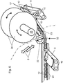
- Fig. 2 the application unit 19 is shown in a plan view.
- the upper system drum 3.1 connects.
- An arrow is shown on the suction head 13 (see also Fig. 1 ) to show the movements during sheet separation.
- the system drum 3.1 here largely covers the feed table 2, so that this as in Fig. 1 is highlighted in dashed lines.
- two arc-shaped arrows are shown transversely to the gripper system 8 and a longitudinal arrow is shown parallel to its extension.
- the printed sheet B can be aligned both transversely to the conveying direction R, ie with regard to its side edges, and with regard to a pivoting of its front edge to the conveying direction by means of the gripper system 8.2.
- the sheet alignment can take place during the sheet transport between the system drum 3.1 to the system drum 3.2, in the course of the sheet transfer to the system drum 3.1 or in the course of the sheet transfer from the system drum 3.2 to the impression cylinder 5.
- FIGs 3 and 4 Possibilities for sheet alignment in connection with gripper systems 8 are shown.
- the gripper systems 8 are assigned guide rails 12 here (see also Fig. 2 ), the gripper systems 8 being moved on conveyor chains 23 by means of guide rollers 10 in the guide rails 12.
- FIG. 3 an alignment element 15 is shown, which moves from a drum-mounted and axially to a stop point that can be positioned on an upper or lower contact drum 3.1, 3.2 when the gripper system 8 enters an alignment opening there 16 intervenes.
- the gripper system 8 is guided between the guide rollers 10 and the guide surfaces in the guide opening 16 in a preselected lateral position before and while a printed sheet B is picked up by the grippers 9 on the gripper system 8 and fixed or transferred in a fixed position to an impression cylinder 5 .
- the printed sheet B can be aligned axially on contact drums 3.1 or 3.2, ie in the direction of the side edges of the sheet transversely to the conveying direction R.
- a circumferential or inclined alignment of the printed sheet B in the direction of the sheet leading edge is carried out.
- the catch forks 17 engage in the guide pins 18 on the gripper systems 8 from holding points that are fixed to the drum and are adjustable in relation to the circumference of a contact drum 3.1 or 3.2.
- the gripper system is thus positioned in the conveying direction R so that the printed sheet B held in the grippers is also positioned.
- the alignment element 15 and the catch forks 17 can be positioned during the sheet travel to ensure an exact sheet transfer for the best possible production accuracy.
- Fig. 5 is in a representation according to Fig. 2 a variant according to the invention, each with a single drive motor 30, 31, which each access one of the conveyor chains 23 and thus drive them independently of one another.
- the orientation of the gripper systems 8 linked to the conveyor chains 23 can thus be adjusted relative to one another with regard to the position of the suspension points on the conveyor chains 23.
- the positions relative to the impression cylinder 5 can also be set at the transfer position at the lower contact drum 3.2.
- the upper transfer position after the upper system drum 3.1 in the transfer section Ü is also controllable.
- the suction head 13 be set even by means of a self-propelled 26 to a transfer position after the upper drum 3.1.
- Fig. 6 are shown in accordance with Figures 3 and 4 presented in combination two further approaches.
- a recess 32 is provided in the guide tracks 12.
- the tensioning rollers 33 are moved in the direction of an adjusting movement S against the conveyor chains 22, 23.
- a movement in the direction of the outside of the deflection causes the conveyor chains 22, 23 to be shortened with the corresponding side of the gripper systems 8 being withdrawn.
- the retraction of the tensioning roller 33 causes the conveyor chains 22, 23 to be released and the gripper systems 8 to be advanced.
- one of the system drums 3.1, 3.2 is provided at the end of the conveyor system 11 in the area of the deflection of the conveyor chains 22, 23, one of the system drums 3.1, 3.2 is provided.
- This is in Fig. 6 shown only on the basis of two guide disks 34, possibly designed as chain wheels or assigned to chain wheels of the drum.
- the guide disks 34 are therefore part of the contact drum 3.1 or 3.2 and carry fishing forks on the outer circumference (see Fig. 4 ).
- the guide disks 34 are adjustably mounted on a shaft 35 of the contact drum 3.1 or 3.2, so that the catch forks 17 can be adjusted in the circumferential direction of the contact drum 3.1 or 3.2 together or with respect to one another.
- the means shown are based on the two solutions Fig. 6 In turn, a shift and adjustment of the movement of the gripper systems 8 in the running direction or in the sense of an inclined position with a corresponding correction of the arc movement is possible.
- Fig. 7 corresponds to a representation for describing a first independently operable drive configuration Fig. 1 elected.
- the drive of the conveyor system 11 in the feed unit 19 takes place via at least one independently operated first drive motor 25 on the axis of the lower feed drum 3.2 in synchronization of the movement of the printed sheets B with the movement of the sheet-fed offset printing machine.
- the sheet separation takes place via an independently operated second drive motor 26 in connection with the suction head 13 in the sheet feeder 1.
- the conveyor chains 23 and the chain wheels of the upper system drum 3.1 are thus set in transport motion by the first drive motor 25 via the chain wheels of the lower system drum 3.2. If both sprockets of the lower system drum 3.2 are coupled to a rigid axle, the position of the leading edge of the printed sheet B can be adjusted relative to the movement of the sheet-fed offset printing machine via the driven gripper systems 8 by the drive movement of the first drive motor 25. In this way, a precisely fitting sheet transfer from the gripper systems 8 on the contact drum 3.2 to the impression cylinder 5 in relation to the machine cycle of the sheet-fed offset printing press can take place in a simple manner.
- each of the chain wheels of the lower system drum 3.2 is provided with its own first drive motor 25, the printed sheet B can be aligned via the gripper systems 8 both with regard to the position of the sheet leading edge in the transport direction and with regard to a possible inclined position of the sheet leading edge by means of an independently controlled drive movement.
- the signals for controlling the first and second drive motors 25, 26 with regard to the sheet position are obtained by sheet position sensors 20 in the area of the feed table 2 and the sheet guiding device 21 in the sheet movement on the gripper systems 8 and fed to a controller 24 via data lines 27.
- the position data of the printed sheets B are then processed in the controller 24 together with signals relating to the machine cycle, which are fed to the controller 24 via a machine data line 29 from a machine controller of the sheet-fed offset printing machine.
- a target / actual comparison is made made, which the measured values are compared with the position data of an expected sheet position given by the machine control. Deviations obtained therefrom are processed into control signals which are passed via control lines 28 to the first and second drive motors 25, 26 in order to control the sheet conveying for correcting incorrect positions of the printed sheet B via their drive movement.
Description
Die Erfindung betrifft eine Anlegeeinheit für eine Bogendruckmaschine nach dem Oberbegriff von Anspruch 1.The invention relates to a feed unit for a sheet-fed printing machine according to the preamble of
Anlegeeinheiten zum Vereinzeln und gezielt taktmäßigen Zuführen von Bogen zu einem Arbeitsprozess sind im Zusammenhang mit Bogenrotationsdruckmaschinen bekannt. Die Bogenförderung erfolgt über Gegendruckzylinder und Transfertrommeln. Der Druckprozess arbeitet z.B. nach dem Flexo- oder Offsetdruckverfahren. Bekannt sind auch Bogenbeschichtungsmaschinen wie etwa Lackiermaschinen. An bekannten Bogendruckmaschinen wird das Anlegen und Ausrichten des Bedruckstoffes in Einrichtungen zur Bogenanlage vorgenommen, der von einem Bogenstapel vereinzelte Bogen als Schuppenstrom über einen Bändertisch zugeführt werden. Der Schuppenstrom der Druckbogen kann mittels Saugbändern über einen Saugbändertisch gefördert werden. Eine Bogenanlage weist dabei üblicherweise Seitenmarken auf, die mit pneumatischen Fördermitteln arbeiten können, und es sind Vorder- und Deckmarken vorgesehen. Schließlich sind diese Ausrichtmittel meist mit einer Formatverstellung versehen. Die Bogenanlage enthält auch sensorische Einrichtungen zur Kontrolle der Lage von Vorderkanten, Seitenkanten, eine Schräglage oder Mehrfachlage der Druckbogen. Mit sensorischen Einrichtungen wirken Anlagesperren zusammen, die Druckbogen bei Lageungenauigkeit im Bogentransport blockieren. Der Bogenanlage nachgeordnet sind oszillierende Vorgreifer, die mit rotierenden Übergabetrommeln zusammenwirken. Der Bedruckstoff wird auf seinem Förderweg abrupten Richtungswechseln unterworfen und erfährt starke Verzögerungen sowie Beschleunigungen.Feeding units for separating and deliberately feeding sheets into a work process are known in connection with sheet-fed rotary printing machines. The sheets are conveyed via impression cylinders and transfer drums. The printing process works e.g. according to the flexographic or offset printing process. Sheet coating machines such as varnishing machines are also known. In known sheet-fed printing machines, the application and alignment of the printing material is carried out in devices for the sheet-fed system, to which sheets separated from a pile of sheets are fed as an imbricated stream via a belt table. The imbricated flow of printed sheets can be conveyed over a suction belt table by means of suction belts. A sheet system usually has side marks that can work with pneumatic conveying means, and front and top marks are provided. Finally, these alignment means are usually provided with a format adjustment. The sheet system also contains sensory devices for checking the position of front edges, side edges, an inclined position or multiple positions of the printed sheets. System locks work together with sensory devices, which block printed sheets in the event of inaccuracies in the sheet transport. Downstream of the sheet feeder are oscillating pre-grippers that work together with rotating transfer drums. The substrate is subjected to abrupt changes of direction on its conveying path and experiences significant decelerations and accelerations.
Aus
In Bogenanlagen sind auch rotierende Vorgreifer wie in
Aus der
Aus der
Aus
Bekannte Teillösungen zur getakteten Bogenzufuhr zu Bogendruckmaschinen sind meist veraltet und werden steigenden Anforderungen an Qualität, Leistung, Kosten und Verfügbarkeit nicht gerecht. Besonders erwünscht ist, dass Druckbogen nicht mehrfachen Beschleunigungs- und Verzögerungsvorgängen sowie zusätzlich erforderlichen Richtungswechseln im Bedruckstofftransport ausgesetzt sind. Der für den Transport jedes Druckbogens bestimmende an den Arbeitstakt der Bogendruckmaschine angepasste Greiferschluss zur Erfassung der Bogenvorderkante sollte so weit wie möglich in der Nähe des Bogenanlegers hergestellt werden können. Der häufig fehlerbehaftete oder als besonders fehleranfällig bekannte geschuppte Bogentransport sollte, wenn irgend möglich entfallen.Known partial solutions for synchronized sheet feeding to sheet-fed printing machines are mostly out of date and do not meet the increasing demands on quality, performance, costs and availability. It is particularly desirable that printed sheets are not subjected to multiple acceleration and deceleration processes as well as additionally required changes of direction in the substrate transport. It should be possible to produce the gripper closure for capturing the leading edge of the sheet, which determines the transport of each printed sheet and is adapted to the work cycle of the sheet-fed printing machine, in the vicinity of the sheet feeder. The shingled sheet transport, which is often error-prone or is known to be particularly error-prone, should be omitted if at all possible.
Der Aufwand zur Luftversorgung an Saugbändertischen für Lüfter, eine Mehrkammerausführung und eine Schrägbogenkorrektur über Saugbänder soll entfallen. Die Ausrichtung der Druckbogen soll in der Förderbewegung während des Transportes vom der Bogenvereinzelung im Bogenanleger dienenden Saugkopf bis zu einem Gegendruckzylinder im ersten Druckwerk der Bogendruckmaschine erfolgen. Damit stünde erheblich mehr Zeit zum Ausrichten der Druckbogen vor dem ersten Druckwerk der Bogendruckmaschine zur Verfügung.The effort for air supply to suction belt tables for fans, a multi-chamber design and a diagonal curve correction via suction belts should be omitted. The alignment of the printed sheets is to take place in the conveying movement during transport from the suction head, which serves to separate the sheets in the sheet feeder, to an impression cylinder in the first printing unit of the sheet-fed printing machine. This would mean considerably more time for aligning the printed sheets in front of the first printing unit of the sheet-fed printing press.
Der Erfindung liegt die Aufgabe zugrunde, eine Anlegeeinheit für eine Bogenverarbeitungsmaschine der eingangs beschriebenen Art zu schaffen, die die genannten Nachteile vermeidet, die insbesondere einen einfachen modularen Aufbau gestattet und eine verbesserte Bogenführung der Druckbogen bei verlängerter Ausrichtzeit erlaubt.The invention is based on the object of creating a feed unit for a sheet processing machine of the type described at the beginning, which avoids the disadvantages mentioned, which in particular allows a simple modular structure and allows improved sheet guidance of the printed sheets with a longer alignment time.
Erfindungsgemäß wird die Aufgabe mit den Merkmalen von Anspruch 1 gelöst. Vorteilhafte Weiterbildungen ergeben sich aus den Unteransprüchen.According to the invention, the object is achieved with the features of
Die Erfindung steht im Zusammenhang mit einer Anlegeeinheit für eine Bogenrotationsdruckmaschine mit einem oder mehreren Druckwerken und/oder Lackmodulen, die mit einem Unterbau aus jeweils doppelt großen Transfertrommeln und Gegendruckzylindern ausgestattet sind. Die Anlegeeinheit ist mit einem Bogenanleger, einer Fördereinheit und einem Zuführtisch versehen, wobei diese eine einfach- oder doppeltgroße Anlagetrommel aufweisen kann, die einer bogenführenden Trommel eines ersten Druckwerkes der Bogenrotationsdruckmaschine zugeordnet ist. Erfindungsgemäß ist die Fördereinheit als ein die untere Anlagetrommel mit einer oberen Anlagetrommel verbindendes endloses Fördersystem ausgebildet, wobei die obere Anlagetrommel dem Bogenanleger zugeordnet ist. Es sind Mittel zur relativ zu der oberen und/oder unteren Anlagetrommel umfangsbezogenen Verstellung des endlosen Fördersystems vorgesehen.The invention relates to a feed unit for a sheet-fed rotary printing press with one or more printing units and / or coating modules, which are equipped with a substructure of double-sized transfer drums and impression cylinders. The feed unit is provided with a sheet feeder, a conveyor unit and a feed table, which can have a single or double-sized feed drum which is assigned to a sheet-guiding drum of a first printing unit of the sheet-fed rotary printing press. According to the invention, the conveyor unit is designed as an endless conveyor system that connects the lower system drum to an upper system drum, the upper system drum being assigned to the sheet feeder. Means are provided for the circumferential adjustment of the endless conveyor system in relation to the upper and / or lower system drum.
Vorteilhaft kann vorgesehen sein, dass die obere Anlagetrommel einem Zuführtisch zugeordnet ist und dass der Zuführtisch dem Bogenanleger zugeordnet ist, wobei die Bogenübernahme an der oberen Anlagetrommel auf unterschiedliche Positionen der Druckbogen in deren Förderrichtung einstellbar ist.It can advantageously be provided that the upper feeder drum is assigned to a feed table and that the feeder table is assigned to the sheet feeder, the sheet transfer on the upper feeder drum being adjustable to different positions of the printed sheets in their conveying direction.
Vorteilhaft kann vorgesehen sein, dass die untere Anlagetrommel einem Gegendruckzylinder des ersten Druckwerkes der Bogenrotationsdruckmaschine zugeordnet ist und dass die Bogenübergabe von der unteren Anlagetrommel auf den Gegendruckzylinder auf unterschiedliche Positionen der Druckbogen in deren Förderrichtung einstellbar ist.It can advantageously be provided that the lower contact drum is assigned to an impression cylinder of the first printing unit of the sheet-fed rotary printing press and that the sheet is transferred from the lower contact drum to the impression cylinder can be adjusted to different positions of the printed sheets in their conveying direction.
Erfindungsgemäß ist das Fördersystem als endloser Kettenförderer mit mehreren Greifersystemen ausgebildet, wobei die Greifersysteme sich zwischen zwei in parallel zueinander verlaufenden Führungsschienen laufenden Förderketten erstrecken. Die Führungsschienen bilden eine geschlossene Führungsbahn unter Einschluss der unteren Anlagetrommel und der oberen Anlagetrommel. Im Bereich des in Förderrichtung verlaufenden Teils des Fördersystems sind Mittel zur Verlagerung der Greifersysteme an den Förderketten in oder entgegen der Förderrichtung vorgesehen.According to the invention, the conveyor system is designed as an endless chain conveyor with several gripper systems, the gripper systems extending between two conveyor chains running in parallel guide rails. The guide rails form a closed guideway including the lower system drum and the upper system drum. In the area of the part of the conveyor system running in the conveying direction, means are provided for moving the gripper systems on the conveyor chains in or against the conveying direction.
Vorteilhaft kann vorgesehen sein, dass in Verbindung mit der oberen Anlagetrommel und/oder der unteren Anlagetrommel Einrichtungen zur verstellbaren Aufnahme von in die Greifersysteme eingreifenden Fanggabeln vorgesehen sind. Vorteilhaft kann vorgesehen sein, dass im Bereich der oberen Anlagetrommel und/oder der unteren Anlagetrommel Einrichtungen zur verstellbaren Querverlagerung der Förderketten aus der stetig verlaufenden Führungsbahn innerhalb der Führungsschienen vorgesehen sind.It can advantageously be provided that, in connection with the upper contact drum and / or the lower contact drum, devices are provided for the adjustable reception of catching forks that engage in the gripper systems. Provision can advantageously be made for devices for the adjustable transverse displacement of the conveyor chains from the continuously running guide track within the guide rails to be provided in the area of the upper contact drum and / or the lower contact drum.
Vorteilhaft kann vorgesehen sein, dass in dem Bereich des Fördersystems, der von der oberen Anlagetrommel zu der unteren Anlagetrommel führt, Einrichtungen zum jeweils eigenständigen Antrieb jeder der Förderketten mit den damit verbundenen Greifersystemen innerhalb deren jeweiliger Führungsschienen vorgesehen sind. Die Förderketten werden synchron und gemeinsam gegenüber kooperierenden Einrichtungen vor- oder nacheilend oder asynchron mit kurzeitiger Vor- oder Nacheilung jeweils einer der Förderketten gegenüber der anderen angetrieben. Vorteilhaft kann vorgesehen sein, dass zur Lageerfassung der der Bogenrotationsdruckmaschine zuzuführenden Druckbogen an der oberen und/oder an der unteren Anlagetrommel und/oder an dem Fördersystem ein oder mehrere Messsysteme mit Bogenlagesensoren benachbart zugeordnet sind. Die Messsysteme sind mit einer Auswerteeinheit und einer Steuerung gekoppelt. Die Steuerung steht mit einer auf das Fördersystem wirkenden Betätigungseinrichtung zur Lagekorrektur von Greifersystemen in Funktionsverbindung.It can advantageously be provided that in the area of the conveyor system which leads from the upper system drum to the lower system drum, devices for the independent drive of each of the conveyor chains with the associated gripper systems are provided within their respective guide rails. The conveyor chains are driven synchronously and jointly, leading or lagging or asynchronously with a short lead or lag of one of the conveyor chains in relation to the other. It can advantageously be provided that, in order to detect the position of the printed sheets to be fed to the sheet-fed rotary printing press, on the upper and / or on the lower Plant drum and / or one or more measuring systems with sheet position sensors are assigned adjacent to the conveyor system. The measuring systems are coupled with an evaluation unit and a controller. The control is functionally connected to an actuating device acting on the conveyor system for correcting the position of gripper systems.
Vorteilhaft kann vorgesehen sein, dass das Fördersystem und/oder ein Saugkopf des Bogenanlegers mit je einem eigenständigen motorischen Antrieb versehen sind. Die motorischen Antriebe sind mittels der Steuerung so mit der Maschinensteuerung der Bogenrotationsdruckmaschine gekoppelt, dass die von dem Fördersystem transportierten Druckbogen in ihrer Lage in Förderrichtung in Bezug auf den Maschinentakt der Bogenrotationsdruckmaschine passgenau zur Drehbewegung der Bogenrotationsdruckmaschine ausrichtbar sind.It can advantageously be provided that the conveyor system and / or a suction head of the sheet feeder are each provided with an independent motor drive. The motor drives are coupled to the machine control of the sheet-fed rotary printing machine by means of the controller in such a way that the position of the printed sheets transported by the conveyor system in relation to the machine cycle of the sheet-fed rotary printing machine can be precisely aligned with the rotary movement of the sheet-fed rotary printing machine.
Vorteilhaft kann vorgesehen sein, dass die obere und/oder die untere Anlagetrommel mit einem oder zwei eigenständigen motorischen Antrieben versehen sind. Der oder die motorischen Antriebe sind mittels der Steuerung mit der Maschinensteuerung der Bogenrotationsdruckmaschine gekoppelt.It can advantageously be provided that the upper and / or the lower contact drum are provided with one or two independent motor drives. The motor drive or drives are coupled to the machine control of the sheet-fed rotary printing press by means of the controller.
Vorteilhaft kann vorgesehen sein, dass eine oder beide Förderketten des Fördersystems mit je einem eigenständigen motorischen Antrieb versehen sind. Die motorischen Antriebe sind mittels der Steuerung mit der Maschinensteuerung der Bogenrotationsdruckmaschine gekoppelt.It can advantageously be provided that one or both conveyor chains of the conveyor system are each provided with an independent motor drive. The motor drives are coupled to the machine control of the sheet-fed rotary printing press by means of the controller.
Von Vorteil ist ebenso, dass die Maschinengeschwindigkeit erhöht werden kann bar ist, da die Anlagetrommel stets in Förderrichtung rotierend ausgebildet sind und die bei herkömmlichen Schwingsystemen erforderliche Zeit für das Zurückschwingen nicht benötigt wird. Hierbei treten auch keine Flankenwechsel an den Antriebssystemen auf, was den ruhigen Lauf der Maschine unterstützt. Rückwirkende Momente auf den Antriebsräderzug sind spürbar verringert und der Antrieb selbst ist einfacher ausgebildet.It is also advantageous that the machine speed can be increased because the system drums are always designed to rotate in the conveying direction and the time required for swinging back in conventional oscillation systems is not required. There are also no edge changes on the drive systems, which supports the smooth running of the machine. Retroactive moments on the drive train are noticeably reduced and the drive itself is designed to be simpler.
Ein weiterer Vorteil ist in der Verbesserung der Bogenführung begründet. Durch die geneigte oder bevorzugt horizontale Ausbildung des Zuführtisches in Verbindung mit der zum Zuführtisch angeordneten Anlagetrommel wird durch den relativ großen Trommeldurchmesser der Druckbogen weniger gekrümmt als beispielsweise bei einer einfachgroßen Anlagetrommel. Die Anlegeeinheit ist damit universell für die Verarbeitung von relativ dünnen Druckbogen als auch von dicken Druckbogen, wie z.B. Karton oder Blech, unabhängig vom Elastizitätsverhalten der Druckbogen einsetzbar.Another advantage is the improvement of the sheet guidance. Due to the inclined or preferably horizontal design of the feed table in connection with the feeder drum arranged to the feed table, the printed sheet is less curved than, for example, with a single-sized feeder drum due to the relatively large drum diameter. The feed unit can therefore be used universally for processing relatively thin printed sheets as well as thick printed sheets, such as cardboard or sheet metal, regardless of the elasticity of the printed sheet.
Die Anordnung der oberen Anlagetrommel auf einer oder höhenversetzt oberhalb einer durch die Achsen aller Gegendruckzylinder gebildeten horizontalen Ebene gestattet bei einem horizontal angeordnetem Zuführtisch in Höhe der Stapeloberfläche die Ausbildung eines Hochstapelanlegers. Ein aufwendiger Austausch eines Normalstapelanlegers gegen einen Hochstapelanleger ist hinfällig.The arrangement of the upper feed drum on one or vertically offset above a horizontal plane formed by the axes of all impression cylinders allows the formation of a high pile feeder with a horizontally arranged feed table at the height of the stack surface. A costly exchange of a normal pile feeder for a high pile feeder is no longer necessary.
Vorteilhaft ist ebenso, dass bei einem horizontal angeordneten Zuführtisch der vom Bogenanleger vereinzelte Bogen direkt in einer horizontalen Förderebene der oberen Anlagetrommel zugeführt werden und in deren Greifersystemen an dort integrierten Vordermarken angelegt werden kann. Damit sind mögliche Beschädigungen am Druckbogen vermeidbar, welche beispielsweise am Übergang vom Bogenanleger zum Zuführtisch auftreten können.It is also advantageous that, with a horizontally arranged feed table, the sheets separated by the sheet feeder are fed directly to the upper feed drum in a horizontal conveying plane and can be applied to the front lays integrated there in its gripper systems. In this way, possible damage to the printed sheet can be avoided, which can occur, for example, at the transition from the sheet feeder to the feed table.
Der Zuführtisch ist bevorzugt ebene Fläche ausgebildet und mit Längsöffnungen versehen, in die die beim Einlauf an der oberen Anlagetrommel geöffneten Greiferfinger der Greifersysteme des Fördersystems eintauchen. Bei horizontaler Anordnung des Fördertisches ist von Vorteil, dass die vom Bogenstapel angeförderten vereinzelten Druckbogen auf stark verkürzter Förderstrecke zu ihren Ausrichtmarken gelangen und sofort auf volle Geschwindigkeit beschleunig werden können. Somit ist kann die Länge des Zuführtisches verkürzt werden und bei beispielsweise einem Stopper fällt weniger Makulatur an.The feed table is preferably designed as a flat surface and provided with longitudinal openings into which the gripper fingers that are opened when entering the upper contact drum the gripper systems of the conveyor system. When the conveyor table is arranged horizontally, it is advantageous that the individual printed sheets conveyed by the stack of sheets arrive at their alignment marks on a greatly shortened conveyor path and can be accelerated to full speed immediately. This means that the length of the feed table can be shortened and with a stopper, for example, there is less waste.
Die konstruktive Ausführung der erfindungsgemäßen Lösung weist eine Parallelführung auf dem Anlageblech zwischen den Greifersystemen und dem vom Saugkopf angeschobenen Druckbogen als Anlagebereich entsprechend einem herkömmlichen Anlageblech im Bogenanleger auf.The structural design of the solution according to the invention has a parallel guide on the contact plate between the gripper systems and the printed sheet pushed by the suction head as a contact area corresponding to a conventional contact plate in the sheet feeder.
Die Druckbogen können mittels einer Anlagesperre im Bogenanleger zurückgehalten werden. Hierdurch fällt weniger bis keine Makulatur durch Druckbogen an, die nach bekannter Art bei Stoppern auf dem Bändertisch liegen bleiben und abgeräumt werden müssen wodurch sie unbrauchbar werden.The printed sheets can be held back in the sheet feeder by means of a system lock. As a result, there is less or no waste due to printed sheets, which, in the known manner, remain on the conveyor table with stoppers and have to be cleared away, making them unusable.
Die Ausrichtung des Druckbogens kann während des Transportes zwischen dem Anlegerstapel und dem ersten Druckwerk erfolgen. Axial, d.h. quer zur Papierlaufrichtung wird der so genannte Seitenpasser durch Seitenausrichtung eingestellt. Die Ausrichtung hinsichtlich von Schrägbogen und der Lage der Vorderkante wird über die Vorwärtsbewegung der Greifersysteme gesteuert.The alignment of the printed sheet can take place during transport between the feeder stack and the first printing unit. The so-called page register is set axially, i.e. transversely to the direction of paper travel, by aligning the page. The alignment with regard to oblique sheets and the position of the leading edge is controlled by the forward movement of the gripper systems.
Eine Sensorik mit Bogenkontrollsensoren im Verlauf des Fördersystems ist mit einem geschlossenen Regelkreis verbunden und sorgt dafür, dass Früh-, Spät-, Doppel- und Schrägbogen schon auf dem Anlageblech erkannt werden und so von der Übernahme in den Bogentransport mittels des Fördersystems ausgeschlossen werden.A sensor system with sheet control sensors in the course of the conveyor system is connected to a closed control loop and ensures that early, late, double and inclined sheets are recognized on the contact plate and are thus excluded from being transferred to the sheet transport by the conveyor system.
Möglich ist auch ein Einzelantrieb des Bogenanlegers, so dass dann ein Inline-Ausrichtung der Früh-/Spätbogen entfallen könnte, da die Vorwärtsbewegung der vereinzelten Druckbogen mittels des Einzelantriebs beeinflusst werden kann.An individual drive of the sheet feeder is also possible, so that an inline alignment of the early / late sheets could then be dispensed with, since the forward movement of the separated printed sheets can be influenced by means of the individual drive.
Die bisher in der Anlagetechnik benutzten Ausrichttechniken in Papierlaufrichtung sind vorrangig einstellbare Vordermarken und zur Verhinderung von Bogenüberschießern werden Deckmarken verwendet. Diese machen einen großen mechanischen Steueraufwand nötig und können, aufgrund der Schwenkbewegungen, Kratzer am einlaufenden Bogen verursachen. Feststehende Marken markieren darüber hinaus die Bogenvorderkante und machen eine Verlangsamung des Bedruckstoffes erforderlich, was ein zusätzliches Getriebe erfordert. Der Bogen wird durch die Anschlagskonstruktion angehalten. Bedruckstoffdicken müssen eingestellt werden. Die Bögen müssen durch Saugrollen an der Vordermarke gehalten werden.The alignment techniques in the direction of paper travel that have been used up to now in system technology are primarily adjustable front lays and to prevent sheet overshoot cover marks are used. These require a great deal of mechanical control effort and, due to the pivoting movements, can cause scratches on the incoming sheet. Fixed marks also mark the leading edge of the sheet and make it necessary to slow down the printing material, which requires an additional gear. The bow is stopped by the stop construction. Substrate thicknesses must be set. The sheets must be held on the front lay by suction rollers.
Die o.g. Einrichtungen entfallen komplett. Die Ausrichtung des Bedruckstoffes wird im Förderprozess beim Transport vom Saugkopf zum Gegendruckzylinder ausgeführt. Beim ruhenden, in der Vorderkante ausgerichteten Bogen wie derzeit serienmäßig ausgeführt, wird der Bogen anschließend seitlich an einen Anschlag gezogen. Es besteht die Gefahr des Verrutschens. Es treten Stopper und somit Makulatur auf, die durch die Erfindung minimiert wird. In manchen Fällen kann die Anlage nicht mehr rechtzeitig gesperrt werden und der Bogen läuft ein. Hier kann es bis zum Maschinenbruch und Zerstörung der Gummitücher etc. kommen. Dies wird durch die Erfindung vermieden.The above-mentioned facilities are completely omitted. The alignment of the printing material is carried out in the conveying process during transport from the suction head to the impression cylinder. When the sheet is stationary and aligned in the leading edge, as is currently standard, the sheet is then pulled sideways against a stop. There is a risk of slipping. There are stoppers and thus waste, which is minimized by the invention. In some cases, the system can no longer be blocked in time and the sheet is fed in. This can lead to machine breakdowns and destruction of the blankets etc. This is avoided by the invention.
Die Bögen werden beim Transport zwischen Saugkopf und dem Gegendruckzylinder des ersten Druckwerks durch eine Verstelleinrichtung ausgerichtet. Diese kann eine Fanggabel im Ausrichtzylinder sein, die das Transportsystem im Umfang ausrichtet und auch Schrägbogen korrigiert. Die Greifersysteme werden durch eine endlose Kette befördert und müssen jedes für sich ausrichtbar gestaltet werden. Dies ist axial durch schwimmende Aufhängung möglich, eine Schrägbogenausrichtung oder eine Ausrichtung im Umfang macht jedoch eine Entkoppelung des Transportsystems von den Antriebsketten notwendig. Ausführungsvariante 1: Die Kette wird nicht, wie üblich, durch ein Kettenrad auf der Zylinderachse angetrieben, sondern durch zwei separate Kettenantriebe je auf einer Seite. Die Grundaufgabe dieser Antriebe ist die Beförderung der Transportsysteme und des Bedruckstoffes. Durch Beschleunigen oder Verlangsamen beider Antriebe kann die Vorderkante früher oder später an den Druckzylinder übergeben werden. Bei der Beschleunigung oder der Verlangsamung auf nur einer Seite können Schrägbogen korrigiert werden.The sheets are aligned during transport between the suction head and the impression cylinder of the first printing unit by an adjustment device. This can be a catch fork in the alignment cylinder, which aligns the transport system in terms of its circumference and also corrects oblique bends. The gripper systems are conveyed through an endless chain and each must be designed so that it can be aligned. This is possible axially by means of a floating suspension, but an inclined curve alignment or an alignment in the circumference makes it necessary to decouple the transport system from the drive chains. Design variant 1: The chain is not driven, as usual, by a chain wheel on the cylinder axis, but by two separate chain drives on each side. The basic task of these drives is to move the transport systems and the printing material. By speeding up or slowing down both Drives, the leading edge can be transferred to the printing cylinder sooner or later. When accelerating or decelerating on one side only, skew can be corrected.
Ausführungsvariante 2: Die Systeme werden durch Fangabeln, die beidseitig gleich verstellbar den Bedruckstoff in Papierlaufrichtung und einseitig verstellbar Schrägbogen ausrichten bzw. korrigieren. Der Kettenstrang ist geschlossen. Damit die Übernahme des Bogens, die Ausrichtung und die Übergabe sich nicht gegenseitig beeinflussen, muss die Länge der Kette von einem zum anderen Transportsystem variabel sein. Dies wird durch eine Anfederung gelöst, die unterschiedliche Abstände der Greifersysteme zulässt, die dann vor jeder Ausrichtstation angesteuert werden können. Das System wird in der oberen Anlagetrommel immer vorausgerichtet. Die dazu notwendigen Stellglieder können elektrisch, pneumatisch oder hydraulisch usw. ausgeführt werden. Eine Vorausrichtung des Transportsystems kann schon im Hinblick auf den Bogen, der noch auf dem Stapel liegt, stattfinden, die Systeme werden voreingestellt und übernehmen den Bedruckstoff, schon in einer (vor-) korrigierten Stellung, in der oberen Anlagetrommel. Bei Bedruckstoffen die schon außerhalb eines Korrekturkorridors liegen, kann hier beliebig die Anlage gesperrt werden. Die auf das Bedruckstoffformat manuell oder automatisch verstellbaren Bogenlagesensoren erfassen die Vorderkante des Bedruckstoffes nach Übernahme in das Transportsystem auf dem Anlageblech. Die Stellglieder (Motoren, Fanggabeln) richten den Bogen auf dem Weg zur unteren Anlagetrommel oder in der Anlagetrommel aus. Die sehr kurze Zeit bekannter Vordermarkenausrichtungen wird durch diese Lösung erheblich verlängert. Damit nach der Ausrichtung das Transportsystem nicht mehr verstellt wird, ist eine Befestigung (Klemmung)vorgesehen.Design variant 2: The systems are aligned or corrected by means of catch forks, which can be adjusted equally on both sides in the direction of the paper flow and the oblique sheets can be adjusted on one side. The chain strand is closed. So that the takeover of the sheet, the alignment and the transfer do not influence each other, the length of the chain must be variable from one transport system to the other. This is solved by a spring system that allows different distances between the gripper systems, which can then be controlled in front of each alignment station. The system is always pre-aligned in the upper system drum. The actuators required for this can be designed electrically, pneumatically or hydraulically, etc. A pre-alignment of the transport system can take place with regard to the sheet that is still on the stack, the systems are pre-set and take over the printing material, already in a (pre-) corrected position, in the upper feed drum. In the case of substrates that are already outside a correction corridor, the system can be blocked here as required. The sheet position sensors, which can be manually or automatically adjusted to the printing material format, detect the leading edge of the printing material on the contact plate after it has been transferred to the transport system. The actuators (motors, fishing forks) align the sheet on the way to the lower system drum or in the system drum. The very short time known front lay alignments is considerably extended by this solution. A fastening (clamp) is provided so that the transport system is no longer adjusted after alignment.
Weiterhin sind auch eine Ausschleusung von Schlechtbogen während des Transportes sowie eine Auto-Non-Stop-Bogenzuführung denkbar.Furthermore, a discharge of bad sheets during transport and an auto-non-stop sheet feed are also conceivable.
Die Erfindung wird an einem Ausführungsbeispiel näher erläutert. Dabei zeigen:
- Fig. 1
- ein Bogenanleger mit einer Bogenzufuhreinheit für eine Bogendruckmaschine im seitlichen Aufriss,
- Fig. 2
- eine Anlegeeinheit nach
Fig. 1 in der Draufsicht, - Fig. 3
- eine Anlegeeinheit in Funktionsverbindung mit einem Führungselement zur seitlichen Ausrichtung,
- Fig. 4
- eine Anlegeeinheit in Funktionsverbindung mit zwei Führungselementen zur umfangsbezogenen Ausrichtung,
- Fig. 5
- eine Anlegeeinheit nach
Fig. 4 mit einer Umfangsausrichtung, - Fig. 6
- eine Anlegeeinheit mit einer weiteren umfangsbezogenen Ausrichtung und
- Fig. 7
- eine Anlegeeinheit mit einer motorisch betriebenen umfangsbezogenen Ausrichtung.
- Fig. 1
- a sheet feeder with a sheet feed unit for a sheet-fed printing machine in side elevation,
- Fig. 2
- an application unit after
Fig. 1 in plan view, - Fig. 3
- a positioning unit in functional connection with a guide element for lateral alignment,
- Fig. 4
- a positioning unit in functional connection with two guide elements for circumferential alignment,
- Fig. 5
- an application unit after
Fig. 4 with a circumferential orientation, - Fig. 6
- an application unit with a further circumferential orientation and
- Fig. 7
- a placement unit with a motorized circumferential alignment.
Eine Bogenrotationsdruckmaschine (Offsetdruckmaschine) gemäß
In jedem Druckwerk D1, D2 sind ausgehend von einfachgroßen Drucktuch- 7 und Formzylinder 6 die Gegendruckzylinder 5 und Transfertrommeln 4 doppeltgroß ausgebildet und weisen je zwei Greiferreihen 22 für den Bogentransport auf. Die Anlegeeinheit 19 besteht aus einem Bogenanleger 1, einem Zuführtisch 2 und einfach oder doppeltgroß ausgebildeten oberen und unteren Anlagetrommeln 3.1, 3.2. Die obere Anlagetrommel 3.1 und die untere Anlagetrommel 3.2 sind durch ein zwei endlose Förderketten 23 aufweisendes Fördersystem 11 miteinander verbunden. Das Fördersystem 11 weist im Ausführungsbeispiel fünf an den Förderketten in Führungsschienen 12 umlaufende Greifersysteme 8 auf. Die Greifersysteme 8 sind balkenförmig sich quer zur Förderrichtung R zwischen den Förderketten 23 erstreckende Balkenelemente ausgebildet, welche eine Reihe von Greifern 9 zum Transport von Druckbogen B an deren Bogenvorderkante aufweisen.In each printing unit D1, D2, starting from the single-
Der Zuführtisch 2 ist direkt im Anschluss an eine in Förderrichtung R gelegene Oberkante eines im Bogenanleger 1 vorgehaltenen Bogenstapels 14 angeordnet und im Wesentlichen horizontal ausgerichtet. Dem Zuführtisch 2 ist der Oberfläche des Bogenstapels 14 zugeordnet ein Saugkopf 13 vorgeordnet, mittels dessen der jeweils oberste Bogen vom Bogenstapel 14 getrennt und mittels Saugern 13.1 in Richtung zum Zuführtisch 2 vorgeschoben wird bis er eine Übernahmestrecke Ü zum Ergreifen der Bogenvorderkante durch die Greifersysteme 8 erreicht.The feed table 2 is arranged directly following an upper edge, located in the conveying direction R, of a
Oberhalb des Zuführtisches 2 ist die obere Anlagetrommel 3.1 angeordnet. Über die Anlagetrommel 3.1 werden die an endlosen Förderketten 23 geführten Greifersysteme 8 durch das Fördersystem 11 auf Führungsschienen 12 in den Bereich der Bogenübergabe parallel zum Zuführtisch 2 über eine Übernahmestrecke Ü geführt. Der vereinzelte Druckbogen B wird also von den Greifersystemen 8 mit nach unten geöffneten Greifern 9 auf dem Zuführtisch 2 übernommen, nachdem die Bogenvorderkante seitens des Saugkopfes 13 in die Greifer 9 eingeführt wurde und indem der Druckbogen B dann an der Bogenvorderkante erfasst wurde. Danach kann er vom Zuführtisch 2 abtransportiert werden.The upper feed drum 3.1 is arranged above the feed table 2. The
Unterhalb des Zuführtisches 2 ist eine Einrichtung mit einem oder mehreren Bogenlagesensoren 20.1 angeordnet. Mittels der Bogenlagesensoren 20 wird die Lage der Bogenvorderkante des gerade vom Bogenstapel 14 vereinzelten und vom Greifersystem 8 mit den Greifern 9 übernommenen Druckbogens B erfasst und hinsichtlich seiner Lage in Bezug auf den Maschinentakt und der Lage hinsichtlich der Ausrichtung beim Transport in Förderrichtung R ausgewertet.A device with one or more sheet position sensors 20.1 is arranged below the feed table 2. By means of the
Unterhalb des Fördersystems 11 ist in etwa parallel zum abwärts führenden Bogentransportweg eine Bogenführungseinrichtung 21 angeordnet. Mittels der Bogenführungseinrichtung 21 wird jeder vereinzelte Druckbogen B von einem Greifersystem 8 von der oberen Anlagetrommel 3.1 zur unteren Anlagetrommel 3.2 geführt, wo er an den Gegendruckzylinder 5 des ersten Druckwerks D1 übergeben wird. Im Bereich der Bogenführungseinrichtung 21 können weitere Bogenlagesensoren 20 angeordnet sein, um die Lage der Bogenkanten im Greifersystem 8 in Förderrichtung R und quer dazu in Richtung der Seitenkanten der Druckbogen B zu überwachen.Below the
Die aus der Vermessung der Lage der Druckbogen B sich ergebenden Daten werden zur Anpassung der Bogenlage in Bezug auf den Verarbeitungstakt und die Seitenausrichtung jedes einzelnen Druckbogens B verwendet.The data resulting from the measurement of the position of the printed sheet B are used to adjust the sheet position in relation to the processing cycle and the page orientation of each individual printed sheet B.
Auf oder unter dem Zuführtisch 2 ist demzufolge in einer Ausführungsform ein Messsystem mit einigen Bogenlagesensoren 20 angeordnet, welches die Ist-Lage einer Vorder- und/oder Seitenkante des Druckbogens B auf dem Zuführtisch 2 feststellt. In einer Steuerung 24 wird hiermit ein Soll-Ist-Vergleich vorgenommen. Mittels Seitenzieheinrichtung und/oder Vorderkantenausrichtung kann der Druckbogen B dann gesteuert in eine Soll-Lage zur Übernahme durch die Greifer 9 an bzw. in Verbindung mit den Greifersystemen 8 ausrichtet werden.Accordingly, in one embodiment, a measuring system with several
In bevorzugter Ausbildung gem.
Die Anlagetrommel 3.1 ist dabei innerhalb der Anlegeeinheit 19 oberhalb des Zuführtisches 2 derart angeordnet, dass die horizontale Förderebene des Zuführtisches 2 tangential zum entsprechenden Greifersystem 9, das über die Anlagetrommel 3.1 einläuft, verläuft. Die Anlagetrommeln 3.1 und 3.2 können, bezogen auf den einfachgroßen Formzylinder 6, entweder einfach- oder doppeltgroß ausgebildet sein. Dies kann abhängig von den Bauraumbedürfnissen und den Ansprüchen an zu verarbeitende Materialien ausgewählt werden.The feed drum 3.1 is arranged within the
Wenigstens die untere Anlagetrommel 3.2 kann als doppelt große Trommel zur gleichzeitigen Aufnahme von zwei Greifersystemen 8 ausgebildet sein. Sie hat dann einen für die Führung von steiferen Bedruckstoffmaterialien günstigen größeren Durchmesser, so dass die zu transportierenden Druckbogen B nicht so stark gebogen und damit leichter an den Gegendruckzylinder 5 des ersten Druckwerkes D1 übergeben werden können.At least the lower contact drum 3.2 can be designed as a double drum for the simultaneous reception of two
Die obere Anlagetrommel 3.1 weist dieses Problem nicht auf, da die Druckbogen B dort immer erst nach Ablauf der Greifersysteme 8 von der Anlagetrommel 3.1 in den Greifern 9 der Greifersysteme 8 aufgenommen werden.The upper system drum 3.1 does not have this problem, since the printed sheets B are always received there by the system drum 3.1 in the
In einer Weiterbildung ist der unteren Anlagetrommel 3.2 und der Bogenführungseinrichtung 21 ein Messsystem mit wenigstens je einem Bogenlagesensor 20, zur Lageerfassung (Istwert) der an Greifersystemen 8 von der oberen Anlagetrommel 3.1 aus über der Bogenführungseinrichtung 21 und an der unteren Anlagetrommel 3.2 geführten Druckbogen B benachbart zugeordnet. Die Lageerfassung kann sich auf Seitenkanten und die Vorderkante des Druckbogens B beziehen. Die Bogenlagesensoren 20 sind mit einer Auswerteeinheit für den Soll-Ist-Vergleich sowie einer Steuerung schaltungstechnisch gekoppelt, derart, dass die Greifersysteme 8 in einer Ausbildung quer zur Förderrichtung R seitlich bewegbar ist.In a further development, the lower feed drum 3.2 and the
In einer weiteren Ausbildung ist die Funktionsverbindung von Bogenlagesensoren 20, Auswerteeinheit und Steuerung derart, dass eine seitliche Bewegung des Greifersystems 8 realisierbar und/oder bei einer Schräglage des Druckbogens B zur Förderrichtung R dessen Lageversatz erkennbar und der Druckbogen B durch das in oder entgegen der Förderrichtung R schräg verstellbare Greifersystem 8 in Sollposition ausrichtbar ist.In a further embodiment, the functional connection of
Die dem Zuführtisch 2 und/oder der Bogenführungseinrichtung 21 und/oder den Anlagetrommel 3.1 und 3.2 zugeordneten Bogenlagesensoren 20 sind gemeinsam oder einzeln einsetzbar.The
Die Anlagetrommel 3.2 ist im Ausführungsbeispiel nach
Die Wirkungsweise der Anlegeeinheit 19 ist wie folgt:
Im Bogenanleger 1 wird ein bogenförmiger Druckbogen B mittels des Saugkopfes 14 von der Oberseite des Bogenstapels 13 im Maschinentakt vereinzelt und kontinuierlich in Förderrichtung R auf Maschinengeschwindigkeit beschleunigt. In der Vorwärtsbewegung wird der Bogen dem Zuführtisch 2 zugeleitet und hierbei vorzugsweise schon hinsichtlich seiner Lage und auf Doppelbogen oder Bogenbeschädigungen hin untersucht.The operation of the
In the
Beim Einlaufen des Bogens auf dem Zuführtisch 2 kann nach bevorzugter messtechnischer Erfassung des Istwertes und eines Soll-Ist-Vergleichs eine Ausrichtung des bogenförmigen Druckbogens B nach einer Seitenkante erfolgen.When the sheet enters the feed table 2, after a preferred metrological recording of the actual value and a target / actual comparison, the sheet-like printed sheet B can be aligned with a side edge.
Direkt anschließend oder in Bewegungsüberlagerung erfolgt der Transport in Förderrichtung R gegen Vordermarken an dem mit geöffneten Greifern 9 vorauslaufenden über Kopf geführten Greifersystem 9. Die Greifer 9 erfassen dann den Druckbogen B, wenn die Vordermarken an der Bogenvorderkante anliegen, und die Greiferfinger 9 wirken, während die Bogenkante an den Vordermarken anliegt, gleichzeitig als so genannte Deckmarken bis der Druckbogen B im Greiferschluss am Greifersystem 8 fixiert ist. Dieser Vorgang mit der Erfassung der Lage der Vorderkante des Druckbogens B erfolgt bei einer Synchronbewegung zwischen Druckbogen B und Greifersystem 8 parallel zueinander an dem Zuführtisch 2 im Bereich der Übernahmestrecke Ü.Immediately afterwards or in a movement overlay, the transport takes place in the conveying direction R against front lays on the
Das von der rotierenden Anlagetrommel 3.1 abgelaufene Greifersystem 8 wird am Fördersystem 11 in Führungsschienen 12 weiterbewegt und zieht den im Greiferschluss fixierten bogenförmigen Druckbogen B vom Zuführtisch 2 ab und transportiert diesen, während die Anlagetrommel 3.1 ständig mit Maschinengeschwindigkeit bewegt wird, in Förderrichtung R über die Bogenführungseinrichtung 21. Die Bogenführungseinrichtung 21 kann als einfache glatte oder konturierte Leitfläche ausgebildet sein, über die der Druckbogen B geschleppt wird. Die Bogenführungseinrichtung 21 kann auch als pneumatisch beaufschlagte Leitfläche ausgebildet sein, über die der Druckbogen B unter Einfluss von Druckluft schwebend oder unter Einfluss von Saugluft bremsend und gestrafft geschleppt wird.The
Im Bereich der Bogenführungseinrichtung 21 kann eine weitere oder erstmalige messtechnische Erfassung der Druckbogen B mit Auswertung der Lage und entsprechender Korrektur auf der Anlagetrommel 3 erfolgen. Anschließend wird der Druckbogen B von der Anlagetrommel 3.2 im Übergabebereich an den zum ersten Druckwerk D1 zählenden Gegendruckzylinder 5 übergeben. Von dem Gegendruckzylinder 5 des ersten Druckwerks D1 wird der Druckbogen B dann nach erstem Bedrucken der Transfertrommel 4 des zweiten Druckwerks D2 und in bekannter Weise an den nachfolgenden Gegendruckzylinder 5 übergeben.In the area of the
Wenn die Anlagetrommel 3.2 als doppeltgroße Trommel ausgeführt ist, kann ihr Trommelkörper von einer Auslegertrommel am Ende der Bogenoffsetdruckmaschine übernommen werden. Am ersten Druckwerk D1 ist schon eine entsprechende Lagerposition für die standardmäßige Anbringung einer Transfertrommel 4 vorgesehen, in die die Auslegertrommel einsetzbar ist. Die Auslegertrommel ist zudem auch für die Aufnahme von endlosen Kettenfördersystemen vorgesehen.If the system drum 3.2 is designed as a double-sized drum, its drum body can be taken over by a cantilever drum at the end of the sheet-fed offset printing machine. A corresponding storage position for the standard attachment of a
In
Oberhalb der oberen Anlagetrommel 3.1 und der unteren Anlagetrommel 3.2 sind Greifersysteme 8.1 und 8.3 dargestellt, die sich leer laufend gegen die Förderrichtung R auf dem Rückweg zum Bogenanleger 1 befindet.Above the upper system drum 3.1 and the lower system drum 3.2 gripper systems 8.1 and 8.3 are shown, which are idle against the conveying direction R on the way back to the
Ausgehend von der oberen Anlagetrommel 3.1 ist in Förderrichtung R ein weiteres Greifersystem 8.2 gezeigt, das nunmehr einen Druckbogen B hält und diesen in Förderrichtung R zur Anlagetrommel 3.2 transportiert.Starting from the upper system drum 3.1, another gripper system 8.2 is shown in the conveying direction R, which now holds a printed sheet B and transports it in the conveying direction R to the system drum 3.2.
In diesem Zusammenhang sind quer zu dem Greifersystem 8 zwei bogenförmige Pfeile und parallel zu seiner Ausdehnung ein längserstreckter Pfeil dargestellt.In this context, two arc-shaped arrows are shown transversely to the
Diese Pfeile deuten an, dass der Druckbogen B mittels des Greifersystems 8.2 sowohl quer zur Förderrichtung R, also in Bezug auf seine Seitenkanten, als auch in Bezug auf eine Verschwenkung seiner Vorderkante zur Förderrichtung ausgerichtet werden kann. Die Bogenausrichtung kann während des Bogentransports zwischen der Anlagetrommel 3.1 zur Anlagetrommel 3.2, im Verlauf der Bogenübernahme auf die Anlagetrommel 3.1 oder im Verlauf der Bogenübergabe von der Anlagetrommel 3.2 auf den Gegendruckzylinder 5 erfolgen.These arrows indicate that the printed sheet B can be aligned both transversely to the conveying direction R, ie with regard to its side edges, and with regard to a pivoting of its front edge to the conveying direction by means of the gripper system 8.2. The sheet alignment can take place during the sheet transport between the system drum 3.1 to the system drum 3.2, in the course of the sheet transfer to the system drum 3.1 or in the course of the sheet transfer from the system drum 3.2 to the
In
In
Zusätzlich zur axialen Ausrichtung kann nach
Abhängig von Messungen der Bogenlage über die Bogenlagesensoren 20 kann die Positionierung des Ausrichtelements 15 und der Fanggabeln 17 während des Bogenlaufs zur Sicherstellung einer exakten Bogenübergabe für die bestmögliche Produktionsgenauigkeit erfolgen.Depending on measurements of the sheet position via the
In
So ist also eine Korrektur von Schrägbogen, sowie von Früh- und Spätbogen innerhalb der Ausrichtstrecke A ohne weiteres möglich ohne dass eine Unterbrechung des Maschinenlaufes notwendig wäre.Correction of oblique bends, as well as early and late bends within the alignment path A, is thus easily possible without the need to interrupt the machine operation.
In
Im Bereich der Umlenkung der Führungsbahn 12 für die Greifersysteme 8 ist eine Ausnehmung 32 in den Führungsbahnen 12 vorgesehen. Im Bereich der Ausnehmung 32 ist an der Innenseite der Förderketten 22, 23 je eine diese stützende Spannrolle 33 vorgesehen. Die Spannrollen 33 werden in Richtung einer Stellbewegung S gegen die Förderketten 22, 23 bewegt. Dabei wird durch eine Bewegung in Richtung der Außenseite der Umlenkung eine Verkürzung der Förderketten 22, 23 mit einem Zurückziehen der entsprechenden Seite der Greifersysteme 8 bewirkt. Das Zurückziehen der Spannrolle 33 bewirkt eine Freigabe der Förderketten 22, 23 und einen Vorschub der Greifersysteme 8.In the area of the deflection of the
Am Ende des Fördersystems 11 im Bereich der Umlenkung der Förderketten 22, 23 ist eine der Anlagetrommeln 3.1, 3.2 vorgesehen. Diese ist in
Mit den gezeigten Mitteln ist auf Basis der beiden Lösungen aus
In
Die Bogenvereinzelung erfolgt über einen eigenständig betriebenen zweiten Antriebsmotor 26 in Verbindung mit dem Saugkopf 13 im Bogenanleger 1.The sheet separation takes place via an independently operated
Damit werden die Förderketten 23 und die Kettenräder der oberen Anlagetrommel 3.1 von dem ersten Antriebsmotor 25 über die Kettenräder der unteren Anlagetrommel 3.2 in Transportbewegung versetzt. Wenn beide Kettenräder der unteren Anlagetrommel 3.2 mit einer starren Achse gekoppelt sind, kann durch die Antriebsbewegung des ersten Antriebsmotors 25 die Lage der Vorderkante der Druckbogen B über die angetriebenen Greifersysteme 8 relativ zur Bewegung der Bogenoffsetdruckmaschine eingestellt werden. Damit kann auf einfache Weise eine passgenaue Bogenübergabe von den Greifersystemen 8 an der Anlagetrommel 3.2 an den Gegendruckzylinder 5 in Relation zum Maschinentakt der Bogenoffsetdruckmaschine erfolgen.The
Wenn jedes der Kettenräder der unteren Anlagetrommel 3.2 mit einem eigenen ersten Antriebsmotor 25 versehen ist, kann mittels einer unabhängig angesteuerten Antriebsbewegung der Druckbogen B über die Greifersysteme 8 sowohl hinsichtlich der Lage der Bogenvorderkante in Transportrichtung als auch hinsichtlich einer eventuellen Schräglage der Bogenvorderkante ausgerichtet werden.If each of the chain wheels of the lower system drum 3.2 is provided with its own
Die Signale zur Ansteuerung der ersten und zweiten Antriebsmotoren 25, 26 hinsichtlich der Bogenlage werden von Bogenlagesensoren 20 im Bereich des Zuführtisches 2 und der Bogenführungseinrichtung 21 in der Bogenbewegung an den Greifersystemen 8 gewonnen und über Datenleitungen 27 einer Steuerung 24 zugeleitet. In der Steuerung 24 werden die Positionsdaten der Druckbogen B dann zusammen mit auf den Maschinentakt bezogenen Signalen verarbeitet, die der Steuerung 24 über eine Maschinendatenleitung 29 von einer Maschinensteuerung der Bogenoffsetdruckmaschine zugeführt werden. Dabei wird ein Soll-Ist-Vergleich vorgenommen, der die Messwerte mit aus der Maschinensteuerung vorgegebenen Positionsdaten einer erwarteten Bogenlage verglichen werden. Daraus erhaltene Abweichungen werden zu Steuersignalen verarbeitet, die über Steuerleitungen 28 an die ersten und zweiten Antriebsmotoren 25, 26 geleitet werden, um über deren Antriebsbewegung die Bogenförderung zur Korrektur von Fehllagen der Druckbogen B anzusteuern.The signals for controlling the first and
Vorteilhafte Ausprägungen im Zusammenhang mit der beschriebenen Erfindung sind in Zusammenfassung noch einmal wie folgt zu benennen:
- 1. Durch
Parallelführung der Greifersysteme 8mit dem Zuführtisch 2 werden dievom Saugkopf 13 angeschobenen Druckbogen B ähnlich einem Anlagebereich mit einem herkömmlichen Anlageblech aneinem Bogenanleger 1. - 2. Bei Sperrung der Bogenanlage verbleiben Druckbogen
B im Bogenanleger 1. Das vermeidet Makulatur an Druckbogen B, die von einem Bändertisch vor einem Neustart entnommen werden müssten. - 3. Die Ausrichtung des Druckbogens B kann während des Transportes des Druckbogens
B vom Bogenanleger 1 zum ersten Druckwerk D1 erfolgen. - 4. Axial und damit quer zur Papierlaufrichtung kann der Seitenpasser auf einfache und vorteilhafte Weise durch Verschieben eines Greifersystems 8 während des Transports eingestellt werden, wobei der Druckbogen B während der Verschiebung über die gesamte Länge gehalten wird.
- 5. Die Ausrichtung hinsichtlich Schrägbogen und der Lage der Bogenvorderkante in Bogenförderrichtung R wird auf einfache Weise inline über die
Vorwärtsbewegung der Greifersysteme 8 gesteuert. - 6. Eine Sensorik (Bogenlagesensoren 20) mit einem oder mehreren Regelkreisen ermöglicht Früh-, Spät-, Doppel- und Schrägbogen ggf. schon auf dem Zuführtisch 2 (Anlageblech) zu erkennen und festzuhalten, wenn eine Fehllage nicht ausregelbar sein sollte. So gelangen Druckbogen B mit Fehllagen nicht als Fehlerquelle in den Transport zur Druckmaschine.
- 7. Bei Verwendung eines oder mehrere
Einzelantriebe am Bogenanleger 1 und/oder am Saugkopf 13 und/oder am Fördersystem 11 und/oder an der Anlegeeinheit 19 wird eine Inline-Ausrichtung der Früh-/Spätbogen ermöglicht und eine spezielle Ausrichteinrichtung für dieGreifersysteme 8 in Bogenförderrichtung R kann demgemäß entfallen. - 8. Durch das Konzept der Bogenzuführung mittels Greifersystemen 8 und einem Fördersystem 11
mit Förderketten 23auf Führungsschienen 12 in der Bogenanlage kann durch Gestaltung der Förderwege eine Sockelkonfiguration zur Höhenanpassung der Druckwerke D1, D2 bei Hochstapelmaschinen entfallen. - 9. In der Konfiguration können ein erstes Druckwerk D1 und ein Folgedruckwerk D2 gleich aufgebaut sein, wenn als untere Anlagetrommel 3.2 (Zuführtrommel) eine Bogentransporttrommel in Form einer Auslegertrommel verwendet wird.
- 10. Die Bogenführung wird speziell bei Kartonmaterial deutlich verbessert, da Beschädigungen wie Kratzer o. ä. durch die einfache Bogenführung entfallen.
- 11. Ein Bändertisch, auch als Saugbändertisch, mit Saugluftversorgung Saugbändern und Bänderwalzen entfällt.
- 12. Eine derartig Bogenanlage weniger anfällig gegen Stopper und erlaubt eine einfachere Bedienung. Sie verspricht daher minimale Bedienereingriffe, woraus wiederum die Entstehung von weniger Makulatur folgt.
- 1. By guiding the
gripper systems 8 in parallel with the feed table 2, the printed sheets B pushed by thesuction head 13 are similar to a contact area with a conventional contact plate on asheet feeder 1. - 2. When the sheet feeder is blocked, printed sheet B remains in the
sheet feeder 1. This avoids waste on printed sheet B, which would have to be removed from a conveyor table before a restart. - 3. The alignment of the printed sheet B can take place during the transport of the printed sheet B from the
sheet feeder 1 to the first printing unit D1. - 4. The page register can be set axially and thus transversely to the paper running direction in a simple and advantageous manner by moving a
gripper system 8 during transport, the printed sheet B being held over the entire length during the displacement. - 5. The alignment with regard to oblique sheets and the position of the sheet leading edge in the sheet conveying direction R is controlled in a simple manner inline via the forward movement of the
gripper systems 8. - 6. A sensor system (sheet position sensors 20) with one or more control loops enables early, late, double and inclined sheets to be recognized and recorded on the feed table 2 (contact plate) if a misalignment cannot be corrected. In this way, printed sheet B with incorrect positions does not get into the transport to the printing press as a source of error.
- 7. When using one or more individual drives on the
sheet feeder 1 and / or on thesuction head 13 and / or on theconveyor system 11 and / or on thefeed unit 19, an inline alignment of the early / late sheets is made possible and a special alignment device for thegripper systems 8 in Sheet conveying direction R can accordingly be omitted. - 8. Due to the concept of sheet feeding by means of
gripper systems 8 and aconveyor system 11 withconveyor chains 23 onguide rails 12 in the sheet system, a base configuration for adjusting the height of the printing units D1, D2 in high-pile machines can be dispensed with by designing the conveyor paths. - 9. In the configuration, a first printing unit D1 and a subsequent printing unit D2 can have the same structure if a sheet transport drum in the form of a delivery drum is used as the lower system drum 3.2 (feed drum).
- 10. The sheet guidance is significantly improved, especially with cardboard material, since damage such as scratches or the like is eliminated by the simple sheet guidance.
- 11. A belt table, also as a suction belt table, with suction air supply, suction belts and belt rollers are not required.
- 12. Such a sheet system is less susceptible to stoppers and allows easier operation. It therefore promises minimal operator intervention, which in turn results in less waste.
- 11
- AnlegerInvestors
- 22
- ZuführtischFeed table
- 3.13.1
- obere Anlagetrommelupper system drum
- 3.23.2
- untere Anlagetrommellower system drum
- 44th
- TransfertrommelTransfer drum
- 55
- GegendruckzylinderImpression cylinder
- 66th
- FormzylinderForme cylinder
- 77th
- DrucktuchzylinderBlanket cylinder
- 88th
- GreifersystemGripper system
- 99
- GreiferGripper
- 1010
- FührungsrollenLeadership roles
- 1111
- FördersystemConveyor system
- 1212
- FührungsschienenGuide rails
- 1313
- SaugkopfSuction head
- 1414th
- AnlegerstapelFeeder pile
- 1919th
- AnlegeeinheitApplication unit
- 2020th
- BogenlagesensorSheet position sensor
- 20.120.1
- BogenlagesensorSheet position sensor
- 2121st
- BogenführungseinrichtungSheet guiding device
- 2222nd
- Greifer / GreiferreiheGripper / gripper row
- 2323
- FörderketteConveyor chain
- 23.123.1
- FörderketteConveyor chain
- 23.223.2
- FörderketteConveyor chain
- 2424
- Steuerungcontrol
- 2525th
- AntriebsmotorDrive motor
- 2626th
- AntriebsmotorDrive motor
- 2727
- DatenleitungData line
- 2828
- Steuerleitung / Saugkopf, AntriebsmotorControl line / suction head, drive motor
- 2929
- Steuerleitung / MaschinensteuerungControl line / machine control
- 3030th
- AntriebsmotorDrive motor
- 3131
- AntriebsmotorDrive motor
- 3232
- AusnehmungRecess
- 3333
- SpannrolleTension pulley
- 3434
- Trommelscheibe / KettenradDrum disc / sprocket
- 3535
- TrommelachseDrum axis
- D1D1
- DruckwerkPrinting unit
- D2D2
- DruckwerkPrinting unit
- RR.
- FörderrichtungConveying direction
- AA.
- AusrichtstreckeAlignment distance
- ÜÜ
- ÜbernahmestreckeTakeover route
- BB.
- DruckbogenPrint sheet
- SS.
- StellbewegungAdjusting movement
Claims (10)
- A feeding unit for a sheet-fed rotary printing press comprising one or several printing units (D1, D2) and/or inking modules, which are provided with a substructure each consisting of double-size transfer drums (4) and impression cylinders (5),
wherein the feeding unit is provided with a sheet feeder (1), a conveying unit, and a feeding table (2), wherein with regard to a single-size blanket (7) or forme cylinder (6), the feeding unit has a single-size or double-size lower feeding drum (3.2), which is assigned to a sheet-guiding drum of a first printing unit (D1) of the sheet-fed rotary printing press,
characterized in
that the conveying unit is formed as an endless conveyor system (11) connecting the lower feeding drum (3.2) to an upper feeding drum (3.1), wherein the upper feeding drum (3.1) is assigned to the sheet feeder (1), and that means are provided for the circumferential adjustment of the endless conveyor system (11) relative to the upper feeding drum (3.1) and/or to the lower feeding drum (3.2), and
that the conveyor system (11) is formed as endless chain conveyor comprising several gripper systems (8), wherein the gripper systems (8) extend between two conveyor chains (23, 23.1, 23.2) running parallel to one another, and the guide rails (12) form a closed guide track including the lower feeding drum (3.2) and the upper feeding drum (3.1), and that means for displacing the gripper systems (8) are provided in the region of the part of the conveyor system (11) running in the conveying direction (R) at the conveyor chains (23, 23.1, 23.2) in or opposite the conveying direction (R). - The feeding unit according to claim 1, characterized in
that the upper feeding drum (3.1) is assigned to a feeding table (2), and that the feeding table (2) is assigned to a sheet feeder (1), wherein the sheet transfer at the upper feeding drum (3.1) can be set to different positions of the printed sheets (B) in the conveying direction (R) thereof. - The feeding unit according to claim 1 or 2, characterized in
that the lower feeding drum (3.2) is assigned to an impression cylinder (5) of the first printing unit (D1) of the sheet-fed rotary printing press, and that the sheet transfer from the lower feeding drum (3.2) to the impression cylinder (5) can be set to different positions of the printed sheets (B) in the conveying direction (R) thereof. - The feeding unit according to one or several of claims 1 to 3, characterized in
that, in combination with the upper feeding drum (3.1) and/or the lower feeding drum (3.2), mechanisms are provided for the adjustable accommodation of catch forks (17) engaging with the gripper systems (8). - The feeding unit according to one or several of claims 1 to 4,
characterized in
that in the region of the upper feeding drum (3.1) and/or of the lower feeding drum (3.2), mechanisms are provided for the adjustable transverse displacement of the conveyor chains (23, 23.1, 23.2) from the continuously running guide track within the guide rails (12). - The feeding unit according to one of several of claims 1 to 5,
characterized in
that preferably in the region of the conveyor system (11), which leads from the upper feeding drum (3.1) to the lower feeding drum (3.2), means are provided for the respective independent driving of each of the conveyor chains (23, 23.1, 23.2) with the gripper systems (8) connected thereto inside their respective guide rails (12), wherein the conveyor chains (23, 23.1, 23.2) can be driven synchronously and commonly with respect to cooperating means in a leading or trailing manner, or asynchronously with temporary leading or trailing of a respective one of the conveyor chains (23, 23.1, 23.2) with respect to the other conveyor chain. - The feeding unit according to one or several of claims 1 to 6,
characterized in that to detect the position of the printed sheets (B), which are to be fed to the sheet-fed rotary printing press, one or several measuring systems, which are coupled to an evaluation unit and to a controller (24), comprising sheet position sensors (20, 20.1) is assigned adjacently to the upper feeding drum (3.1) and/or to the lower feeding drum (3.2) and/or to the conveyor system (11), wherein the controller (24) is in functional connection with an actuator acting on the conveyor system (11) for the position correction of gripper systems (8). - The feeding unit according to claim 7,
characterized in
that the conveyor system (11) and/or a suction head (13) of the sheet feeder (1) are each provided with an independent motor drive (25; 26; 30, 31), and that the motor drives (25; 26; 30, 31) are coupled to the machine controller of the sheet-fed rotary printing press by means of the controller (24) in such a way that the printed sheets (B) transported by the conveyor system (11) can be aligned so that their position in the conveying direction (R) matches exactly the rotary motion of the sheet-fed rotary printing press with respect to the machine cycle of the sheet-fed rotary printing press. - The feeding unit according to one or several of claims 7 to 8,
characterized in
that the upper feeding drum (3.1) and/or the lower feeding drum (3.2) are provided with one or two independent motor drives (25), and that the motor drive/drives (25) are coupled to the machine controller of the sheet-fed rotary printing press by means of the controller (24). - The feeding unit according to one or several of claims 7 to 8,
characterized in
that one or both conveyor chains (23, 23.1, 23.2) of the conveyor system (11) are in each case provided with an independent motor drive (30, 31), and that the motor drives (30, 31) are coupled to the machine controller of the sheet-fed rotary printing press by means of the controller (24).
Applications Claiming Priority (3)
| Application Number | Priority Date | Filing Date | Title |
|---|---|---|---|
| DE102016109732 | 2016-05-25 | ||
| DE102017111311.8A DE102017111311A1 (en) | 2016-05-25 | 2017-05-23 | Leading edge alignment in laying unit |
| PCT/EP2017/062566 WO2017202926A1 (en) | 2016-05-25 | 2017-05-24 | Leading edge orientation in a feeding unit |
Publications (2)
| Publication Number | Publication Date |
|---|---|
| EP3463888A1 EP3463888A1 (en) | 2019-04-10 |
| EP3463888B1 true EP3463888B1 (en) | 2021-01-20 |
Family
ID=60269105
Family Applications (1)
| Application Number | Title | Priority Date | Filing Date |
|---|---|---|---|
| EP17726268.0A Active EP3463888B1 (en) | 2016-05-25 | 2017-05-24 | Leading edge orientation in a feeding unit |
Country Status (3)
| Country | Link |
|---|---|
| EP (1) | EP3463888B1 (en) |
| DE (1) | DE102017111311A1 (en) |
| WO (1) | WO2017202926A1 (en) |
Families Citing this family (1)
| Publication number | Priority date | Publication date | Assignee | Title |
|---|---|---|---|---|
| DE102020110509B4 (en) * | 2020-04-17 | 2022-07-14 | Koenig & Bauer Ag | Method and device for feeding sheet metal panels with precise positioning to a printing or coating unit of a sheet metal coating machine |
Citations (2)
| Publication number | Priority date | Publication date | Assignee | Title |
|---|---|---|---|---|
| DE1170972B (en) * | 1962-04-30 | 1964-05-27 | Schnellressenfab Heidelberg | Device for separating and conveying the top sheet of a stack |
| DE10344417A1 (en) * | 2003-01-24 | 2004-08-05 | Heidelberger Druckmaschinen Ag | Sheet feeder for printing machine, has clipper which includes stationary guide rollers and elevatable guide rollers, in which elevatable rollers are moved along vertical slide and coupled to spring |
Family Cites Families (7)
| Publication number | Priority date | Publication date | Assignee | Title |
|---|---|---|---|---|
| DE2063618C3 (en) | 1969-12-25 | 1974-06-27 | K.K. Nisso, Osaka (Japan) | Method and device for the continuous production of folded corrugated cardboard containers |
| DD126254A1 (en) | 1976-06-18 | 1977-07-06 | ||
| FR2512743B1 (en) * | 1981-09-17 | 1986-03-21 | Draperi Christian | SHEET OFFSET MACHINES WITH PNEUMATIC AND ELECTRONIC RECTIFICATION AND MARGIN, AS WELL AS SPECIAL LAYOUT OF THE CYLINDERS ALLOWING THE TRANSFER OF SHEETS PRINTING COMPLETELY COMPLETE |
| DE4343616B4 (en) | 1993-12-21 | 2007-05-16 | Koenig & Bauer Ag | Modular press system |
| DE19933304A1 (en) | 1999-07-16 | 2001-01-25 | Roland Man Druckmasch | Feeding unit for a sheet processing machine |
| DE20104483U1 (en) * | 2001-03-15 | 2001-06-13 | Roland Man Druckmasch | Sheet guiding device for sheet feeders with leading edge separation |
| DE102005012527A1 (en) | 2005-03-16 | 2006-09-21 | Man Roland Druckmaschinen Ag | Feeder unit for sheet treatment machine, sheet treatment machine and method to feed sheets whereby feeder unit has guide table, gripper system guiding sheets directly to transfer cylinder of sheet treatment station |
-
2017
- 2017-05-23 DE DE102017111311.8A patent/DE102017111311A1/en not_active Withdrawn
- 2017-05-24 EP EP17726268.0A patent/EP3463888B1/en active Active
- 2017-05-24 WO PCT/EP2017/062566 patent/WO2017202926A1/en unknown
Patent Citations (2)
| Publication number | Priority date | Publication date | Assignee | Title |
|---|---|---|---|---|
| DE1170972B (en) * | 1962-04-30 | 1964-05-27 | Schnellressenfab Heidelberg | Device for separating and conveying the top sheet of a stack |
| DE10344417A1 (en) * | 2003-01-24 | 2004-08-05 | Heidelberger Druckmaschinen Ag | Sheet feeder for printing machine, has clipper which includes stationary guide rollers and elevatable guide rollers, in which elevatable rollers are moved along vertical slide and coupled to spring |
Also Published As
| Publication number | Publication date |
|---|---|
| DE102017111311A1 (en) | 2017-11-30 |
| WO2017202926A1 (en) | 2017-11-30 |
| EP3463888A1 (en) | 2019-04-10 |
Similar Documents
| Publication | Publication Date | Title |
|---|---|---|
| EP0182112B1 (en) | Method for aligning sheets | |
| EP1136263A2 (en) | Device for conveying a sheet for a rotary printing machine | |
| DE102017111309A1 (en) | Sheet transfer in docking unit | |
| EP1593626B1 (en) | Front edge feeder | |
| DE4439092C2 (en) | Device for feeding sheets | |
| EP0972638A1 (en) | Device for feeding sheet to a sheet handling machine | |
| EP1739039A2 (en) | Method and device for transporting sheets to a printing machine | |
| EP3248918B1 (en) | Sheet transfer into feeding unit | |
| DE102019134723B4 (en) | Sheet processing machine with a transport system | |
| EP3463888B1 (en) | Leading edge orientation in a feeding unit | |
| DE102006025074A1 (en) | Sheets transporting and feeding method for printing press, involves aligning sheet along transport direction by simultaneous acceleration or deceleration of driven carrier in parallel movement paths | |
| DE102008054813A1 (en) | Device for aligning of sheets, has cam lifter and individual sheet in conveying device in towing lifter transporting sheet transport unit | |
| EP1593625B1 (en) | Leading edge feeder | |
| DE102017012279B3 (en) | Sheet processing machine | |
| EP3463886B1 (en) | Feeding unit for a sheet-fed rotary printing machine | |
| DE102019134707B4 (en) | Sheet processing machine with a transport system | |
| DE102017111313A1 (en) | Bow barrier in landing unit | |
| DE102017221215B4 (en) | sheet processing machine | |
| DE102017012277B4 (en) | Sheet processing machine | |
| DE10239709B4 (en) | Device for storing sheets in the delivery of a sheet-processing machine | |
| DE102020107836B4 (en) | Sheet processing machine with a sheet separator | |
| DE102017111314A1 (en) | Side orientation for docking unit | |
| DE102019134720B4 (en) | Sheet processing machine with a transport system | |
| DE102017111312A1 (en) | Bow removal in landing unit | |
| DE102019134718B4 (en) | Sheet processing machine with a transport system |
Legal Events
| Date | Code | Title | Description |
|---|---|---|---|
| STAA | Information on the status of an ep patent application or granted ep patent |
Free format text: STATUS: UNKNOWN |
|
| STAA | Information on the status of an ep patent application or granted ep patent |
Free format text: STATUS: THE INTERNATIONAL PUBLICATION HAS BEEN MADE |
|
| PUAI | Public reference made under article 153(3) epc to a published international application that has entered the european phase |
Free format text: ORIGINAL CODE: 0009012 |
|
| STAA | Information on the status of an ep patent application or granted ep patent |
Free format text: STATUS: REQUEST FOR EXAMINATION WAS MADE |
|
| 17P | Request for examination filed |
Effective date: 20190102 |
|
| AK | Designated contracting states |
Kind code of ref document: A1 Designated state(s): AL AT BE BG CH CY CZ DE DK EE ES FI FR GB GR HR HU IE IS IT LI LT LU LV MC MK MT NL NO PL PT RO RS SE SI SK SM TR |
|
| AX | Request for extension of the european patent |
Extension state: BA ME |
|
| DAV | Request for validation of the european patent (deleted) | ||
| DAX | Request for extension of the european patent (deleted) | ||
| GRAP | Despatch of communication of intention to grant a patent |
Free format text: ORIGINAL CODE: EPIDOSNIGR1 |
|
| STAA | Information on the status of an ep patent application or granted ep patent |
Free format text: STATUS: GRANT OF PATENT IS INTENDED |
|
| RIC1 | Information provided on ipc code assigned before grant |
Ipc: B41F 21/00 20060101AFI20201027BHEP Ipc: B41F 21/06 20060101ALI20201027BHEP Ipc: B41F 21/12 20060101ALI20201027BHEP Ipc: B41F 21/05 20060101ALI20201027BHEP Ipc: B65H 5/08 20060101ALI20201027BHEP Ipc: B41F 21/08 20060101ALI20201027BHEP Ipc: B41F 21/14 20060101ALI20201027BHEP Ipc: B65H 7/08 20060101ALI20201027BHEP Ipc: B65H 9/10 20060101ALI20201027BHEP |
|
| INTG | Intention to grant announced |
Effective date: 20201112 |
|
| GRAS | Grant fee paid |
Free format text: ORIGINAL CODE: EPIDOSNIGR3 |
|
| GRAA | (expected) grant |
Free format text: ORIGINAL CODE: 0009210 |
|
| STAA | Information on the status of an ep patent application or granted ep patent |
Free format text: STATUS: THE PATENT HAS BEEN GRANTED |
|
| AK | Designated contracting states |
Kind code of ref document: B1 Designated state(s): AL AT BE BG CH CY CZ DE DK EE ES FI FR GB GR HR HU IE IS IT LI LT LU LV MC MK MT NL NO PL PT RO RS SE SI SK SM TR |
|
| REG | Reference to a national code |
Ref country code: GB Ref legal event code: FG4D Free format text: NOT ENGLISH |
|
| REG | Reference to a national code |
Ref country code: CH Ref legal event code: EP |
|
| REG | Reference to a national code |
Ref country code: DE Ref legal event code: R096 Ref document number: 502017009131 Country of ref document: DE |
|
| REG | Reference to a national code |
Ref country code: AT Ref legal event code: REF Ref document number: 1356038 Country of ref document: AT Kind code of ref document: T Effective date: 20210215 |
|
| REG | Reference to a national code |
Ref country code: IE Ref legal event code: FG4D Free format text: LANGUAGE OF EP DOCUMENT: GERMAN |
|
| REG | Reference to a national code |
Ref country code: NL Ref legal event code: MP Effective date: 20210120 |
|
| REG | Reference to a national code |
Ref country code: LT Ref legal event code: MG9D |
|
| PG25 | Lapsed in a contracting state [announced via postgrant information from national office to epo] |
Ref country code: NO Free format text: LAPSE BECAUSE OF FAILURE TO SUBMIT A TRANSLATION OF THE DESCRIPTION OR TO PAY THE FEE WITHIN THE PRESCRIBED TIME-LIMIT Effective date: 20210420 Ref country code: PT Free format text: LAPSE BECAUSE OF FAILURE TO SUBMIT A TRANSLATION OF THE DESCRIPTION OR TO PAY THE FEE WITHIN THE PRESCRIBED TIME-LIMIT Effective date: 20210520 Ref country code: HR Free format text: LAPSE BECAUSE OF FAILURE TO SUBMIT A TRANSLATION OF THE DESCRIPTION OR TO PAY THE FEE WITHIN THE PRESCRIBED TIME-LIMIT Effective date: 20210120 Ref country code: GR Free format text: LAPSE BECAUSE OF FAILURE TO SUBMIT A TRANSLATION OF THE DESCRIPTION OR TO PAY THE FEE WITHIN THE PRESCRIBED TIME-LIMIT Effective date: 20210421 Ref country code: FI Free format text: LAPSE BECAUSE OF FAILURE TO SUBMIT A TRANSLATION OF THE DESCRIPTION OR TO PAY THE FEE WITHIN THE PRESCRIBED TIME-LIMIT Effective date: 20210120 Ref country code: LT Free format text: LAPSE BECAUSE OF FAILURE TO SUBMIT A TRANSLATION OF THE DESCRIPTION OR TO PAY THE FEE WITHIN THE PRESCRIBED TIME-LIMIT Effective date: 20210120 Ref country code: BG Free format text: LAPSE BECAUSE OF FAILURE TO SUBMIT A TRANSLATION OF THE DESCRIPTION OR TO PAY THE FEE WITHIN THE PRESCRIBED TIME-LIMIT Effective date: 20210420 |
|
| PG25 | Lapsed in a contracting state [announced via postgrant information from national office to epo] |
Ref country code: RS Free format text: LAPSE BECAUSE OF FAILURE TO SUBMIT A TRANSLATION OF THE DESCRIPTION OR TO PAY THE FEE WITHIN THE PRESCRIBED TIME-LIMIT Effective date: 20210120 Ref country code: LV Free format text: LAPSE BECAUSE OF FAILURE TO SUBMIT A TRANSLATION OF THE DESCRIPTION OR TO PAY THE FEE WITHIN THE PRESCRIBED TIME-LIMIT Effective date: 20210120 Ref country code: PL Free format text: LAPSE BECAUSE OF FAILURE TO SUBMIT A TRANSLATION OF THE DESCRIPTION OR TO PAY THE FEE WITHIN THE PRESCRIBED TIME-LIMIT Effective date: 20210120 Ref country code: SE Free format text: LAPSE BECAUSE OF FAILURE TO SUBMIT A TRANSLATION OF THE DESCRIPTION OR TO PAY THE FEE WITHIN THE PRESCRIBED TIME-LIMIT Effective date: 20210120 |
|
| PG25 | Lapsed in a contracting state [announced via postgrant information from national office to epo] |
Ref country code: IS Free format text: LAPSE BECAUSE OF FAILURE TO SUBMIT A TRANSLATION OF THE DESCRIPTION OR TO PAY THE FEE WITHIN THE PRESCRIBED TIME-LIMIT Effective date: 20210520 |
|
| REG | Reference to a national code |
Ref country code: DE Ref legal event code: R097 Ref document number: 502017009131 Country of ref document: DE |
|
| PG25 | Lapsed in a contracting state [announced via postgrant information from national office to epo] |
Ref country code: SM Free format text: LAPSE BECAUSE OF FAILURE TO SUBMIT A TRANSLATION OF THE DESCRIPTION OR TO PAY THE FEE WITHIN THE PRESCRIBED TIME-LIMIT Effective date: 20210120 Ref country code: CZ Free format text: LAPSE BECAUSE OF FAILURE TO SUBMIT A TRANSLATION OF THE DESCRIPTION OR TO PAY THE FEE WITHIN THE PRESCRIBED TIME-LIMIT Effective date: 20210120 Ref country code: EE Free format text: LAPSE BECAUSE OF FAILURE TO SUBMIT A TRANSLATION OF THE DESCRIPTION OR TO PAY THE FEE WITHIN THE PRESCRIBED TIME-LIMIT Effective date: 20210120 |
|
| PLBE | No opposition filed within time limit |
Free format text: ORIGINAL CODE: 0009261 |
|
| STAA | Information on the status of an ep patent application or granted ep patent |
Free format text: STATUS: NO OPPOSITION FILED WITHIN TIME LIMIT |
|
| PG25 | Lapsed in a contracting state [announced via postgrant information from national office to epo] |
Ref country code: DK Free format text: LAPSE BECAUSE OF FAILURE TO SUBMIT A TRANSLATION OF THE DESCRIPTION OR TO PAY THE FEE WITHIN THE PRESCRIBED TIME-LIMIT Effective date: 20210120 Ref country code: SK Free format text: LAPSE BECAUSE OF FAILURE TO SUBMIT A TRANSLATION OF THE DESCRIPTION OR TO PAY THE FEE WITHIN THE PRESCRIBED TIME-LIMIT Effective date: 20210120 Ref country code: RO Free format text: LAPSE BECAUSE OF FAILURE TO SUBMIT A TRANSLATION OF THE DESCRIPTION OR TO PAY THE FEE WITHIN THE PRESCRIBED TIME-LIMIT Effective date: 20210120 |
|
| 26N | No opposition filed |
Effective date: 20211021 |
|
| REG | Reference to a national code |
Ref country code: CH Ref legal event code: PL |
|
| GBPC | Gb: european patent ceased through non-payment of renewal fee |
Effective date: 20210524 |
|
| PG25 | Lapsed in a contracting state [announced via postgrant information from national office to epo] |
Ref country code: ES Free format text: LAPSE BECAUSE OF FAILURE TO SUBMIT A TRANSLATION OF THE DESCRIPTION OR TO PAY THE FEE WITHIN THE PRESCRIBED TIME-LIMIT Effective date: 20210120 Ref country code: MC Free format text: LAPSE BECAUSE OF FAILURE TO SUBMIT A TRANSLATION OF THE DESCRIPTION OR TO PAY THE FEE WITHIN THE PRESCRIBED TIME-LIMIT Effective date: 20210120 Ref country code: LI Free format text: LAPSE BECAUSE OF NON-PAYMENT OF DUE FEES Effective date: 20210531 Ref country code: LU Free format text: LAPSE BECAUSE OF NON-PAYMENT OF DUE FEES Effective date: 20210524 Ref country code: AL Free format text: LAPSE BECAUSE OF FAILURE TO SUBMIT A TRANSLATION OF THE DESCRIPTION OR TO PAY THE FEE WITHIN THE PRESCRIBED TIME-LIMIT Effective date: 20210120 Ref country code: CH Free format text: LAPSE BECAUSE OF NON-PAYMENT OF DUE FEES Effective date: 20210531 |
|
| REG | Reference to a national code |
Ref country code: BE Ref legal event code: MM Effective date: 20210531 |
|
| PG25 | Lapsed in a contracting state [announced via postgrant information from national office to epo] |
Ref country code: SI Free format text: LAPSE BECAUSE OF FAILURE TO SUBMIT A TRANSLATION OF THE DESCRIPTION OR TO PAY THE FEE WITHIN THE PRESCRIBED TIME-LIMIT Effective date: 20210120 |
|
| PG25 | Lapsed in a contracting state [announced via postgrant information from national office to epo] |
Ref country code: IT Free format text: LAPSE BECAUSE OF FAILURE TO SUBMIT A TRANSLATION OF THE DESCRIPTION OR TO PAY THE FEE WITHIN THE PRESCRIBED TIME-LIMIT Effective date: 20210120 Ref country code: IE Free format text: LAPSE BECAUSE OF NON-PAYMENT OF DUE FEES Effective date: 20210524 Ref country code: GB Free format text: LAPSE BECAUSE OF NON-PAYMENT OF DUE FEES Effective date: 20210524 |
|
| PG25 | Lapsed in a contracting state [announced via postgrant information from national office to epo] |
Ref country code: IS Free format text: LAPSE BECAUSE OF FAILURE TO SUBMIT A TRANSLATION OF THE DESCRIPTION OR TO PAY THE FEE WITHIN THE PRESCRIBED TIME-LIMIT Effective date: 20210520 Ref country code: FR Free format text: LAPSE BECAUSE OF NON-PAYMENT OF DUE FEES Effective date: 20210531 |
|
| PG25 | Lapsed in a contracting state [announced via postgrant information from national office to epo] |
Ref country code: BE Free format text: LAPSE BECAUSE OF NON-PAYMENT OF DUE FEES Effective date: 20210531 |
|
| PG25 | Lapsed in a contracting state [announced via postgrant information from national office to epo] |
Ref country code: NL Free format text: LAPSE BECAUSE OF NON-PAYMENT OF DUE FEES Effective date: 20210120 Ref country code: CY Free format text: LAPSE BECAUSE OF FAILURE TO SUBMIT A TRANSLATION OF THE DESCRIPTION OR TO PAY THE FEE WITHIN THE PRESCRIBED TIME-LIMIT Effective date: 20210120 |
|
| P01 | Opt-out of the competence of the unified patent court (upc) registered |
Effective date: 20230601 |
|
| REG | Reference to a national code |
Ref country code: AT Ref legal event code: MM01 Ref document number: 1356038 Country of ref document: AT Kind code of ref document: T Effective date: 20220524 |
|
| PG25 | Lapsed in a contracting state [announced via postgrant information from national office to epo] |
Ref country code: HU Free format text: LAPSE BECAUSE OF FAILURE TO SUBMIT A TRANSLATION OF THE DESCRIPTION OR TO PAY THE FEE WITHIN THE PRESCRIBED TIME-LIMIT; INVALID AB INITIO Effective date: 20170524 Ref country code: AT Free format text: LAPSE BECAUSE OF NON-PAYMENT OF DUE FEES Effective date: 20220524 |
|
| PGFP | Annual fee paid to national office [announced via postgrant information from national office to epo] |
Ref country code: DE Payment date: 20220727 Year of fee payment: 7 |