EP3463747B1 - Spannsystem - Google Patents
Spannsystem Download PDFInfo
- Publication number
- EP3463747B1 EP3463747B1 EP17728509.5A EP17728509A EP3463747B1 EP 3463747 B1 EP3463747 B1 EP 3463747B1 EP 17728509 A EP17728509 A EP 17728509A EP 3463747 B1 EP3463747 B1 EP 3463747B1
- Authority
- EP
- European Patent Office
- Prior art keywords
- clamping
- tool
- torque
- tool holder
- collet
- Prior art date
- Legal status (The legal status is an assumption and is not a legal conclusion. Google has not performed a legal analysis and makes no representation as to the accuracy of the status listed.)
- Active
Links
Images

Classifications
-
- B—PERFORMING OPERATIONS; TRANSPORTING
- B23—MACHINE TOOLS; METAL-WORKING NOT OTHERWISE PROVIDED FOR
- B23B—TURNING; BORING
- B23B31/00—Chucks; Expansion mandrels; Adaptations thereof for remote control
- B23B31/008—Chucks; Expansion mandrels; Adaptations thereof for remote control with arrangements for transmitting torque
-
- B—PERFORMING OPERATIONS; TRANSPORTING
- B23—MACHINE TOOLS; METAL-WORKING NOT OTHERWISE PROVIDED FOR
- B23B—TURNING; BORING
- B23B31/00—Chucks; Expansion mandrels; Adaptations thereof for remote control
- B23B31/02—Chucks
- B23B31/10—Chucks characterised by the retaining or gripping devices or their immediate operating means
- B23B31/12—Chucks with simultaneously-acting jaws, whether or not also individually adjustable
- B23B31/20—Longitudinally-split sleeves, e.g. collet chucks
- B23B31/201—Characterized by features relating primarily to remote control of the gripping means
- B23B31/2012—Threaded cam actuator
- B23B31/20125—Axially fixed cam, moving jaws
-
- B—PERFORMING OPERATIONS; TRANSPORTING
- B23—MACHINE TOOLS; METAL-WORKING NOT OTHERWISE PROVIDED FOR
- B23Q—DETAILS, COMPONENTS, OR ACCESSORIES FOR MACHINE TOOLS, e.g. ARRANGEMENTS FOR COPYING OR CONTROLLING; MACHINE TOOLS IN GENERAL CHARACTERISED BY THE CONSTRUCTION OF PARTICULAR DETAILS OR COMPONENTS; COMBINATIONS OR ASSOCIATIONS OF METAL-WORKING MACHINES, NOT DIRECTED TO A PARTICULAR RESULT
- B23Q17/00—Arrangements for observing, indicating or measuring on machine tools
- B23Q17/002—Arrangements for observing, indicating or measuring on machine tools for indicating or measuring the holding action of work or tool holders
- B23Q17/005—Arrangements for observing, indicating or measuring on machine tools for indicating or measuring the holding action of work or tool holders by measuring a force, a pressure or a deformation
-
- G—PHYSICS
- G01—MEASURING; TESTING
- G01L—MEASURING FORCE, STRESS, TORQUE, WORK, MECHANICAL POWER, MECHANICAL EFFICIENCY, OR FLUID PRESSURE
- G01L5/00—Apparatus for, or methods of, measuring force, work, mechanical power, or torque, specially adapted for specific purposes
- G01L5/0028—Force sensors associated with force applying means
- G01L5/0042—Force sensors associated with force applying means applying a torque
-
- G—PHYSICS
- G01—MEASURING; TESTING
- G01L—MEASURING FORCE, STRESS, TORQUE, WORK, MECHANICAL POWER, MECHANICAL EFFICIENCY, OR FLUID PRESSURE
- G01L5/00—Apparatus for, or methods of, measuring force, work, mechanical power, or torque, specially adapted for specific purposes
- G01L5/24—Apparatus for, or methods of, measuring force, work, mechanical power, or torque, specially adapted for specific purposes for determining value of torque or twisting moment for tightening a nut or other member which is similarly stressed
-
- B—PERFORMING OPERATIONS; TRANSPORTING
- B23—MACHINE TOOLS; METAL-WORKING NOT OTHERWISE PROVIDED FOR
- B23B—TURNING; BORING
- B23B2260/00—Details of constructional elements
- B23B2260/078—Hand tools used to operate chucks or to assemble, adjust or disassemble tools or equipment used for turning, boring or drilling
Definitions
- the invention relates to a clamping system according to the preamble of claim 1 (see for example DE 10 2007 043 889 A1 ).
- the conical collet When clamping a tool in a tool holder using a collet, the conical collet is pressed with a clamping nut into the cone of a collet holder, whereby the segments of the collet are pressed against the tool shaft. As a result, the tool is held non-positively.
- the axial force with which the collet is pressed in depends directly on the torque that acts on the clamping nut. This torque should be maintained within narrow limits. If the torque is too low, the frictional connection between the collet and the tool is too small, so that the tool can slip. If the torque is too high, the clamping nut and the tool holder can be damaged. In addition, the clamping nut and the tool holder can be deformed, which can impair the concentricity of the tool. The clamping should therefore be done with a torque wrench. However, this is often not followed in practice. In the absence of a suitable torque wrench with a normal wrench, the greatest possible torque (hammer! Is used, with the consequences mentioned.
- the invention has for its object to find a solution to this problem and to ensure that a tool is clamped with the correct torque.
- FIG. 1 perspective and in Fig. 2
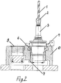
- the device shown in section serves for clamping a tool 1 by means of a clamping nut 2 and a collet (not shown) in a tool holder 3 Fig. 1 the device is shown for the sake of clarity without housing.
- a clamping ring 4 has a diameter corresponding to the outer diameter of the flange of the tool holder and is provided with a quick release 5 for quick clamping and unclamping of the tool holder.
- the clamping ring 4 is rigidly connected to a lever 7 via a cylindrical sleeve 6.
- the end of the lever rests on a pressure cell 8 which is hydraulically connected to a display device 9.
- the display device is calibrated according to the torque acting on the clamping nut.
- the functional parts of the device are arranged in a housing 10 which is connected to a base plate 11.
- the tightening nut can be tightened with any tool.
- a torque wrench is not required. If at one in the clamping ring engages a torque on the clamping nut by means of the quick-release tool holder, this acts directly on the lever 7 via the clamping ring 4 and the sleeve 6, which thereby presses the pressure load cell with a force corresponding to the torque.
- the resulting pressure in the pressure cell is transferred hydraulically to the display device and displayed as torque.
- another pressure measuring unit for example a piezoelectric sensor, can also be used.
- the clamping ring can be exchanged to adapt the device to different flange diameters of the tool holder.
Landscapes
- Engineering & Computer Science (AREA)
- Mechanical Engineering (AREA)
- Physics & Mathematics (AREA)
- General Physics & Mathematics (AREA)
- Chemical & Material Sciences (AREA)
- Analytical Chemistry (AREA)
- Machine Tool Sensing Apparatuses (AREA)
- Gripping On Spindles (AREA)
- Force Measurement Appropriate To Specific Purposes (AREA)
- Clamps And Clips (AREA)
Description
- Die Erfindung betrifft ein Spannsystem gemäss dem Oberbegriff des Anspruchs 1 (siehe z.B.
DE 10 2007 043 889 A1 ). - Beim Einspannen eines Werkzeugs in einen Werkzeughalter mittels einer Spannzange wird die konische Spannzange mit einer Spannmutter in den Aufnahmekonus einer Spannzangenaufnahme gepresst, wodurch die Segmente der Spannzange gegen den Werkzeugschaft gepresst werden. Dadurch wird das Werkzeug kraftschlüssig gehalten.
- Die Axialkraft, mit der die Spannzange eingepresst wird hängt direkt vom Drehmoment ab, das an der Spannmutter angreift. Dieses Drehmoment sollte innerhalb enger Grenzen eingehalten werden. Bei zu geringem Drehmoment ist der Kraftschluss zwischen Spannzange und Werkzeug zu klein, so dass ein Schlupf des Werkzeugs stattfinden kann. Bei zu grossem Drehmoment können Beschädigungen an der Spannmutter und der Werkzeugaufnahme erfolgen. Ausserdem kann eine Verformung der Spannmutter und der Werkzeugaufnahme stattfinden, die den Rundlauf des Werkzeugs beeinträchtigen kann. Das Einspannen sollte deshalb mit einem Drehmomentschlüssel erfolgen. Dies wird aber in der Praxis häufig nicht befolgt. Häufig wird in Ermangelung eines passenden Drehmomentschlüssels mit einem normalen Schlüssel das grösstmögliche Drehmoment (Hammer!) angewendet, mit den genannten Folgen.
- Der Erfindung liegt die Aufgabe zugrunde, eine Lösung dieses Problems zu finden und sicher zu stellen, dass das Einspannen eines Werkzeugs mit dem richtigen Drehmoment erfolgt.
- Erfindungsgemäss wird diese Aufgabe gelöst durch die kennzeichnenden Merkmale des Anspruchs 1.
- Im Folgenden wird anhand der beiliegenden Zeichnungen ein Ausführungsbeispiel der Erfindung beschrieben. Es zeigen:
- Fig. 1
- eine perspektivische Darstellung einer Einspannvorrichtung,
- Fig. 2
- eine Schnittdarstellung der in
Fig. 1 gezeigten Vorrichtung. - Die in
Fig. 1 perspektivisch und inFig. 2 im Schnitt gezeigte Vorrichtung dient zum Einspannen eines Werkzeugs 1 mittels einer Spannmutter 2 und einer Spannzange (nicht gezeigt) in einen Werkzeughalter 3. InFig. 1 ist die Vorrichtung der Übersichtlichkeit halber ohne Gehäuse gezeigt. - Ein Spannring 4 weist einen dem äusseren Durchmesser des Flansches des Werkzeughalters entsprechenden Durchmesser auf und ist mit einem Schnellspanner 5 zum schnellen Ein- und Ausspannen des Werkzeughalters versehen. Der Spannring 4 ist starr über eine zylindrische Hülse 6 mit einem Hebel 7 verbunden. Das Ende des Hebels liegt an einer Druckmessdose 8 an, die hydraulisch mit einer Anzeigeeinrichtung 9 verbunden ist. Die Anzeigeeinrichtung ist entsprechend dem an der Spannmutter angreifenden Drehmoment kalibriert.
- Die funktionalen Teile der Vorrichtung sind in einem Gehäuse 10 angeordnet, das mit einer Sockelplatte 11 verbunden ist.
- Mit der erfindungsgemässen Vorrichtung kann das Anziehen der Spannmutter mit einem beliebigen Werkzeug erfolgen. Ein Drehmomentschlüssel wird nicht benötigt. Wenn bei einem in den Spannring mittels des Schnellspanners eingespannten Werkzeughalter an der Spannmutter ein Drehmoment angreift, wirkt dieses über den Spannring 4 und der Hülse 6 direkt auf den Hebel 7, der dadurch mit einer dem Drehmoment entsprechenden Kraft auf die Druckmessdose drückt. Der dadurch in der Druckmessdose entstehende Druck wird hydraulisch auf die Anzeigevorrichtung übertragen und als Drehmoment angezeigt. Anstelle der Druckmessdose kann auch eine andere Druckmesseinheit, beispielweise ein piezoelektrischer Sensor, verwendet werden.
- Der Spannring ist zur Anpassung der Vorrichtung an unterschiedliche Flanschdurchmesser des Werkzeughalters auswechselbar.
Claims (2)
- Spannvorrichtung zum Einspannen eines Werkzeugs (1) mittels Spannzange und Spannmutter (2) in einen Werkzeughalter (3), gekennzeichnet durch- einen Spannring (4) zum Einspannen des Werkzeughalters,- einen mit dem Spannring starr verbundenen Hebel (7),- eine Druckmessdose (8), an der der Hebel anliegt und auf sie eine Kraft, die durch ein auf die Spannmutter ausgeübtes Drehmoment erzeugt wird, überträgt, und- eine mit der Messeinheit verbundene, entsprechend dem ausgeübten Drehmoment kalibrierte Anzeigeeinrichtung (9).
- Spannvorrichtung nach Anspruch 1, dadurch gekennzeichnet, dass der Spannring mit einem Schnellspanner (5) versehen ist.
Applications Claiming Priority (2)
| Application Number | Priority Date | Filing Date | Title |
|---|---|---|---|
| CH00725/16A CH712564A1 (de) | 2016-06-07 | 2016-06-07 | Spannvorrichtung zum Einspannen eines Werkzeugs in einen Werkzeughalter. |
| PCT/EP2017/063295 WO2017211676A1 (de) | 2016-06-07 | 2017-06-01 | Spannsystem |
Publications (2)
| Publication Number | Publication Date |
|---|---|
| EP3463747A1 EP3463747A1 (de) | 2019-04-10 |
| EP3463747B1 true EP3463747B1 (de) | 2020-08-05 |
Family
ID=59021488
Family Applications (1)
| Application Number | Title | Priority Date | Filing Date |
|---|---|---|---|
| EP17728509.5A Active EP3463747B1 (de) | 2016-06-07 | 2017-06-01 | Spannsystem |
Country Status (7)
| Country | Link |
|---|---|
| US (1) | US10807210B2 (de) |
| EP (1) | EP3463747B1 (de) |
| JP (1) | JP7063890B2 (de) |
| KR (1) | KR102380544B1 (de) |
| CN (1) | CN109641338A (de) |
| CH (1) | CH712564A1 (de) |
| WO (1) | WO2017211676A1 (de) |
Families Citing this family (2)
| Publication number | Priority date | Publication date | Assignee | Title |
|---|---|---|---|---|
| KR102671511B1 (ko) | 2019-01-30 | 2024-06-03 | 에이치엘만도 주식회사 | 엑츄에이터 및 이를 갖는 전기 기계식 디스크 브레이크 |
| US20230167854A1 (en) * | 2021-11-29 | 2023-06-01 | Shin-Yain Industrial Co., Ltd. | Tool holder bearing locking device |
Family Cites Families (42)
| Publication number | Priority date | Publication date | Assignee | Title |
|---|---|---|---|---|
| US2030464A (en) * | 1933-07-14 | 1936-02-11 | Gen Railway Signal Co | Testing device for threaded articles |
| US2281226A (en) * | 1939-09-11 | 1942-04-28 | Boles Younse | Apparatus and system for measuring torque |
| US3011332A (en) * | 1956-08-30 | 1961-12-05 | John W Wilhelm | Static torque measuring device |
| US3088313A (en) * | 1960-09-15 | 1963-05-07 | Western Electric Co | Torque testing apparatus |
| JPS5036779Y2 (de) * | 1972-03-13 | 1975-10-25 | ||
| US4117943A (en) * | 1976-10-04 | 1978-10-03 | General Dynamics Corporation | Device for pre-setting tools for numerical controlled machine |
| US4581808A (en) * | 1982-02-04 | 1986-04-15 | The Charles Stark Draper Laboratory | Adjustable machining system and implement therefore |
| JPS60232885A (ja) * | 1984-04-28 | 1985-11-19 | 大同機工株式会社 | トルク測定装置付きパワ−レンチ |
| JPS61270054A (ja) * | 1985-05-25 | 1986-11-29 | Nippon Pneumatic Kogyo Kk | 工具異常予知装置 |
| CH673100A5 (de) * | 1987-08-10 | 1990-02-15 | Josef Paul Huser | |
| JPH01121181A (ja) * | 1988-09-17 | 1989-05-12 | Daido Kiko Kk | トルク測定装置付きパワーレンチ |
| CN2042592U (zh) * | 1988-12-09 | 1989-08-09 | 陆建东 | 扭矩测量计 |
| DE3937466A1 (de) * | 1989-11-10 | 1991-05-16 | Heiko Dipl Ing Noske | Verfahren und vorrichtung zur ueberwachung der spannkraft bei werkzeugmaschinen |
| US4989459A (en) * | 1989-12-11 | 1991-02-05 | Bristol-Myers Squibb Company | Torque testing apparatus |
| US5109706A (en) * | 1990-07-06 | 1992-05-05 | Kennametal Inc. | Tightening fixture with built-in torque readout device |
| CN2121535U (zh) * | 1992-06-06 | 1992-11-11 | 石油大学(华东) | 杠杆链轮压力式钻机转盘扭矩仪 |
| IL102732A (en) | 1992-08-05 | 1995-01-24 | Iscar Ltd | Mechanical device for grasping tools in the adapter |
| US5597964A (en) * | 1995-06-06 | 1997-01-28 | Air Industries Corporation | Torque measuring device for free running self-locking nut and bolt combination |
| JP3359288B2 (ja) * | 1998-06-30 | 2002-12-24 | 政人 石井 | チャック |
| SE516966C2 (sv) * | 2001-03-21 | 2002-03-26 | Gustav Svensson | Förfarande och anordning för mätning och beräkning av överförbart vridande moment vid en verktygschuck eller liknande |
| CN2585206Y (zh) * | 2002-11-19 | 2003-11-05 | 谢智庆 | 简易型扭力测试装置 |
| DE10309897A1 (de) * | 2003-03-05 | 2004-09-16 | Albin Noe Gmbh | Kraftmessdose |
| SE528593C2 (sv) * | 2006-01-05 | 2006-12-27 | Gustav Svensson | Anordning för mätning av överförbart vridande moment vid en verktygschuck |
| DE102007043889A1 (de) * | 2006-10-26 | 2008-04-30 | Franz Haimer Maschinenbau Kg | Drehmomentschlüssel |
| US9205524B2 (en) * | 2009-01-16 | 2015-12-08 | John Wayne Stoneback | Test gauge |
| JP5404105B2 (ja) * | 2009-03-09 | 2014-01-29 | 株式会社日研工作所 | クランプ機構、およびこのクランプ機構を備えるスパナおよびツールクランパ |
| DE102009054185B3 (de) * | 2009-11-23 | 2011-04-14 | Eugen Fahrion Gmbh & Co. | Spannschlüssel |
| CN201628602U (zh) * | 2010-03-19 | 2010-11-10 | 黄岩 | 智能电动自行车后轴套式力矩传感装置 |
| SE1050589A1 (sv) * | 2010-06-08 | 2011-11-22 | Rocan System Ab | Anordning och metod för att indikera om ett fästelement vid infästning i ett stycke har uppnått en sträckgränsbelastning |
| CN102749161B (zh) * | 2011-04-20 | 2014-04-23 | 鸿富锦精密工业(深圳)有限公司 | 扭力测试装置 |
| US9527185B2 (en) * | 2011-09-12 | 2016-12-27 | John Wayne Stoneback | Test gauge |
| DE102014202151A1 (de) * | 2013-06-14 | 2015-01-08 | Eugen Fahrion Gmbh & Co. | Werkzeughalter, Spannzange und Verfahren zum Einspannen eines Werkzeugs in einem Werkzeughalter |
| US9915574B2 (en) * | 2014-03-11 | 2018-03-13 | The Boeing Company | Method and apparatus for measuring a preload of a fastener |
| US9702797B2 (en) * | 2014-09-01 | 2017-07-11 | ScienBiziP Consulting(Shenzhen)Co., Ltd. | Supporting apparatus and torsion test measuring device using same |
| CN104458095B (zh) * | 2014-12-04 | 2017-08-29 | 珠海健帆生物科技股份有限公司 | 血液净化耗材拧紧扭矩实时检测装置 |
| CN105277364A (zh) * | 2015-11-02 | 2016-01-27 | 常熟长城轴承有限公司 | 一种轴承摩擦力矩测量仪 |
| DE202015106965U1 (de) * | 2015-12-21 | 2016-02-01 | Esem Grünau GmbH & Co. KG | Messvorrichtung zum Überprüfen eines Spannfutters |
| US9696224B1 (en) * | 2015-12-31 | 2017-07-04 | Chung-Yu Tsai | Torque detection device |
| DE102017114536B3 (de) * | 2017-02-07 | 2018-07-05 | Schunk Gmbh & Co. Kg Spann- Und Greiftechnik | Verfahren und Vorrichtung zum Betätigen einer Hydro-Dehnspanneinrichtung |
| DE102017205024B4 (de) * | 2017-03-24 | 2019-05-23 | Hainbuch Gmbh Spannende Technik | Spannkraftmessgeräte und dessen Module |
| FR3074074B1 (fr) * | 2017-11-24 | 2019-11-01 | Societe D'assemblage Par Faisceaux D'electrons Et Laser (Safel) | Machine de soudage et/ou d'usinage, et procede de manipulation de pieces |
| US10345172B1 (en) * | 2018-02-21 | 2019-07-09 | E-Cube System Inc. | Apparatus for measuring axial force and frictional torque of threaded part and measuring method using the same |
-
2016
- 2016-06-07 CH CH00725/16A patent/CH712564A1/de not_active Application Discontinuation
-
2017
- 2017-06-01 CN CN201780035602.2A patent/CN109641338A/zh active Pending
- 2017-06-01 JP JP2019517149A patent/JP7063890B2/ja active Active
- 2017-06-01 WO PCT/EP2017/063295 patent/WO2017211676A1/de not_active Ceased
- 2017-06-01 US US16/307,556 patent/US10807210B2/en active Active
- 2017-06-01 KR KR1020187038216A patent/KR102380544B1/ko active Active
- 2017-06-01 EP EP17728509.5A patent/EP3463747B1/de active Active
Non-Patent Citations (1)
| Title |
|---|
| None * |
Also Published As
| Publication number | Publication date |
|---|---|
| JP2019521000A (ja) | 2019-07-25 |
| CH712564A1 (de) | 2017-12-15 |
| US10807210B2 (en) | 2020-10-20 |
| KR20190011784A (ko) | 2019-02-07 |
| EP3463747A1 (de) | 2019-04-10 |
| WO2017211676A1 (de) | 2017-12-14 |
| JP7063890B2 (ja) | 2022-05-09 |
| CN109641338A (zh) | 2019-04-16 |
| KR102380544B1 (ko) | 2022-03-29 |
| US20190299351A1 (en) | 2019-10-03 |
Similar Documents
| Publication | Publication Date | Title |
|---|---|---|
| DE112008002696B4 (de) | Drehmoment-Messflansch | |
| DE2460961C3 (de) | Vorrichtung zum Aufbringen einer Vorspannkraft auf einen Schraubenbolzen mit Mutter | |
| EP2977132A1 (de) | Werkzeugaufnahme zur Verbindung eines Diamantbohrgeräts mit einer Bohrkrone | |
| DE3151048A1 (de) | Spannkraftaufnehmer fuer umlaufende spanneinrichtungen | |
| DE102010026125A1 (de) | Spannvorrichtung zur lösbaren dreh- und axialfesten Fixierung von Werkzeugkomponenten | |
| WO2017211676A1 (de) | Spannsystem | |
| DE202022102184U1 (de) | Vorrichtung zur Verwendung in einer Druckprüfung für Rohre | |
| EP2081735A1 (de) | Vorrichtung zum anziehen und lösen von spannzeugen | |
| DE202013009347U1 (de) | Selbstzentrierende Aufspannvorrichtung für gedrechselte Schalen | |
| CH634244A5 (de) | Bohrfutter. | |
| DE3136286C2 (de) | ||
| DE2146251A1 (de) | Kaliberringziehvorrichtung | |
| DE912145C (de) | Befestigung fuer sich oder gegen Kupplungskoerper stossende Rohre | |
| DE102006033320B4 (de) | Schraubenvorspanneinrichtung | |
| DE102014220294A1 (de) | Spannsystem zum Vorspannen eines Zugangs einer Strömungskraftmaschine | |
| DE102019220389B4 (de) | Blechumformwerkzeug mit einem Niederhalter und Werkzeugpinole mit einer Kraftmesseinrichtung zur Übertragung der Niederhalterkraft | |
| DE102018109893A1 (de) | Spannfutter | |
| DE102017004043A1 (de) | Drehmomentschlüssel mit vordefinierter Drehmomentbegrenzung | |
| AT510413B1 (de) | Vorrichtung zum voreinstellen der einstecktiefe eines werkzeugs in eine werkzeugaufnahme | |
| EP3380805A1 (de) | Messanordnung mit einem taktilen messtaster und einem klemmhalter, sowie klemmhalter für einen taktilen messtaster | |
| DE102017104546A1 (de) | Laufklemmung für eine Schusswaffe | |
| DE530177C (de) | Loesbare Rohrkupplung | |
| DE605632C (de) | Vorrichtung zum Spannen und Loesen eines unter dem Schnittdruck selbsttaetig nachspannenden, auch zur Aufnahme unrunder Werkstuecke geeignten Mitnehmers fuer Drehbaenke | |
| DE112006000547B4 (de) | Hydraulikzylinderkolben | |
| DE841672C (de) | Mitnehmerspitze fuer Drehbankspindeln od. dgl. |
Legal Events
| Date | Code | Title | Description |
|---|---|---|---|
| STAA | Information on the status of an ep patent application or granted ep patent |
Free format text: STATUS: UNKNOWN |
|
| STAA | Information on the status of an ep patent application or granted ep patent |
Free format text: STATUS: THE INTERNATIONAL PUBLICATION HAS BEEN MADE |
|
| PUAI | Public reference made under article 153(3) epc to a published international application that has entered the european phase |
Free format text: ORIGINAL CODE: 0009012 |
|
| STAA | Information on the status of an ep patent application or granted ep patent |
Free format text: STATUS: REQUEST FOR EXAMINATION WAS MADE |
|
| 17P | Request for examination filed |
Effective date: 20190107 |
|
| AK | Designated contracting states |
Kind code of ref document: A1 Designated state(s): AL AT BE BG CH CY CZ DE DK EE ES FI FR GB GR HR HU IE IS IT LI LT LU LV MC MK MT NL NO PL PT RO RS SE SI SK SM TR |
|
| AX | Request for extension of the european patent |
Extension state: BA ME |
|
| DAV | Request for validation of the european patent (deleted) | ||
| DAX | Request for extension of the european patent (deleted) | ||
| GRAP | Despatch of communication of intention to grant a patent |
Free format text: ORIGINAL CODE: EPIDOSNIGR1 |
|
| STAA | Information on the status of an ep patent application or granted ep patent |
Free format text: STATUS: GRANT OF PATENT IS INTENDED |
|
| INTG | Intention to grant announced |
Effective date: 20200306 |
|
| GRAS | Grant fee paid |
Free format text: ORIGINAL CODE: EPIDOSNIGR3 |
|
| GRAA | (expected) grant |
Free format text: ORIGINAL CODE: 0009210 |
|
| STAA | Information on the status of an ep patent application or granted ep patent |
Free format text: STATUS: THE PATENT HAS BEEN GRANTED |
|
| AK | Designated contracting states |
Kind code of ref document: B1 Designated state(s): AL AT BE BG CH CY CZ DE DK EE ES FI FR GB GR HR HU IE IS IT LI LT LU LV MC MK MT NL NO PL PT RO RS SE SI SK SM TR |
|
| REG | Reference to a national code |
Ref country code: GB Ref legal event code: FG4D Free format text: NOT ENGLISH |
|
| REG | Reference to a national code |
Ref country code: CH Ref legal event code: EP |
|
| REG | Reference to a national code |
Ref country code: AT Ref legal event code: REF Ref document number: 1298051 Country of ref document: AT Kind code of ref document: T Effective date: 20200815 |
|
| REG | Reference to a national code |
Ref country code: DE Ref legal event code: R096 Ref document number: 502017006580 Country of ref document: DE |
|
| REG | Reference to a national code |
Ref country code: IE Ref legal event code: FG4D Free format text: LANGUAGE OF EP DOCUMENT: GERMAN |
|
| REG | Reference to a national code |
Ref country code: CH Ref legal event code: NV Representative=s name: BRAUNPAT BRAUN EDER AG, CH |
|
| REG | Reference to a national code |
Ref country code: LT Ref legal event code: MG4D |
|
| REG | Reference to a national code |
Ref country code: NL Ref legal event code: MP Effective date: 20200805 |
|
| PG25 | Lapsed in a contracting state [announced via postgrant information from national office to epo] |
Ref country code: ES Free format text: LAPSE BECAUSE OF FAILURE TO SUBMIT A TRANSLATION OF THE DESCRIPTION OR TO PAY THE FEE WITHIN THE PRESCRIBED TIME-LIMIT Effective date: 20200805 Ref country code: NO Free format text: LAPSE BECAUSE OF FAILURE TO SUBMIT A TRANSLATION OF THE DESCRIPTION OR TO PAY THE FEE WITHIN THE PRESCRIBED TIME-LIMIT Effective date: 20201105 Ref country code: BG Free format text: LAPSE BECAUSE OF FAILURE TO SUBMIT A TRANSLATION OF THE DESCRIPTION OR TO PAY THE FEE WITHIN THE PRESCRIBED TIME-LIMIT Effective date: 20201105 Ref country code: HR Free format text: LAPSE BECAUSE OF FAILURE TO SUBMIT A TRANSLATION OF THE DESCRIPTION OR TO PAY THE FEE WITHIN THE PRESCRIBED TIME-LIMIT Effective date: 20200805 Ref country code: LT Free format text: LAPSE BECAUSE OF FAILURE TO SUBMIT A TRANSLATION OF THE DESCRIPTION OR TO PAY THE FEE WITHIN THE PRESCRIBED TIME-LIMIT Effective date: 20200805 Ref country code: GR Free format text: LAPSE BECAUSE OF FAILURE TO SUBMIT A TRANSLATION OF THE DESCRIPTION OR TO PAY THE FEE WITHIN THE PRESCRIBED TIME-LIMIT Effective date: 20201106 Ref country code: FI Free format text: LAPSE BECAUSE OF FAILURE TO SUBMIT A TRANSLATION OF THE DESCRIPTION OR TO PAY THE FEE WITHIN THE PRESCRIBED TIME-LIMIT Effective date: 20200805 Ref country code: PT Free format text: LAPSE BECAUSE OF FAILURE TO SUBMIT A TRANSLATION OF THE DESCRIPTION OR TO PAY THE FEE WITHIN THE PRESCRIBED TIME-LIMIT Effective date: 20201207 Ref country code: SE Free format text: LAPSE BECAUSE OF FAILURE TO SUBMIT A TRANSLATION OF THE DESCRIPTION OR TO PAY THE FEE WITHIN THE PRESCRIBED TIME-LIMIT Effective date: 20200805 |
|
| PG25 | Lapsed in a contracting state [announced via postgrant information from national office to epo] |
Ref country code: LV Free format text: LAPSE BECAUSE OF FAILURE TO SUBMIT A TRANSLATION OF THE DESCRIPTION OR TO PAY THE FEE WITHIN THE PRESCRIBED TIME-LIMIT Effective date: 20200805 Ref country code: RS Free format text: LAPSE BECAUSE OF FAILURE TO SUBMIT A TRANSLATION OF THE DESCRIPTION OR TO PAY THE FEE WITHIN THE PRESCRIBED TIME-LIMIT Effective date: 20200805 Ref country code: PL Free format text: LAPSE BECAUSE OF FAILURE TO SUBMIT A TRANSLATION OF THE DESCRIPTION OR TO PAY THE FEE WITHIN THE PRESCRIBED TIME-LIMIT Effective date: 20200805 Ref country code: NL Free format text: LAPSE BECAUSE OF FAILURE TO SUBMIT A TRANSLATION OF THE DESCRIPTION OR TO PAY THE FEE WITHIN THE PRESCRIBED TIME-LIMIT Effective date: 20200805 Ref country code: IS Free format text: LAPSE BECAUSE OF FAILURE TO SUBMIT A TRANSLATION OF THE DESCRIPTION OR TO PAY THE FEE WITHIN THE PRESCRIBED TIME-LIMIT Effective date: 20201205 |
|
| PG25 | Lapsed in a contracting state [announced via postgrant information from national office to epo] |
Ref country code: DK Free format text: LAPSE BECAUSE OF FAILURE TO SUBMIT A TRANSLATION OF THE DESCRIPTION OR TO PAY THE FEE WITHIN THE PRESCRIBED TIME-LIMIT Effective date: 20200805 Ref country code: CZ Free format text: LAPSE BECAUSE OF FAILURE TO SUBMIT A TRANSLATION OF THE DESCRIPTION OR TO PAY THE FEE WITHIN THE PRESCRIBED TIME-LIMIT Effective date: 20200805 Ref country code: RO Free format text: LAPSE BECAUSE OF FAILURE TO SUBMIT A TRANSLATION OF THE DESCRIPTION OR TO PAY THE FEE WITHIN THE PRESCRIBED TIME-LIMIT Effective date: 20200805 Ref country code: EE Free format text: LAPSE BECAUSE OF FAILURE TO SUBMIT A TRANSLATION OF THE DESCRIPTION OR TO PAY THE FEE WITHIN THE PRESCRIBED TIME-LIMIT Effective date: 20200805 Ref country code: SM Free format text: LAPSE BECAUSE OF FAILURE TO SUBMIT A TRANSLATION OF THE DESCRIPTION OR TO PAY THE FEE WITHIN THE PRESCRIBED TIME-LIMIT Effective date: 20200805 |
|
| REG | Reference to a national code |
Ref country code: DE Ref legal event code: R097 Ref document number: 502017006580 Country of ref document: DE |
|
| PG25 | Lapsed in a contracting state [announced via postgrant information from national office to epo] |
Ref country code: AL Free format text: LAPSE BECAUSE OF FAILURE TO SUBMIT A TRANSLATION OF THE DESCRIPTION OR TO PAY THE FEE WITHIN THE PRESCRIBED TIME-LIMIT Effective date: 20200805 |
|
| PLBE | No opposition filed within time limit |
Free format text: ORIGINAL CODE: 0009261 |
|
| STAA | Information on the status of an ep patent application or granted ep patent |
Free format text: STATUS: NO OPPOSITION FILED WITHIN TIME LIMIT |
|
| PG25 | Lapsed in a contracting state [announced via postgrant information from national office to epo] |
Ref country code: SK Free format text: LAPSE BECAUSE OF FAILURE TO SUBMIT A TRANSLATION OF THE DESCRIPTION OR TO PAY THE FEE WITHIN THE PRESCRIBED TIME-LIMIT Effective date: 20200805 |
|
| 26N | No opposition filed |
Effective date: 20210507 |
|
| PG25 | Lapsed in a contracting state [announced via postgrant information from national office to epo] |
Ref country code: IT Free format text: LAPSE BECAUSE OF FAILURE TO SUBMIT A TRANSLATION OF THE DESCRIPTION OR TO PAY THE FEE WITHIN THE PRESCRIBED TIME-LIMIT Effective date: 20200805 |
|
| PG25 | Lapsed in a contracting state [announced via postgrant information from national office to epo] |
Ref country code: SI Free format text: LAPSE BECAUSE OF FAILURE TO SUBMIT A TRANSLATION OF THE DESCRIPTION OR TO PAY THE FEE WITHIN THE PRESCRIBED TIME-LIMIT Effective date: 20200805 |
|
| PG25 | Lapsed in a contracting state [announced via postgrant information from national office to epo] |
Ref country code: MC Free format text: LAPSE BECAUSE OF FAILURE TO SUBMIT A TRANSLATION OF THE DESCRIPTION OR TO PAY THE FEE WITHIN THE PRESCRIBED TIME-LIMIT Effective date: 20200805 |
|
| REG | Reference to a national code |
Ref country code: BE Ref legal event code: MM Effective date: 20210630 |
|
| PG25 | Lapsed in a contracting state [announced via postgrant information from national office to epo] |
Ref country code: LU Free format text: LAPSE BECAUSE OF NON-PAYMENT OF DUE FEES Effective date: 20210601 |
|
| PG25 | Lapsed in a contracting state [announced via postgrant information from national office to epo] |
Ref country code: IE Free format text: LAPSE BECAUSE OF NON-PAYMENT OF DUE FEES Effective date: 20210601 |
|
| PG25 | Lapsed in a contracting state [announced via postgrant information from national office to epo] |
Ref country code: FR Free format text: LAPSE BECAUSE OF NON-PAYMENT OF DUE FEES Effective date: 20210630 |
|
| PG25 | Lapsed in a contracting state [announced via postgrant information from national office to epo] |
Ref country code: BE Free format text: LAPSE BECAUSE OF NON-PAYMENT OF DUE FEES Effective date: 20210630 |
|
| PG25 | Lapsed in a contracting state [announced via postgrant information from national office to epo] |
Ref country code: CY Free format text: LAPSE BECAUSE OF FAILURE TO SUBMIT A TRANSLATION OF THE DESCRIPTION OR TO PAY THE FEE WITHIN THE PRESCRIBED TIME-LIMIT Effective date: 20200805 |
|
| PG25 | Lapsed in a contracting state [announced via postgrant information from national office to epo] |
Ref country code: HU Free format text: LAPSE BECAUSE OF FAILURE TO SUBMIT A TRANSLATION OF THE DESCRIPTION OR TO PAY THE FEE WITHIN THE PRESCRIBED TIME-LIMIT; INVALID AB INITIO Effective date: 20170601 |
|
| REG | Reference to a national code |
Ref country code: AT Ref legal event code: MM01 Ref document number: 1298051 Country of ref document: AT Kind code of ref document: T Effective date: 20220601 |
|
| PG25 | Lapsed in a contracting state [announced via postgrant information from national office to epo] |
Ref country code: AT Free format text: LAPSE BECAUSE OF NON-PAYMENT OF DUE FEES Effective date: 20220601 |
|
| PG25 | Lapsed in a contracting state [announced via postgrant information from national office to epo] |
Ref country code: MK Free format text: LAPSE BECAUSE OF FAILURE TO SUBMIT A TRANSLATION OF THE DESCRIPTION OR TO PAY THE FEE WITHIN THE PRESCRIBED TIME-LIMIT Effective date: 20200805 |
|
| PG25 | Lapsed in a contracting state [announced via postgrant information from national office to epo] |
Ref country code: MT Free format text: LAPSE BECAUSE OF FAILURE TO SUBMIT A TRANSLATION OF THE DESCRIPTION OR TO PAY THE FEE WITHIN THE PRESCRIBED TIME-LIMIT Effective date: 20200805 |
|
| PGFP | Annual fee paid to national office [announced via postgrant information from national office to epo] |
Ref country code: DE Payment date: 20250618 Year of fee payment: 9 |
|
| PGFP | Annual fee paid to national office [announced via postgrant information from national office to epo] |
Ref country code: GB Payment date: 20250618 Year of fee payment: 9 |
|
| PGFP | Annual fee paid to national office [announced via postgrant information from national office to epo] |
Ref country code: CH Payment date: 20250701 Year of fee payment: 9 |
|
| PG25 | Lapsed in a contracting state [announced via postgrant information from national office to epo] |
Ref country code: TR Free format text: LAPSE BECAUSE OF FAILURE TO SUBMIT A TRANSLATION OF THE DESCRIPTION OR TO PAY THE FEE WITHIN THE PRESCRIBED TIME-LIMIT Effective date: 20200805 |