EP3462964B1 - Einlegesohle für schuhe - Google Patents
Einlegesohle für schuhe Download PDFInfo
- Publication number
- EP3462964B1 EP3462964B1 EP17803174.6A EP17803174A EP3462964B1 EP 3462964 B1 EP3462964 B1 EP 3462964B1 EP 17803174 A EP17803174 A EP 17803174A EP 3462964 B1 EP3462964 B1 EP 3462964B1
- Authority
- EP
- European Patent Office
- Prior art keywords
- insole
- anterior
- arch support
- reinforcing bridge
- bridge
- Prior art date
- Legal status (The legal status is an assumption and is not a legal conclusion. Google has not performed a legal analysis and makes no representation as to the accuracy of the status listed.)
- Active
Links
- 230000003014 reinforcing effect Effects 0.000 claims description 177
- 230000006835 compression Effects 0.000 claims description 10
- 238000007906 compression Methods 0.000 claims description 10
- 210000002683 foot Anatomy 0.000 description 21
- 238000013016 damping Methods 0.000 description 12
- 210000001872 metatarsal bone Anatomy 0.000 description 9
- 239000000463 material Substances 0.000 description 7
- 210000003371 toe Anatomy 0.000 description 6
- 230000006378 damage Effects 0.000 description 4
- 210000000988 bone and bone Anatomy 0.000 description 3
- 239000002184 metal Substances 0.000 description 3
- 239000011359 shock absorbing material Substances 0.000 description 3
- 239000003381 stabilizer Substances 0.000 description 3
- 239000003351 stiffener Substances 0.000 description 3
- 238000005452 bending Methods 0.000 description 2
- 210000000459 calcaneus Anatomy 0.000 description 2
- 210000000474 heel Anatomy 0.000 description 2
- 230000000399 orthopedic effect Effects 0.000 description 2
- 230000032683 aging Effects 0.000 description 1
- 230000015572 biosynthetic process Effects 0.000 description 1
- 239000000470 constituent Substances 0.000 description 1
- 230000001419 dependent effect Effects 0.000 description 1
- 230000000694 effects Effects 0.000 description 1
- 239000006260 foam Substances 0.000 description 1
- 210000001624 hip Anatomy 0.000 description 1
- 210000003127 knee Anatomy 0.000 description 1
- 238000004519 manufacturing process Methods 0.000 description 1
- 239000004033 plastic Substances 0.000 description 1
- 229920003023 plastic Polymers 0.000 description 1
- 210000001137 tarsal bone Anatomy 0.000 description 1
Images


Classifications
-
- A—HUMAN NECESSITIES
- A43—FOOTWEAR
- A43B—CHARACTERISTIC FEATURES OF FOOTWEAR; PARTS OF FOOTWEAR
- A43B7/00—Footwear with health or hygienic arrangements
- A43B7/14—Footwear with health or hygienic arrangements with foot-supporting parts
- A43B7/1405—Footwear with health or hygienic arrangements with foot-supporting parts with pads or holes on one or more locations, or having an anatomical or curved form
- A43B7/141—Footwear with health or hygienic arrangements with foot-supporting parts with pads or holes on one or more locations, or having an anatomical or curved form having an anatomical or curved form
-
- A—HUMAN NECESSITIES
- A43—FOOTWEAR
- A43B—CHARACTERISTIC FEATURES OF FOOTWEAR; PARTS OF FOOTWEAR
- A43B17/00—Insoles for insertion, e.g. footbeds or inlays, for attachment to the shoe after the upper has been joined
-
- A—HUMAN NECESSITIES
- A43—FOOTWEAR
- A43B—CHARACTERISTIC FEATURES OF FOOTWEAR; PARTS OF FOOTWEAR
- A43B17/00—Insoles for insertion, e.g. footbeds or inlays, for attachment to the shoe after the upper has been joined
- A43B17/003—Insoles for insertion, e.g. footbeds or inlays, for attachment to the shoe after the upper has been joined characterised by the material
- A43B17/006—Insoles for insertion, e.g. footbeds or inlays, for attachment to the shoe after the upper has been joined characterised by the material multilayered
-
- A—HUMAN NECESSITIES
- A43—FOOTWEAR
- A43B—CHARACTERISTIC FEATURES OF FOOTWEAR; PARTS OF FOOTWEAR
- A43B17/00—Insoles for insertion, e.g. footbeds or inlays, for attachment to the shoe after the upper has been joined
- A43B17/02—Insoles for insertion, e.g. footbeds or inlays, for attachment to the shoe after the upper has been joined wedge-like or resilient
-
- A—HUMAN NECESSITIES
- A43—FOOTWEAR
- A43B—CHARACTERISTIC FEATURES OF FOOTWEAR; PARTS OF FOOTWEAR
- A43B17/00—Insoles for insertion, e.g. footbeds or inlays, for attachment to the shoe after the upper has been joined
- A43B17/06—Insoles for insertion, e.g. footbeds or inlays, for attachment to the shoe after the upper has been joined with metal springs
-
- A—HUMAN NECESSITIES
- A43—FOOTWEAR
- A43B—CHARACTERISTIC FEATURES OF FOOTWEAR; PARTS OF FOOTWEAR
- A43B17/00—Insoles for insertion, e.g. footbeds or inlays, for attachment to the shoe after the upper has been joined
- A43B17/14—Insoles for insertion, e.g. footbeds or inlays, for attachment to the shoe after the upper has been joined made of sponge, rubber, or plastic materials
-
- A—HUMAN NECESSITIES
- A43—FOOTWEAR
- A43B—CHARACTERISTIC FEATURES OF FOOTWEAR; PARTS OF FOOTWEAR
- A43B23/00—Uppers; Boot legs; Stiffeners; Other single parts of footwear
- A43B23/22—Supports for the shank or arch of the uppers
- A43B23/222—Supports for the shank or arch of the uppers characterised by the attachment to the sole
-
- A—HUMAN NECESSITIES
- A43—FOOTWEAR
- A43B—CHARACTERISTIC FEATURES OF FOOTWEAR; PARTS OF FOOTWEAR
- A43B7/00—Footwear with health or hygienic arrangements
- A43B7/14—Footwear with health or hygienic arrangements with foot-supporting parts
- A43B7/1405—Footwear with health or hygienic arrangements with foot-supporting parts with pads or holes on one or more locations, or having an anatomical or curved form
- A43B7/1415—Footwear with health or hygienic arrangements with foot-supporting parts with pads or holes on one or more locations, or having an anatomical or curved form characterised by the location under the foot
- A43B7/142—Footwear with health or hygienic arrangements with foot-supporting parts with pads or holes on one or more locations, or having an anatomical or curved form characterised by the location under the foot situated under the medial arch, i.e. under the navicular or cuneiform bones
-
- A—HUMAN NECESSITIES
- A43—FOOTWEAR
- A43B—CHARACTERISTIC FEATURES OF FOOTWEAR; PARTS OF FOOTWEAR
- A43B7/00—Footwear with health or hygienic arrangements
- A43B7/14—Footwear with health or hygienic arrangements with foot-supporting parts
- A43B7/1405—Footwear with health or hygienic arrangements with foot-supporting parts with pads or holes on one or more locations, or having an anatomical or curved form
- A43B7/1415—Footwear with health or hygienic arrangements with foot-supporting parts with pads or holes on one or more locations, or having an anatomical or curved form characterised by the location under the foot
- A43B7/1425—Footwear with health or hygienic arrangements with foot-supporting parts with pads or holes on one or more locations, or having an anatomical or curved form characterised by the location under the foot situated under the ball of the foot, i.e. the joint between the first metatarsal and first phalange
-
- A—HUMAN NECESSITIES
- A43—FOOTWEAR
- A43B—CHARACTERISTIC FEATURES OF FOOTWEAR; PARTS OF FOOTWEAR
- A43B7/00—Footwear with health or hygienic arrangements
- A43B7/14—Footwear with health or hygienic arrangements with foot-supporting parts
- A43B7/1405—Footwear with health or hygienic arrangements with foot-supporting parts with pads or holes on one or more locations, or having an anatomical or curved form
- A43B7/1415—Footwear with health or hygienic arrangements with foot-supporting parts with pads or holes on one or more locations, or having an anatomical or curved form characterised by the location under the foot
- A43B7/143—Footwear with health or hygienic arrangements with foot-supporting parts with pads or holes on one or more locations, or having an anatomical or curved form characterised by the location under the foot situated under the lateral arch, i.e. the cuboid bone
-
- A—HUMAN NECESSITIES
- A43—FOOTWEAR
- A43B—CHARACTERISTIC FEATURES OF FOOTWEAR; PARTS OF FOOTWEAR
- A43B7/00—Footwear with health or hygienic arrangements
- A43B7/14—Footwear with health or hygienic arrangements with foot-supporting parts
- A43B7/1405—Footwear with health or hygienic arrangements with foot-supporting parts with pads or holes on one or more locations, or having an anatomical or curved form
- A43B7/1415—Footwear with health or hygienic arrangements with foot-supporting parts with pads or holes on one or more locations, or having an anatomical or curved form characterised by the location under the foot
- A43B7/1445—Footwear with health or hygienic arrangements with foot-supporting parts with pads or holes on one or more locations, or having an anatomical or curved form characterised by the location under the foot situated under the midfoot, i.e. the second, third or fourth metatarsal
-
- A—HUMAN NECESSITIES
- A43—FOOTWEAR
- A43B—CHARACTERISTIC FEATURES OF FOOTWEAR; PARTS OF FOOTWEAR
- A43B7/00—Footwear with health or hygienic arrangements
- A43B7/14—Footwear with health or hygienic arrangements with foot-supporting parts
- A43B7/1405—Footwear with health or hygienic arrangements with foot-supporting parts with pads or holes on one or more locations, or having an anatomical or curved form
- A43B7/1475—Footwear with health or hygienic arrangements with foot-supporting parts with pads or holes on one or more locations, or having an anatomical or curved form characterised by the type of support
- A43B7/148—Recesses or holes filled with supports or pads
-
- A—HUMAN NECESSITIES
- A61—MEDICAL OR VETERINARY SCIENCE; HYGIENE
- A61F—FILTERS IMPLANTABLE INTO BLOOD VESSELS; PROSTHESES; DEVICES PROVIDING PATENCY TO, OR PREVENTING COLLAPSING OF, TUBULAR STRUCTURES OF THE BODY, e.g. STENTS; ORTHOPAEDIC, NURSING OR CONTRACEPTIVE DEVICES; FOMENTATION; TREATMENT OR PROTECTION OF EYES OR EARS; BANDAGES, DRESSINGS OR ABSORBENT PADS; FIRST-AID KITS
- A61F5/00—Orthopaedic methods or devices for non-surgical treatment of bones or joints; Nursing devices; Anti-rape devices
- A61F5/01—Orthopaedic devices, e.g. splints, casts or braces
- A61F5/14—Special medical insertions for shoes for flat-feet, club-feet or the like
Definitions
- the present disclosure generally relates to insoles for footwear.
- an insole comprising at least one reinforcing bridge and a footwear comprising the insole are provided.
- insoles in order to improve the anatomical position of the foot in the shoe and prevent injuries and/or pain.
- Some insoles provide support to the three arches of the foot: the anterior arch, the medial arch and the lateral arch, for example by means of inserts in the insole or by means of locally thicker regions in the insole.
- US 20130111781 A1 discloses an orthopaedic shoe insert to support and guide the foot.
- the shoe insert comprises an insert core having a carrier and a support clasp.
- the support clasp comprises two individually adjustable diagonally opposite support arms having a higher mechanical strength.
- the insert may comprise a pad in a front toe area of the foot, in order to achieve soft or resilient cushioning of the foot in this area.
- FR 2842710 A1 discloses an insole comprising a convex formation and a medial element.
- the medial element is made of foam.
- WO 2006040415 A1 discloses an orthopedic sole comprising a transverse anterior element, two metal blades and lateral wings having a spring effect obtained by virtue of the two metal blades.
- the transverse anterior element comprises an ovoid protuberance and a front edge.
- Some prior art insoles comprise arch supports with an initial shape when the insole or shoe is new.
- many of these prior art arch supports change in shape over time when the shoe is used, for example due to compression forces from the wearer's weight, impacts, moisture, material ageing and/or exposure to sunlight.
- the arch supports might lose their intended function and the wearer might get injuries in the feet, knees, hip and/or back.
- the shoe might also become painful to wear.
- One object of the present disclosure is to provide an insole that gives an anatomically correct support to the anterior arch of the foot and maintains this support over time.
- a further object of the present disclosure is to provide an insole that gives an anatomically correct support to the medial arch and the lateral arch of the foot and maintains this support over time.
- a still further object of the present disclosure is to provide an insole that reduces twisting of the insole about a longitudinal axis of the insole.
- a still further object of the present disclosure is to provide an insole that has good flexibility to allow the foot to move during walking and/or running.
- a still further object of the present disclosure is to provide an insole that has a simple structure and enables a simple and cheap production.
- a still further object of the present disclosure is to provide an insole that has a low weight.
- the invention relates to an insole for footwear as specified in appended independent claim 1. Preferred embodiments of the invention are disclosed in the dependent claims.
- the invention relates to an insole for footwear, the insole comprising:
- the anterior reinforcing bridge thus adds rigidity to the anterior arch support and contributes to maintaining the original shape of the anterior arch support over time.
- the anterior reinforcing bridge may alternatively be referred to as an anterior stiffener, an anterior stabilizer, an anterior beam or an anterior bar.
- the anterior arch support of the insole may comprise or be constituted by a shock absorbing material or damping material (e.g. PORON ®).
- the damping material may be locally provided to the anterior arch support.
- the insole may comprise a damping layer. This damping layer may have a substantially uniform thickness but once laid upon the anterior reinforcing bridge it may define the anterior arch support of the insole.
- the anterior arch support may have a generally circular or droplet shaped appearance. If a droplet shape is employed, the droplet may point backwards in a longitudinal direction of the insole, i.e. towards a heel region of the insole. The anterior arch support may be successively vertically raised with respect to the adjacent surface of the insole.
- the anterior arch support may have a maximum length in the longitudinal direction of the insole that is 10% to 30%, such as 15% to 25%, such as 18% to 22%, such as 20%, of the length of the insole in the longitudinal direction.
- the anterior arch support may have a maximum length in the lateral direction (width direction) of the insole that is 40% to 60%, such as 45% to 55%, such as 48% to 52%, such as 50%, of the local width of the insole in the lateral direction where the anterior arch support is provided.
- the anterior arch support may be positioned (e.g. with its geometrical center point) at a distance from a front tip of the insole that is 35% to 45%, such as 38% to 42%, such as 40%, of the longitudinal length of the insole.
- the anterior arch support may be substantially centered in the lateral direction of the insole.
- the anterior reinforcing bridge may extend substantially in a lateral direction of the insole.
- the anterior reinforcing bridge may have an elongated appearance.
- the anterior reinforcing bridge may be substantially straight.
- the anterior reinforcing bridge may be positioned (e.g. with its geometrical center point) at a distance from a front tip of the insole that is 30% to 50%, such as 35% to 45%, such as 37% to 41%, such as 39%, of the longitudinal length of the insole.
- the anterior reinforcing bridge may have a width in the longitudinal direction of the insole that is 2% to 6%, such as 4%, of the longitudinal length of the insole.
- the anterior reinforcing bridge may have a width in the longitudinal direction of the insole of 5 to 15 mm, such as 8 to 12 mm, such as 9 to 11 mm, such as 10 mm.
- the length of the anterior reinforcing bridge may be independent of the size of the footwear.
- the raised section of the anterior reinforcing bridge may span over substantially the entire width of the insole.
- the anterior reinforcing bridge may have a generally arc shaped appearance.
- the raised section of the anterior reinforcing bridge may only span over a partial distance (e.g. a central section) of the width of the insole.
- the raised section may be an intermediate raised section of the anterior reinforcing bridge arranged between two further sections (e.g. two substantially flat sections).
- the intermediate raised section may have a length in the lateral direction that is 30% to 70%, such as 40 to 60%, such as 50%, of the local lateral width of the insole where the anterior reinforcing bridge is provided.
- a substantially perpendicular/parallel relationship includes a perfectly perpendicular/parallel relationship as well as deviations from a perfectly perpendicular/parallel relationship with up to 10%, such as up to 5%, such as up to 2%.
- a substantially corresponding distance as used herein includes a perfectly corresponding distance as well as deviations from a perfectly corresponding distance with up to 10%, such as up to 5%, such as up to 2%.
- the anterior reinforcing bridge is convex as seen in an anterior direction of the insole.
- the anterior reinforcing bridge has thus a substantially downwardly directed cavity and/or a substantially upwardly directed bulge.
- An anterior direction of the insole and a forward longitudinal direction of the insole as used herein are intended to be the same direction. These directions are directions along the anterior axis or the longitudinal axis of the insole.
- the insole may further comprise a medial arch support; a lateral arch support; and at least one transverse reinforcing bridge having two raised sections for providing resistance against compression of the medial arch support and the lateral arch support, respectively.
- Each of the medial arch support and the lateral arch support may have a generally arch shaped appearance as seen from above.
- the arc may point inwards substantially in the lateral direction of the insole.
- the medial arch support and the lateral arch support may be successively vertically raised with respect to the adjacent surface of the insole.
- the at least one transverse reinforcing bridge thus adds rigidity to the medial arch support and the lateral arch support and contributes to maintaining the original shape of the medial arch support and the lateral arch support over time. Moreover, the at least one transverse reinforcing bridge prevents the insole from bending about a central longitudinal axis.
- the transverse reinforcing bridge may alternatively be referred to as a transverse stiffener, a transverse stabilizer, a transverse beam or a transverse bar.
- the medial arch support may have a length in the longitudinal direction of the insole that is 35% to 60%, such as 40% to 55%, such as 45% to 50%, such as 48%, of the length of the insole in the longitudinal direction.
- the lateral arch support may have a length in the longitudinal direction of the insole that is 40% to 65%, such as 45% to 60%, such as 50% to 55%, such as 53%, of the length of the insole in the longitudinal direction.
- the medial arch support may be positioned (e.g. with its geometrical center point) at a distance from a front tip of the insole that is 55% to 70%, such as 60% to 65%, such as 63%, of the longitudinal length of the insole.
- the lateral arch support may be positioned (e.g. with its geometrical center point) at a distance from a front tip of the insole that is 55% to 70%, such as 60% to 65%, such as 63%, of the longitudinal length of the insole.
- the medial arch support and the lateral arch support of the insole may comprise or be constituted by a shock absorbing material or a damping material (e.g. PORON ®).
- the damping material may be locally provided to the medial arch support and the lateral arch support, respectively.
- the insole may comprise a damping layer. This damping layer may have a substantially uniform thickness but once laid upon the one or more transverse reinforcing bridges, it may define the medial arch support and the lateral arch support of the insole.
- each transverse reinforcing bridge may extend substantially in a lateral direction of the insole.
- each transverse reinforcing bridge may have an elongated appearance.
- the at least one transverse reinforcing bridge may extend substantially in a lateral direction of the insole.
- the insole may comprise two substantially parallel transverse reinforcing bridges.
- a first anterior transverse reinforcing bridge may be positioned (e.g. with its geometrical center point) at a distance from a front tip of the insole that is 50% to 65%, such as 55% to 60%, such as 57%, of the longitudinal length of the insole.
- a second posterior transverse reinforcing bridge may be positioned (e.g. with its geometrical center point) at a distance from a front tip of the insole that is 65% to 75%, such as 68% to 72%, such as 70%, of the longitudinal length of the insole.
- Each of these two transverse reinforcing bridges may have a width in the longitudinal direction of the insole that is 2% to 6%, such as 4%, of the longitudinal length of the insole.
- the transverse reinforcing bridge may have a width in the longitudinal direction of the insole of 5 to 15 mm, such as 8 to 12 mm, such as 9 to 11 mm, such as 10 mm.
- the width of the transverse reinforcing bridge may be independent of the size of the footwear.
- the insole may comprise only one single transverse reinforcing bridge.
- This single transverse reinforcing bridge may be constituted by one of the two transverse reinforcing bridges as described above and positioned at one of the described positions.
- such single transverse reinforcing bridge may be positioned (e.g. with its geometrical center point) at a distance from a front tip of the insole that is 55% to 75%, such as 60% to 70%, such as 62% to 66%, such as 64%, of the longitudinal length of the insole.
- the insole may comprise only one relatively wider single transverse reinforcing bridge.
- This single transverse reinforcing bridge may be positioned (e.g. with its geometrical center point) at a distance from a front tip of the insole that is 55% to 75%, such as 60% to 70%, such as 62% to 66%, such as 64%, of the longitudinal length of the insole.
- the width of such relatively wider single transverse reinforcing bridge in the longitudinal direction of the insole may be 10% to 30%, such as 15% to 25%, such as 17% to 21%, such as 19% of the longitudinal length of the insole.
- the single wider transverse reinforcing bridge may have a width in the longitudinal direction of the insole of 30 to 60 mm, such as 40 to 50 mm, such as 45 mm.
- the length of the transverse reinforcing bridge may be independent of the size of the footwear.
- the at least one transverse reinforcing bridge may be concave as seen in an anterior direction of the insole.
- the at least one transverse reinforcing bridge may thus have a substantially upwardly directed cavity and/or a substantially downwardly directed bulge.
- the at least one transverse reinforcing bridge may have a continuous concave arc shape.
- the two ends of the arc shape may constitute the respective raised sections of the transverse reinforcing bridge.
- the at least one transverse reinforcing bridge may comprise a substantially straight intermediate section between two outer curved sections constituting the respective raised section of the transverse reinforcing bridge.
- the at least one transverse reinforcing bridge may have a general shape of a widened "U".
- the length of the intermediate section of the transverse reinforcing bridge may be 40% to 55%, such as 45% to 50%, such as 48%, of the local lateral width of the insole where the transverse reinforcing bridge is provided.
- Such intermediate section of the transverse reinforcing bridge may span between the lateral arch support and the medial arch support.
- the insole may further comprise at least one oblique reinforcing bridge inclined with respect to an anterior direction of the insole.
- Each of the oblique reinforcing bridges may extend at an angle with respect to the anterior direction or the longitudinal direction of the insole from a posterior, medial point to an anterior lateral point of the insole.
- a mirrored configuration of the at least one oblique reinforcing bridge is also possible.
- each oblique reinforcing bridge may extend at an angle with respect to the longitudinal direction of the insole that is 30° to 45°, such as 35° to 40°, such as 37°.
- the at least one oblique reinforcing bridge thus adds rigidity to the medial arch support and the lateral arch support and contributes to maintaining the original shape of the medial arch support and the lateral arch support over time. Moreover, the at least one oblique reinforcing bridge prevents the insole from twisting about its longitudinal axis.
- the oblique reinforcing bridge may alternatively be referred to as an oblique stiffener, an oblique stabilizer, an oblique beam or an oblique bar.
- the insole may comprise two oblique reinforcing bridges.
- a first oblique reinforcing bridge may extend from a posterior point of the medial arch support to an anterior point of the lateral arch support.
- a second oblique reinforcing bridge may be arranged posterior of the first oblique reinforcing bridge and may also extend from a posterior point of the medial arch support to an anterior point of the lateral arch support.
- the first and second oblique reinforcing bridges may be substantially parallel.
- Each oblique reinforcing bridge may have an elongated appearance. As seen from above, each oblique reinforcing bridge may be substantially straight. Moreover, each oblique reinforcing bridge may have a width in a direction substantially perpendicular to its general extension direction of 5 to 15 mm, such as 8 to 12 mm, such as 9 to 11 mm, such as 10 mm.
- the insole may comprise only one single oblique reinforcing bridge.
- This single oblique reinforcing bridge may be constituted by one of the two oblique reinforcing bridge as described above.
- such single oblique reinforcing bridge may optionally be widened.
- such widened oblique reinforcing bridge may have a width in a direction substantially perpendicular to its general extension direction of 30 to 50 mm, such as 35 to 45 mm, such as 40 mm.
- the at least one oblique reinforcing bridge may comprise one or two raised sections for providing resistance against compression of one or both of the medial arch support and/or the lateral arch support.
- the at least one oblique reinforcing bridge may have a continuous concave arc shape.
- the two ends of the arc shape may constitute the respective raised sections of the oblique reinforcing bridge.
- the at least one oblique reinforcing bridge may comprise a substantially straight intermediate section between two outer curved sections constituting the respective raised section of the oblique reinforcing bridge.
- the at least one oblique reinforcing bridge may have a general shape of a widened "U".
- the intermediate section of the transverse reinforcing bridge may span between the lateral arch support and the medial arch support.
- a first anterior oblique reinforcing bridge may comprise only one raised section connected to a substantially straight section.
- the single raised section of the first anterior oblique reinforcing bridge may be arranged to support the medial arch support.
- a second posterior oblique reinforcing bridge may comprise a substantially straight intermediate section between two outer curved sections constituting the raised sections to support both the medial arch support and the lateral arch support.
- the second posterior oblique reinforcing bridge may comprise only one raised section connected to a substantially straight section.
- the single raised section of the second posterior oblique reinforcing bridge may be arranged to support the lateral arch support.
- Each reinforcing bridge as referred to herein may be a sheet of metal or hard plastics.
- the insole may further comprise a top layer, a bottom layer and a bridge layer wherein the bridge layer comprises the one or more reinforcing bridges.
- the bridge layer may be an intermediate layer, i.e. provided between the top layer and the bottom layer.
- the insole may further comprise a damping layer.
- the damping layer may be an intermediate layer, i.e. provided between the top layer and the bottom layer.
- the insole may comprise, in order from the top of the insole: the top layer, the damping layer, the bridge layer and the bottom layer. Additional layers may or may not be provided.
- the bridge layer may only comprise the one or more reinforcing bridges.
- the one or more reinforcing bridges may be the only constituent(s) of the bridge layer.
- a footwear comprising an insole according to the present disclosure.
- the footwear may for example be shoes, boots, sandals or slippers.
- the insole may be a partial insole.
- Such partial insole may be constituted by an insert.
- the insole is constituted by a partial insole, the examples of positions, dimensions and orientations as given above apply with respect to a length and width of the inside of the footwear in which the insole is provided or is to be provided.
- the insole may be integrally formed with the footwear.
- an insole comprising at least one reinforcing bridge and a footwear comprising the insole will be described.
- the same reference numerals will be used to denote the same or similar structural features.
- FIG. 1 schematically represents a bottom view of a foot 10.
- a typical foot 10 (here a right foot) comprises an anterior transverse arch or anterior arch illustrated by the lines 12, 14, a lateral longitudinal arch or a lateral arch illustrated by the lines 14, 16, and a medial longitudinal arch or medial arch illustrated by the lines 12, 16.
- Fig. 2 schematically represents a lateral side view of bones in the foot 10.
- the foot 10 comprises five metatarsals or metatarsal bones 18 located between the tarsal bones 20 and the phalanges.
- the phalanges are the bones in the toes and each toe except the large toe comprises a proximal phalange 22, an intermediate phalange and a distal phalange 24.
- the large toe only has two phalanges 22, 24.
- a metatarsal phalangeal joint 26 joins each metatarsal 18 to a respective proximal phalange 22.
- the metatarsal heads 28 are the ends of the metatarsals 18 closest to the proximal phalanges 22.
- the anterior arch 12, 14 is located below the metatarsal heads 28.
- the medial arch 12, 16 spans from below the first metatarsal head 28 to below the calcaneus 30.
- the lateral arch spans from below the fifth metatarsal head 28 to below the calcaneus 30.
- Fig. 2 further illustrates a vertical direction 32 with respect to the foot 10.
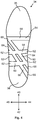
- Fig. 3 schematically represents a top view of an insole 34.
- the insole 34 comprises a toe region 36 and a heel region 38.
- the insole 34 may be inserted in various types of footwear.
- a coordinate system showing an anterior direction 40, a posterior direction 42, a medial direction 44 and a lateral direction 46.
- the anterior direction 40 may alternatively be referred to as a forward longitudinal direction and the posterior direction 42 may alternatively be referred to as a rearward longitudinal direction.
- the lateral direction 46 may alternatively be referred to as a lateral right direction and the medial direction 44 may alternatively be referred to as a lateral left direction.
- the insole 34 comprises an anterior arch support 48, a medial arch support 50 and a lateral arch support 52.
- Each of the anterior arch support 48, the medial arch support 50 and the lateral arch support 52 is raised vertically with respect to the respective adjacent surfaces of the insole 34.
- the anterior arch support 48 has a general droplet shape where the tip of the droplet points in the posterior direction 42.
- the anterior arch support 48 is substantially centered in the lateral direction 46 of the insole 34.
- the anterior arch support 48 has a maximum length in the longitudinal direction of the insole 34 that is approximately 20% of the length of the insole 34 in the longitudinal direction 40. Moreover, the anterior arch support 48 has a maximum length in the width direction (i.e. in the lateral direction 46) of the insole 34 that is approximately 50%, of the local width of the insole 34 in the lateral direction 46 where the anterior arch support 48 is provided. Moreover, the anterior arch support 48 is positioned with its geometrical center point at a distance from a front tip of the insole 34 that is approximately 40% of the longitudinal length of the insole 34.
- each of the medial arch support 50 and the lateral arch support 52 has a generally arch shaped appearance with an inwardly pointing arc.
- Each of the anterior arch support 48, the medial arch support 50 and the lateral arch support 52 is successively vertically raised with respect to the respective adjacent surface of the insole 34.
- the medial arch support 50 has a length in the longitudinal direction 40 of the insole 34 that is approximately 48% of the length of the insole 34 in the longitudinal direction 40.
- the lateral arch support 52 has a length in the longitudinal direction 40 of the insole 34 that is approximately 53% of the length of the insole 34 in the longitudinal direction 40.
- Each of the medial arch support 50 and the lateral arch support 52 is positioned with its geometrical center point at a distance from a front tip of the insole 34 that is approximately 63% of the longitudinal length of the insole 34.
- the anterior arch support 48, the medial arch support 50 and the lateral arch support 52 of this implementation comprises a shock absorbing material.
- Fig. 4 schematically represents a bottom view of the insole 34 and Fig. 5 schematically represents a top view of the insole 34 and where hidden reinforcing bridges are illustrated with dashed lines.
- the insole 34 comprises an anterior reinforcing bridge 54.
- the anterior reinforcing bridge 54 comprises a raised section 56 for providing rigidity, strength and compression resistance to the anterior arch support 48 over time.
- the anterior reinforcing bridge 54 has an elongated appearance and extends substantially in the lateral direction 46 of the insole 34.
- the anterior reinforcing bridge 54 is positioned with its geometrical center point at a distance from a front tip of the insole 34 that is approximately 39% of the longitudinal length of the insole 34.
- the anterior reinforcing bridge 54 has a width in the longitudinal direction 40 of the insole 34 that is approximately 4% of the longitudinal length of the insole 34 and/or approximately 10 mm.
- the insole 34 further comprises two transverse reinforcing bridges 58, 60.
- Each transverse reinforcing bridge 58, 60 has two raised sections 62 for providing resistance against compression of the medial arch support 50 and the lateral arch support 52, respectively.
- the transverse reinforcing bridges 58, 60 thus adds rigidity to the medial arch support 50 and the lateral arch support 52 and contributes to maintaining the original shape of the medial arch support 50 and the lateral arch support 52 over time.
- the two transverse reinforcing bridges 58, 60 prevent the insole 34 from bending about a central longitudinal axis.
- Each of the two transverse reinforcing bridges 58, 60 has an elongated appearance and extends substantially in the lateral direction 46 of the insole 34.
- the first anterior transverse reinforcing bridge 58 is positioned with its geometrical center point at a distance from the front tip of the insole 34 that is approximately 57% of the longitudinal length of the insole 34.
- the second posterior transverse reinforcing bridge 60 is positioned with its geometrical center point at a distance from a front tip of the insole 34 that is approximately 70% of the longitudinal length of the insole 34.
- Each of the two transverse reinforcing bridges 58, 60 has a width in the longitudinal direction 40 of the insole 34 that is approximately 4% of the longitudinal length of the insole 34 and/or approximately 10 mm.
- the insole 34 further comprises two substantially parallel oblique reinforcing bridges 64, 66 inclined with respect to the longitudinal axis 40 of the insole 34.
- Each of the oblique reinforcing bridges 64, 66 has an elongated appearance and extends at an angle with respect to the longitudinal axis 40 of the insole 34 from a posterior, medial point to an anterior lateral point of the insole 34 at an angle with respect to the longitudinal direction 40 of the insole 34 that is approximately 37°.
- the anterior oblique reinforcing bridge 64 extends from a posterior point of the medial arch support 50 to an anterior point of the lateral arch support 52.
- the posterior oblique reinforcing bridge 66 also extends from a posterior point of the medial arch support 50 to an anterior point of the lateral arch support 52.
- Each oblique reinforcing bridge 64, 66 has a width of approximately 10 mm.
- Each oblique reinforcing bridge 64, 66 comprises two raised sections 68 for providing resistance against compression of the medial arch support 50 and/or the lateral arch support 52. However, one or both of the oblique reinforcing bridge 64, 66 may only comprise one raised section 68 or no raised section 68.
- the two oblique reinforcing bridges 64, 66 add rigidity to the medial arch support 50 and the lateral arch support 52 and contribute to maintaining the original shape of the medial arch support 50 and the lateral arch support 52 over time. Moreover, the two oblique reinforcing bridges 64, 66 prevent the insole 34 from twisting about the longitudinal axis 40.
- the oblique reinforcing bridges 64, 66 are connected to the transverse reinforcing bridges 58, 60 at their crossing areas.
- the anterior oblique reinforcing bridge 64 is connected to the anterior reinforcing bridge 54 at their crossing area.
- all or some of the reinforcing bridges 54, 58, 60 64, 66 may be integrally formed.
- the reinforcing bridges 54, 58, 60 64, 66 may constitute a bridge layer.
- a bottom layer may cover the reinforcing bridges 54, 58, 60, 64, 66.
- a damping layer may further be provided between a top layer and the bridge layer.
- Fig. 6a schematically represents an anterior view of an anterior reinforcing bridge 54.
- the raised section 56 of the anterior reinforcing bridge 54 is raised in the vertical direction 32.
- the raised section 56 of this anterior reinforcing bridge 54 has a generally arc shaped appearance and spans over substantially the entire width of the insole 34.
- Fig. 6b schematically represents an anterior view of an alternative anterior reinforcing bridge 54.
- the raised section 56 of this anterior reinforcing bridge 54 only spans over a partial distance (e.g. a central section) of the width of the insole 34.
- the raised section 56 is an intermediate raised section 56 of the anterior reinforcing bridge 54 arranged between two further substantially straight sections 70 of the anterior reinforcing bridge 54.
- the intermediate raised section 56 has a length in the lateral direction 46 that is approximately 50% of the local lateral width of the insole 34 where the anterior reinforcing bridge 54 is provided.
- Each of the anterior reinforcing bridges 54 in Figs. 6a and 6b is convex as seen in the anterior direction 40 of the insole 34.
- the anterior reinforcing bridge 54 has a substantially downwardly directed cavity and a substantially upwardly directed bulge.
- Fig. 7a schematically represents an anterior view of an anterior transverse reinforcing bridge 58 and/or a posterior transverse reinforcing bridge 60.
- the transverse reinforcing bridge 58, 60 is concave as seen in the anterior direction 40 of the insole 34 and has a substantially upwardly directed cavity and a substantially downwardly directed bulge.
- the transverse reinforcing bridge 58, 60 thus has a continuous concave arc shape. In this case, the two ends of the arc shape constitutes the respective raised sections 62 of the transverse reinforcing bridges 58, 60.
- Fig. 7b schematically represents an anterior view of an alternative transverse reinforcing bridge 58, 60. Also this design may be used for an anterior transverse reinforcing bridge 58 and/or a posterior transverse reinforcing bridge 60.
- the transverse reinforcing bridge 58, 60 comprises a substantially straight intermediate section 72 between two outer curved sections constituting the respective raised section 62 of the transverse reinforcing bridge 58, 60.
- the transverse reinforcing bridge 58, 60 thereby has a general shape of a widened "U".
- the length of the intermediate section of the transverse reinforcing bridge 58, 60 is approximately 48%, of the local lateral width of the insole 34 where the transverse reinforcing bridge 58, 60 is provided.
- the intermediate section 72 of the transverse reinforcing bridge 58, 60 spans between the lateral arch support 52 and the medial arch support 50.
- Fig. 8a schematically represents an anterior view of an anterior oblique reinforcing bridge 64 and/or a posterior oblique reinforcing bridge 66.
- the oblique reinforcing bridge 64, 66 may comprise only one raised section 68 connected to a substantially straight section 74.
- the single raised section 68 of a first anterior oblique reinforcing bridge 64 may for example be arranged to support the medial arch support 50.
- the single raised section 68 of a second posterior oblique reinforcing bridge 66 may for example be arranged to support the lateral arch support 52.
- the substantially straight section 74 of the oblique reinforcing bridge 64, 66 may span between one or both of the lateral arch support 52 and the medial arch support 50 and one or both of an outer lateral edge of the insole 34.
- Fig. 8b schematically represents an anterior view of an alternative design for an anterior oblique reinforcing bridge 64 and/or a posterior oblique reinforcing bridge 66.
- the oblique reinforcing bridge 64, 66 of this example comprises a substantially straight intermediate section 76 between two outer curved sections constituting the raised sections 68 to support both the medial arch support 50 and the lateral arch support 52.
- the oblique reinforcing bridge 64, 66 thereby has a general shape of a widened "U".
- One or each of the oblique reinforcing bridges 64, 66 may however have a continuous concave arc shape as seen in the anterior direction 40 of the insole 34 and have a substantially upwardly directed cavity and a substantially downwardly directed bulge.
- the two ends of the arc shape may constitute the respective raised sections 68 of the oblique reinforcing bridge 64, 66.
Landscapes
- Health & Medical Sciences (AREA)
- Epidemiology (AREA)
- General Health & Medical Sciences (AREA)
- Public Health (AREA)
- Life Sciences & Earth Sciences (AREA)
- Chemical & Material Sciences (AREA)
- Engineering & Computer Science (AREA)
- Materials Engineering (AREA)
- Wood Science & Technology (AREA)
- Footwear And Its Accessory, Manufacturing Method And Apparatuses (AREA)
Claims (14)
- Einlegesohle (34) für Schuhe, wobei die Einlegesohle (34) umfasst:- eine vordere Einlage (48); und- eine vordere Verstärkungsbrücke (54), die einen erhöhten Abschnitt (56) zum Bereitstellen von Widerstand gegen ein Zusammendrücken der vorderen Einlage (48) aufweist;wobei die vordere Verstärkungsbrücke (54) in einer nach vorne verlaufenden Richtung (40) der Einlegesohle (34) betrachtet konvex ist.
- Einlegesohle (34) nach Anspruch 1, wobei die vordere Einlage (48) eine maximale Länge in einer Längsrichtung (40) der Einlegesohle (34) aufweist, die 10% bis 30%, beispielsweise 15% bis 25%, beispielsweise 18% bis 22%, beispielsweise 20%, der Länge der Einlegesohle (34) in der Längsrichtung (40) beträgt.
- Einlegesohle (34) nach Anspruch 1 oder 2, wobei die vordere Einlage (48) eine maximale Länge in einer Querrichtung (44, 46) der Einlegesohle (34) aufweist, die 40% bis 60%, beispielsweise 45% bis 55%, beispielsweise 48% bis 52%, beispielsweise 50%, der lokalen Breite der Einlegesohle (34) in der Querrichtung (44, 46) dort, wo die vordere Einlage (48) bereitgestellt ist, beträgt.
- Einlegesohle (34) nach einem beliebigen der vorhergehenden Ansprüche, wobei die vordere Einlage (48), beispielsweise mit ihrem geometrischen Mittelpunkt, in einem Abstand von einer vorderen Spitze der Einlegesohle (34) angeordnet ist, der 35% bis 45%, beispielsweise 38% bis 42%, beispielsweise 40%, der Längserstreckung der Einlegesohle (34) beträgt.
- Einlegesohle (34) nach einem beliebigen der vorhergehenden Ansprüche, wobei sich die vordere Verstärkungsbrücke (54) im Wesentlichen in einer Querrichtung (46) der Einlegesohle (34) erstreckt.
- Einlegesohle (34) nach einem beliebigen der vorhergehenden Ansprüche, wobei die vordere Verstärkungsbrücke (54), beispielsweise mit ihrem geometrischen Mittelpunkt, in einem Abstand von einer vorderen Spitze der Einlegesohle (34) angeordnet ist, der 30% bis 50%, beispielweise 35% bis 45%, beispielsweise 37% bis 41%, beispielsweise 39%, der Längserstreckung der Einlegesohle (34) beträgt.
- Einlegesohle (34) nach einem beliebigen der vorhergehenden Ansprüche, wobei der erhöhte Abschnitt (56) der vorderen Verstärkungsbrücke (54) nur eine Teilstrecke der Breite der Einlegesohle (34), beispielsweise eine Teilstrecke, die 30% bis 70%, beispielsweise 40% bis 60%, beispielsweise 50%, der lokalen Breite der Einlegesohle (34) dort, wo die vordere Verstärkungsbrücke (54) bereitgestellt ist, überspannt.
- Einlegesohle (34) nach einem beliebigen der vorhergehenden Ansprüche, ferner umfassend:- eine mediale Einlage (50);- eine laterale Einlage (52); und- mindestens eine quer verlaufende Verstärkungsbrücke (58, 60) mit zwei erhöhten Abschnitten (62) zum Bereitstellen von Widerstand gegen ein Zusammendrücken der medialen Einlage (50) bzw. der lateralen Einlage (52).
- Einlegesohle (34) nach Anspruch 8, wobei die mindestens eine quer verlaufende Verstärkungsbrücke (58, 60) in einer nach vorne verlaufenden Richtung (40) der Einlegesohle (34) betrachtet konkav ist.
- Einlegesohle (34) nach einem beliebigen der vorhergehenden Ansprüche, ferner umfassend:- mindestens eine schräge Verstärkungsbrücke (64, 66), die in Bezug auf eine nach vorne verlaufende Richtung (40) der Einlegesohle (34) schräg verläuft.
- Einlegesohle (34) nach Anspruch 10, wobei die Einlegesohle (34) umfasst:- eine mediale Einlage (50); und- eine laterale Einlage (52);wobei die mindestens eine schräge Verstärkungsbrücke (64, 66) einen oder zwei erhöhte Abschnitte (68) zum Bereitstellen von Widerstand gegen ein Zusammendrücken einer oder beider von der medialen Einlage (50) und/oder der lateralen Einlage (52) umfasst.
- Einlegesohle (34) nach einem beliebigen der vorhergehenden Ansprüche, ferner umfassend:- eine obere Schicht (49);- eine untere Schicht (51); und- eine Brückenschicht (53);wobei die Brückenschicht (53) die eine oder mehreren Verstärkungsbrücken (54, 64, 66, 58, 60) umfasst.
- Einlegesohle (34) nach Anspruch 12, wobei die Brückenschicht (53) nur die eine oder mehreren Verstärkungsbrücken (54, 64, 66, 58, 60) umfasst.
- Schuhe, umfassend eine Einlegesohle (34) nach einem beliebigen der vorhergehenden Ansprüche.
Applications Claiming Priority (2)
| Application Number | Priority Date | Filing Date | Title |
|---|---|---|---|
| SE1650732A SE541133C2 (en) | 2016-05-27 | 2016-05-27 | Insole for footwear |
| PCT/SE2017/050557 WO2017204738A1 (en) | 2016-05-27 | 2017-05-24 | Insole for footwear |
Publications (3)
| Publication Number | Publication Date |
|---|---|
| EP3462964A1 EP3462964A1 (de) | 2019-04-10 |
| EP3462964A4 EP3462964A4 (de) | 2020-01-15 |
| EP3462964B1 true EP3462964B1 (de) | 2021-01-27 |
Family
ID=60411450
Family Applications (1)
| Application Number | Title | Priority Date | Filing Date |
|---|---|---|---|
| EP17803174.6A Active EP3462964B1 (de) | 2016-05-27 | 2017-05-24 | Einlegesohle für schuhe |
Country Status (7)
| Country | Link |
|---|---|
| US (1) | US11717049B2 (de) |
| EP (1) | EP3462964B1 (de) |
| DK (1) | DK3462964T3 (de) |
| ES (1) | ES2866944T3 (de) |
| PT (1) | PT3462964T (de) |
| SE (1) | SE541133C2 (de) |
| WO (1) | WO2017204738A1 (de) |
Cited By (1)
| Publication number | Priority date | Publication date | Assignee | Title |
|---|---|---|---|---|
| DE202023100318U1 (de) | 2023-01-23 | 2023-03-24 | Gaby Wurth Health & Beauty UG (haftungsbeschränkt) | Verbesserter Schuh und Funktionssohle hierfür |
Families Citing this family (2)
| Publication number | Priority date | Publication date | Assignee | Title |
|---|---|---|---|---|
| JP6396628B1 (ja) * | 2017-10-09 | 2018-09-26 | 株式会社アシックス | 強化装置を備えたシューソールの構造 |
| RU2671118C1 (ru) * | 2018-06-06 | 2018-10-29 | Андрей Васильевич Дерягин | Ортопедическая стелька |
Family Cites Families (32)
| Publication number | Priority date | Publication date | Assignee | Title |
|---|---|---|---|---|
| US1399447A (en) * | 1920-03-08 | 1921-12-06 | George F Spiegel | Arch-support |
| US1709635A (en) * | 1924-05-12 | 1929-04-16 | Joseph A Skoglund | Arch support |
| US2811791A (en) * | 1956-12-24 | 1957-11-05 | Ivan E Cox | Weight distributing shoe shank |
| US3081774A (en) * | 1960-05-19 | 1963-03-19 | Lelyveld Joseph | Arch support with metatarsal support bar |
| US3543765A (en) * | 1965-10-20 | 1970-12-01 | Alznner National Arch Supports | Arch supports |
| GB1558195A (en) * | 1976-07-14 | 1979-12-19 | Delport M J | Foot wear |
| US4571857A (en) * | 1984-05-07 | 1986-02-25 | Rigoberto Castellanos | Plastic foot support with reinforcing struts |
| CA1240144A (en) * | 1985-06-28 | 1988-08-09 | Peter Glogowski | Arch support |
| DE9420397U1 (de) | 1994-12-21 | 1995-02-09 | Ipos Gmbh & Co Kg | Orthopädische Einlage |
| US5675914A (en) * | 1995-11-13 | 1997-10-14 | The Rockport Company, Inc. | Air circulating footbed |
| US6408543B1 (en) * | 2000-05-18 | 2002-06-25 | Acushnet Company | Footbed system with variable sized heel cups |
| FR2842710A1 (fr) | 2002-07-23 | 2004-01-30 | Dynamic Osteopathic Postural S | Support de la face plantaire d'un pied pour assurer la stabilite posturale d'un sujet |
| US7421805B2 (en) * | 2003-07-17 | 2008-09-09 | Red Wing Shoe Company, Inc. | Integral spine structure for footwear |
| US20070074430A1 (en) * | 2003-09-20 | 2007-04-05 | Coomer Sven O | Orthotic device |
| US20050223604A1 (en) * | 2004-03-26 | 2005-10-13 | Bio Orthotics International, Inc. | Ventilated foot orthotic |
| WO2006040415A1 (fr) | 2004-10-07 | 2006-04-20 | Dynapodal | Procede de fabrication d’une semelle orthopedique et semelle intermediaire plane obtenue au cours du procede |
| US7484319B2 (en) * | 2005-08-12 | 2009-02-03 | Spenco Medical Corporation | Shoe insole |
| WO2008008960A1 (en) * | 2006-07-13 | 2008-01-17 | Biped Llc | Orthotic device for open shoes |
| US8667716B2 (en) * | 2007-01-31 | 2014-03-11 | Tony L Torrance | Adjustable sole support system |
| CN101742938B (zh) * | 2007-09-14 | 2012-03-21 | 斯彭科医疗公司 | 三密度的凝胶鞋内底 |
| NL2001985C (en) * | 2008-09-15 | 2010-03-16 | Sara Lee De Nv | Insole for footwear. |
| AU2011270871B2 (en) * | 2010-06-25 | 2014-10-09 | Implus Footcare, Llc | Contoured support insole |
| DE102010027418A1 (de) * | 2010-07-09 | 2012-01-12 | Bauerfeind Ag | Stützspange für Schuheinlagen |
| WO2012106803A1 (en) * | 2011-02-10 | 2012-08-16 | Roy Gardiner | Dynamic arch stabilization and rehabilitative shoe midsole/insole device |
| JP2015526251A (ja) * | 2012-08-31 | 2015-09-10 | スペンコ メディカル コーポレーション | バスケットボール・インソール |
| WO2014110029A1 (en) * | 2013-01-08 | 2014-07-17 | 3M Innovative Properties Company | Plantar fascia support system |
| US20140310981A1 (en) * | 2013-04-23 | 2014-10-23 | Newton Running Company, Inc. | Sole construction for biomechanical stability and afferent feedback |
| US20150026998A1 (en) * | 2013-07-29 | 2015-01-29 | Su-Miao LIN | Insole structure |
| WO2015034770A1 (en) * | 2013-09-04 | 2015-03-12 | Solepower Llc | Segmented insole for support of embedded systems |
| US20150135553A1 (en) * | 2013-11-15 | 2015-05-21 | Mark Sturgis | Toe protection insert for an athletic shoe |
| CA2987041A1 (en) * | 2015-05-28 | 2016-12-01 | Implus Footcare, Llc | Contoured support shoe insole |
| JP6086621B2 (ja) * | 2015-06-05 | 2017-03-01 | 美津濃株式会社 | シューズのソール構造体 |
-
2016
- 2016-05-27 SE SE1650732A patent/SE541133C2/en unknown
-
2017
- 2017-05-24 WO PCT/SE2017/050557 patent/WO2017204738A1/en unknown
- 2017-05-24 US US16/304,562 patent/US11717049B2/en active Active
- 2017-05-24 EP EP17803174.6A patent/EP3462964B1/de active Active
- 2017-05-24 ES ES17803174T patent/ES2866944T3/es active Active
- 2017-05-24 DK DK17803174.6T patent/DK3462964T3/da active
- 2017-05-24 PT PT178031746T patent/PT3462964T/pt unknown
Non-Patent Citations (1)
| Title |
|---|
| None * |
Cited By (1)
| Publication number | Priority date | Publication date | Assignee | Title |
|---|---|---|---|---|
| DE202023100318U1 (de) | 2023-01-23 | 2023-03-24 | Gaby Wurth Health & Beauty UG (haftungsbeschränkt) | Verbesserter Schuh und Funktionssohle hierfür |
Also Published As
| Publication number | Publication date |
|---|---|
| ES2866944T3 (es) | 2021-10-20 |
| US11717049B2 (en) | 2023-08-08 |
| EP3462964A4 (de) | 2020-01-15 |
| SE1650732A1 (en) | 2017-11-28 |
| DK3462964T3 (da) | 2021-04-26 |
| US20190216165A1 (en) | 2019-07-18 |
| EP3462964A1 (de) | 2019-04-10 |
| PT3462964T (pt) | 2021-04-30 |
| SE541133C2 (en) | 2019-04-16 |
| WO2017204738A1 (en) | 2017-11-30 |
Similar Documents
| Publication | Publication Date | Title |
|---|---|---|
| CN108720168B (zh) | 具有改进型鞋底的鞋 | |
| EP3007578B1 (de) | Profilierte einlegesohlen für schuhe | |
| JP5927205B2 (ja) | 矯正ミッドソールを有する履き物 | |
| JP5138682B2 (ja) | 人間の足構造と歩行とに適したエルゴノミックな靴底 | |
| TW201711586A (zh) | 鞋具及足弓衝擊區域之鞋底 | |
| CA2886888C (en) | Shoe sole for gait correction or gait preservation | |
| EP3462964B1 (de) | Einlegesohle für schuhe | |
| US20150272273A1 (en) | Orthotic insole | |
| JP7085649B2 (ja) | シューズ | |
| TWI678977B (zh) | 鞋用內底 | |
| US11033066B2 (en) | Orthotic insole for a woman's shoe | |
| KR200414204Y1 (ko) | 신발 | |
| EP3357366B1 (de) | Sohlenplatte | |
| US20210169172A1 (en) | Shoe bottoms and shoes | |
| US20150264998A1 (en) | Sole structure for biomechanical control | |
| KR102384927B1 (ko) | 족저근막염 및 척추 교정용 인솔 | |
| US11020263B2 (en) | Reverse insole | |
| JP7318896B2 (ja) | 履物のソール構造及び履物 | |
| JP7129568B2 (ja) | 踵の高い履物の底構造物およびこれを備えた踵の高い履物 | |
| JP6997543B2 (ja) | 靴補正部品及び靴 | |
| US20230240408A1 (en) | Shoe sole and shoe | |
| US20220312891A1 (en) | Sole structure and shoes having the same | |
| JP2013509206A (ja) | 矯正用履物 | |
| JP2023505422A (ja) | 靴ソール | |
| JP2021078588A (ja) | 靴 |
Legal Events
| Date | Code | Title | Description |
|---|---|---|---|
| STAA | Information on the status of an ep patent application or granted ep patent |
Free format text: STATUS: THE INTERNATIONAL PUBLICATION HAS BEEN MADE |
|
| PUAI | Public reference made under article 153(3) epc to a published international application that has entered the european phase |
Free format text: ORIGINAL CODE: 0009012 |
|
| STAA | Information on the status of an ep patent application or granted ep patent |
Free format text: STATUS: REQUEST FOR EXAMINATION WAS MADE |
|
| 17P | Request for examination filed |
Effective date: 20181211 |
|
| AK | Designated contracting states |
Kind code of ref document: A1 Designated state(s): AL AT BE BG CH CY CZ DE DK EE ES FI FR GB GR HR HU IE IS IT LI LT LU LV MC MK MT NL NO PL PT RO RS SE SI SK SM TR |
|
| AX | Request for extension of the european patent |
Extension state: BA ME |
|
| DAV | Request for validation of the european patent (deleted) | ||
| DAX | Request for extension of the european patent (deleted) | ||
| A4 | Supplementary search report drawn up and despatched |
Effective date: 20191216 |
|
| RIC1 | Information provided on ipc code assigned before grant |
Ipc: A61F 5/14 20060101ALI20191210BHEP Ipc: A43B 17/14 20060101ALI20191210BHEP Ipc: A43B 17/00 20060101AFI20191210BHEP Ipc: A43B 7/14 20060101ALI20191210BHEP Ipc: A43B 17/06 20060101ALI20191210BHEP Ipc: A43B 17/02 20060101ALI20191210BHEP |
|
| STAA | Information on the status of an ep patent application or granted ep patent |
Free format text: STATUS: EXAMINATION IS IN PROGRESS |
|
| 17Q | First examination report despatched |
Effective date: 20200327 |
|
| GRAP | Despatch of communication of intention to grant a patent |
Free format text: ORIGINAL CODE: EPIDOSNIGR1 |
|
| STAA | Information on the status of an ep patent application or granted ep patent |
Free format text: STATUS: GRANT OF PATENT IS INTENDED |
|
| INTG | Intention to grant announced |
Effective date: 20201016 |
|
| GRAS | Grant fee paid |
Free format text: ORIGINAL CODE: EPIDOSNIGR3 |
|
| GRAA | (expected) grant |
Free format text: ORIGINAL CODE: 0009210 |
|
| STAA | Information on the status of an ep patent application or granted ep patent |
Free format text: STATUS: THE PATENT HAS BEEN GRANTED |
|
| AK | Designated contracting states |
Kind code of ref document: B1 Designated state(s): AL AT BE BG CH CY CZ DE DK EE ES FI FR GB GR HR HU IE IS IT LI LT LU LV MC MK MT NL NO PL PT RO RS SE SI SK SM TR |
|
| REG | Reference to a national code |
Ref country code: GB Ref legal event code: FG4D |
|
| REG | Reference to a national code |
Ref country code: CH Ref legal event code: EP |
|
| REG | Reference to a national code |
Ref country code: AT Ref legal event code: REF Ref document number: 1357556 Country of ref document: AT Kind code of ref document: T Effective date: 20210215 |
|
| REG | Reference to a national code |
Ref country code: IE Ref legal event code: FG4D |
|
| REG | Reference to a national code |
Ref country code: DE Ref legal event code: R096 Ref document number: 602017032186 Country of ref document: DE |
|
| REG | Reference to a national code |
Ref country code: DK Ref legal event code: T3 Effective date: 20210422 |
|
| REG | Reference to a national code |
Ref country code: PT Ref legal event code: SC4A Ref document number: 3462964 Country of ref document: PT Date of ref document: 20210430 Kind code of ref document: T Free format text: AVAILABILITY OF NATIONAL TRANSLATION Effective date: 20210426 |
|
| REG | Reference to a national code |
Ref country code: NL Ref legal event code: FP |
|
| REG | Reference to a national code |
Ref country code: NO Ref legal event code: T2 Effective date: 20210127 |
|
| REG | Reference to a national code |
Ref country code: LT Ref legal event code: MG9D |
|
| REG | Reference to a national code |
Ref country code: AT Ref legal event code: MK05 Ref document number: 1357556 Country of ref document: AT Kind code of ref document: T Effective date: 20210127 |
|
| PG25 | Lapsed in a contracting state [announced via postgrant information from national office to epo] |
Ref country code: LT Free format text: LAPSE BECAUSE OF FAILURE TO SUBMIT A TRANSLATION OF THE DESCRIPTION OR TO PAY THE FEE WITHIN THE PRESCRIBED TIME-LIMIT Effective date: 20210127 Ref country code: BG Free format text: LAPSE BECAUSE OF FAILURE TO SUBMIT A TRANSLATION OF THE DESCRIPTION OR TO PAY THE FEE WITHIN THE PRESCRIBED TIME-LIMIT Effective date: 20210427 Ref country code: HR Free format text: LAPSE BECAUSE OF FAILURE TO SUBMIT A TRANSLATION OF THE DESCRIPTION OR TO PAY THE FEE WITHIN THE PRESCRIBED TIME-LIMIT Effective date: 20210127 Ref country code: FI Free format text: LAPSE BECAUSE OF FAILURE TO SUBMIT A TRANSLATION OF THE DESCRIPTION OR TO PAY THE FEE WITHIN THE PRESCRIBED TIME-LIMIT Effective date: 20210127 Ref country code: GR Free format text: LAPSE BECAUSE OF FAILURE TO SUBMIT A TRANSLATION OF THE DESCRIPTION OR TO PAY THE FEE WITHIN THE PRESCRIBED TIME-LIMIT Effective date: 20210428 |
|
| PG25 | Lapsed in a contracting state [announced via postgrant information from national office to epo] |
Ref country code: AT Free format text: LAPSE BECAUSE OF FAILURE TO SUBMIT A TRANSLATION OF THE DESCRIPTION OR TO PAY THE FEE WITHIN THE PRESCRIBED TIME-LIMIT Effective date: 20210127 Ref country code: RS Free format text: LAPSE BECAUSE OF FAILURE TO SUBMIT A TRANSLATION OF THE DESCRIPTION OR TO PAY THE FEE WITHIN THE PRESCRIBED TIME-LIMIT Effective date: 20210127 Ref country code: LV Free format text: LAPSE BECAUSE OF FAILURE TO SUBMIT A TRANSLATION OF THE DESCRIPTION OR TO PAY THE FEE WITHIN THE PRESCRIBED TIME-LIMIT Effective date: 20210127 Ref country code: PL Free format text: LAPSE BECAUSE OF FAILURE TO SUBMIT A TRANSLATION OF THE DESCRIPTION OR TO PAY THE FEE WITHIN THE PRESCRIBED TIME-LIMIT Effective date: 20210127 Ref country code: SE Free format text: LAPSE BECAUSE OF FAILURE TO SUBMIT A TRANSLATION OF THE DESCRIPTION OR TO PAY THE FEE WITHIN THE PRESCRIBED TIME-LIMIT Effective date: 20210127 |
|
| PG25 | Lapsed in a contracting state [announced via postgrant information from national office to epo] |
Ref country code: IS Free format text: LAPSE BECAUSE OF FAILURE TO SUBMIT A TRANSLATION OF THE DESCRIPTION OR TO PAY THE FEE WITHIN THE PRESCRIBED TIME-LIMIT Effective date: 20210527 |
|
| REG | Reference to a national code |
Ref country code: ES Ref legal event code: FG2A Ref document number: 2866944 Country of ref document: ES Kind code of ref document: T3 Effective date: 20211020 |
|
| REG | Reference to a national code |
Ref country code: DE Ref legal event code: R097 Ref document number: 602017032186 Country of ref document: DE |
|
| PG25 | Lapsed in a contracting state [announced via postgrant information from national office to epo] |
Ref country code: SM Free format text: LAPSE BECAUSE OF FAILURE TO SUBMIT A TRANSLATION OF THE DESCRIPTION OR TO PAY THE FEE WITHIN THE PRESCRIBED TIME-LIMIT Effective date: 20210127 Ref country code: EE Free format text: LAPSE BECAUSE OF FAILURE TO SUBMIT A TRANSLATION OF THE DESCRIPTION OR TO PAY THE FEE WITHIN THE PRESCRIBED TIME-LIMIT Effective date: 20210127 Ref country code: CZ Free format text: LAPSE BECAUSE OF FAILURE TO SUBMIT A TRANSLATION OF THE DESCRIPTION OR TO PAY THE FEE WITHIN THE PRESCRIBED TIME-LIMIT Effective date: 20210127 |
|
| PG25 | Lapsed in a contracting state [announced via postgrant information from national office to epo] |
Ref country code: SK Free format text: LAPSE BECAUSE OF FAILURE TO SUBMIT A TRANSLATION OF THE DESCRIPTION OR TO PAY THE FEE WITHIN THE PRESCRIBED TIME-LIMIT Effective date: 20210127 Ref country code: RO Free format text: LAPSE BECAUSE OF FAILURE TO SUBMIT A TRANSLATION OF THE DESCRIPTION OR TO PAY THE FEE WITHIN THE PRESCRIBED TIME-LIMIT Effective date: 20210127 |
|
| PLBE | No opposition filed within time limit |
Free format text: ORIGINAL CODE: 0009261 |
|
| STAA | Information on the status of an ep patent application or granted ep patent |
Free format text: STATUS: NO OPPOSITION FILED WITHIN TIME LIMIT |
|
| 26N | No opposition filed |
Effective date: 20211028 |
|
| PG25 | Lapsed in a contracting state [announced via postgrant information from national office to epo] |
Ref country code: AL Free format text: LAPSE BECAUSE OF FAILURE TO SUBMIT A TRANSLATION OF THE DESCRIPTION OR TO PAY THE FEE WITHIN THE PRESCRIBED TIME-LIMIT Effective date: 20210127 |
|
| PG25 | Lapsed in a contracting state [announced via postgrant information from national office to epo] |
Ref country code: SI Free format text: LAPSE BECAUSE OF FAILURE TO SUBMIT A TRANSLATION OF THE DESCRIPTION OR TO PAY THE FEE WITHIN THE PRESCRIBED TIME-LIMIT Effective date: 20210127 |
|
| PG25 | Lapsed in a contracting state [announced via postgrant information from national office to epo] |
Ref country code: IS Free format text: LAPSE BECAUSE OF FAILURE TO SUBMIT A TRANSLATION OF THE DESCRIPTION OR TO PAY THE FEE WITHIN THE PRESCRIBED TIME-LIMIT Effective date: 20210527 |
|
| PG25 | Lapsed in a contracting state [announced via postgrant information from national office to epo] |
Ref country code: CY Free format text: LAPSE BECAUSE OF FAILURE TO SUBMIT A TRANSLATION OF THE DESCRIPTION OR TO PAY THE FEE WITHIN THE PRESCRIBED TIME-LIMIT Effective date: 20210127 |
|
| PGFP | Annual fee paid to national office [announced via postgrant information from national office to epo] |
Ref country code: LU Payment date: 20230511 Year of fee payment: 7 |
|
| PG25 | Lapsed in a contracting state [announced via postgrant information from national office to epo] |
Ref country code: HU Free format text: LAPSE BECAUSE OF FAILURE TO SUBMIT A TRANSLATION OF THE DESCRIPTION OR TO PAY THE FEE WITHIN THE PRESCRIBED TIME-LIMIT; INVALID AB INITIO Effective date: 20170524 |
|
| PGFP | Annual fee paid to national office [announced via postgrant information from national office to epo] |
Ref country code: PT Payment date: 20230426 Year of fee payment: 7 Ref country code: NO Payment date: 20230516 Year of fee payment: 7 Ref country code: NL Payment date: 20230511 Year of fee payment: 7 Ref country code: MC Payment date: 20230522 Year of fee payment: 7 Ref country code: IT Payment date: 20230524 Year of fee payment: 7 Ref country code: IE Payment date: 20230508 Year of fee payment: 7 Ref country code: FR Payment date: 20230516 Year of fee payment: 7 Ref country code: ES Payment date: 20230609 Year of fee payment: 7 Ref country code: DK Payment date: 20230515 Year of fee payment: 7 Ref country code: DE Payment date: 20230524 Year of fee payment: 7 Ref country code: CH Payment date: 20230602 Year of fee payment: 7 |
|
| PGFP | Annual fee paid to national office [announced via postgrant information from national office to epo] |
Ref country code: BE Payment date: 20230511 Year of fee payment: 7 |
|
| PGFP | Annual fee paid to national office [announced via postgrant information from national office to epo] |
Ref country code: GB Payment date: 20230523 Year of fee payment: 7 |
|
| PG25 | Lapsed in a contracting state [announced via postgrant information from national office to epo] |
Ref country code: MK Free format text: LAPSE BECAUSE OF FAILURE TO SUBMIT A TRANSLATION OF THE DESCRIPTION OR TO PAY THE FEE WITHIN THE PRESCRIBED TIME-LIMIT Effective date: 20210127 |