EP3462596B1 - Verfahren zur messung des zustands der motorbremse - Google Patents
Verfahren zur messung des zustands der motorbremse Download PDFInfo
- Publication number
- EP3462596B1 EP3462596B1 EP18197160.7A EP18197160A EP3462596B1 EP 3462596 B1 EP3462596 B1 EP 3462596B1 EP 18197160 A EP18197160 A EP 18197160A EP 3462596 B1 EP3462596 B1 EP 3462596B1
- Authority
- EP
- European Patent Office
- Prior art keywords
- brake
- output shaft
- assembly
- motor
- torque level
- Prior art date
- Legal status (The legal status is an assumption and is not a legal conclusion. Google has not performed a legal analysis and makes no representation as to the accuracy of the status listed.)
- Active
Links
Images

Classifications
-
- G—PHYSICS
- G01—MEASURING; TESTING
- G01L—MEASURING FORCE, STRESS, TORQUE, WORK, MECHANICAL POWER, MECHANICAL EFFICIENCY, OR FLUID PRESSURE
- G01L5/00—Apparatus for, or methods of, measuring force, work, mechanical power, or torque, specially adapted for specific purposes
- G01L5/28—Apparatus for, or methods of, measuring force, work, mechanical power, or torque, specially adapted for specific purposes for testing brakes
-
- H—ELECTRICITY
- H02—GENERATION; CONVERSION OR DISTRIBUTION OF ELECTRIC POWER
- H02P—CONTROL OR REGULATION OF ELECTRIC MOTORS, ELECTRIC GENERATORS OR DYNAMO-ELECTRIC CONVERTERS; CONTROLLING TRANSFORMERS, REACTORS OR CHOKE COILS
- H02P1/00—Arrangements for starting electric motors or dynamo-electric converters
- H02P1/16—Arrangements for starting electric motors or dynamo-electric converters for starting dynamo-electric motors or dynamo-electric converters
- H02P1/166—Driving load with high inertia
-
- H—ELECTRICITY
- H02—GENERATION; CONVERSION OR DISTRIBUTION OF ELECTRIC POWER
- H02P—CONTROL OR REGULATION OF ELECTRIC MOTORS, ELECTRIC GENERATORS OR DYNAMO-ELECTRIC CONVERTERS; CONTROLLING TRANSFORMERS, REACTORS OR CHOKE COILS
- H02P3/00—Arrangements for stopping or slowing electric motors, generators, or dynamo-electric converters
- H02P3/02—Details of stopping control
- H02P3/04—Means for stopping or slowing by a separate brake, e.g. friction brake or eddy-current brake
-
- F—MECHANICAL ENGINEERING; LIGHTING; HEATING; WEAPONS; BLASTING
- F16—ENGINEERING ELEMENTS AND UNITS; GENERAL MEASURES FOR PRODUCING AND MAINTAINING EFFECTIVE FUNCTIONING OF MACHINES OR INSTALLATIONS; THERMAL INSULATION IN GENERAL
- F16D—COUPLINGS FOR TRANSMITTING ROTATION; CLUTCHES; BRAKES
- F16D66/00—Arrangements for monitoring working conditions, e.g. wear, temperature
- F16D2066/006—Arrangements for monitoring working conditions, e.g. wear, temperature without direct measurement of the quantity monitored, e.g. wear or temperature calculated form force and duration of braking
Definitions
- Rotary servo motors are widely known and used to provide rotary motion control for industrial machinery and other applications.
- a rotor rotates relative to a stator in response to control input commands from a motor drive.
- An output shaft of the servo motor is operably connected to the rotor to rotate therewith.
- the output shaft projects outwardly from or is otherwise accessible at the motor housing at a front end.
- An encoder is operatively associated with the output shaft of the motor at an opposite rear end of the motor housing and provides feedback to the motor drive as to the angular position of the output shaft and rotor such that rotation of the output shaft is further controlled in response to the feedback to obtain a precise desired angular position for the rotor and output shaft connected thereto.
- Servo motors often further include a holding brake assembly or parking brake assembly that is selectively applied after the rotor is stopped in the desired angular position to hold the output shaft and rotor in such desired angular position.
- US 5 785158 relates to a brake apparatus with functional integrity monitor. Means for reacting the brake torque directly against calibrated springs are incorporated, as the brake is applied while the drive system is operating, to generate a calibrated relative rotation between components of the braking device. The amount of relative rotation between the components caused by the braking torque acting against the reacting torque of the spring means this provides a direct measurement of braking torque.
- US 2017/0222577 A1 relates to a method and apparatus for controlling motion in a counterbalancing system.
- a limited amount of movement allows for determining the direction that the sheave is being pulled by activating an electric motor, with the brake engaged, to apply torques in opposing directions. There will be no movement in the direction that the sheave is being pulled, but there will be a limited amount of movement measurable in a direction opposite the direction that the sheave is being pulled due to backlash.
- the limited amount of movement may be detected by an encoder, and the motor may then pre-apply a correct torque in the direction opposite the direction that the sheave is being pulled before releasing the brake to allow for a smoother transition.
- CN104329221B relates to a paddle retracting method of variable-pitch system. The method is applied when a wind power variable-pitch servo driver fails. A paddle retracting program applying the paddle retracting method is always kept in an activated state, so that the state of the wind power variable-pitch servo driver can be automatically detected when an encoder fails, a paddle retracting action is automatically finished, and paddles are rotated back to a paddle retracting extreme position.
- WO 2017/089652 A1 relates to brake condition monitoring. The actual condition of the brake can be determined by comparing the clearance with one or more limit values. The limit values may determine one or more brake condition levels, in which case the condition of the brake can be determined by comparing the clearance with the limit values.
- the axle of the device is driven in a first rotation direction when the brake has been turned on. A position angle of the device is measured. The axle of the device is driven in a second rotation direction when the brake has been turned on. The position angle of the axle of the device is measured in the second rotation direction.
- aspects of the present disclosure are directed to monitoring brake backlash using a position feedback device of an electric motor.
- brake wear can be monitored such that replacement of certain components can be performed prior to brake failure.
- a method for measuring motor brake health of a motor assembly having a brake assembly for braking an output shaft of the motor and a position feedback device for measuring an angular position of the output shaft comprises engaging the brake assembly to restrict rotation of a brake rotor of the brake assembly, energizing the motor assembly to apply a backlash measuring torque level to the output shaft of the motor assembly in a first direction while the brake assembly is engaged, measuring a first angular position of the output shaft with the position feedback device while the backlash measuring torque level is being applied, energizing the motor assembly to apply a backlash measuring torque level to the output shaft in a second direction while the brake assembly is engaged, and measuring a second angular position of the output shaft with the position feedback device while the backlash measuring torque level is being applied.
- the difference between the first angular position and the second angular position corresponds to an amount of backlash between the brake rotor and a brake hub of the brake assembly.
- Engaging the brake can be performed by an onboard motor controller of the motor assembly. Energizing the motor assembly to apply a backlash measuring torque level to the output shaft in the first or second direction can also be performed by the onboard motor controller while the brake is engaged.
- the method includes centering the brake rotor prior to energizing the motor assembly. Centering the brake rotor includes energizing the motor assembly to apply a centering torque level to the output shaft in a first rotational direction and energizing the motor assembly to apply a centering torque level to the output shaft in a second rotation direction. The centering torque level can be greater than the backlash measuring torque level.
- a motor assembly comprises an electric motor, a position feedback device and a brake assembly.
- the electric motor includes a stator, a rotor and an output shaft configured to be driven by the rotor.
- the brake assembly is operatively coupled to the output shaft for braking rotation of the output shaft, the brake assembly includes a brake hub fixed to the output shaft for rotation therewith and a brake rotor rotationally coupled to the brake hub.
- the position feedback device is configured to measure an angular position of the output shaft.
- a motor controller is operatively coupled to the electric motor and the brake assembly and includes a brake diagnostic module configured to engage the brake assembly to restrict rotation of the brake rotor, energize the electric motor to apply a backlash measuring torque level to the output shaft of the motor assembly in a first direction while the brake assembly is engaged, measure a first angular position of the output shaft with the position feedback device while the backlash measuring torque level is being applied, energize the motor assembly to apply a backlash measuring torque level to the output shaft in a second direction while the brake assembly is engaged, and measure a second angular position of the output shaft with the position feedback device while the backlash measuring torque level is being applied.
- the difference between the first angular position and the second angular position corresponds to an amount of backlash between the brake rotor and a brake hub of the brake assembly.
- the electric motor can be a servo motor.
- the brake assembly can include a coil and at least one spring for biasing an armature of the coil toward a brake engaged position, the coil being configured to disengage the brake when energized by the onboard controller.
- the brake rotor and brake hub can have mating splines, the brake rotor being movable axially relative to the brake rotor during brake engagement and disengagement.
- the splines can be trapezoidal in cross-section.
- the onboard controller is configured to center the brake rotor prior to energizing the motor.
- Centering the brake rotor includes energizing the motor to apply a centering torque level to the output shaft in a first rotational direction and energizing the motor to apply a centering torque level to the output shaft in a second rotation direction.
- the centering torque level can be greater than the backlash measuring torque level.
- a motor controller is set forth for a motor assembly having an electric motor with an output shaft, a brake assembly for braking rotation of the output shaft, and a position feedback device.
- the motor controller comprises a brake diagnostic module configured to engage the brake assembly to restrict rotation of a brake rotor of the brake assembly, energize the electric motor to apply a backlash measuring torque level to the output shaft in a first direction while the brake assembly is engaged, measure a first angular position of the output shaft with the position feedback device while the backlash measuring torque level is being applied, energize the electric motor to apply a backlash measuring torque level to the output shaft in a second direction while the brake assembly is engaged, and measure a second angular position of the output shaft with the position feedback device while the backlash measuring torque level is being applied.
- the difference between the first angular position and the second angular position corresponds to an amount of backlash between the brake rotor and a brake hub of the brake assembly.
- the onboard controller is further configured to center the brake rotor prior to energizing the electric motor. Centering the brake rotor includes energizing the motor to apply a centering torque level to the output shaft in a first rotational direction and energizing the motor to apply a centering torque level to the output shaft in a second rotation direction.
- the centering torque level can be greater than the backlash measuring torque level.
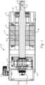
- an exemplary motor assembly is illustrated and identified generally by reference numeral 10. It will be appreciated that aspects of the present disclosure are applicable to a wide variety of electric motor configurations, as well as other applications where a rotating shaft is present (e.g., pumps, etc.). Accordingly, it should be understood that many of the features of the motor are exemplary in nature and intended to give context to certain aspects of the disclosure.
- the exemplary motor assembly 10 generally includes a housing 14 for supporting and/or enclosing the various internal components of the motor 10, as will be described below.
- the housing 14 includes a main tubular portion 15, a front bearing support/front plate 16 and rear bearing support 18, and an end cap 20. Together, these housing components form a sealed internal chamber (or multiple chambers) for housing, among other things, the rotating elements of the motor, related circuitry and a position feedback device.
- An electrical connector 21 provides a connection point for coupling the motor 10 to a motor drive (not shown).
- An output shaft 22 extends from the housing 14 for connection to an associated component to be driven by the motor assembly 10.
- the output shaft 22 in the illustrated embodiment includes a keyway 24 for receiving a key 26 for rotationally coupling the output shaft 22 to the associated component.
- Other coupling arrangements and/or devices are possible.
- the output shaft 22 is supported for rotation by front and rear bearings 30 and 32 which are supported, respectively, by the front bearing support/front plate 16 and the rear bearing support 18.
- a rotor 36 is fixed to the output shaft 22 for rotation therewith, while a stator 38 is fixed relative to the tubular main portion 15 of the housing 14.
- a position feedback device which in the illustrated embodiment is an encoder 42, is mounted to the rear bearing support 18. The encoder 42 is engaged with the output shaft 22 and provides feedback indicative of, among other things, the angular position of the output shaft 22.
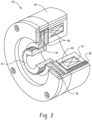
- the illustrated exemplary motor 10 further includes a brake assembly 44 for braking rotation of the output shaft 22.
- the brake assembly 44 is shown in partial cutaway view isolated from the motor assembly 10.
- the brake assembly 44 generally includes a brake housing 48 in which a coil 52 and a plurality of springs 56 are supported.
- An armature 60 associated with the coil 52 is configured to compress the springs 56 when energized.
- the springs 56 force the armature 60 against a brake rotor 64.
- the brake rotor 64 is splined to a brake hub 72, which in turn is fixed for rotation with the output shaft 22 of the motor assembly 10. Pressure from the springs 56 causes the armature 60 to clamp the brake rotor 64 against an end plate 76 thus braking the output shaft 22. Friction material 80 on the brake rotor 64 enhances the brake's holding ability.
- the brake assembly 44 is often referred to as a spring-set, fail-safe brake.
- the brake rotor 64 is designed to float on the brake hub 72 to allow for relatively axial movement therebetween during application and release of braking force. As such, a small tolerance in dimensions is maintained between the splines of the brake rotor 64 and the splines of the brake hub 72 to prevent binding. If the tolerance is too tight, the brake rotor 64 will bind on the brake hub 72 and fail to fully release from the end plate resulting in brake drag and/or premature brake failure.
- a new or unworn brake assembly typically has a minimal amount of backlash between the brake rotor 64 and brake hub 72.
- Backlash is a well-known concept in the field of mechanical engineering, but for the purposes of this disclosure backlash can broadly be understood to correspond to the amount of rotational play between the brake rotor 64 and the brake hub 72. As noted, some backlash may be present in a new or unworn brake, but excessive backlash can be problematic. Backlash tends to increase over time through wearing of the surfaces of the splines on one or both of the brake rotor 64 and brake hub 72.
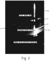
- FIGURE 3 illustrates a brake rotor/brake hub assembly with excessive backlash as indicated by arrow A. It should be appreciated that in the illustrated example, the softer metal (aluminum) of the brake hub 64 has worn considerably against the harder metal (steel) of the brake hub 72 resulting in the excessive backlash.
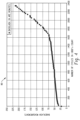
- FIGURE 4 illustrates a graph 80of cycles vs. backlash (in arc minutes). As can be seen, until about 1700000 cycles, backlash increases relatively steadily. After about 1700000 cycles, backlash increases at a much higher rate. The increased rate is due at least in part to a change in spline geometry. That is, at a certain point the geometry of the splines is worn substantially enough that further cycling causes rapid additional wear.
- aspects of the present disclosure are directed to monitoring the backlash such that corrective action can be taken prior to or within a period of time after reaching the inflection point of brake wear (e.g., 1700000 cycles in the case of the brake assembly of FIGURE 4 ).
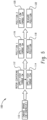
- a flowchart is shown illustrating a method 100 for measuring motor brake health.
- the method includes applying the brake assembly to hold the brake rotor in place (e.g., deenergizing the coil to restrict rotation of the brake rotor), centering the brake rotor (e.g., applying high torque to the drive shaft in both clockwise and counterclockwise directions), and applying a low torque to the drive shaft in the clockwise and counterclockwise and obtaining rotational position data from the encoder to determine the amount of play between the brake rotor and the brake hub.
- the method 100 will be described in connection with the motor assembly 10 shown in FIGS. 1 and 2 , but it should be appreciated that the method can be implemented on a wide variety of motor assemblies when such motor assemblies are properly configured to allow torqueing of the motor with the brake engaged.
- the method 100 begins in process step 110 wherein the brake assembly 44 of the motor assembly 10 is engaged. As noted above, this is typically performed by de-energizing the coil 52 of the brake assembly 44. In some motor circuitry or drive logic, the brake assembly is configured to be energized (brake disengaged) anytime the motor assembly is generating torque at the output shaft. However, the motor assembly 10 in accordance with the present disclosure is capable of de-energizing the brake assembly 44 (brake engaged) at the same time the motor assembly is generating torque at the output shaft, for example, when operated in a brake diagnostic mode.
- the motor assembly generates a relatively high torque (e.g., a centering torque) on the output shaft 22 in both the clockwise and counterclockwise rotational directions to center the brake rotor 64 and/or otherwise ensure the brake rotor 64 is freely floating on the brake hub 72.
- a relatively high torque e.g., a centering torque
- This step essentially shakes or jars the brake assembly to ensure that the rotor is free from interference due to, for example, brake dust particles or other foreign materials. If the brake rotor 64 is not centered and/or freely floating on the brake hub 72, the remaining steps may not produce a reliable measurement of brake backlash.
- a relatively low torque which is a backlash measuring torque is applied by the motor in a clockwise direction.
- the output shaft 22 and brake hub 72 may rotate relative to the brake rotor 64 until such time as any clearance between a first side of the splines of the brake hub 72 and a first side of the splines of the brake rotor 64 engage.
- An angular position of the output shaft is then recorded using the encoder 42 in process step 118.
- a relatively low torque is applied by the motor in a counter-clockwise direction.
- the output shaft 22 and brake 72 may rotate relative to the brake rotor 64 until such time as any clearance between a second side of the splines of the brake hub 72 and a second side of the splines of the brake rotor 64 engage.
- An angular position of the output shaft 22 is then recorded in process step 122. The difference between the angular positions recorded in process steps 118 and 122 is the brake backlash.
- the low torque (e.g., backlash measuring torque) applied by the motor is less than 50% of the continuous rated motor torque value
- the high torque (e.g., centering torque) applied by the motor is more than 50% of the continuous rated motor torque value, and possibly between 80-100% of the continuous rated motor torque value.
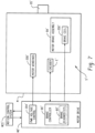
- FIGURE 6 is a block diagram showing a servo motor brake health monitoring and diagnostic system S according to an embodiment of the present disclosure.
- the motor M is operably connected to an electronic motion control system MCS such as an industrial automation control system or other electronic control system or processor.
- the motion control system MCS is operably connected to a motor drive MD which comprises electronic circuitry for controlling the motor M and brake assembly BA thereof in response to control inputs received from the motion control system MCS.
- the motor M includes an onboard motor controller MC that is part of the motor M, itself, and that is operably connected to the motor drive MD via connector C.
- the motor controller MC comprises one or more processing units, ASICS, and/or other electronic circuits for controlling the motor M in response to input commands received from the motor drive MD including input commands that specify a desired angular position for the output shaft OS and a speed at which the output shaft OS is to rotate.
- the motor controller MC selectively energizes the motor windings 200 of a stator to drive a rotor (not shown) in clockwise or counterclockwise directions using pulse width modulation (PWM) voltage signals 202 output by a PWM voltage control module 204 of the onboard motor controller MC.
- PWM pulse width modulation
- the onboard motor controller MC receives feedback or error signals 206 from the encoder E indicating the actual angular position of the rotor and output shaft OS, and the onboard motor controller MC continuously alters the PWN voltage signals 202 in response to the feedback received from the encoder E to reduce the error to zero at which time the output shaft OS is located in the specified angular position input by the motor drive MD.
- the onboard motor controller MC further comprises a brake controller BC as a part thereof.
- the brake controller BC comprises one or more electronic circuits for receiving input from the motor drive MD and motor controller MC as to the desired state of the brake assembly BA (i.e., brake engaged / "on” or brake disengaged / "off"), and the brake controller BC either energizes or de-energizes the brake electromagnetic coil 250 to control the brake assembly BA accordingly as generally described, using a coil control voltage signal 210 such as a pulse width modulation (PWM) voltage signal.
- PWM pulse width modulation
- the brake controller BC includes a brake diagnostics module BD that is configured to, among other things, measure the brake backlash in accordance with the method described in connection with FIGURE 5 .
- the brake diagnostics module BD is capable of simultaneously 1) de-energizing the brake coil 250 to engage the brake assembly BA and 2) energizing the motor winding 200 to apply torque to the output shaft of the motor at various levels and in both the clockwise and counterclockwise rotational directions.
- FIGURE 6 illustrates but one of many possible motor assemblies that can utilize aspects of the present disclosure.
- FIGURE 7 illustrates another exemplary servo motor brake health monitoring and diagnostic system S' similar in many respects to system S of FIGURE 6 with like components denoted with a single prime (e.g., MCS', M', MD', BC', BD', E', BA', 200', 204', 250').
- the system S' is virtually identical to the system S except that the motor M' does not include the onboard motor controller MC.
- the motor drive MD' performs all motor control operations and includes the PWM voltage controller 204' and the brake controller BC' with brake diagnostics BD', while the encoder E' provides feedback to the motor drive MD' for carrying out, among other things, the brake diagnostics routines set forth above.
- the present disclosure sets forth a method and apparatus for measuring brake backlash using the motor assembly's own position feedback device 42. This enables frequent tracking of brake wear such that the brake can be serviced prior to failure. The information obtained from frequent tracking of brake wear can be used to anticipate brake failure, or to generate an alert that service is required.
Landscapes
- Engineering & Computer Science (AREA)
- Power Engineering (AREA)
- Physics & Mathematics (AREA)
- General Physics & Mathematics (AREA)
- Braking Arrangements (AREA)
- Connection Of Motors, Electrical Generators, Mechanical Devices, And The Like (AREA)
Claims (11)
- Ein Verfahren zum Messen des Zustands der Motorbremse einer Motorbaugruppe (10) mit einer Bremsbaugruppe (44) zum Bremsen einer Abtriebswelle (22) des Motors und einer Positionsrücckopplungsvorrichtung (42) zum Messen einer Winkelposition der Abtriebswelle, wobei das Verfahren umfasst:Einrücken (110) der Bremsbaugruppe, um die Drehung eines Bremsrotors (64) der Bremsbaugruppe zu begrenzen, wobei der Bremsrotor (64) mit einer Bremsnabe (72) verkeilt ist, die für eine Drehung mit der Abtriebswelle (22) der Motorbaugruppe (10) befestigt ist;Zentrieren (112, 114) des Bremsrotors, wobei das Zentrieren des Bremsrotors das Erregen der Motorbaugruppe, um ein Zentrierdrehmoment auf der Abtriebswelle in einer ersten Drehrichtung aufzubringen, und das Erregen der Motorbaugruppe, um ein Zentrierdrehmomentniveau auf die Abtriebswelle in einer zweiten Drehrichtung aufzubringen, umfasst;Erregen (116) der Motorbaugruppe, um ein Spielmessdrehmomentniveau auf die Abtriebswelle der Motorbaugruppe in einer ersten Richtung aufzubringen, während die Bremsbaugruppe eingerückt ist, wobei sich die Abtriebswelle und die Bremsnabe relativ zum Bremsrotor drehen, bis ein Spiel zwischen einer ersten Seite der Keilnuten der Bremsnabe und einer ersten Seite der Keilnuten des Bremsrotors in Eingriff kommen, und wobei bei eingerückter Bremsbaugruppe eine weitere Drehung der Abtriebswelle (22) und einer Bremsnabe (72) verhindert wird;Messen (118) einer ersten Winkelposition der Abtriebswelle mit der Positionsrückmeldevorrichtung, während das Spielmessdrehmomentniveau angelegt wird;die Motorbaugruppe mit Energie versorgt wird (120), um ein Spielmessdrehmomentniveau auf die Abtriebswelle in einer zweiten Richtung aufzubringen, während die Bremsbaugruppe eingerückt ist; undeine zweite Winkelposition der Abtriebswelle mit der Positionsrückkopplungsvorrichtung gemessen wird (122), während das Spielmessdrehmomentniveau aufgebracht wird;wobei die Differenz zwischen der ersten Winkelposition und der zweiten Winkelposition einem Spielbetrag zwischen dem Bremsrotor und einer Bremsnabe der Bremsbaugruppe entspricht.
- Das Verfahren nach Anspruch 1, wobei mindestens eines der folgenden:das Einrücken der Bremse durch eine bordeigene Motorsteuerung der Motorbaugruppe durchgeführt wird; unddas Erregen der Motorbaugruppe, um ein Spielmessdrehmomentniveau auf die Abtriebswelle in der ersten oder zweiten Richtung aufzubringen, durch eine bordeigene Motorsteuerung durchgeführt wird, während die Bremse eingerückt ist.
- Das Verfahren nach Anspruch 1, wobei das Zentrierdrehmomentniveau größer als das SpielMessdrehmomentniveau ist.
- Ein Motorsystem (10), das eine Elektromotoreinheit mit einer Positionsrückkopplungsvorrichtung (42) und eine Bremseinheit (44) umfasst, wobei der Elektromotor einen Stator (38), einen Rotor (36) und eine Abtriebswelle (22) umfasst, die so konfiguriert ist, dass sie durch den Rotor angetrieben wird, wobei die Bremseinheit mit der Abtriebswelle wirkverbunden ist, um die Drehung der Abtriebswelle zu bremsen, wobei die Bremsenbaugruppe eine Bremsnabe (72), die an der Abtriebswelle befestigt ist, um sich mit dieser zu drehen, und einen Bremsrotor (64) umfasst, der drehbar mit der Bremsnabe verbunden ist, wobei die Positionsrückkopplungsvorrichtung (42) so konfiguriert ist, dass sie eine Winkelposition der Abtriebswelle misst, und eine Motorsteuerung, die operativ mit dem Elektromotor und der Bremsenbaugruppe verbunden ist, wobei die Motorsteuerung ein Bremsendiagnosemodul umfasst, das so konfiguriert ist, dass es:die Bremsenbaugruppe in Eingriff zu bringen (110), um die Drehung des Bremsrotors zu beschränken, wobei der Bremsrotor (64) mit der Bremsnabe (72) verkeilt ist, die für eine Drehung mit der Abtriebswelle (22) des Motorsystems (10) befestigt ist;Zentrieren (112, 114) des Bremsrotors, wobei das Zentrieren des Bremsrotors das Erregen der Motorbaugruppe, um ein Zentrierdrehmoment auf die Abtriebswelle in einer ersten Drehrichtung aufzubringen, und das Erregen der Motorbaugruppe, um ein Zentrierdrehmomentniveau auf die Abtriebswelle in einer zweiten Drehrichtung aufzubringen, umfasst;den Elektromotor (116) mit Strom versorgen, um ein Spielmessdrehmomentniveau auf die Abtriebswelle der Motorbaugruppe in einer ersten Richtung aufzubringen, während die Bremsbaugruppe eingerückt ist, wobei sich die Abtriebswelle und die Bremsnabe relativ zum Bremsrotor drehen, bis ein Spiel zwischen einer ersten Seite der Keilnuten der Bremsnabe und einer ersten Seite der Keilnuten des Bremsrotors in Eingriff kommen, und wobei bei eingerückter Bremsbaugruppe eine weitere Drehung der Abtriebswelle (22) und einer Bremsnabe (72) verhindert wird;Messen (118) einer ersten Winkelposition der Abtriebswelle mit der Positionsrückmeldevorrichtung, während das Spielmessdrehmomentniveau angelegt wird;die Motorbaugruppe mit Energie versorgen (120), um ein Spielmessdrehmomentniveau auf die Abtriebswelle in einer zweiten Richtung aufzubringen, während die Bremsbaugruppe eingerückt ist; undeine zweite Winkelposition der Abtriebswelle mit der Positionsrückkopplungsvorrichtung messen (122), während das Spielmessdrehmomentniveau aufgebracht wird;wobei die Differenz zwischen der ersten Winkelposition und der zweiten Winkelposition einem Spiel zwischen dem Bremsrotor und einer Bremsnabe der Bremsbaugruppe entspricht.
- Die Motorbaugruppe nach Anspruch 4, wobei der Elektromotor ein Servomotor ist.
- Die Motorbaugruppe nach Anspruch 4 oder 5, wobei die Bremsbaugruppe eine Spule und mindestens eine Feder zum Vorspannen eines Ankers der Spule in Richtung einer Bremsbetätigungsposition umfasst, wobei die Spule so konfiguriert ist, dass sie die Bremse löst, wenn sie durch die Bordsteuerung erregt wird.
- Die Motorbaugruppe nach Anspruch 6, wobei der Bremsrotor und die Bremsnabe ineinandergreifende Keilnuten aufweisen, wobei der Bremsrotor während des Ein- und Ausrückens der Bremse axial relativ zum Bremsrotor beweglich ist.
- Die Motorbaugruppe nach Anspruch 7, wobei die Keilnuten einen trapezförmigen Querschnitt aufweisen.
- Die Motorbaugruppe nach Anspruch 6, wobei
das Zentrierdrehmomentniveau größer als das Spielmessdrehmomentniveau ist. - Ein Motorantrieb für eine Motorbaugruppe (10) mit einem Elektromotor mit einer Abtriebswelle (22), einer Bremsbaugruppe (44) zum Abbremsen der Drehung der Abtriebswelle und einer Positionsrückkopplungsvorrichtung (42), wobei der Motorantrieb eine Bremssteuerung mit Bremsendiagnose umfasst und der Motorantrieb so konfiguriert ist, dass erdie Bremsbaugruppe zu betätigen (110), um die Drehung eines Bremsrotors der Bremsbaugruppe zu begrenzen, wobei der Bremsrotor (64) mit einer Bremsnabe (72) verkeilt ist, die für eine Drehung mit der Abtriebswelle (22) der Motorbaugruppe (10) befestigt ist;Zentrieren (112, 114) des Bremsrotors, wobei das Zentrieren des Bremsrotors das Erregen der Motorbaugruppe umfasst, um ein Zentrierdrehmoment auf die Abtriebswelle in einer ersten Drehrichtung aufzubringen, und das Erregen der Motorbaugruppe, um ein Zentrierdrehmomentniveau auf die Abtriebswelle in einer zweiten Drehrichtung aufzubringen;den Elektromotor (116) mit Strom versorgen, um ein Spielmessdrehmomentniveau auf die Abtriebswelle in einer ersten Richtung aufzubringen, während die Bremsbaugruppe eingerückt ist, wobei sich die Abtriebswelle und die Bremsnabe relativ zum Bremsrotor drehen, bis ein Spiel zwischen einer ersten Seite der Keilnuten der Bremsnabe und einer ersten Seite der Keilnuten des Bremsrotors in Eingriff kommen, und wobei bei eingerückter Bremsbaugruppe eine weitere Drehung der Abtriebswelle (22) und einer Bremsnabe (72) verhindert wird;Messen (118) einer ersten Winkelposition der Abtriebswelle mit der Positionsrückmeldevorrichtung, während das Spielmessdrehmomentniveau angelegt wird;Erregen (120) des Elektromotors, um ein Spielmessdrehmomentniveau an die Abtriebswelle in einer zweiten Richtung anzulegen, während die Bremsanordnung eingerückt ist; undeine zweite Winkelposition der Abtriebswelle mit der Positionsrückmeldevorrichtung messen (122), während das Spielmessdrehmomentniveau angelegt wird;wobei die Differenz zwischen der ersten Winkelposition und der zweiten Winkelposition einem Spielbetrag zwischen dem Bremsrotor und einer Bremsnabe der Bremsenbaugruppe entspricht.
- Der Motorantrieb nach Anspruch 10, wobei
das Zentrierdrehmomentniveau größer als das Spielmessdrehmomentniveau ist.
Applications Claiming Priority (1)
| Application Number | Priority Date | Filing Date | Title |
|---|---|---|---|
| US15/717,117 US10663365B2 (en) | 2017-09-27 | 2017-09-27 | Method for measuring motor brake health |
Publications (2)
| Publication Number | Publication Date |
|---|---|
| EP3462596A1 EP3462596A1 (de) | 2019-04-03 |
| EP3462596B1 true EP3462596B1 (de) | 2024-12-11 |
Family
ID=63685858
Family Applications (1)
| Application Number | Title | Priority Date | Filing Date |
|---|---|---|---|
| EP18197160.7A Active EP3462596B1 (de) | 2017-09-27 | 2018-09-27 | Verfahren zur messung des zustands der motorbremse |
Country Status (2)
| Country | Link |
|---|---|
| US (1) | US10663365B2 (de) |
| EP (1) | EP3462596B1 (de) |
Families Citing this family (2)
| Publication number | Priority date | Publication date | Assignee | Title |
|---|---|---|---|---|
| CN112964481B (zh) * | 2021-02-26 | 2023-06-20 | 蜂巢传动科技河北有限公司 | At变速器的制动器的检测机构和检测装置 |
| CN113657693B (zh) * | 2021-10-20 | 2022-02-08 | 中国电子产品可靠性与环境试验研究所((工业和信息化部电子第五研究所)(中国赛宝实验室)) | 一种智能制造装备的预测性维护系统和方法 |
Citations (1)
| Publication number | Priority date | Publication date | Assignee | Title |
|---|---|---|---|---|
| WO2017089652A1 (en) * | 2015-11-25 | 2017-06-01 | Konecranes Global Corporation | Brake condition monitoring |
Family Cites Families (17)
| Publication number | Priority date | Publication date | Assignee | Title |
|---|---|---|---|---|
| HU167207B (de) * | 1972-05-17 | 1975-09-27 | ||
| US5785158A (en) * | 1996-02-01 | 1998-07-28 | Sundstrand Corporation | Brake apparatus with functional integrity monitor |
| DE29611732U1 (de) | 1996-07-05 | 1996-09-05 | Chr. Mayr Gmbh + Co Kg, 87665 Mauerstetten | Elektromagnetisch gelüftete Reibungs-Sicherheitsbremse mit zwei Bremsscheiben und einem axial verschieblichen unverdrehbaren Elektromagneten |
| JP4427866B2 (ja) * | 1999-12-17 | 2010-03-10 | アイシン・エィ・ダブリュ株式会社 | モータ |
| DE10127664C1 (de) | 2001-06-07 | 2003-04-17 | Kendrion Binder Magnete Gmbh | Elektromagnetisch betätigbare Bremsvorrichtung |
| US20050241894A1 (en) * | 2002-02-13 | 2005-11-03 | Johann Baumgartner | Disc brake with an electric motor driven adjustment device and method for controlling a disk brake |
| US20040124046A1 (en) * | 2002-12-30 | 2004-07-01 | Hayes Brian David | Separable brake rotor |
| US7466100B2 (en) * | 2004-01-21 | 2008-12-16 | Peaktronics, Inc. | Digital high-resolution controller |
| JP4512868B2 (ja) * | 2004-03-31 | 2010-07-28 | 日立オートモティブシステムズ株式会社 | 電動ブレーキ装置 |
| US7295907B2 (en) * | 2005-06-14 | 2007-11-13 | Trw Automotive U.S. Llc | Recovery of calibrated center steering position after loss of battery power |
| DE102006032992A1 (de) * | 2006-07-17 | 2008-01-31 | Siemens Ag | Rotor für eine elektrische Maschine sowie elektrische Maschine mit einem derartigen Rotor |
| DE102009018559A1 (de) | 2009-04-24 | 2010-10-28 | Kendrion Linnig Gmbh | Verfahren zur Herstellung von Kupplungs- und Bremsscheiben für Elektromagnetkupplungen oder Elektromagnetbremsen mit mindestens einem Reibflächenelement |
| DE102012108672B3 (de) * | 2012-09-17 | 2014-02-06 | Knorr-Bremse Systeme für Nutzfahrzeuge GmbH | Nachstelleinrichtung einer Scheibenbremse, eine entsprechende Scheibenbremse und Verfahren zum Betreiben einer Verschleißnachstellvorrichtung einer Scheibenbremse |
| CN104329221B (zh) | 2014-09-04 | 2017-02-15 | 成都阜特科技股份有限公司 | 一种变桨距系统的收桨方法 |
| EP3023846A1 (de) | 2014-11-18 | 2016-05-25 | Moog Unna GmbH | Elektromechanisches Antriebssystem |
| CA3013036C (en) * | 2016-01-29 | 2023-01-03 | Magnetek, Inc. | Method and apparatus for controlling motion in a counterbalancing system |
| US20190063524A1 (en) * | 2017-08-25 | 2019-02-28 | Benjamin V. Booher | Motor vehicle brake rotor speed reduction mechanism |
-
2017
- 2017-09-27 US US15/717,117 patent/US10663365B2/en active Active
-
2018
- 2018-09-27 EP EP18197160.7A patent/EP3462596B1/de active Active
Patent Citations (1)
| Publication number | Priority date | Publication date | Assignee | Title |
|---|---|---|---|---|
| WO2017089652A1 (en) * | 2015-11-25 | 2017-06-01 | Konecranes Global Corporation | Brake condition monitoring |
Also Published As
| Publication number | Publication date |
|---|---|
| US20190094091A1 (en) | 2019-03-28 |
| US10663365B2 (en) | 2020-05-26 |
| EP3462596A1 (de) | 2019-04-03 |
Similar Documents
| Publication | Publication Date | Title |
|---|---|---|
| US10520054B2 (en) | Motor brake system | |
| JP5072370B2 (ja) | インホイールモータ駆動装置 | |
| US7712588B2 (en) | Temperature based clearance control for vehicle brake | |
| US10113601B2 (en) | Electric brake device | |
| EP3462596B1 (de) | Verfahren zur messung des zustands der motorbremse | |
| US11292442B2 (en) | Electromechanical brake system | |
| CN101419106A (zh) | 基于差速拧紧的装载机主锥预紧力测量装置和方法 | |
| JP4991164B2 (ja) | 電気ブレーキを備えたブレーキシステムにおけるサーボコントロールの方法 | |
| CN109477462B (zh) | 风车驱动系统和风车 | |
| KR102577400B1 (ko) | 패스너가 이미 조여졌는지를 검출하는 방법 | |
| JP2007516852A (ja) | 流体力インパルスレンチ及び動力ねじジョイント締付け工具システムの動作調整方法 | |
| WO2018008754A1 (ja) | 風車駆動システム及び風車 | |
| US20170343070A1 (en) | Electric Actuator for S-Cam Brake | |
| JP2016151509A (ja) | モータトルク測定装置及びモータトルク測定方法 | |
| EP3006284B1 (de) | Elektrisches bremssteuerungssystem | |
| CN115009250A (zh) | 轨道车辆电子机械制动系统闸片磨损检测方法及系统 | |
| TW202334627A (zh) | 動平衡監控系統及其監控方法 | |
| US11454948B2 (en) | Method for analyzing the status of an electromechanical joining system and electromechanical joining system for carrying out the method | |
| JP2015129584A (ja) | 車両駆動系トルク管理プロセス | |
| US5785158A (en) | Brake apparatus with functional integrity monitor | |
| US6913327B2 (en) | Method and apparatus for control of a motor-driven brake actuator | |
| WO2012164238A2 (en) | Method and apparatus for torque control of an electrical machine | |
| CN113443001B (zh) | 提高蜗轮耐久性的可变行程停止件 | |
| US10704661B2 (en) | Actuator device having cam and follower and controller configured to employ rate-based methodology to identify positioning of follower on cam at predetermined location | |
| CN104096917B (zh) | 一种齿轮加工设备 |
Legal Events
| Date | Code | Title | Description |
|---|---|---|---|
| PUAI | Public reference made under article 153(3) epc to a published international application that has entered the european phase |
Free format text: ORIGINAL CODE: 0009012 |
|
| STAA | Information on the status of an ep patent application or granted ep patent |
Free format text: STATUS: THE APPLICATION HAS BEEN PUBLISHED |
|
| AK | Designated contracting states |
Kind code of ref document: A1 Designated state(s): AL AT BE BG CH CY CZ DE DK EE ES FI FR GB GR HR HU IE IS IT LI LT LU LV MC MK MT NL NO PL PT RO RS SE SI SK SM TR |
|
| AX | Request for extension of the european patent |
Extension state: BA ME |
|
| STAA | Information on the status of an ep patent application or granted ep patent |
Free format text: STATUS: REQUEST FOR EXAMINATION WAS MADE |
|
| TPAC | Observations filed by third parties |
Free format text: ORIGINAL CODE: EPIDOSNTIPA |
|
| 17P | Request for examination filed |
Effective date: 20190905 |
|
| RBV | Designated contracting states (corrected) |
Designated state(s): AL AT BE BG CH CY CZ DE DK EE ES FI FR GB GR HR HU IE IS IT LI LT LU LV MC MK MT NL NO PL PT RO RS SE SI SK SM TR |
|
| STAA | Information on the status of an ep patent application or granted ep patent |
Free format text: STATUS: EXAMINATION IS IN PROGRESS |
|
| 17Q | First examination report despatched |
Effective date: 20200305 |
|
| GRAP | Despatch of communication of intention to grant a patent |
Free format text: ORIGINAL CODE: EPIDOSNIGR1 |
|
| STAA | Information on the status of an ep patent application or granted ep patent |
Free format text: STATUS: GRANT OF PATENT IS INTENDED |
|
| RIC1 | Information provided on ipc code assigned before grant |
Ipc: F16D 66/00 20060101ALN20240621BHEP Ipc: H02P 1/16 20060101ALI20240621BHEP Ipc: F16D 63/00 20060101ALI20240621BHEP Ipc: H02P 3/04 20060101AFI20240621BHEP |
|
| INTG | Intention to grant announced |
Effective date: 20240712 |
|
| GRAS | Grant fee paid |
Free format text: ORIGINAL CODE: EPIDOSNIGR3 |
|
| GRAA | (expected) grant |
Free format text: ORIGINAL CODE: 0009210 |
|
| STAA | Information on the status of an ep patent application or granted ep patent |
Free format text: STATUS: THE PATENT HAS BEEN GRANTED |
|
| AK | Designated contracting states |
Kind code of ref document: B1 Designated state(s): AL AT BE BG CH CY CZ DE DK EE ES FI FR GB GR HR HU IE IS IT LI LT LU LV MC MK MT NL NO PL PT RO RS SE SI SK SM TR |
|
| REG | Reference to a national code |
Ref country code: GB Ref legal event code: FG4D |
|
| REG | Reference to a national code |
Ref country code: CH Ref legal event code: EP |
|
| REG | Reference to a national code |
Ref country code: IE Ref legal event code: FG4D |
|
| REG | Reference to a national code |
Ref country code: DE Ref legal event code: R096 Ref document number: 602018077458 Country of ref document: DE |
|
| REG | Reference to a national code |
Ref country code: LT Ref legal event code: MG9D |
|
| PG25 | Lapsed in a contracting state [announced via postgrant information from national office to epo] |
Ref country code: HR Free format text: LAPSE BECAUSE OF FAILURE TO SUBMIT A TRANSLATION OF THE DESCRIPTION OR TO PAY THE FEE WITHIN THE PRESCRIBED TIME-LIMIT Effective date: 20241211 |
|
| PG25 | Lapsed in a contracting state [announced via postgrant information from national office to epo] |
Ref country code: FI Free format text: LAPSE BECAUSE OF FAILURE TO SUBMIT A TRANSLATION OF THE DESCRIPTION OR TO PAY THE FEE WITHIN THE PRESCRIBED TIME-LIMIT Effective date: 20241211 |
|
| PG25 | Lapsed in a contracting state [announced via postgrant information from national office to epo] |
Ref country code: BG Free format text: LAPSE BECAUSE OF FAILURE TO SUBMIT A TRANSLATION OF THE DESCRIPTION OR TO PAY THE FEE WITHIN THE PRESCRIBED TIME-LIMIT Effective date: 20241211 |
|
| REG | Reference to a national code |
Ref country code: NL Ref legal event code: MP Effective date: 20241211 |
|
| PG25 | Lapsed in a contracting state [announced via postgrant information from national office to epo] |
Ref country code: ES Free format text: LAPSE BECAUSE OF FAILURE TO SUBMIT A TRANSLATION OF THE DESCRIPTION OR TO PAY THE FEE WITHIN THE PRESCRIBED TIME-LIMIT Effective date: 20241211 |
|
| PG25 | Lapsed in a contracting state [announced via postgrant information from national office to epo] |
Ref country code: NO Free format text: LAPSE BECAUSE OF FAILURE TO SUBMIT A TRANSLATION OF THE DESCRIPTION OR TO PAY THE FEE WITHIN THE PRESCRIBED TIME-LIMIT Effective date: 20250311 |
|
| PG25 | Lapsed in a contracting state [announced via postgrant information from national office to epo] |
Ref country code: LV Free format text: LAPSE BECAUSE OF FAILURE TO SUBMIT A TRANSLATION OF THE DESCRIPTION OR TO PAY THE FEE WITHIN THE PRESCRIBED TIME-LIMIT Effective date: 20241211 Ref country code: GR Free format text: LAPSE BECAUSE OF FAILURE TO SUBMIT A TRANSLATION OF THE DESCRIPTION OR TO PAY THE FEE WITHIN THE PRESCRIBED TIME-LIMIT Effective date: 20250312 |
|
| PG25 | Lapsed in a contracting state [announced via postgrant information from national office to epo] |
Ref country code: RS Free format text: LAPSE BECAUSE OF FAILURE TO SUBMIT A TRANSLATION OF THE DESCRIPTION OR TO PAY THE FEE WITHIN THE PRESCRIBED TIME-LIMIT Effective date: 20250311 |
|
| PG25 | Lapsed in a contracting state [announced via postgrant information from national office to epo] |
Ref country code: NL Free format text: LAPSE BECAUSE OF FAILURE TO SUBMIT A TRANSLATION OF THE DESCRIPTION OR TO PAY THE FEE WITHIN THE PRESCRIBED TIME-LIMIT Effective date: 20241211 |
|
| REG | Reference to a national code |
Ref country code: AT Ref legal event code: MK05 Ref document number: 1751163 Country of ref document: AT Kind code of ref document: T Effective date: 20241211 |
|
| PG25 | Lapsed in a contracting state [announced via postgrant information from national office to epo] |
Ref country code: SM Free format text: LAPSE BECAUSE OF FAILURE TO SUBMIT A TRANSLATION OF THE DESCRIPTION OR TO PAY THE FEE WITHIN THE PRESCRIBED TIME-LIMIT Effective date: 20241211 |
|
| PG25 | Lapsed in a contracting state [announced via postgrant information from national office to epo] |
Ref country code: PL Free format text: LAPSE BECAUSE OF FAILURE TO SUBMIT A TRANSLATION OF THE DESCRIPTION OR TO PAY THE FEE WITHIN THE PRESCRIBED TIME-LIMIT Effective date: 20241211 |
|
| PG25 | Lapsed in a contracting state [announced via postgrant information from national office to epo] |
Ref country code: IS Free format text: LAPSE BECAUSE OF FAILURE TO SUBMIT A TRANSLATION OF THE DESCRIPTION OR TO PAY THE FEE WITHIN THE PRESCRIBED TIME-LIMIT Effective date: 20250411 |
|
| PG25 | Lapsed in a contracting state [announced via postgrant information from national office to epo] |
Ref country code: PT Free format text: LAPSE BECAUSE OF FAILURE TO SUBMIT A TRANSLATION OF THE DESCRIPTION OR TO PAY THE FEE WITHIN THE PRESCRIBED TIME-LIMIT Effective date: 20250411 |
|
| PG25 | Lapsed in a contracting state [announced via postgrant information from national office to epo] |
Ref country code: EE Free format text: LAPSE BECAUSE OF FAILURE TO SUBMIT A TRANSLATION OF THE DESCRIPTION OR TO PAY THE FEE WITHIN THE PRESCRIBED TIME-LIMIT Effective date: 20241211 |
|
| PG25 | Lapsed in a contracting state [announced via postgrant information from national office to epo] |
Ref country code: AT Free format text: LAPSE BECAUSE OF FAILURE TO SUBMIT A TRANSLATION OF THE DESCRIPTION OR TO PAY THE FEE WITHIN THE PRESCRIBED TIME-LIMIT Effective date: 20241211 Ref country code: RO Free format text: LAPSE BECAUSE OF FAILURE TO SUBMIT A TRANSLATION OF THE DESCRIPTION OR TO PAY THE FEE WITHIN THE PRESCRIBED TIME-LIMIT Effective date: 20241211 |
|
| PG25 | Lapsed in a contracting state [announced via postgrant information from national office to epo] |
Ref country code: SK Free format text: LAPSE BECAUSE OF FAILURE TO SUBMIT A TRANSLATION OF THE DESCRIPTION OR TO PAY THE FEE WITHIN THE PRESCRIBED TIME-LIMIT Effective date: 20241211 |
|
| PG25 | Lapsed in a contracting state [announced via postgrant information from national office to epo] |
Ref country code: CZ Free format text: LAPSE BECAUSE OF FAILURE TO SUBMIT A TRANSLATION OF THE DESCRIPTION OR TO PAY THE FEE WITHIN THE PRESCRIBED TIME-LIMIT Effective date: 20241211 |
|
| PG25 | Lapsed in a contracting state [announced via postgrant information from national office to epo] |
Ref country code: IT Free format text: LAPSE BECAUSE OF FAILURE TO SUBMIT A TRANSLATION OF THE DESCRIPTION OR TO PAY THE FEE WITHIN THE PRESCRIBED TIME-LIMIT Effective date: 20241211 |
|
| PG25 | Lapsed in a contracting state [announced via postgrant information from national office to epo] |
Ref country code: SE Free format text: LAPSE BECAUSE OF FAILURE TO SUBMIT A TRANSLATION OF THE DESCRIPTION OR TO PAY THE FEE WITHIN THE PRESCRIBED TIME-LIMIT Effective date: 20241211 |
|
| REG | Reference to a national code |
Ref country code: DE Ref legal event code: R097 Ref document number: 602018077458 Country of ref document: DE |
|
| PG25 | Lapsed in a contracting state [announced via postgrant information from national office to epo] |
Ref country code: DK Free format text: LAPSE BECAUSE OF FAILURE TO SUBMIT A TRANSLATION OF THE DESCRIPTION OR TO PAY THE FEE WITHIN THE PRESCRIBED TIME-LIMIT Effective date: 20241211 |
|
| PGFP | Annual fee paid to national office [announced via postgrant information from national office to epo] |
Ref country code: DE Payment date: 20250820 Year of fee payment: 8 |
|
| PGFP | Annual fee paid to national office [announced via postgrant information from national office to epo] |
Ref country code: GB Payment date: 20250820 Year of fee payment: 8 |
|
| PLBE | No opposition filed within time limit |
Free format text: ORIGINAL CODE: 0009261 |
|
| STAA | Information on the status of an ep patent application or granted ep patent |
Free format text: STATUS: NO OPPOSITION FILED WITHIN TIME LIMIT |
|
| PGFP | Annual fee paid to national office [announced via postgrant information from national office to epo] |
Ref country code: FR Payment date: 20250820 Year of fee payment: 8 |
|
| 26N | No opposition filed |
Effective date: 20250912 |