EP3462131B1 - Scanning range setting method and survey system for the method - Google Patents
Scanning range setting method and survey system for the method Download PDFInfo
- Publication number
- EP3462131B1 EP3462131B1 EP18194575.9A EP18194575A EP3462131B1 EP 3462131 B1 EP3462131 B1 EP 3462131B1 EP 18194575 A EP18194575 A EP 18194575A EP 3462131 B1 EP3462131 B1 EP 3462131B1
- Authority
- EP
- European Patent Office
- Prior art keywords
- scanning range
- measurement points
- scanner
- scanning
- measurement
- Prior art date
- Legal status (The legal status is an assumption and is not a legal conclusion. Google has not performed a legal analysis and makes no representation as to the accuracy of the status listed.)
- Active
Links
Images


Classifications
-
- G—PHYSICS
- G01—MEASURING; TESTING
- G01C—MEASURING DISTANCES, LEVELS OR BEARINGS; SURVEYING; NAVIGATION; GYROSCOPIC INSTRUMENTS; PHOTOGRAMMETRY OR VIDEOGRAMMETRY
- G01C15/00—Surveying instruments or accessories not provided for in groups G01C1/00 - G01C13/00
- G01C15/002—Active optical surveying means
-
- G—PHYSICS
- G01—MEASURING; TESTING
- G01C—MEASURING DISTANCES, LEVELS OR BEARINGS; SURVEYING; NAVIGATION; GYROSCOPIC INSTRUMENTS; PHOTOGRAMMETRY OR VIDEOGRAMMETRY
- G01C11/00—Photogrammetry or videogrammetry, e.g. stereogrammetry; Photographic surveying
- G01C11/02—Picture taking arrangements specially adapted for photogrammetry or photographic surveying, e.g. controlling overlapping of pictures
- G01C11/025—Picture taking arrangements specially adapted for photogrammetry or photographic surveying, e.g. controlling overlapping of pictures by scanning the object
-
- G—PHYSICS
- G01—MEASURING; TESTING
- G01S—RADIO DIRECTION-FINDING; RADIO NAVIGATION; DETERMINING DISTANCE OR VELOCITY BY USE OF RADIO WAVES; LOCATING OR PRESENCE-DETECTING BY USE OF THE REFLECTION OR RERADIATION OF RADIO WAVES; ANALOGOUS ARRANGEMENTS USING OTHER WAVES
- G01S17/00—Systems using the reflection or reradiation of electromagnetic waves other than radio waves, e.g. lidar systems
- G01S17/02—Systems using the reflection of electromagnetic waves other than radio waves
- G01S17/06—Systems determining position data of a target
- G01S17/42—Simultaneous measurement of distance and other co-ordinates
-
- G—PHYSICS
- G01—MEASURING; TESTING
- G01S—RADIO DIRECTION-FINDING; RADIO NAVIGATION; DETERMINING DISTANCE OR VELOCITY BY USE OF RADIO WAVES; LOCATING OR PRESENCE-DETECTING BY USE OF THE REFLECTION OR RERADIATION OF RADIO WAVES; ANALOGOUS ARRANGEMENTS USING OTHER WAVES
- G01S17/00—Systems using the reflection or reradiation of electromagnetic waves other than radio waves, e.g. lidar systems
- G01S17/86—Combinations of lidar systems with systems other than lidar, radar or sonar, e.g. with direction finders
-
- G—PHYSICS
- G01—MEASURING; TESTING
- G01S—RADIO DIRECTION-FINDING; RADIO NAVIGATION; DETERMINING DISTANCE OR VELOCITY BY USE OF RADIO WAVES; LOCATING OR PRESENCE-DETECTING BY USE OF THE REFLECTION OR RERADIATION OF RADIO WAVES; ANALOGOUS ARRANGEMENTS USING OTHER WAVES
- G01S7/00—Details of systems according to groups G01S13/00, G01S15/00, G01S17/00
- G01S7/48—Details of systems according to groups G01S13/00, G01S15/00, G01S17/00 of systems according to group G01S17/00
- G01S7/481—Constructional features, e.g. arrangements of optical elements
- G01S7/4817—Constructional features, e.g. arrangements of optical elements relating to scanning
-
- G—PHYSICS
- G01—MEASURING; TESTING
- G01S—RADIO DIRECTION-FINDING; RADIO NAVIGATION; DETERMINING DISTANCE OR VELOCITY BY USE OF RADIO WAVES; LOCATING OR PRESENCE-DETECTING BY USE OF THE REFLECTION OR RERADIATION OF RADIO WAVES; ANALOGOUS ARRANGEMENTS USING OTHER WAVES
- G01S7/00—Details of systems according to groups G01S13/00, G01S15/00, G01S17/00
- G01S7/48—Details of systems according to groups G01S13/00, G01S15/00, G01S17/00 of systems according to group G01S17/00
- G01S7/51—Display arrangements
Definitions
- the present invention relates to a scanning range setting method of a laser scanner configured to acquire three-dimensional data of a survey site.
- a laser scanner As a device capable of measuring three-dimensional data of a survey site, a laser scanner is known.
- a laser scanner scans a pulsed laser over a set measurement area to acquire three-dimensional point group data of pulsed laser irradiation points (for example, JP 5057734 ).
- a scanning range is manually set by a person.
- setting of a scanning range of a laser scanner is difficult. If setting of a scanning range is incorrect, the scanning range is not associated with measured three-dimensional data, and a mismatch point will occur in a three-dimensional model.
- the inventor considered that by automatically setting a scanning range by using coordinate data of measurement points measured by a surveying instrument, setting of a scanning range could be easily and preferably performed, and proposed the present invention.
- an object of the present invention is to provide a scanning range setting method to enable easy and preferable setting of a scanning range, and a survey system for the method.
- a scanning range setting method is a scanning range setting method that uses a surveying instrument configured to measure a distance to a measurement point by using a distance measuring light and measure an angle to the measurement point, and a scanner configured to scan a scanning light around a rotation axis to acquire three-dimensional point group data, and includes steps of: (A) measuring a distance to two or more measurement points by the surveying instrument, (B) storing coordinates and angles of the measurement points, (C) setting an area including all of the measurement points as a scanning range by the scanner, and (D) scanning the scanning range by the scanner, wherein a coordinate system of the scanner and a coordinate system of the surveying instrument match each other.
- the scanning range setting method further include, in the step (C), a step (c) of setting the scanning range as an enlarged scanning range by enlarging the scanning range by a predetermined range.
- the scanning range setting method further include, after the step (D), a step (E) of merging coordinate data of the measurement points acquired by the surveying instrument and the three-dimensional point group data acquired by the scanner.
- the scanning range setting method further includes, after the step (C), a step of displaying the scanning range superimposed on a landscape image acquired by using a camera.
- a survey system includes a surveying instrument configured to measure a distance to two or more measurement points by using a distance measuring light and measure angles to the measurement points, and a scanner configured to scan a scanning light around a rotation axis to acquire three-dimensional point group data, wherein the scanner includes a data storage unit configured to store coordinates and angles of the measurement points, and is configured to, automatically set an area including all of the measurement points as a scanning range, based on the coordinates and angles of the measurement points stored.
- the survey system includes a camera configured to photograph a landscape image including the measurement points
- the surveying instrument include a display unit configured to display the coordinates of the measurement points and the landscape image
- the display unit is configured to display the scanning range by superimposing the scanning range on the landscape image.
- a scanning range can be easily and preferably set.
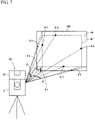
- FIG. 1 is a schematic view illustrating an external configuration of a survey system 1 according to a first embodiment of the present invention.
- the survey system 1 includes a surveying instrument 2 and a scanner 22.
- the surveying instrument 2 and the scanner 22 are integrated and have a mechanical positional relationship being known, and are configured so that their coordinate systems match each other.
- correction coefficients are set so that the coordinate systems match each other.
- the surveying instrument 2 is a so-called motor drive total station, and is installed at a known point by using a tripod.
- the surveying instrument 2 includes, in order from the lower side, a leveling section, a base section provided on the leveling section, a housing 2b that rotates around a horizontal rotation axis H-H on the base section, and a telescope 2a that rotates around a vertical rotation axis V-V at the center of the housing 2b.
- the reference signs 9-1, 9-2, 9-3, ..., 9-n denote measurement points at each of which a target (prism or reflection sheet) is set. In the following description, a measurement point whose position is not specified is designated by a reference sign 9-n.
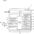
- FIG. 2 is a configuration block diagram of the survey system 1.
- the survey system 1 includes a horizontal angle detector 11, a vertical angle detector 12, a horizontal rotation drive unit 13, a vertical rotation drive unit 14, a display unit 15, an operation unit 16, an arithmetic control unit 17, a tracking unit 18, a distance measuring unit 19, a storage unit 20, a sound output unit 21, and a scanner 22.
- the horizontal rotation drive unit 13 and the vertical rotation drive unit 14 are motors, and are controlled by the arithmetic control unit 17 and respectively drive the rotation about the horizontal rotation axis H-H and the rotation about the vertical rotation axis V-V.
- a distance measuring light is emitted from the telescope 2a.
- the horizontal angle detector 11 and the vertical angle detector 12 are rotary encoders each including a rotary disk, slits, a light emitting diode, and an image sensor.
- the horizontal angle detector 11 is provided for the horizontal rotation axis H-H ( FIG. 1 ) and detects a rotation angle in the horizontal direction of the housing 2b.
- the vertical angle detector 12 is provided for the vertical rotation axis V-V ( FIG. 1 ) and detects a rotation angle in the vertical direction of the telescope 2a.
- the display unit 15 and the operation unit 16 are interfaces of the survey system 1. Via the display unit 15 and the operation unit 16, a user can perform a command and setting of a survey operation and confirmation of measurement results, etc., of the surveying instrument 2 and the scanner 22.
- the distance measuring unit 19 transmits an infrared pulsed laser light as a distance measuring light to a measurement point 9-n. Then, a reflected light from the measurement point 9-n is received by a light receiving unit, for example, a photodiode, etc., and converted into a distance measurement signal.
- the reference sign 4 in FIG. 1 denotes an optical axis of the distance measuring light.
- the tracking unit 18 transmits, as a tracking light, an infrared laser light with a wavelength different from that of the distance measuring light.
- a light receiving unit such as an image sensor
- a landscape image including the tracking light and a landscape image excluding the tracking light are acquired.
- the arithmetic control unit 17 detects a position of the measurement point 9-n from a difference between the images, and performs automatic tracking so that the telescope 2a always faces a direction of the measurement point 9-n.
- the arithmetic control unit 17 is, for example, a microcontroller including a CPU, a ROM, and a RAM, etc., mounted on an integrated circuit, and controls the rotation drive units 13 and 14, performs automatic tracking by the tracking unit 18, and performs automatic collimation by comparing outputs of distance measurement signals.
- the arithmetic control unit 17 measures a distance to each of the measurement points 9-1, 9-2, 9-3, ..., 9-n based on the number of light wave oscillations from light transmission to light reception, and from values detected by the horizontal angle detector 11 and the vertical angle detector 12, measures an angle to each of the measurement points 9-1, 9-2, 9-3, ..., 9-n, and measures an X coordinate, a Y coordinate, and a Z coordinate of each measurement point.
- the storage unit 20 is, for example, a hard disk drive. In the storage unit 20, a program for the arithmetic control described above is stored.
- the sound output unit 21 is a speaker, and outputs a sound based on a command from the arithmetic control unit 17.
- the scanner 22 is a three-dimensional laser scanner.
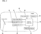
- FIG. 3 is a configuration block diagram of the scanner 22 according to the embodiment.
- the scanner 22 includes a vertical angle detector 31, a vertical rotation drive unit 32, a turning mirror 33, a communication unit 34, an arithmetic control unit 35, a storage unit 36, a distance measuring unit 37, and a data storage unit 39.
- the turning mirror 33 is driven by the vertical rotation drive unit 32 to turn around the vertical rotation axis R-R ( FIG. 1 ) via a lens barrel not illustrated.
- the turning mirror 33 is also disposed on the horizontal rotation axis H-H of the surveying instrument 2 via a housing 22a ( FIG. 1 ) of the scanner 22, and the housing 22a of the scanner 22 and the housing 2b of the surveying instrument 2 integrally rotate horizontally.
- the distance measuring unit 37 scans vertically an infrared pulsed laser light as a scanning light toward a measuring target by using the turning mirror 33. Then, a reflected light of the infrared pulsed laser light is received by a light receiving unit, for example, a photodiode, etc.
- the reference sign 5 in FIG. 1 denotes an optical axis of a scanning light of the scanner 22 at a certain point in time.
- the reference sign 10 denotes an irradiation point (measurement position) at that point in time.
- the vertical angle detector 31 is an encoder, and detects a vertical rotation angle of the turning mirror 33.
- the arithmetic control unit 35 is a microcontroller, and is electrically connected to the arithmetic control unit 17 of the surveying instrument 2.
- the arithmetic control unit 35 scans with a scanning light via the turning mirror 33 by controlling the vertical rotation drive unit 32.
- the arithmetic control unit 35 turns the turning mirror 33 by controlling the vertical rotation drive unit 32, and scans with a pulsed laser in the vertical direction and the horizontal direction by driving the horizontal rotation drive unit 13.
- the arithmetic control unit 35 automatically sets an area including all of the measurement points as a scanning range based on measurement point data stored in the data storage 39 unit.
- the arithmetic control unit 35 obtains a distance to the irradiation point 10 by measuring a round-trip time of the laser pulse. Also, the arithmetic control unit 35 measures, from values detected by the vertical angle detector 31 of the scanner and the horizontal angle detector 11 of the surveying instrument 2, an angle to each irradiation point 10. Then, the arithmetic control unit 35 obtains three-dimensional point group data from distances, horizontal angles, and vertical angles to the irradiation points 10.
- the arithmetic control unit 35 controls communication of the communication unit 34.
- the arithmetic control unit 35 receives a specification of a searching range and a scanning start command from the operation unit 16 of the surveying instrument 2.
- the storage unit 36 is, for example, a hard disk drive, and in the storage unit 36, a program for the arithmetic control described above is stored.
- the data storage unit 39 is, for example, an SD card, and in the data storage unit, acquired point group data and image data are stored. In addition, data concerning measurement points acquired by the surveying instrument 2 are stored.
- the horizontal angle detector 11, the vertical angle detector 12, the horizontal rotation drive unit 13, the vertical rotation drive unit 14, the arithmetic control unit 17, the storage unit 20, and the sound output unit 21 are housed in the housing 2b of the surveying instrument 2, and the display unit 15 and the operation unit 16 are provided outside the housing 2b.
- the tracking unit 18 and the distance measuring unit 19 are housed in the telescope 2a of the surveying instrument 2.
- the scanner 22 is, for example, as illustrated in FIG. 1 , fixed to and integrated with an upper portion of the telescope 2a of the surveying instrument 2.
- the scanner 22 may be disposed at a lower portion or side portion of the telescope 2a, or under the display unit 15.
- the scanner 22 does not necessarily have to be integrated, and may be separately provided as long as its coordinate system matches the coordinate system of the surveying instrument.
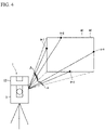
- FIG. 4 is a schematic view to describe setting of a scanning range based on four measurement points
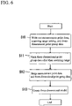
- FIG. 5 is a flowchart of a scanning operation using the survey system 1 according to the present embodiment.
- Step S1 when a start of scanning range setting is commanded from the operation unit 16, the process shifts to Step S1, and the surveying instrument 2 acquires measurement point data.
- the surveying instrument 2 acquires measurement point data.
- a user collimates a target set at the measurement point 9-1 that the user desires to accurately measure, and manually measures a horizontal angle, a vertical angle, and a distance to the measurement point by the surveying instrument 2.
- Step S2 When the measurement of the one measurement point 9-1 is finished, the process shifts to Step S2, and the surveying instrument 2 confirms with the user whether measurements of all measurement points have been finished via the display unit. In a case where the user's answer is "No,” the process returns to Step S1, and the surveying instrument measures a horizontal angle, a vertical angle, and a distance to the next measurement point 9-2, and repeats this operation until measurements of all measurement points are finished. In a case where the user's answer is "Yes,” measurements of the measurement points are ended, and coordinates and angles of the measurement points are stored in the data storage unit 39 of the scanner 22, and the process shifts to Step S3.
- Step S3 from the coordinates of the measurement points 9-1 to 9-4 measured in Step S2, the arithmetic control unit 17 of the surveying instrument 2 extracts two points 9-1 and 9-4 that are most distant from each other in the horizontal direction, and acquires a horizontal included angle ⁇ of these and outputs this angle to the scanner 22.
- the data storage unit 39 of the scanner 22 stores this.
- Step S4 when the process shifts to Step S4, from the coordinates of the measurement points 9-1 and 9-4 measured in Step S2, the arithmetic control unit 17 of the surveying instrument 2 extracts two points 9-2 and 9-3 most distant from each other in the vertical direction, and acquires a vertical included angle ⁇ of these, and stores this angle in the data storage unit 39 of the scanner 22.
- Step S5 when the process shifts to Step S5, the arithmetic control unit 35 of the scanner 22 automatically sets a scanning range 40 based on the coordinates, the horizontal included angle ⁇ , and the vertical included angle ⁇ of the measurement points stored in the data storage unit 39.
- This setting of the scanning range 40 is stored in the data storage unit 39 of the scanner 22.
- the scanning range 40 in the horizontal direction is set so that 180° rotational scanning is performed. A reason for this is described below.
- Step S6 When the scanning range 40 is set, the process shifts to Step S6.
- the arithmetic control unit 35 performs, on the display unit 15, a display to confirm with the user whether to start scanning of the set range 40.
- the process shifts to Step S8, and scanning is started.
- the process shifts to Step S7.
- the user manually sets a scanning range, and this setting is decided and the process shifts to Step S8, and the scanner 22 starts scanning.
- Scanning in the horizontal direction is performed based on the set scanning range 40.
- scanning of 270° including the vertex is performed.
- Step S5 the reason for setting the scanning range 40 to 180° in the horizontal direction when the horizontal included angle ⁇ is in a range of 180° ⁇ ⁇ ⁇ 360° is that scanning of 270° including the vertex in the vertical direction plus scanning of 180° in the horizontal direction is scanning as much as whole circumference scanning in the horizontal direction, and scanning over 180° in the horizontal direction is not necessary. This is because setting of a scanning range is performed for the purpose of shortening a scanning time.
- Step S9 When scanning of the set scanning range is completed, the process shifts to Step S9, and the arithmetic control unit 35 ends scanning, and the data storage unit 39 stores obtained point group data.
- This operation is performed after the above-described scanning operation is ended. This operation may be performed by using an external terminal.
- the external terminal is a terminal, for example, a personal computer, a tablet, etc., and includes a control unit such as a CPU, a storage unit such as a hard disk drive, a display unit such as a liquid crystal display, and an input unit such as a keyboard and a touch display.
- a control unit such as a CPU
- a storage unit such as a hard disk drive
- a display unit such as a liquid crystal display
- an input unit such as a keyboard and a touch display.
- Step S10 the process shifts to Step S10, and the data of measurement points acquired in Step S1, the setting of a scanning range 40 acquired in Step S5, and the three-dimensional point group data acquired in Step S8 are written out from the data storage unit 39 of the scanner to the storage unit of the external terminal.
- Step S11 the process shifts to Step S11, and by using dedicated application software, a portion other than the scanning range 40 in the three-dimensional point group data is masked.
- Step S12 the process shifts to Step S12, and the masked three-dimensional point group data and coordinate data of the measurement points are merged, and then, the process shifts to Step S13, and a three-dimensional model is created.
- a necessary scanning range can be automatically and accurately set based on data of measurement points, so that setting of a scanning range generally considered as being difficult can be easily and preferably performed.
- scanning range setting uses accurate data of the measurement points for creation of a three-dimensional model, so that it is not required to perform a separate operation for scanning range setting. As a result, the process from setting of a scanning range to creation of a three-dimensional model becomes easy.
- a mechanical configuration of a survey system 101 according to a second embodiment is the same as that of the survey system 1 according to the first embodiment, but is different in that a scanning range to be set includes an enlarged scanning range obtained by enlarging an area including all measurement points set in the first embodiment.
- FIG. 7 is a schematic view to describe setting of a scanning range based on the same four measurement points as in FIG. 4
- FIG. 8 is a flowchart of a scanning operation using the survey system 101 according to the present embodiment.
- Step S101 when a start of scanning range setting is commanded from the operation unit 16, the process shifts to Step S101, and the surveying instrument 2 acquires measurement point data in the same manner as in Step S1. That is, a user manually measures a measurement point by the surveying instrument 2.
- Step S102 When the measurement of the measurement point is finished, the process shifts to Step S102, and the arithmetic control unit performs a display to confirm with the user whether measurements of all required measurement points have been finished on the display unit. When the user's answer is "No,” the process returns to Step S101, and this operation is repeated until measurements of all measurement points are finished. When the user's answer is "Yes,” measurements of the measurement points are ended, and coordinates and angles of the measurement points are stored in the data storage unit 39 of the scanner 22, and the process shifts to Step S103.
- Step S103 the arithmetic control unit 17 extracts two measurement points 9-1 and 9-4 most distant from each other in the horizontal direction, and acquires a horizontal included angle ⁇ of these.
- the data on the measurement points and the horizontal included angle ⁇ are stored in the data storage unit 39 of the scanner 22.
- the horizontal included angle ⁇ is 0.
- Step S104 when the process shifts to Step S104, in the same manner as in Step S4, the arithmetic control unit 17 extracts two points 9-2 and 9-3 most distant from each other in the vertical direction, and acquires a vertical included angle ⁇ of these.
- the data on the vertical included angle ⁇ is stored in the data storage unit 39 of the scanner 22.
- the vertical included angle ⁇ is 0.
- Step S105 when the process shifts to Step S105, the arithmetic control unit 35 sets an enlarged scanning range 44 enlarged by a predetermined angle outward from the area 42 including all measurement points.
- the enlarged scanning range 44 in the horizontal direction is a range of an angle ⁇ h leftward in the horizontal direction from the measurement point 9-1 located at the left end of the area 42 including all measurement points and of an angle ⁇ h rightward in the horizontal direction from the measurement point 9-4 located at the right end of the area 42.
- the enlarged scanning range 44 in the vertical direction is a range of an angle ⁇ v in the vertical direction from the measurement point 9-2 located at the upper end of the area 42 including all measurement points and of an angle ⁇ v in the vertical direction from the measurement point 9-3 located at the lower end of the area 42.
- a size of the enlarged scanning range 44 can also be set by distances from measurement point coordinates as well as setting by angles as described above. In addition, the size of the enlarged scanning range can be set so as to be arbitrarily changeable by a user.
- the arithmetic control unit 35 sets a scanning range 140 so that the scanning range includes the area 42 including all measurement points and the enlarged scanning range 44 based on the measurement point data, the horizontal included angle ⁇ , the vertical included angle ⁇ , and the enlarged scanning range 44 setting. That is, the scanning range 140 in the horizontal direction becomes a range enlarged by ⁇ h to both left and right sides of the horizontal included angle ⁇ , and the scanning range 140 in the vertical direction becomes a range enlarged by ⁇ v to both upper and lower sides of the vertical included angle ⁇ .
- the setting of the scanning range 140 is stored in the data storage unit 39 of the scanner 22.
- Step S107 when the process shifts to Step S107, by display on the display unit 15 of the surveying instrument 2, the arithmetic control unit 35 confirms with the user whether to start scanning based on the set scanning range 140.
- the scanning range 140 is decided confirmed, and the process shifts to Step S108, and scanning is started.
- the process shifts to Step S109, and the user manually sets a scanning range, and this scanning range is confirmed, and the process shifts to Step S108 and scanning is started.
- Step S8 When scanning of the set scanning range is completed in the same manner as in Step S8, the process shifts to Step S110, and the arithmetic control unit 35 ends scanning and stores obtained point group data in the storage unit 36.
- the scanning range 140 can be automatically set so as to include the enlarged scanning range 44 at the outer side of the area 42 including all measurement points, so that a necessary region can be easily and accurately set as a scanning range.
- This operation is performed after the scanning operation described above is ended. This operation may be performed by using an external terminal as in the case of the first embodiment.
- Step S111 the process shifts to Step S111, and the data of the measurement points acquired in Step S101, the setting of the scanning range 140 acquired in Step S106, and the three-dimensional point group data acquired in Step S109 are written out from the data storage unit 39 of the scanner 22 to a storage unit of the external terminal.
- Step S112 the process shifts to Step S112, and by using dedicated application software, a portion other than the scanning range 140 in the vertical direction in the three-dimensional point group data is masked.
- the masked three-dimensional point group data may be re-displayed on the display unit of the external terminal so that the scanning range in the vertical direction can be arbitrarily reset by a user.
- Step S113 the process shifts to Step S113, and the masked three-dimensional point group data and the coordinate data of the measurement points are merged, and the process shifts to Step S114, and a three-dimensional model is created.
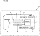
- FIG. 10 is a configuration block diagram of a scanner 222 included in a survey system 201 according to a third embodiment of the present invention.
- the survey system 201 of the present embodiment includes a surveying instrument 2 and a scanner 222 as with the first and second survey systems 1 and 101.
- the surveying instrument 2 has the same configuration, so that the surveying instrument 2 is omitted in FIG. 10 .
- the scanner 222 includes a camera 50 in addition to the configuration of the scanner 22.
- the camera 50 is, for example, a digital camera, and includes an image sensor such as a CCD or a CMOS sensor as an imaging element. Acquired image data is output as a digital signal, and can be acquired as a landscape image.
- an image sensor such as a CCD or a CMOS sensor as an imaging element.
- Acquired image data is output as a digital signal, and can be acquired as a landscape image.
- the camera 50 is connected to an arithmetic processing unit 35 of the scanner 222, and driving of the camera is controlled according to commands of the arithmetic control unit 17 of the surveying instrument 2 via communication between the scanner 222 and the surveying instrument 2.
- Acquired image data is stored in the storage unit 20 of the surveying instrument 2, and displayed on the display unit 15.
- the camera 50 may be provided in the survey system 201 as a camera separate from the scanner 222.
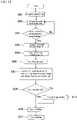
- FIG. 11 is a flowchart of a scanning operation using a survey system 201 according to the present embodiment.
- Step S201 when a start of scanning is commanded from the operation unit 16, the process shifts to Step S201, and the camera 50 acquires a surrounding landscape image and stores it in the storage unit 20.
- Step S202 when the process shifts to Step S202, in the same manner as in Step S1, the surveying instrument 2 acquires measurement point data.
- Step S203 When the measurement of the measurement point is finished, the process shifts to Step S203, and the arithmetic control unit 17 performs a display to confirm with a user whether measurements of all measurement points have been finished on the display unit 15. When the user's answer is "No,” the process returns to Step S202, and this operation is repeated until measurements of all measurement points are finished. When the user's answer is "Yes,” measurements of the measurement points are ended, and coordinates and angles of the measurement points are stored in the data storage unit 39 of the scanner 22, and the process shifts to Step S204.
- Step S204 the arithmetic control unit 17 extracts two measurement points most distant from each other in the horizontal direction, and acquires a horizontal included angle ⁇ of these.
- the data on the measurement points and the horizontal included angle ⁇ are stored in the data storage unit 39 of the scanner 22.
- Step S205 when the process shifts to Step S205, in the same manner as in Step S4, the arithmetic control unit 17 extracts two points most distant from each other in the vertical direction, and acquires a vertical included angle ⁇ of these.
- the data on the vertical included angle ⁇ is stored in the data storage unit 39 of the scanner 22.
- Step S206 when the process shifts to Step S206, in the same manner as in Step S5, the arithmetic control unit 35 of the scanner 22 sets a scanning range based on the coordinates of the measurement points, the horizontal included angle ⁇ , and the vertical included angle ⁇ stored in the data storage unit 39.
- the surveying instrument 2 displays the landscape image acquired in Step S201 on the display unit 15, and displays the data of the measurement points acquired in Step S202 and the scanning range set in Step S206 superimposed on the image.
- Step S208 shifts to Step S208, and it is confirmed with the user whether to start scanning based on the set scanning range.
- the scanning range is decided, and the process shifts to Step S209 and scanning is started.
- the process shifts to Step S210, and the user manually sets a scanning range, and the scanning range is confirmed, and then, the process shifts to Step S209 and scanning is started.
- Step S211 When scanning of the set scanning range is completed, the process shifts to Step S211 and scanning is ended, and the data storage unit 39 stores obtained point group data.
- a three-dimensional model is also created in the same manner as in the first and second embodiments.
- the scanning range 40 can be visually confirmed, and this is convenient. Even in this case, setting itself of the scanning range 40 is automatically performed, so that the area 42 including all required measurement points can be reliably specified.
- FIGS. 12A and 12B illustrate an example in which a scanning range 140 is set with the number of measurement points changed by using the survey system according to the second embodiment
- FIG. 12A illustrates an example in which a scanning range is set by using two measurement points 9-5 and 9-6
- FIG. 12B illustrates an example in which a scanning range is set by using one measurement point 9-7.
- the scanning range 40, 140 can be set by using data of an arbitrary number of measurement points that is at least one, and the number of measurement points is preferably 2 to 4.
Landscapes
- Engineering & Computer Science (AREA)
- Physics & Mathematics (AREA)
- Radar, Positioning & Navigation (AREA)
- Remote Sensing (AREA)
- General Physics & Mathematics (AREA)
- Computer Networks & Wireless Communication (AREA)
- Electromagnetism (AREA)
- Multimedia (AREA)
- Length Measuring Devices By Optical Means (AREA)
- Measurement Of Optical Distance (AREA)
Applications Claiming Priority (1)
| Application Number | Priority Date | Filing Date | Title |
|---|---|---|---|
| JP2017191218A JP6942594B2 (ja) | 2017-09-29 | 2017-09-29 | スキャン範囲設定方法およびそのための測量システム |
Publications (2)
| Publication Number | Publication Date |
|---|---|
| EP3462131A1 EP3462131A1 (en) | 2019-04-03 |
| EP3462131B1 true EP3462131B1 (en) | 2022-12-07 |
Family
ID=63592624
Family Applications (1)
| Application Number | Title | Priority Date | Filing Date |
|---|---|---|---|
| EP18194575.9A Active EP3462131B1 (en) | 2017-09-29 | 2018-09-14 | Scanning range setting method and survey system for the method |
Country Status (3)
| Country | Link |
|---|---|
| US (1) | US11340068B2 (enExample) |
| EP (1) | EP3462131B1 (enExample) |
| JP (1) | JP6942594B2 (enExample) |
Families Citing this family (2)
| Publication number | Priority date | Publication date | Assignee | Title |
|---|---|---|---|---|
| JP7336927B2 (ja) | 2019-09-13 | 2023-09-01 | 株式会社トプコン | 3次元測量装置、3次元測量方法および3次元測量プログラム |
| JP7695093B2 (ja) * | 2021-03-29 | 2025-06-18 | 株式会社トプコン | 測量システム及び点群データ取得方法及び点群データ取得プログラム |
Family Cites Families (7)
| Publication number | Priority date | Publication date | Assignee | Title |
|---|---|---|---|---|
| EP1460377A3 (de) | 2003-03-21 | 2004-09-29 | Leica Geosystems AG | Verfahren und Vorrichtung zur Bildverarbeitung in einem geodätischen Messgerät |
| JP5057734B2 (ja) | 2006-09-25 | 2012-10-24 | 株式会社トプコン | 測量方法及び測量システム及び測量データ処理プログラム |
| JP5466807B2 (ja) | 2006-09-26 | 2014-04-09 | 株式会社トプコン | レーザスキャナ |
| WO2008089791A1 (en) * | 2007-01-26 | 2008-07-31 | Trimble Jena Gmbh | Optical instrument and method for obtaining distance and image information |
| JP5263804B2 (ja) | 2007-04-20 | 2013-08-14 | 株式会社トプコン | 多点測定方法及び測量装置 |
| EP2860550B1 (de) * | 2013-10-09 | 2016-03-02 | Hexagon Technology Center GmbH | Scanner zur Raumvermessung |
| EP3062066B1 (en) | 2015-02-26 | 2025-01-15 | Hexagon Technology Center GmbH | Determination of object data by template-based UAV control |
-
2017
- 2017-09-29 JP JP2017191218A patent/JP6942594B2/ja active Active
-
2018
- 2018-09-06 US US16/123,676 patent/US11340068B2/en active Active
- 2018-09-14 EP EP18194575.9A patent/EP3462131B1/en active Active
Non-Patent Citations (1)
| Title |
|---|
| MAAR HANNES ET AL: "Leica Nova MS60 White paper", 1 August 2017 (2017-08-01), XP055874203, Retrieved from the Internet <URL:https://www.lnrglobalcom.nl/images/brochures/Leica-Nova-MS60-WHP-LR.pdf> [retrieved on 20211217] * |
Also Published As
| Publication number | Publication date |
|---|---|
| JP6942594B2 (ja) | 2021-09-29 |
| EP3462131A1 (en) | 2019-04-03 |
| JP2019066289A (ja) | 2019-04-25 |
| US11340068B2 (en) | 2022-05-24 |
| US20190101389A1 (en) | 2019-04-04 |
Similar Documents
| Publication | Publication Date | Title |
|---|---|---|
| US11004250B2 (en) | Point cloud data display system | |
| JP7163085B2 (ja) | 測量方法、測量装置およびプログラム | |
| EP1903304B1 (en) | Position measuring system, position measuring method and position measuring program | |
| EP1906141B1 (en) | Laser scanner | |
| US10469754B2 (en) | Position guiding device, position guiding method, and position guiding program | |
| EP3812795B1 (en) | Scanner system and scan method | |
| EP3771886A1 (en) | Surveying apparatus, surveying method, and surveying program | |
| EP3460396B1 (en) | Survey system | |
| EP3495769A1 (en) | Surveying device, and calibration method and calibration program for surveying device | |
| EP3514489B1 (en) | Surveying device and surveying method | |
| US20200081098A1 (en) | Handheld laser distance meter | |
| JP7357124B2 (ja) | ターゲット、測量方法およびプログラム | |
| JP6786325B2 (ja) | 測量装置および測定方法 | |
| EP3819590B1 (en) | Management system and management method using eyewear device | |
| EP3462131B1 (en) | Scanning range setting method and survey system for the method | |
| EP3910407A1 (en) | Eyewear display system and eyewear display method | |
| CN112469968B (zh) | 角度检测系统以及角度检测方法 | |
| US10809379B2 (en) | Three-dimensional position measuring system, three-dimensional position measuring method, and measuring module | |
| US20130162971A1 (en) | Optical system | |
| EP3945280B1 (en) | Construction member measuring method and measurement system for the method | |
| JP7511049B2 (ja) | 測量装置、測量方法および測量用プログラム | |
| JP2023077246A (ja) | 測量支援システムおよび測量支援方法 | |
| JP2021067615A (ja) | スキャナシステムおよびスキャン方法 | |
| JP2020020672A (ja) | 測量システム、計測モジュール、および測量方法 | |
| EP3832258A1 (en) | Angle detection system and angle detection method |
Legal Events
| Date | Code | Title | Description |
|---|---|---|---|
| PUAI | Public reference made under article 153(3) epc to a published international application that has entered the european phase |
Free format text: ORIGINAL CODE: 0009012 |
|
| STAA | Information on the status of an ep patent application or granted ep patent |
Free format text: STATUS: THE APPLICATION HAS BEEN PUBLISHED |
|
| AK | Designated contracting states |
Kind code of ref document: A1 Designated state(s): AL AT BE BG CH CY CZ DE DK EE ES FI FR GB GR HR HU IE IS IT LI LT LU LV MC MK MT NL NO PL PT RO RS SE SI SK SM TR |
|
| AX | Request for extension of the european patent |
Extension state: BA ME |
|
| STAA | Information on the status of an ep patent application or granted ep patent |
Free format text: STATUS: REQUEST FOR EXAMINATION WAS MADE |
|
| 17P | Request for examination filed |
Effective date: 20190927 |
|
| RBV | Designated contracting states (corrected) |
Designated state(s): AL AT BE BG CH CY CZ DE DK EE ES FI FR GB GR HR HU IE IS IT LI LT LU LV MC MK MT NL NO PL PT RO RS SE SI SK SM TR |
|
| GRAP | Despatch of communication of intention to grant a patent |
Free format text: ORIGINAL CODE: EPIDOSNIGR1 |
|
| STAA | Information on the status of an ep patent application or granted ep patent |
Free format text: STATUS: GRANT OF PATENT IS INTENDED |
|
| RIC1 | Information provided on ipc code assigned before grant |
Ipc: G01S 17/86 20200101ALI20211214BHEP Ipc: G01S 7/481 20060101ALI20211214BHEP Ipc: G01S 17/42 20060101ALI20211214BHEP Ipc: G01C 15/00 20060101AFI20211214BHEP |
|
| INTG | Intention to grant announced |
Effective date: 20220119 |
|
| RAP3 | Party data changed (applicant data changed or rights of an application transferred) |
Owner name: TOPCON CORPORATION |
|
| GRAJ | Information related to disapproval of communication of intention to grant by the applicant or resumption of examination proceedings by the epo deleted |
Free format text: ORIGINAL CODE: EPIDOSDIGR1 |
|
| STAA | Information on the status of an ep patent application or granted ep patent |
Free format text: STATUS: REQUEST FOR EXAMINATION WAS MADE |
|
| GRAP | Despatch of communication of intention to grant a patent |
Free format text: ORIGINAL CODE: EPIDOSNIGR1 |
|
| STAA | Information on the status of an ep patent application or granted ep patent |
Free format text: STATUS: GRANT OF PATENT IS INTENDED |
|
| INTC | Intention to grant announced (deleted) | ||
| INTG | Intention to grant announced |
Effective date: 20220617 |
|
| GRAS | Grant fee paid |
Free format text: ORIGINAL CODE: EPIDOSNIGR3 |
|
| GRAA | (expected) grant |
Free format text: ORIGINAL CODE: 0009210 |
|
| STAA | Information on the status of an ep patent application or granted ep patent |
Free format text: STATUS: THE PATENT HAS BEEN GRANTED |
|
| AK | Designated contracting states |
Kind code of ref document: B1 Designated state(s): AL AT BE BG CH CY CZ DE DK EE ES FI FR GB GR HR HU IE IS IT LI LT LU LV MC MK MT NL NO PL PT RO RS SE SI SK SM TR |
|
| REG | Reference to a national code |
Ref country code: GB Ref legal event code: FG4D |
|
| REG | Reference to a national code |
Ref country code: CH Ref legal event code: EP Ref country code: AT Ref legal event code: REF Ref document number: 1536554 Country of ref document: AT Kind code of ref document: T Effective date: 20221215 |
|
| REG | Reference to a national code |
Ref country code: DE Ref legal event code: R096 Ref document number: 602018043906 Country of ref document: DE |
|
| REG | Reference to a national code |
Ref country code: IE Ref legal event code: FG4D |
|
| REG | Reference to a national code |
Ref country code: LT Ref legal event code: MG9D |
|
| REG | Reference to a national code |
Ref country code: NL Ref legal event code: MP Effective date: 20221207 |
|
| PG25 | Lapsed in a contracting state [announced via postgrant information from national office to epo] |
Ref country code: SE Free format text: LAPSE BECAUSE OF FAILURE TO SUBMIT A TRANSLATION OF THE DESCRIPTION OR TO PAY THE FEE WITHIN THE PRESCRIBED TIME-LIMIT Effective date: 20221207 Ref country code: NO Free format text: LAPSE BECAUSE OF FAILURE TO SUBMIT A TRANSLATION OF THE DESCRIPTION OR TO PAY THE FEE WITHIN THE PRESCRIBED TIME-LIMIT Effective date: 20230307 Ref country code: LT Free format text: LAPSE BECAUSE OF FAILURE TO SUBMIT A TRANSLATION OF THE DESCRIPTION OR TO PAY THE FEE WITHIN THE PRESCRIBED TIME-LIMIT Effective date: 20221207 Ref country code: FI Free format text: LAPSE BECAUSE OF FAILURE TO SUBMIT A TRANSLATION OF THE DESCRIPTION OR TO PAY THE FEE WITHIN THE PRESCRIBED TIME-LIMIT Effective date: 20221207 Ref country code: ES Free format text: LAPSE BECAUSE OF FAILURE TO SUBMIT A TRANSLATION OF THE DESCRIPTION OR TO PAY THE FEE WITHIN THE PRESCRIBED TIME-LIMIT Effective date: 20221207 |
|
| REG | Reference to a national code |
Ref country code: AT Ref legal event code: MK05 Ref document number: 1536554 Country of ref document: AT Kind code of ref document: T Effective date: 20221207 |
|
| PG25 | Lapsed in a contracting state [announced via postgrant information from national office to epo] |
Ref country code: RS Free format text: LAPSE BECAUSE OF FAILURE TO SUBMIT A TRANSLATION OF THE DESCRIPTION OR TO PAY THE FEE WITHIN THE PRESCRIBED TIME-LIMIT Effective date: 20221207 Ref country code: PL Free format text: LAPSE BECAUSE OF FAILURE TO SUBMIT A TRANSLATION OF THE DESCRIPTION OR TO PAY THE FEE WITHIN THE PRESCRIBED TIME-LIMIT Effective date: 20221207 Ref country code: LV Free format text: LAPSE BECAUSE OF FAILURE TO SUBMIT A TRANSLATION OF THE DESCRIPTION OR TO PAY THE FEE WITHIN THE PRESCRIBED TIME-LIMIT Effective date: 20221207 Ref country code: HR Free format text: LAPSE BECAUSE OF FAILURE TO SUBMIT A TRANSLATION OF THE DESCRIPTION OR TO PAY THE FEE WITHIN THE PRESCRIBED TIME-LIMIT Effective date: 20221207 Ref country code: GR Free format text: LAPSE BECAUSE OF FAILURE TO SUBMIT A TRANSLATION OF THE DESCRIPTION OR TO PAY THE FEE WITHIN THE PRESCRIBED TIME-LIMIT Effective date: 20230308 |
|
| PG25 | Lapsed in a contracting state [announced via postgrant information from national office to epo] |
Ref country code: NL Free format text: LAPSE BECAUSE OF FAILURE TO SUBMIT A TRANSLATION OF THE DESCRIPTION OR TO PAY THE FEE WITHIN THE PRESCRIBED TIME-LIMIT Effective date: 20221207 |
|
| PG25 | Lapsed in a contracting state [announced via postgrant information from national office to epo] |
Ref country code: SM Free format text: LAPSE BECAUSE OF FAILURE TO SUBMIT A TRANSLATION OF THE DESCRIPTION OR TO PAY THE FEE WITHIN THE PRESCRIBED TIME-LIMIT Effective date: 20221207 Ref country code: RO Free format text: LAPSE BECAUSE OF FAILURE TO SUBMIT A TRANSLATION OF THE DESCRIPTION OR TO PAY THE FEE WITHIN THE PRESCRIBED TIME-LIMIT Effective date: 20221207 Ref country code: PT Free format text: LAPSE BECAUSE OF FAILURE TO SUBMIT A TRANSLATION OF THE DESCRIPTION OR TO PAY THE FEE WITHIN THE PRESCRIBED TIME-LIMIT Effective date: 20230410 Ref country code: EE Free format text: LAPSE BECAUSE OF FAILURE TO SUBMIT A TRANSLATION OF THE DESCRIPTION OR TO PAY THE FEE WITHIN THE PRESCRIBED TIME-LIMIT Effective date: 20221207 Ref country code: CZ Free format text: LAPSE BECAUSE OF FAILURE TO SUBMIT A TRANSLATION OF THE DESCRIPTION OR TO PAY THE FEE WITHIN THE PRESCRIBED TIME-LIMIT Effective date: 20221207 Ref country code: AT Free format text: LAPSE BECAUSE OF FAILURE TO SUBMIT A TRANSLATION OF THE DESCRIPTION OR TO PAY THE FEE WITHIN THE PRESCRIBED TIME-LIMIT Effective date: 20221207 |
|
| PG25 | Lapsed in a contracting state [announced via postgrant information from national office to epo] |
Ref country code: SK Free format text: LAPSE BECAUSE OF FAILURE TO SUBMIT A TRANSLATION OF THE DESCRIPTION OR TO PAY THE FEE WITHIN THE PRESCRIBED TIME-LIMIT Effective date: 20221207 Ref country code: IS Free format text: LAPSE BECAUSE OF FAILURE TO SUBMIT A TRANSLATION OF THE DESCRIPTION OR TO PAY THE FEE WITHIN THE PRESCRIBED TIME-LIMIT Effective date: 20230407 Ref country code: AL Free format text: LAPSE BECAUSE OF FAILURE TO SUBMIT A TRANSLATION OF THE DESCRIPTION OR TO PAY THE FEE WITHIN THE PRESCRIBED TIME-LIMIT Effective date: 20221207 |
|
| REG | Reference to a national code |
Ref country code: DE Ref legal event code: R097 Ref document number: 602018043906 Country of ref document: DE |
|
| PLBE | No opposition filed within time limit |
Free format text: ORIGINAL CODE: 0009261 |
|
| STAA | Information on the status of an ep patent application or granted ep patent |
Free format text: STATUS: NO OPPOSITION FILED WITHIN TIME LIMIT |
|
| PG25 | Lapsed in a contracting state [announced via postgrant information from national office to epo] |
Ref country code: DK Free format text: LAPSE BECAUSE OF FAILURE TO SUBMIT A TRANSLATION OF THE DESCRIPTION OR TO PAY THE FEE WITHIN THE PRESCRIBED TIME-LIMIT Effective date: 20221207 |
|
| 26N | No opposition filed |
Effective date: 20230908 |
|
| PG25 | Lapsed in a contracting state [announced via postgrant information from national office to epo] |
Ref country code: SI Free format text: LAPSE BECAUSE OF FAILURE TO SUBMIT A TRANSLATION OF THE DESCRIPTION OR TO PAY THE FEE WITHIN THE PRESCRIBED TIME-LIMIT Effective date: 20221207 |
|
| PG25 | Lapsed in a contracting state [announced via postgrant information from national office to epo] |
Ref country code: LU Free format text: LAPSE BECAUSE OF NON-PAYMENT OF DUE FEES Effective date: 20230914 |
|
| REG | Reference to a national code |
Ref country code: BE Ref legal event code: MM Effective date: 20230930 |
|
| GBPC | Gb: european patent ceased through non-payment of renewal fee |
Effective date: 20230914 |
|
| PG25 | Lapsed in a contracting state [announced via postgrant information from national office to epo] |
Ref country code: LU Free format text: LAPSE BECAUSE OF NON-PAYMENT OF DUE FEES Effective date: 20230914 Ref country code: IT Free format text: LAPSE BECAUSE OF FAILURE TO SUBMIT A TRANSLATION OF THE DESCRIPTION OR TO PAY THE FEE WITHIN THE PRESCRIBED TIME-LIMIT Effective date: 20221207 Ref country code: MC Free format text: LAPSE BECAUSE OF FAILURE TO SUBMIT A TRANSLATION OF THE DESCRIPTION OR TO PAY THE FEE WITHIN THE PRESCRIBED TIME-LIMIT Effective date: 20221207 |
|
| REG | Reference to a national code |
Ref country code: IE Ref legal event code: MM4A |
|
| PG25 | Lapsed in a contracting state [announced via postgrant information from national office to epo] |
Ref country code: IE Free format text: LAPSE BECAUSE OF NON-PAYMENT OF DUE FEES Effective date: 20230914 |
|
| PG25 | Lapsed in a contracting state [announced via postgrant information from national office to epo] |
Ref country code: GB Free format text: LAPSE BECAUSE OF NON-PAYMENT OF DUE FEES Effective date: 20230914 |
|
| PG25 | Lapsed in a contracting state [announced via postgrant information from national office to epo] |
Ref country code: IE Free format text: LAPSE BECAUSE OF NON-PAYMENT OF DUE FEES Effective date: 20230914 Ref country code: GB Free format text: LAPSE BECAUSE OF NON-PAYMENT OF DUE FEES Effective date: 20230914 Ref country code: FR Free format text: LAPSE BECAUSE OF NON-PAYMENT OF DUE FEES Effective date: 20230930 |
|
| PG25 | Lapsed in a contracting state [announced via postgrant information from national office to epo] |
Ref country code: BE Free format text: LAPSE BECAUSE OF NON-PAYMENT OF DUE FEES Effective date: 20230930 |
|
| PG25 | Lapsed in a contracting state [announced via postgrant information from national office to epo] |
Ref country code: BG Free format text: LAPSE BECAUSE OF FAILURE TO SUBMIT A TRANSLATION OF THE DESCRIPTION OR TO PAY THE FEE WITHIN THE PRESCRIBED TIME-LIMIT Effective date: 20221207 |
|
| PG25 | Lapsed in a contracting state [announced via postgrant information from national office to epo] |
Ref country code: BG Free format text: LAPSE BECAUSE OF FAILURE TO SUBMIT A TRANSLATION OF THE DESCRIPTION OR TO PAY THE FEE WITHIN THE PRESCRIBED TIME-LIMIT Effective date: 20221207 |
|
| PGFP | Annual fee paid to national office [announced via postgrant information from national office to epo] |
Ref country code: CH Payment date: 20241001 Year of fee payment: 7 |
|
| PG25 | Lapsed in a contracting state [announced via postgrant information from national office to epo] |
Ref country code: CY Free format text: LAPSE BECAUSE OF FAILURE TO SUBMIT A TRANSLATION OF THE DESCRIPTION OR TO PAY THE FEE WITHIN THE PRESCRIBED TIME-LIMIT; INVALID AB INITIO Effective date: 20180914 |
|
| PG25 | Lapsed in a contracting state [announced via postgrant information from national office to epo] |
Ref country code: HU Free format text: LAPSE BECAUSE OF FAILURE TO SUBMIT A TRANSLATION OF THE DESCRIPTION OR TO PAY THE FEE WITHIN THE PRESCRIBED TIME-LIMIT; INVALID AB INITIO Effective date: 20180914 |
|
| REG | Reference to a national code |
Ref country code: CH Ref legal event code: U11 Free format text: ST27 STATUS EVENT CODE: U-0-0-U10-U11 (AS PROVIDED BY THE NATIONAL OFFICE) Effective date: 20251001 |
|
| PGFP | Annual fee paid to national office [announced via postgrant information from national office to epo] |
Ref country code: DE Payment date: 20250730 Year of fee payment: 8 |