EP3462004A1 - Technique for cooling a combustion engine - Google Patents
Technique for cooling a combustion engine Download PDFInfo
- Publication number
- EP3462004A1 EP3462004A1 EP18189690.3A EP18189690A EP3462004A1 EP 3462004 A1 EP3462004 A1 EP 3462004A1 EP 18189690 A EP18189690 A EP 18189690A EP 3462004 A1 EP3462004 A1 EP 3462004A1
- Authority
- EP
- European Patent Office
- Prior art keywords
- combustion engine
- internal combustion
- heat
- drive shaft
- coupling
- Prior art date
- Legal status (The legal status is an assumption and is not a legal conclusion. Google has not performed a legal analysis and makes no representation as to the accuracy of the status listed.)
- Granted
Links
- 238000002485 combustion reaction Methods 0.000 title claims abstract description 47
- 238000001816 cooling Methods 0.000 title description 14
- 238000000034 method Methods 0.000 title description 2
- 238000010168 coupling process Methods 0.000 claims abstract description 91
- 238000005859 coupling reaction Methods 0.000 claims abstract description 91
- 230000008878 coupling Effects 0.000 claims abstract description 78
- 239000002826 coolant Substances 0.000 claims abstract description 75
- 239000012530 fluid Substances 0.000 claims abstract description 43
- 239000000110 cooling liquid Substances 0.000 claims abstract description 31
- 230000005540 biological transmission Effects 0.000 claims description 8
- 238000012546 transfer Methods 0.000 claims description 4
- 239000002184 metal Substances 0.000 claims description 2
- 238000010586 diagram Methods 0.000 description 7
- 230000001105 regulatory effect Effects 0.000 description 7
- 239000007788 liquid Substances 0.000 description 4
- 230000009467 reduction Effects 0.000 description 4
- 230000001419 dependent effect Effects 0.000 description 3
- XLYOFNOQVPJJNP-UHFFFAOYSA-N water Substances O XLYOFNOQVPJJNP-UHFFFAOYSA-N 0.000 description 3
- QGZKDVFQNNGYKY-UHFFFAOYSA-N Ammonia Chemical compound N QGZKDVFQNNGYKY-UHFFFAOYSA-N 0.000 description 2
- 230000033228 biological regulation Effects 0.000 description 2
- 238000009833 condensation Methods 0.000 description 2
- 230000005494 condensation Effects 0.000 description 2
- 230000001276 controlling effect Effects 0.000 description 2
- 239000012809 cooling fluid Substances 0.000 description 2
- 230000007423 decrease Effects 0.000 description 2
- 239000000446 fuel Substances 0.000 description 2
- 238000013021 overheating Methods 0.000 description 2
- 229920002545 silicone oil Polymers 0.000 description 2
- 239000000654 additive Substances 0.000 description 1
- 230000002776 aggregation Effects 0.000 description 1
- 238000004220 aggregation Methods 0.000 description 1
- 229910021529 ammonia Inorganic materials 0.000 description 1
- 230000002528 anti-freeze Effects 0.000 description 1
- 238000004891 communication Methods 0.000 description 1
- 238000005260 corrosion Methods 0.000 description 1
- 230000007797 corrosion Effects 0.000 description 1
- 230000003247 decreasing effect Effects 0.000 description 1
- 230000000694 effects Effects 0.000 description 1
- 235000015244 frankfurter Nutrition 0.000 description 1
- 238000007710 freezing Methods 0.000 description 1
- 230000008014 freezing Effects 0.000 description 1
- 239000007792 gaseous phase Substances 0.000 description 1
- 239000003112 inhibitor Substances 0.000 description 1
- 238000009434 installation Methods 0.000 description 1
- 238000004519 manufacturing process Methods 0.000 description 1
- 238000012986 modification Methods 0.000 description 1
- 230000004048 modification Effects 0.000 description 1
- 230000000803 paradoxical effect Effects 0.000 description 1
- 230000021715 photosynthesis, light harvesting Effects 0.000 description 1
- 239000003507 refrigerant Substances 0.000 description 1
- 239000002918 waste heat Substances 0.000 description 1
Images

Classifications
-
- F—MECHANICAL ENGINEERING; LIGHTING; HEATING; WEAPONS; BLASTING
- F01—MACHINES OR ENGINES IN GENERAL; ENGINE PLANTS IN GENERAL; STEAM ENGINES
- F01P—COOLING OF MACHINES OR ENGINES IN GENERAL; COOLING OF INTERNAL-COMBUSTION ENGINES
- F01P5/00—Pumping cooling-air or liquid coolants
- F01P5/10—Pumping liquid coolant; Arrangements of coolant pumps
- F01P5/12—Pump-driving arrangements
-
- F—MECHANICAL ENGINEERING; LIGHTING; HEATING; WEAPONS; BLASTING
- F01—MACHINES OR ENGINES IN GENERAL; ENGINE PLANTS IN GENERAL; STEAM ENGINES
- F01P—COOLING OF MACHINES OR ENGINES IN GENERAL; COOLING OF INTERNAL-COMBUSTION ENGINES
- F01P3/00—Liquid cooling
- F01P3/22—Liquid cooling characterised by evaporation and condensation of coolant in closed cycles; characterised by the coolant reaching higher temperatures than normal atmospheric boiling-point
-
- F—MECHANICAL ENGINEERING; LIGHTING; HEATING; WEAPONS; BLASTING
- F01—MACHINES OR ENGINES IN GENERAL; ENGINE PLANTS IN GENERAL; STEAM ENGINES
- F01P—COOLING OF MACHINES OR ENGINES IN GENERAL; COOLING OF INTERNAL-COMBUSTION ENGINES
- F01P3/00—Liquid cooling
- F01P3/02—Arrangements for cooling cylinders or cylinder heads
-
- F—MECHANICAL ENGINEERING; LIGHTING; HEATING; WEAPONS; BLASTING
- F01—MACHINES OR ENGINES IN GENERAL; ENGINE PLANTS IN GENERAL; STEAM ENGINES
- F01P—COOLING OF MACHINES OR ENGINES IN GENERAL; COOLING OF INTERNAL-COMBUSTION ENGINES
- F01P3/00—Liquid cooling
- F01P3/20—Cooling circuits not specific to a single part of engine or machine
-
- F—MECHANICAL ENGINEERING; LIGHTING; HEATING; WEAPONS; BLASTING
- F01—MACHINES OR ENGINES IN GENERAL; ENGINE PLANTS IN GENERAL; STEAM ENGINES
- F01P—COOLING OF MACHINES OR ENGINES IN GENERAL; COOLING OF INTERNAL-COMBUSTION ENGINES
- F01P7/00—Controlling of coolant flow
- F01P7/14—Controlling of coolant flow the coolant being liquid
- F01P7/16—Controlling of coolant flow the coolant being liquid by thermostatic control
- F01P7/162—Controlling of coolant flow the coolant being liquid by thermostatic control by cutting in and out of pumps
-
- F—MECHANICAL ENGINEERING; LIGHTING; HEATING; WEAPONS; BLASTING
- F01—MACHINES OR ENGINES IN GENERAL; ENGINE PLANTS IN GENERAL; STEAM ENGINES
- F01P—COOLING OF MACHINES OR ENGINES IN GENERAL; COOLING OF INTERNAL-COMBUSTION ENGINES
- F01P7/00—Controlling of coolant flow
- F01P7/14—Controlling of coolant flow the coolant being liquid
- F01P7/16—Controlling of coolant flow the coolant being liquid by thermostatic control
- F01P7/164—Controlling of coolant flow the coolant being liquid by thermostatic control by varying pump speed
-
- F—MECHANICAL ENGINEERING; LIGHTING; HEATING; WEAPONS; BLASTING
- F02—COMBUSTION ENGINES; HOT-GAS OR COMBUSTION-PRODUCT ENGINE PLANTS
- F02B—INTERNAL-COMBUSTION PISTON ENGINES; COMBUSTION ENGINES IN GENERAL
- F02B67/00—Engines characterised by the arrangement of auxiliary apparatus not being otherwise provided for, e.g. the apparatus having different functions; Driving auxiliary apparatus from engines, not otherwise provided for
- F02B67/04—Engines characterised by the arrangement of auxiliary apparatus not being otherwise provided for, e.g. the apparatus having different functions; Driving auxiliary apparatus from engines, not otherwise provided for of mechanically-driven auxiliary apparatus
-
- F—MECHANICAL ENGINEERING; LIGHTING; HEATING; WEAPONS; BLASTING
- F04—POSITIVE - DISPLACEMENT MACHINES FOR LIQUIDS; PUMPS FOR LIQUIDS OR ELASTIC FLUIDS
- F04D—NON-POSITIVE-DISPLACEMENT PUMPS
- F04D13/00—Pumping installations or systems
- F04D13/02—Units comprising pumps and their driving means
- F04D13/021—Units comprising pumps and their driving means containing a coupling
-
- F—MECHANICAL ENGINEERING; LIGHTING; HEATING; WEAPONS; BLASTING
- F04—POSITIVE - DISPLACEMENT MACHINES FOR LIQUIDS; PUMPS FOR LIQUIDS OR ELASTIC FLUIDS
- F04D—NON-POSITIVE-DISPLACEMENT PUMPS
- F04D15/00—Control, e.g. regulation, of pumps, pumping installations or systems
-
- F—MECHANICAL ENGINEERING; LIGHTING; HEATING; WEAPONS; BLASTING
- F16—ENGINEERING ELEMENTS AND UNITS; GENERAL MEASURES FOR PRODUCING AND MAINTAINING EFFECTIVE FUNCTIONING OF MACHINES OR INSTALLATIONS; THERMAL INSULATION IN GENERAL
- F16D—COUPLINGS FOR TRANSMITTING ROTATION; CLUTCHES; BRAKES
- F16D35/00—Fluid clutches in which the clutching is predominantly obtained by fluid adhesion
- F16D35/005—Fluid clutches in which the clutching is predominantly obtained by fluid adhesion with multiple lamellae
-
- F—MECHANICAL ENGINEERING; LIGHTING; HEATING; WEAPONS; BLASTING
- F28—HEAT EXCHANGE IN GENERAL
- F28D—HEAT-EXCHANGE APPARATUS, NOT PROVIDED FOR IN ANOTHER SUBCLASS, IN WHICH THE HEAT-EXCHANGE MEDIA DO NOT COME INTO DIRECT CONTACT
- F28D15/00—Heat-exchange apparatus with the intermediate heat-transfer medium in closed tubes passing into or through the conduit walls ; Heat-exchange apparatus employing intermediate heat-transfer medium or bodies
- F28D15/02—Heat-exchange apparatus with the intermediate heat-transfer medium in closed tubes passing into or through the conduit walls ; Heat-exchange apparatus employing intermediate heat-transfer medium or bodies in which the medium condenses and evaporates, e.g. heat pipes
- F28D15/04—Heat-exchange apparatus with the intermediate heat-transfer medium in closed tubes passing into or through the conduit walls ; Heat-exchange apparatus employing intermediate heat-transfer medium or bodies in which the medium condenses and evaporates, e.g. heat pipes with tubes having a capillary structure
-
- F—MECHANICAL ENGINEERING; LIGHTING; HEATING; WEAPONS; BLASTING
- F01—MACHINES OR ENGINES IN GENERAL; ENGINE PLANTS IN GENERAL; STEAM ENGINES
- F01P—COOLING OF MACHINES OR ENGINES IN GENERAL; COOLING OF INTERNAL-COMBUSTION ENGINES
- F01P3/00—Liquid cooling
- F01P3/02—Arrangements for cooling cylinders or cylinder heads
- F01P2003/021—Cooling cylinders
-
- F—MECHANICAL ENGINEERING; LIGHTING; HEATING; WEAPONS; BLASTING
- F01—MACHINES OR ENGINES IN GENERAL; ENGINE PLANTS IN GENERAL; STEAM ENGINES
- F01P—COOLING OF MACHINES OR ENGINES IN GENERAL; COOLING OF INTERNAL-COMBUSTION ENGINES
- F01P3/00—Liquid cooling
- F01P3/02—Arrangements for cooling cylinders or cylinder heads
- F01P2003/024—Cooling cylinder heads
-
- F—MECHANICAL ENGINEERING; LIGHTING; HEATING; WEAPONS; BLASTING
- F01—MACHINES OR ENGINES IN GENERAL; ENGINE PLANTS IN GENERAL; STEAM ENGINES
- F01P—COOLING OF MACHINES OR ENGINES IN GENERAL; COOLING OF INTERNAL-COMBUSTION ENGINES
- F01P3/00—Liquid cooling
- F01P3/22—Liquid cooling characterised by evaporation and condensation of coolant in closed cycles; characterised by the coolant reaching higher temperatures than normal atmospheric boiling-point
- F01P2003/2278—Heat pipes
-
- F—MECHANICAL ENGINEERING; LIGHTING; HEATING; WEAPONS; BLASTING
- F16—ENGINEERING ELEMENTS AND UNITS; GENERAL MEASURES FOR PRODUCING AND MAINTAINING EFFECTIVE FUNCTIONING OF MACHINES OR INSTALLATIONS; THERMAL INSULATION IN GENERAL
- F16D—COUPLINGS FOR TRANSMITTING ROTATION; CLUTCHES; BRAKES
- F16D2300/00—Special features for couplings or clutches
- F16D2300/02—Overheat protection, i.e. means for protection against overheating
- F16D2300/021—Cooling features not provided for in group F16D13/72 or F16D25/123, e.g. heat transfer details
- F16D2300/0214—Oil or fluid cooling
-
- F—MECHANICAL ENGINEERING; LIGHTING; HEATING; WEAPONS; BLASTING
- F16—ENGINEERING ELEMENTS AND UNITS; GENERAL MEASURES FOR PRODUCING AND MAINTAINING EFFECTIVE FUNCTIONING OF MACHINES OR INSTALLATIONS; THERMAL INSULATION IN GENERAL
- F16D—COUPLINGS FOR TRANSMITTING ROTATION; CLUTCHES; BRAKES
- F16D35/00—Fluid clutches in which the clutching is predominantly obtained by fluid adhesion
- F16D35/02—Fluid clutches in which the clutching is predominantly obtained by fluid adhesion with rotary working chambers and rotary reservoirs, e.g. in one coupling part
- F16D35/021—Fluid clutches in which the clutching is predominantly obtained by fluid adhesion with rotary working chambers and rotary reservoirs, e.g. in one coupling part actuated by valves
- F16D35/022—Fluid clutches in which the clutching is predominantly obtained by fluid adhesion with rotary working chambers and rotary reservoirs, e.g. in one coupling part actuated by valves the valve being actuated by a bimetallic strip
Definitions
- the invention relates to an internal combustion engine, for example for driving a motor vehicle.
- a technique for cooling a viscous coupling of the internal combustion engine is described.
- visco-couplings are used to controllably drive a coolant pump of the coolant circuit of the internal combustion engine.
- An engine rigidly coupled to the engine coolant pump of a truck (truck) would have an average power consumption of, for example, 7 kW.
- the full power of the coolant pump is often not necessary (for example in the case of a horizontal travel route and high driving speed) for a sufficient heat flow through the coolant of the internal combustion engine.
- between 0.5 and 1.5 percent of the fuel can be saved by a demand-adjusted control of the coolant pump.
- An example of such a conventional control of the coolant pump is described in the article "Just turn off" the Frankfurterirrie Symposium, 29 April 2013.
- the visco coupling of a controllable coolant pump uses the controllable torque transmission of the visco coupling.
- Torque transmission is based on the fluid properties of a clutch fluid in the visco-coupling.
- tough silicone oil serves as the coupling fluid. Due to the different speeds between the drive shaft and output shaft of the viscous coupling, the coupling fluid is sheared, and the shear forces transmitted by the coupling fluid, the torque from the drive shaft to the output shaft. Since the shear forces are due to the viscosity, i.
- the torque transmission of the visco-coupling is associated with energy dissipation which is transferred as heat both inwardly (i.e., into the clutch fluid) and outward (i.e., via a housing of the visco-clutch to the environment).
- the internal heat input degrades the hydraulic properties of the clutch fluid, as typically the viscosity and torque transmission efficiency decreases with increasing clutch fluid temperature.
- the control range of a conventional viscous coupling is limited, especially at high engine speeds, so as not to shorten the life of the viscous coupling.
- This can lead to the paradoxical control situation that the controllable viscous coupling at high engine speed can not be regulated for a reduced speed of the coolant pump to prevent overheating of the viscous coupling. That is, the coolant pump must be operated with a power that would not be necessary for cooling the internal combustion engine.
- the object is to provide an internal combustion engine with a more energy-efficient cooling.
- An alternative or further object is to increase the controllability of the visco-coupling without limiting the life of the viscous coupling.
- An alternative or further object is, regardless of the mechanical load of the viscous coupling and ambient temperatures to ensure the most constant temperature of the coupling fluid.
- an internal combustion engine comprises a coolant circuit, which is connected or connectable to a cylinder head and / or an engine block of the internal combustion engine.
- the cooling liquid circuit comprises a cooling liquid pump, which comprises a drive shaft and is designed to convey cooling liquid in the cooling liquid circuit.
- the internal combustion engine comprises a viscous coupling, which is arranged or can be arranged for driving by the internal combustion engine, comprises a coupling fluid for transmitting torque, and the output side is connected to the drive shaft of the coolant pump.
- the drive shaft of the coolant pump comprises at least one heat pipe, which is in heat exchange with the clutch fluid as a heat source and the coolant as a heat sink or can be brought.
- the waste heat flow from the clutch fluid as the heat source to the coolant as the heat sink can be efficiently transmitted.
- At least one heat pipe may be inserted through a longitudinal bore in the drive shaft as an encapsulated unit.
- at least one heat pipe can be realized integrally with the drive shaft in a longitudinal bore of the drive shaft.
- the coupling fluid may comprise an oil, for example silicone oil.
- the coupling fluid can have certain hydraulic properties for transmitting torque, for example a specific temperature-dependent viscosity.
- the cooling fluid may include water, an antifreeze and / or a corrosion inhibitor.
- the viscous coupling may include louvers surrounded by clutch fluid.
- the slats can be rotatably connected to the drive shaft.
- the heat pipe can be in heat exchange with the coupling fluid as a heat source via the fins.
- the lamellae are arranged circumferentially on a coupling-side end of the drive shaft.
- a heat source side end of the heat pipe may correspond to the coupling side end of the drive shaft.
- the coolant pump may comprise an impeller (for example an impeller) surrounded by the coolant.
- the impeller may be rotatably connected to the drive shaft.
- the heat pipe can be in heat exchange with the cooling liquid as a heat sink.
- the impeller is arranged circumferentially on a pump-side end of the drive shaft.
- a heat-sink-side end of the heat pipe may correspond to the pump-side end of the drive shaft.
- the coolant circuit may further include a radiator and a thermostat.
- the coolant pump may be connected on the input side to the radiator and / or the thermostat.
- the coolant pump can the output side with the cylinder head and / or be connected to the engine block.
- the radiator and / or the thermostat may be located downstream in the coolant circuit to the engine block.
- the heat pipe may comprise a capillary or a plurality of capillaries extending in the longitudinal direction of the drive shaft, for example from the coupling end to the pump end of the drive shaft.
- the capillary or at least one of the capillaries may be arranged coaxially with the drive shaft.
- the heat pipe may comprise a plurality of capillaries (for example, through a porous structure) and be arranged coaxially in the drive shaft. Due to the coaxial arrangement, centrifugal forces can be minimized or eliminated on the heat pipe.
- the heat pipe may comprise a cooling medium (in short: medium).
- the cooling medium may be configured to evaporate by thermal contact with the heat source (eg, at the clutch-side end of the drive shaft) and to condense by thermal contact with the heat sink (eg, at the pump-side end of the drive shaft).
- the heat pipe can be a closed system that contains the cooling medium.
- the cooling medium may comprise, for example, water or ammonia.
- the cooling medium may flow from the heat sink (eg, the pump-side end of the drive shaft) to the heat source (eg, the clutch-side end of the drive shaft) by capillary forces in the liquid state, for example, in the capillaries or the porous structure.
- the flow of the cooling medium in the gaseous state from the heat source to the heat sink can be spatially decoupled from the return flow of the cooling medium in the liquid state of aggregation.
- the heat pipe may include a centrifugal force-free condensation channel (coaxially disposed in the drive shaft) and a vapor channel surrounding the condensation channel.
- a thermal resistance of a heat conduction in the metal of the drive shaft can be several times greater than a thermal resistance of a heat transfer in the heat pipe.
- the coexistence of a liquid and a gaseous phase of the cooling medium in the heat pipe, the coupling-side end of the drive shaft and the pump-side end of the drive shaft may be almost isothermal.
- the device may comprise a control unit which controls a degree of coupling of the viscous coupling.
- a control unit which controls a degree of coupling of the viscous coupling.
- the degree of coupling depending on a temperature of the Cooling liquid and / or a temperature gradient in the engine block and / or the cylinder head are regulated.
- a heat capacity of the cooling liquid may be several times greater than a heat capacity of the coupling fluid. Due to the unequal heat capacities and the low heat resistance of the heat pipe, the temperature of the coupling fluid can follow the temperature of the cooling liquid or almost correspond. A regulation of the cooling liquid may imply a regulation of the coupling fluid.
- a control range of the controllable visco-clutch compared to a conventional air-cooled viscous coupling can be increased, for example, include the entire speed range of the internal combustion engine.
- a vehicle for example, a land vehicle or a watercraft, which includes an internal combustion engine according to an embodiment of the aforementioned aspect.
- the land vehicle may in particular be a commercial vehicle, for example a bus, a truck or a tractor.
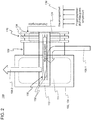
- FIG. 1 shows a first embodiment of a generally designated by reference numeral 100 internal combustion engine.
- Internal combustion engine 100 includes a cylinder head 102 and an engine block 104 which are connected to a coolant circuit generally designated by reference numeral 106.
- the internal combustion engine 100 further includes a coolant pump 108, which is connected on the input side to an inlet 106-1 of the coolant circuit 106. On the output side, the coolant pump 108 is in fluid communication with cooling lines in the cylinder head 102 and in the engine block 104.
- the coolant pump 108 includes in a pump housing an impeller 110 (eg, an impeller or a propeller) on a drive shaft 112. Impeller 110 and a pump-side end of the drive shaft 112 are immersed in a coolant 114 of the coolant circuit 106 which fills the pump housing.
- the cooling liquid 114 includes, for example, water with additives for freezing point increase and viscosity reduction.
- the controllable rotational speed of the coolant pump 108 determines the amount of cooling fluid 114 circulating in the coolant circuit 106 per unit time.
- the coolant circuit 106 comprises a radiator 116 downstream of the engine block 104 at its return 106-2, which is relative to the inlet 106-1.
- the coolant circuit 106 also comprises a thermostat 118. The thermostat 118 determines a proportion of the cooling liquid 114 flowing through the radiator 116 at the cooling liquid 114 circulating through the internal combustion engine.
- the drive shaft 112 is coupled to the output of a viscous coupling 120, which is arranged to the drive 122 by the internal combustion engine 100.
- the drive 122 of the viscous coupling 120 may include a fixed gear ratio transmission to the crankshaft of the engine 100.
- the viscous coupling 120 comprises a coupling fluid 124 whose viscosity transmits the torque applied to outer disks 128 on the drive side to inner disks 126.
- the inner disks 126 are rotatably mounted on the drive shaft 112 at a coupling-side end of the drive shaft 112.
- At least one heat pipe 130 for dissipating heat from the coupling fluid 124 to the cooling liquid 114 is arranged.
- the clutch-side end of the heat pipe 130 is in heat exchange with the clutch fluid 124 via the inner blades 126 as a heat source.
- the pump-side end of the heat pipe 130 is in heat exchange with the cooling liquid 114 via the impeller 110 as a heat sink.
- FIG. 2 shows a schematic block diagram of a second embodiment of the internal combustion engine 100. Individual features of the second embodiment are combined with those of the first embodiment and / or can replace them. In particular are corresponding or replaceable features provided with matching reference numerals.
- a thermally convective cooling medium is used as the coolant.
- Suitable cooling medium are organic and / or inorganic coolants (which can also be used, for example, as refrigerants).
- a coupling-side first end of the heat pipe which is in thermal contact with the viscous coupling 120 (more precisely, the coupling fluid 124) as a heat source, serves as an evaporator of the cooling medium in the heat pipe 130.
- a pump-side second, the first end opposite end of the heat pipe 130 stands with the cooling liquid pump 108 (more precisely, the cooling liquid 114) as a heat sink in thermal contact and serves as a condenser of the cooling medium.
- the heat pipe 130 comprises a capillary 132 or a plurality of capillaries 132, in which the cooling medium is enclosed.
- the cooling medium in the liquid state of aggregate flows from the pump-side second end to the coupling-side first end.
- a recirculation of the cooling medium for effective heat transfer along the drive shaft 112 is achieved.
- the built in the drive shaft 112 heat pipe 130 allows a nearly constant temperature of the coupling fluid 124 due to the close thermal connection to the regulated temperature of the cooling liquid 114. Since the temperature of the coupling fluid 124 affects the efficiency of the viscous coupling 120, a heat-induced slip effect is avoided or significantly reduced.
- the effective thermal connection to the cooling liquid 114 allows a reduction of the cooling ribs 134 on the viscous coupling 120 or a waiver of such cooling fins 134.
- manufacturing costs of the viscous coupling 120 and the weight of the viscous coupling 120 can be reduced.
- a conventional air cooling of the viscous coupling 120 is no longer necessary or can be significantly reduced.
- the Cost and installation space for the viscous coupling 120 are thereby reduced.
- a life of the viscous coupling 120 may be increased because of the stable constant temperature of the coupling fluid 124 over conventional viscous couplings.
- the engine 100 may include a control unit 136 that controls the speed of the coolant pump 108 via the viscous coupling 120. Since the control of the pump speed is dependent on input variables of the control unit 136, such as the measured temperature of the cooling liquid 114 and / or a measured temperature gradient in the cylinder head 102 and / or engine block 104, this temperature or temperature gradient is regulated.
- the control unit 136 may be referred to as regulating the rotational speed of the coolant pump 108.
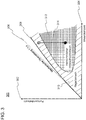
- FIG. 3 11 shows a schematic speed diagram 300 for controlling the viscous coupling 120, and thus the rotational speed 302 of the coolant pump 108.
- the control shown schematically in the diagram 300 is applicable to any exemplary embodiment of the internal combustion engine 100.
- the rotational speed 304 of the engine i.e., the rotational speed of the crankshaft
- the straight line of origin 306 represents the mechanical gear ratio (for example, 1: 1.8 relative to the crankshaft), i.
- the speed of the drive 122 of the viscous coupling 120 Due to the slip also required for maximum coupled viscous coupling 120 for torque transmission, the maximum speed 308 on the output side of the viscous coupling 120, i. the maximum speed 308 of the drive shaft 112, less than the speed 306.
- This minimum slip is negligible at low load or engine speed 304 and increases with the load or engine speed 304.
- control range 310 below the maximum rotational speed 308 of the control unit 136 for regulating the viscous coupling 120 may be available.
- a restriction of the control range 310 by a conventional heat-slip region (also: heat-slip region) can be eliminated by the thermal connection via the heat pipe 130.
- the conventional heat slip region 312 may occur due to high heat output at high engine speed 304 and / or high shear forces (ie, high load torque) in the clutch fluid of a conventional visco-clutch (eg, air-cooled only) lead to an uncontrolled increase in temperature in the clutch fluid 124, so that due to the decreasing viscosity with the temperature and / or overheating of the clutch fluid 124, the conventional Hitzeschlupf Scheme 312 in the control of a conventional viscous coupling is not available.
- a conventional visco-clutch eg, air-cooled only
- the heat-loss range can be reduced or irrelevant to the control range 310.
- a reduction 314 of the pump speed 302 is made possible. This option is not available with a conventional viscous coupling due to the conventional heat-rejection range 312 of the control.
Abstract
Eine Brennkraftmaschine (100) wird beschrieben. Die Brennkraftmaschine (100) umfasst einen Kühlflüssigkeitskreislauf (106-1, 106-2), der an einen Zylinderkopf (102) und einen Motorblock (104) der Brennkraftmaschine (100) angeschlossen ist und eine Kühlflüssigkeitspumpe (108) umfasst. Die Kühlflüssigkeitspumpe (108) umfasst eine Antriebswelle (112) und vermag Kühlflüssigkeit (114) im Kühlflüssigkeitskreislauf (106-1, 106-2) zu fördern. Ferner umfasst die Brennkraftmaschine (100) eine Visco-Kupplung (120). Die Visco-Kupplung (120) ist zum Antrieb (122) durch die Brennkraftmaschine (100) angeordnet. Die Visco-Kupplung (120) umfasst ein Kupplungsfluid (124) zur Drehmomentübertragung. Abtriebsseitig ist die Visco-Kupplung (120) mit der Antriebswelle (112) der Kühlflüssigkeitspumpe (108) verbunden. Die Antriebswelle (112) der Kühlflüssigkeitspumpe (108) umfasst mindestens ein Wärmerohr (130). Das Wärmerohr (130) steht in Wärmeaustausch mit dem Kupplungsfluid (124) als Wärmequelle und der Kühlflüssigkeit (114) als Wärmesenke.

Description
Die Erfindung betrifft eine Brennkraftmaschine, beispielsweise zum Antrieb eines Kraftfahrzeugs. Insbesondere ist eine Technik zur Kühlung einer Visco-Kupplung der Brennkraftmaschine beschrieben.The invention relates to an internal combustion engine, for example for driving a motor vehicle. In particular, a technique for cooling a viscous coupling of the internal combustion engine is described.
Bei Kraftfahrzeugen, insbesondere Nutzfahrzeugen, werden Visco-Kupplungen eingesetzt, um eine Kühlflüssigkeitspumpe des Kühlflüssigkeitskreislaufs der Brennkraftmaschine regelbar anzutreiben. Eine an die Brennkraftmaschine starr gekoppelte Kühlflüssigkeitspumpe eines Lastkraftwagens (LKW) würde eine durchschnittliche Leistungsaufnahme von beispielsweise 7 kW aufweisen. Die volle Leistung der Kühlflüssigkeitspumpe ist (beispielsweise bei horizontaler Fahrstrecke und hoher Fahrgeschwindigkeit) oft nicht notwendig für einen hinreichenden Wärmeabfluss durch die Kühlflüssigkeit der Brennkraftmaschine. Durch eine bedarfsangepasste Regelung der Kühlflüssigkeitspumpe können beispielsweise zwischen 0,5 und 1,5 Prozent des Treibstoffs eingespart werden. Ein Beispiel einer solchen herkömmlichen Regelung der Kühlflüssigkeitspumpe ist im Artikel "Einfach mal abschalten" der Frankfurter Allgemeinen Zeitung vom 29. April 2013 beschrieben.In motor vehicles, especially commercial vehicles, visco-couplings are used to controllably drive a coolant pump of the coolant circuit of the internal combustion engine. An engine rigidly coupled to the engine coolant pump of a truck (truck) would have an average power consumption of, for example, 7 kW. The full power of the coolant pump is often not necessary (for example in the case of a horizontal travel route and high driving speed) for a sufficient heat flow through the coolant of the internal combustion engine. For example, between 0.5 and 1.5 percent of the fuel can be saved by a demand-adjusted control of the coolant pump. An example of such a conventional control of the coolant pump is described in the article "Just turn off" the Frankfurter Allgemeine Zeitung, 29 April 2013.
Die Visco-Kupplung einer regelbaren Kühlflüssigkeitspumpe nutzt die regelbare Drehmomentübertragung der Visco-Kupplung. Die Drehmomentübertragung basiert auf den Flüssigkeitseigenschaften eines Kupplungsfluids in der Visco-Kupplung. Beispielsweise dient zähes Silikonöl als Kupplungsfluid. Durch die unterschiedlichen Drehzahlen zwischen Antriebswelle und Abtriebswelle der Visco-Kupplung wird das Kupplungsfluid geschert, und die Scherkräfte übertragen mittels des Kupplungsfluids das Drehmoment von der Antriebswelle zur Abtriebswelle. Da die Scherkräfte auf der Viskosität, d.h. der inneren Reibung, des Kupplungsfluids beruhen, ist die Drehmomentübertragung der Visco-Kupplung mit Energiedissipation verbunden, die als Wärme sowohl nach innen (d.h. ins Kupplungsfluid) als auch nach außen (d.h. über ein Gehäuse der Visco-Kupplung an die Umgebung) übertragen wird.The visco coupling of a controllable coolant pump uses the controllable torque transmission of the visco coupling. Torque transmission is based on the fluid properties of a clutch fluid in the visco-coupling. For example, tough silicone oil serves as the coupling fluid. Due to the different speeds between the drive shaft and output shaft of the viscous coupling, the coupling fluid is sheared, and the shear forces transmitted by the coupling fluid, the torque from the drive shaft to the output shaft. Since the shear forces are due to the viscosity, i. Based on the internal friction of the clutch fluid, the torque transmission of the visco-coupling is associated with energy dissipation which is transferred as heat both inwardly (i.e., into the clutch fluid) and outward (i.e., via a housing of the visco-clutch to the environment).
Jedoch verschlechtert der innere Wärmeeintrag die hydraulischen Eigenschaften des Kupplungsfluids, da typischerweise die Viskosität und der Wirkungsgrad der Drehmomentübertragung mit steigender Temperatur des Kupplungsfluids abnehmen. Somit ist der Regelbereich einer herkömmlichen Visco-Kupplung insbesondere bei hohen Motordrehzahlen eingeschränkt, um die Lebensdauer der Visco-Kupplung nicht zu verkürzen. Dies kann zu der paradoxen Regelungssituation führen, dass die regelbare Visco-Kupplung bei hoher Motordrehzahl nicht für eine reduzierte Drehzahl der Kühlflüssigkeitspumpe geregelt werden kann, um eine Überhitzung der Visco-Kupplung zu verhindern. Das heißt die Kühlflüssigkeitspumpe muss mit einer Leistung betrieben werden, die zur Kühlung der Brennkraftmaschine gar nicht notwendig wäre.However, the internal heat input degrades the hydraulic properties of the clutch fluid, as typically the viscosity and torque transmission efficiency decreases with increasing clutch fluid temperature. Thus, the control range of a conventional viscous coupling is limited, especially at high engine speeds, so as not to shorten the life of the viscous coupling. This can lead to the paradoxical control situation that the controllable viscous coupling at high engine speed can not be regulated for a reduced speed of the coolant pump to prevent overheating of the viscous coupling. That is, the coolant pump must be operated with a power that would not be necessary for cooling the internal combustion engine.
Alternative Maßnahmen zur Kühlung der Visco-Kupplung, wie beispielsweise die Vergrößerung einer Berippung am Gehäuse der Visco-Kupplung sind nicht zielführend. Zum einen wird durch die größere Berippung die rotierende Masse der Visco-Kupplung erhöht und der notwendige Bauraum vergrößert. Andererseits ist gerade diese Luftkühlung unzureichend, da die Kühlflüssigkeitspumpe bei hoher Motorlast zugeschaltet wird, wodurch die hinter dem Radiator angeordnete Visco-Kupplung von der ebenfalls erhöhten Temperatur der Kühlluft überstrichen wird.Alternative measures for cooling the viscous coupling, such as the enlargement of a ribbing on the housing of the viscous coupling are not effective. On the one hand, the larger ribbing increases the rotating mass of the visco-coupling and increases the necessary space. On the other hand, just this air cooling is insufficient, since the coolant pump is switched on at high engine load, whereby the disposed behind the radiator viscous coupling is swept by the also increased temperature of the cooling air.
Somit besteht die Aufgabe, eine Brennkraftmaschine mit einer energieeffizienteren Kühlung bereitzustellen. Eine Alternative oder weitere Aufgabe ist die Regelbarkeit der Visco-Kupplung ohne Einschränkung der Lebensdauer der Visco-Kupplung zu erhöhen. Eine Alternative oder weitere Aufgabe ist, unabhängig von der mechanischen Belastung der Visco-Kupplung und Umgebungstemperaturen eine möglichst konstante Temperatur des Kupplungsfluids sicherzustellen.Thus, the object is to provide an internal combustion engine with a more energy-efficient cooling. An alternative or further object is to increase the controllability of the visco-coupling without limiting the life of the viscous coupling. An alternative or further object is, regardless of the mechanical load of the viscous coupling and ambient temperatures to ensure the most constant temperature of the coupling fluid.
Diese Aufgabe oder Aufgaben werden durch eine Brennkraftmaschine und ein entsprechendes Kraftfahrzeug mit den Merkmalen der unabhängigen Ansprüche gelöst. Vorteilhafte Ausführungsformen und Anwendungen der Erfindung sind Gegenstand der abhängigen Ansprüche und werden in der folgenden Beschreibung unter teilweiser Bezugnahme auf die Figuren näher erläutert.This object or objects are achieved by an internal combustion engine and a corresponding motor vehicle having the features of the independent claims. Advantageous embodiments and applications of the invention are the subject matter of the dependent claims and are explained in more detail in the following description with partial reference to the figures.
Gemäß einem Aspekt der Erfindung wird eine Brennkraftmaschine bereitgestellt. Die Brennkraftmaschine umfasst einen Kühlflüssigkeitskreislauf, der an einem Zylinderkopf und/oder einem Motorblock der Brennkraftmaschine angeschlossen oder anschließbar ist. Der Kühlflüssigkeitskreislauf umfasst eine Kühlflüssigkeitspumpe, die eine Antriebswelle umfasst und dazu ausgebildet ist, Kühlflüssigkeit im Kühlflüssigkeitskreislauf zu fördern. Ferner umfasst die Brennkraftmaschine eine Visco-Kupplung, die zum Antrieb durch die Brennkraftmaschine angeordnet oder anordenbar ist, ein Kupplungsfluid zur Drehmomentübertragung umfasst und abtriebsseitig mit der Antriebswelle der Kühlflüssigkeitspumpe verbunden ist. Die Antriebswelle der Kühlflüssigkeitspumpe umfasst mindestens ein Wärmerohr, das mit dem Kupplungsfluid als Wärmequelle und der Kühlflüssigkeit als Wärmesenke in Wärmeaustausch steht oder bringbar ist.According to one aspect of the invention, an internal combustion engine is provided. The internal combustion engine comprises a coolant circuit, which is connected or connectable to a cylinder head and / or an engine block of the internal combustion engine. The cooling liquid circuit comprises a cooling liquid pump, which comprises a drive shaft and is designed to convey cooling liquid in the cooling liquid circuit. Furthermore, the internal combustion engine comprises a viscous coupling, which is arranged or can be arranged for driving by the internal combustion engine, comprises a coupling fluid for transmitting torque, and the output side is connected to the drive shaft of the coolant pump. The drive shaft of the coolant pump comprises at least one heat pipe, which is in heat exchange with the clutch fluid as a heat source and the coolant as a heat sink or can be brought.
Indem mindestens ein Wärmerohr in der Antriebswelle der regelbaren Kühlflüssigkeitspumpe vorhanden ist, kann der Abwärmestrom von dem Kupplungsfluid als Wärmequelle zur Kühlflüssigkeit als Wärmesenke wirksam übertragen werden.By having at least one heat pipe in the drive shaft of the variable coolant pump, the waste heat flow from the clutch fluid as the heat source to the coolant as the heat sink can be efficiently transmitted.
Mindestens ein Wärmerohr kann durch eine Längsbohrung in der Antriebswelle als gekapselte Einheit eingesetzt sein. Alternativ oder ergänzend kann mindestens ein Wärmerohr integraleinstückig mit der Antriebswelle in einer Längsbohrung der Antriebswelle realisiert sein.At least one heat pipe may be inserted through a longitudinal bore in the drive shaft as an encapsulated unit. Alternatively or additionally, at least one heat pipe can be realized integrally with the drive shaft in a longitudinal bore of the drive shaft.
Das Kupplungsfluid kann ein Öl, beispielsweise Silikonöl, umfassen. Das Kupplungsfluid kann als hydrodynamisches Arbeitsmedium bestimmte hydraulische Eigenschaften zur Drehmomentübertragung aufweisen, beispielsweise eine bestimmte temperaturabhängige Viskosität.The coupling fluid may comprise an oil, for example silicone oil. As a hydrodynamic working medium, the coupling fluid can have certain hydraulic properties for transmitting torque, for example a specific temperature-dependent viscosity.
Die Kühlflüssigkeit kann Wasser, ein Frostschutzmittel und/oder ein Korrosionsschutzmittel umfassen.The cooling fluid may include water, an antifreeze and / or a corrosion inhibitor.
Die Visco-Kupplung kann von Kupplungsfluid umspülte Lamellen umfassen. Die Lamellen können drehfest mit der Antriebswelle verbunden sein. Über die Lamellen kann das Wärmerohr in Wärmeaustausch mit dem Kupplungsfluid als Wärmequelle stehen. Beispielsweise sind die Lamellen an einem kupplungsseitigen Ende der Antriebswelle umlaufend angeordnet. Ein wärmequellseitiges Ende des Wärmerohrs kann dem kupplungsseitigen Ende der Antriebswelle entsprechen.The viscous coupling may include louvers surrounded by clutch fluid. The slats can be rotatably connected to the drive shaft. The heat pipe can be in heat exchange with the coupling fluid as a heat source via the fins. For example, the lamellae are arranged circumferentially on a coupling-side end of the drive shaft. A heat source side end of the heat pipe may correspond to the coupling side end of the drive shaft.
Die Kühlflüssigkeitspumpe kann ein von der Kühlflüssigkeit umspültes Laufrad (beispielsweise ein Flügelrad) umfassen. Das Laufrad kann drehfest mit der Antriebswelle verbunden sein. Über das Laufrad kann das Wärmerohr in Wärmeaustausch mit der Kühlflüssigkeit als Wärmesenke stehen. Beispielsweise ist das Laufrad an einem pumpenseitigen Ende der Antriebswelle umlaufend angeordnet. Ein wärmesenkenseitiges Ende des Wärmerohrs kann dem pumpenseitigen Ende der Antriebswelle entsprechen.The coolant pump may comprise an impeller (for example an impeller) surrounded by the coolant. The impeller may be rotatably connected to the drive shaft. Through the impeller, the heat pipe can be in heat exchange with the cooling liquid as a heat sink. For example, the impeller is arranged circumferentially on a pump-side end of the drive shaft. A heat-sink-side end of the heat pipe may correspond to the pump-side end of the drive shaft.
Der Kühlflüssigkeitskreislauf kann ferner einen Radiator und einen Thermostat umfassen. Die Kühlflüssigkeitspumpe kann eingangsseitig mit dem Radiator und/oder dem Thermostat verbunden sein. Die Kühlflüssigkeitspumpe kann ausgangsseitig mit dem Zylinderkopf und/oder dem Motorblock verbunden sein. Der Radiator und/oder der Thermostat können stromabwärts im Kühlflüssigkeitskreislauf zum Motorblock angeordnet sein.The coolant circuit may further include a radiator and a thermostat. The coolant pump may be connected on the input side to the radiator and / or the thermostat. The coolant pump can the output side with the cylinder head and / or be connected to the engine block. The radiator and / or the thermostat may be located downstream in the coolant circuit to the engine block.
Das Wärmerohr kann eine Kapillare oder mehrere Kapillaren umfassen, die sich in Längsrichtung der Antriebswelle erstrecken, beispielsweise vom kupplungsseitigen Ende zum pumpenseitigen Ende der Antriebswelle. Vorzugsweise kann die Kapillare oder mindestens eine der Kapillaren koaxial zur Antriebswelle angeordnet sein. Alternativ oder ergänzend kann das Wärmerohr eine Vielzahl von Kapillaren umfassen (beispielsweise durch eine poröse Struktur) und koaxial in der Antriebswelle angeordnet sein. Durch die koaxiale Anordnung können Zentrifugalkräfte auf das Wärmerohr minimiert oder ausgeschlossen werden.The heat pipe may comprise a capillary or a plurality of capillaries extending in the longitudinal direction of the drive shaft, for example from the coupling end to the pump end of the drive shaft. Preferably, the capillary or at least one of the capillaries may be arranged coaxially with the drive shaft. Alternatively or additionally, the heat pipe may comprise a plurality of capillaries (for example, through a porous structure) and be arranged coaxially in the drive shaft. Due to the coaxial arrangement, centrifugal forces can be minimized or eliminated on the heat pipe.
Das Wärmerohr (beispielsweise die mindestens eine Kapillare) kann ein Kühlmedium (kurz: Medium) umfassen. Das Kühlmedium kann dazu ausgebildet sein, durch Wärmekontakt mit der Wärmequelle (beispielsweise am kupplungsseitigen Ende der Antriebswelle) zu verdampfen und durch Wärmekontakt mit der Wärmesenke (beispielsweise am pumpenseitigen Ende der Antriebswelle) zu kondensieren. Das Wärmerohr kann ein geschlossenes System sein, welche das Kühlmedium beinhaltet. Das Kühlmedium kann beispielsweise Wasser oder Ammoniak umfassen. Das Kühlmedium kann durch Kapillarkräfte im flüssigen Aggregatszustand von der Wärmesenke (beispielsweise dem pumpenseitigen Ende der Antriebswelle) zur Wärmequelle (beispielsweise dem kupplungsseitigen Ende der Antriebswelle) fließen, beispielsweise in den Kapillaren oder der porösen Struktur.The heat pipe (for example the at least one capillary) may comprise a cooling medium (in short: medium). The cooling medium may be configured to evaporate by thermal contact with the heat source (eg, at the clutch-side end of the drive shaft) and to condense by thermal contact with the heat sink (eg, at the pump-side end of the drive shaft). The heat pipe can be a closed system that contains the cooling medium. The cooling medium may comprise, for example, water or ammonia. The cooling medium may flow from the heat sink (eg, the pump-side end of the drive shaft) to the heat source (eg, the clutch-side end of the drive shaft) by capillary forces in the liquid state, for example, in the capillaries or the porous structure.
Das Strömen des Kühlmediums im gasförmigen Zustand von der Wärmequelle zur Wärmesenke kann vom Rückfluss des Kühlmediums im flüssigen Aggregatszustand räumlich entkoppelt sein. Beispielsweise kann das Wärmerohr einen zentrifugalkraftfreien Kondensationskanal (der koaxial in der Antriebswelle angeordnet ist) und einen den Kondensationskanal umgebenden Dampfkanal umfassen.The flow of the cooling medium in the gaseous state from the heat source to the heat sink can be spatially decoupled from the return flow of the cooling medium in the liquid state of aggregation. For example, the heat pipe may include a centrifugal force-free condensation channel (coaxially disposed in the drive shaft) and a vapor channel surrounding the condensation channel.
Ein Wärmewiderstand einer Wärmeleitung im Metall der Antriebswelle kann mehrfach größer sein als ein Wärmewiderstand eines Wärmetransports im Wärmerohr. Beispielsweise können durch die Koexistenz einer flüssigen und einer gasförmigen Phase des Kühlmediums im Wärmerohr das kupplungsseitige Ende der Antriebswelle und das pumpenseitige Ende der Antriebswelle nahezu isotherm sein.A thermal resistance of a heat conduction in the metal of the drive shaft can be several times greater than a thermal resistance of a heat transfer in the heat pipe. For example, the coexistence of a liquid and a gaseous phase of the cooling medium in the heat pipe, the coupling-side end of the drive shaft and the pump-side end of the drive shaft may be almost isothermal.
Ferner kann die Vorrichtung eine Steuereinheit umfassen, die einen Kupplungsgrad der Visco-Kupplung steuert. Beispielsweise kann der Kupplungsgrad abhängig von einer Temperatur der Kühlflüssigkeit und/oder einem Temperaturgradienten im Motorblock und/oder dem Zylinderkopf geregelt werden.Furthermore, the device may comprise a control unit which controls a degree of coupling of the viscous coupling. For example, the degree of coupling depending on a temperature of the Cooling liquid and / or a temperature gradient in the engine block and / or the cylinder head are regulated.
Eine Wärmekapazität der Kühlflüssigkeit kann mehrfach größer als eine Wärmekapazität des Kupplungsfluids sein. Aufgrund der ungleichen Wärmekapazitäten und des geringen Wärmewiderstands des Wärmerohrs kann die Temperatur des Kupplungsfluids der Temperatur der Kühlflüssigkeit folgen bzw. nahezu entsprechen. Eine Regelung der Kühlflüssigkeit kann eine Regelung des Kupplungsfluids implizieren.A heat capacity of the cooling liquid may be several times greater than a heat capacity of the coupling fluid. Due to the unequal heat capacities and the low heat resistance of the heat pipe, the temperature of the coupling fluid can follow the temperature of the cooling liquid or almost correspond. A regulation of the cooling liquid may imply a regulation of the coupling fluid.
Durch die thermische Anbindung des Kupplungsfluids an die geregelte Temperatur der Kühlflüssigkeit über das mindestens eine Wärmerohr kann ein hitzebedingter Abfall der Viskosität - und damit der Drehmomentübertragung - in der Visco-Kupplung verhindert werden. Somit kann ein Regelungsbereich der regelbaren Visco-Kupplung gegenüber einer herkömmlichen luftgekühlten Visco-Kupplung vergrößert sein, beispielsweise den gesamten Drehzahlbereich der Brennkraftmaschine umfassen.Due to the thermal connection of the coupling fluid to the regulated temperature of the cooling liquid via the at least one heat pipe, a heat-related decrease in the viscosity - and thus the torque transmission - in the viscous coupling can be prevented. Thus, a control range of the controllable visco-clutch compared to a conventional air-cooled viscous coupling can be increased, for example, include the entire speed range of the internal combustion engine.
Gemäß einem weiteren Aspekt ist ein Fahrzeug, beispielsweise ein Landfahrzeug oder ein Wasserfahrzeug bereitgestellt, das eine Brennkraftmaschine gemäß einer Ausführung des vorgenannten Aspekts umfasst. Das Landfahrzeug kann insbesondere ein Nutzfahrzeug, beispielsweise ein Bus, ein Lastkraftwagen oder eine Zugmaschine, sein.According to another aspect, there is provided a vehicle, for example, a land vehicle or a watercraft, which includes an internal combustion engine according to an embodiment of the aforementioned aspect. The land vehicle may in particular be a commercial vehicle, for example a bus, a truck or a tractor.
Weitere Merkmale und Vorteile der Erfindung werden im Folgenden unter Bezugnahme auf die beigefügten Zeichnungen beschrieben. Es zeigen:
- Figur 1
- ein schematisches Blockschaltbild eines ersten Ausführungsbeispiels einer Brennkraftmaschine;
- Figur 2
- ein schematisches Blockschaltbild eines zweiten Ausführungsbeispiels der Brennkraftmaschine; und
- Figur 3
- ein Drehzahldiagramm zur Regelung einer regelbaren Visco-Kupplung, die in jedem Ausführungsbeispiel implementierbar ist.
- FIG. 1
- a schematic block diagram of a first embodiment of an internal combustion engine;
- FIG. 2
- a schematic block diagram of a second embodiment of the internal combustion engine; and
- FIG. 3
- a speed diagram for controlling a controllable visco-coupling, which is implementable in each embodiment.
Die Kühlflüssigkeitspumpe 108 umfasst in einem Pumpengehäuse ein Laufrad 110 (beispielsweise ein Flügelrad oder einen Propeller) auf einer Antriebswelle 112. Laufrad 110 und ein pumpenseitiges Ende der Antriebswelle 112 sind in eine Kühlflüssigkeit 114 des Kühlflüssigkeitskreislaufs 106 getaucht, die das Pumpengehäuse füllt. Die Kühlflüssigkeit 114 umfasst beispielsweise Wasser mit Zusatzstoffen zur Gefrierpunktserhöhung und Viskositätsverringerung.The
Die regelbare Drehzahl der Kühlflüssigkeitspumpe 108 bestimmt die je Zeiteinheit im Kühlflüssigkeitskreislauf 106 zirkulierende Menge der Kühlflüssigkeit 114. Der Kühlflüssigkeitskreislauf 106 umfasst an seinem relativ zum Zulauf 106-1 heißen Rücklauf 106-2 stromabwärts des Motorblocks 104 einen Radiator 116. Optional umfasst der Kühlflüssigkeitskreislauf 106 ferner einen Thermostat 118. Der Thermostat 118 bestimmt einen Anteil der durch den Radiator 116 strömenden Kühlflüssigkeit 114 an der durch die Brennkraftmaschine insgesamt zirkulierenden Kühlflüssigkeit 114.The controllable rotational speed of the
Die Antriebswelle 112 ist mit dem Abtrieb einer Visco-Kupplung 120 gekoppelt, die zum Antrieb 122 durch die Brennkraftmaschine 100 angeordnet ist. Der Antrieb 122 der Visco-Kupplung 120 kann ein Getriebe mit festem Übersetzungsverhältnis zur Kurbelwelle der Brennkraftmaschine 100 umfassen. Die Visco-Kupplung 120 umfasst ein Kupplungsfluid 124, dessen Viskosität das antriebsseitig an Außenlamellen 128 anliegende Drehmoment auf Innenlamellen 126 überträgt. Die Innenlamellen 126 sind an einem kupplungsseitigen Ende der Antriebswelle 112 drehfest auf der Antriebswelle 112 angeordnet.The
In der Antriebswelle 112 ist mindestens ein Wärmerohr 130 zur Ableitung von Wärme aus dem Kupplungsfluid 124 zur Kühlflüssigkeit 114 angeordnet. Beispielsweise steht das kupplungsseitige Ende des Wärmerohrs 130 über die Innenlamellen 126 in Wärmeaustausch mit dem Kupplungsfluid 124 als Wärmequelle. Das pumpenseitige Ende des Wärmerohrs 130 steht über das Laufrad 110 in Wärmeaustausch mit der Kühlflüssigkeit 114 als Wärmesenke.In the
Um die Effektivität der Wärmeübertragung zwischen Kupplungsfluid 124 und Kühlflüssigkeit 114 zu verbessern im Wärmerohr 130 ist ein thermisch konvektierendes Kühlmedium als Kühlmittel verwendet. Als Kühlmedium kommen organische und/oder anorganische Kühlmittel (die beispielsweise auch als Kältemittel verwendet werden könne) zum Einsatz. Ein kupplungsseitiges erstes Ende des Wärmerohrs, das mit der Visco-Kupplung 120 (genauer: dem Kupplungsfluid 124) als Wärmequelle in Wärmekontakt steht, dient als Verdampfer des Kühlmediums im Wärmerohr 130. Ein pumpenseitiges zweites, dem ersten Ende gegenüberliegendes Ende des Wärmerohrs 130 steht mit der Kühlflüssigkeitspumpe 108 (genauer: der Kühlflüssigkeit 114) als Wärmesenke in Wärmekontakt und dient als Kondensator des Kühlmediums.In order to improve the efficiency of the heat transfer between
Vorzugsweise umfasst das Wärmerohr 130 eine Kapillare 132 oder mehrere Kapillaren 132, in die das Kühlmedium eingeschlossen ist. Durch Kapillarkräfte fließt das Kühlmedium im flüssigen Aggregatszustand vom pumpenseitigen zweiten Ende zum kupplungsseitigen ersten Ende. Somit ist eine Rezirkulation des Kühlmediums für einen effektiven Wärmetransport längs der Antriebswelle 112 erreicht.Preferably, the
Das in der Antriebswelle 112 eingebaute Wärmerohr 130 ermöglicht eine nahezu konstante Temperatur des Kupplungsfluids 124 aufgrund der engen thermischen Anbindung an die geregelte Temperatur der Kühlflüssigkeit 114. Da die Temperatur des Kupplungsfluids 124 den Wirkungsgrad der Visco-Kupplung 120 beeinflusst, wird ein hitzebedingter Schlupfeffekt vermieden oder deutlich reduziert.The built in the
Im Gegensatz zu einer konventionellen Kühlung einer Visco-Kupplung, beispielsweise nur mit Kühlluft durch Vergrößerung einer Kontaktoberfläche der Visco-Kupplung, ermöglicht die effektive thermische Anbindung an die Kühlflüssigkeit 114 eine Reduzierung der Kühlrippen 134 an der Visco-Kupplung 120 oder einen Verzicht auf solche Kühlrippen 134. Dadurch können Herstellungskosten der Visco-Kupplung 120 und das Gewicht der Visco-Kupplung 120 reduziert werden.In contrast to a conventional cooling of a viscous coupling, for example, only with cooling air by enlarging a contact surface of the viscous coupling, the effective thermal connection to the cooling liquid 114 allows a reduction of the
Durch die Integration des Wärmerohrs 130 in die Antriebswelle 112 ist eine herkömmliche Luftkühlung der Visco-Kupplung 120 nicht mehr nötig oder kann deutlich reduziert werden. Die Kosten und der Bauraum für die Visco-Kupplung 120 sind dadurch reduziert. Eine Lebensdauer der Visco-Kupplung 120 kann aufgrund der stabilen konstanten Temperatur des Kupplungsfluids 124 gegenüber herkömmlichen Visco-Kupplungen verlängert sein.By integrating the
In jedem Ausführungsbeispiel kann die Brennkraftmaschine 100 eine Steuerungseinheit 136 umfassen, welche die Drehzahl der Kühlflüssigkeitspumpe 108 mittels der Visco-Kupplung 120 steuert. Da die Steuerung der Pumpendrehzahl abhängig ist von Eingangsgrößen der Steuerungseinheit 136, wie beispielsweise der gemessenen Temperatur der Kühlflüssigkeit 114 und/oder einem gemessenen Temperaturgradienten im Zylinderkopf 102 und/oder Motorblock 104, ist diese Temperatur bzw. dieser Temperaturgradient geregelt. Die Steuerungseinheit 136 kann als Regelung der Drehzahl der Kühlflüssigkeitspumpe 108 bezeichnet werden.In any embodiment, the
Auf einer horizontalen Achse ist die Drehzahl 304 der Brennkraftmaschine (d.h. die Drehzahl der Kurbelwelle) abgetragen. Die Ursprungsgerade 306 stellt das mechanische Übersetzungsverhältnis (beispielsweise 1:1,8 gegenüber der Kurbelwelle), d.h. die Drehzahl des Antriebs 122 der Visco-Kupplung 120, dar. Aufgrund des auch bei maximal gekoppelter Visco-Kupplung 120 zur Drehmomentübertragung notwendigen Schlupfs ist die Maximaldrehzahl 308 abtriebsseitig der Visco-Kupplung 120, d.h. die Maximaldrehzahl 308 der Antriebswelle 112, kleiner als die Drehzahl 306. Dieser Mindestschlupf ist bei geringer Last bzw. Motordrehzahl 304 verschwindend und nimmt mit der Last bzw. Motordrehzahl 304 zu.On a horizontal axis, the
Durch die feste thermische Anbindung des Kupplungsfluids 124 über das Wärmerohr 130 an die Kühlflüssigkeit 114 kann der gesamte Regelbereich 310 unterhalb der Maximaldrehzahl 308 der Steuerungseinheit 136 zur Regelung der Visco-Kupplung 120 zur Verfügung stehen. Eine Einschränkung des Regelbereichs 310 durch einen herkömmlichen Hitzeschlupfbereich (auch: Heat-Slip-Bereich) kann durch die thermische Anbindung über das Wärmerohr 130 entfallen.Due to the fixed thermal connection of the
Der herkömmliche Hitzeschlupfbereich 312 kann durch eine hohe Wärmeleistung bei hoher Motordrehzahl 304 und/oder hohen Scherkräften (d.h., hohem Lastmoment) im Kupplungsfluid einer herkömmlichen Visco-Kupplung (beispielsweise nur mit Luftkühlung) auftreten und zu einem unkontrollierten Temperaturanstieg im Kupplungsfluid 124 führen, sodass aufgrund der mit der Temperatur abfallenden Viskosität und/oder einer Überhitzung des Kupplungsfluids 124 der herkömmliche Hitzeschlupfbereich 312 bei der Regelung einer herkömmlichen Visco-Kupplung nicht zur Verfügung steht.The conventional
Aufgrund der über das mindestens eine Wärmerohr 130 kontrollierten Temperatur des Kupplungsfluids 124 kann der Hitzeschlupfbereich reduziert oder irrelevant für den Regelbereich 310 sein. Dadurch ist, beispielsweise bei einer großen Motordrehzahl 304 und einem geringen Leistungsbedarf der Kühlflüssigkeitspumpe 108 (beispielsweise bei einer Autobahnfahrt mit horizontaler Fahrbahn oder mit Gefälle) eine Reduzierung 314 der Pumpendrehzahl 302, und damit eine Kraftstoffeinsparung, ermöglicht. Diese Möglichkeit steht bei einer herkömmlichen Visco-Kupplung aufgrund des herkömmlichen Hitzeschlupfbereichs 312 der Regelung nicht zur Verfügung.Due to the temperature of the
Obwohl die Erfindung in Bezug auf exemplarische Ausführungsbeispiel beschrieben worden ist, ist es für einen Fachmann ersichtlich, dass verschiedene Änderungen vorgenommen werden können und Äquivalente als Ersatz verwendet werden können. Ferner können viele Modifikationen vorgenommen werden, um die Lehre der Erfindung an Leistungsbereiche oder Anwendungen der Brennkraftmaschine anzupassen. Folglich ist die Erfindung nicht auf die offenbarten Ausführungsbeispiele beschränkt, sondern umfasst alle Ausführungsbeispiele, die in den Bereich der beigefügten Patentansprüche fallen.Although the invention has been described in terms of exemplary embodiments, it will be apparent to those skilled in the art that various changes may be made and equivalents may be substituted for. Furthermore, many modifications may be made to adapt the teachings of the invention to engine performance ranges or applications. Thus, the invention is not limited to the disclosed embodiments, but includes all embodiments falling within the scope of the appended claims.
- 100100
- BrennkraftmaschineInternal combustion engine
- 102102
- Zylinderkopf der BrennkraftmaschineCylinder head of the internal combustion engine
- 104104
- Motorblock der BrennkraftmaschineEngine block of the internal combustion engine
- 106106
- KühlflüssigkeitskreislaufCoolant circuit
- 108108
- Kühlflüssigkeitspumpe des KühlflüssigkeitskreislaufsCoolant pump of the coolant circuit
- 110110
- Laufrad der KühlflüssigkeitspumpeImpeller of the coolant pump
- 112112
- Antriebswelle der KühlflüssigkeitspumpeDrive shaft of the coolant pump
- 114114
- Kühlflüssigkeitcoolant
- 116116
- Radiator des KühlflüssigkeitskreislaufsRadiator of the coolant circuit
- 118118
- Thermostat des KühlflüssigkeitskreislaufsThermostat of the coolant circuit
- 120120
- Visco-KupplungViscous coupling
- 122122
- Antrieb der Visco-KupplungDrive the visco-coupling
- 124124
- Kupplungsfluidclutch fluid
- 126126
- Innenlamellen der Visco-KupplungInner lamellae of the visco-coupling
- 128128
- Außenlamellen der Visco-KupplungOuter plates of the visco-coupling
- 130130
- Wärmerohrheat pipe
- 132132
- Kapillare des WärmerohrsCapillary of the heat pipe
- 134134
- Kühlrippen der Visco-KupplungCooling ribs of the visco-coupling
- 136136
- Steuerungseinheitcontrol unit
- 300300
- DrehzahldiagrammSpeed diagram
- 302302
- PumpendrehzahlPump speed
- 304304
- MotordrehzahlEngine speed
- 306306
- Antriebseitige Drehzahl der Visco-KupplungDrive-side speed of the visco-coupling
- 308308
- Abtriebseitige Maximaldrehzahl der Visco-KupplungOutput-side maximum speed of the visco-coupling
- 310310
- Regelbereich der Visco-KupplungControl range of the visco-coupling
- 312312
- Herkömmlicher HitzeschlupfbereichConventional heat-loss area
- 314314
- Reduktion der PumpendrehzahlReduction of pump speed
Claims (13)
Applications Claiming Priority (1)
| Application Number | Priority Date | Filing Date | Title |
|---|---|---|---|
| DE102017122700.8A DE102017122700A1 (en) | 2017-09-29 | 2017-09-29 | Technology for cooling an internal combustion engine |
Publications (2)
| Publication Number | Publication Date |
|---|---|
| EP3462004A1 true EP3462004A1 (en) | 2019-04-03 |
| EP3462004B1 EP3462004B1 (en) | 2019-11-27 |
Family
ID=63407059
Family Applications (1)
| Application Number | Title | Priority Date | Filing Date |
|---|---|---|---|
| EP18189690.3A Active EP3462004B1 (en) | 2017-09-29 | 2018-08-20 | Technic for engine cooling |
Country Status (5)
| Country | Link |
|---|---|
| US (1) | US10815864B2 (en) |
| EP (1) | EP3462004B1 (en) |
| CN (1) | CN109578128B (en) |
| DE (1) | DE102017122700A1 (en) |
| RU (1) | RU2764490C2 (en) |
Cited By (1)
| Publication number | Priority date | Publication date | Assignee | Title |
|---|---|---|---|---|
| EP3974630A1 (en) * | 2020-09-28 | 2022-03-30 | CLAAS Tractor S.A.S. | Cooling fan and method for operating the same |
Citations (4)
| Publication number | Priority date | Publication date | Assignee | Title |
|---|---|---|---|---|
| DE4118684A1 (en) * | 1991-06-07 | 1992-12-10 | Bayerische Motoren Werke Ag | Viscous coupling for IC engine fan - responds to coolant temp. change and includes heat pump |
| EP0641947A2 (en) * | 1993-07-30 | 1995-03-08 | Behr GmbH & Co. | Drive device for a water-pump |
| DE4335342A1 (en) * | 1993-10-16 | 1995-04-20 | Behr Gmbh & Co | Water-cooled fluid friction clutch |
| US6481390B1 (en) * | 2001-06-19 | 2002-11-19 | Borg Warner, Inc. | Water pump with electronically controlled viscous coupling drive |
Family Cites Families (12)
| Publication number | Priority date | Publication date | Assignee | Title |
|---|---|---|---|---|
| US3749214A (en) * | 1971-11-26 | 1973-07-31 | Eaton Corp | Viscous coupling having an improved coolant system |
| US5613588A (en) * | 1995-02-02 | 1997-03-25 | Clark Equipment Company | Clutch coolant flow control device |
| US6382309B1 (en) * | 2000-05-16 | 2002-05-07 | Swales Aerospace | Loop heat pipe incorporating an evaporator having a wick that is liquid superheat tolerant and is resistant to back-conduction |
| DE10332947A1 (en) * | 2003-07-19 | 2005-02-03 | Daimlerchrysler Ag | Internal combustion engine for a motor vehicle |
| JP5037631B2 (en) * | 2007-02-15 | 2012-10-03 | ボーグワーナー インコーポレーテッド | Viscous coolant heater with variable coolant pump drive |
| DE102011016204A1 (en) * | 2011-04-06 | 2012-10-11 | Man Truck & Bus Ag | Drive system of engine cooling for motor vehicles |
| DE102012201341B4 (en) * | 2012-01-31 | 2021-10-14 | Schaeffler Technologies AG & Co. KG | Fluid coupling for a variable drive of a coolant pump |
| US9169834B2 (en) * | 2012-07-13 | 2015-10-27 | Ford Global Technologies, Llc | Disengageable coolant pump for engine |
| AU2013317890B2 (en) * | 2012-09-22 | 2017-03-02 | Horton, Inc. | Viscous clutch with adjustable pump mechanism and/or return bore through rotor |
| US9752832B2 (en) * | 2012-12-21 | 2017-09-05 | Elwha Llc | Heat pipe |
| US9404392B2 (en) * | 2012-12-21 | 2016-08-02 | Elwha Llc | Heat engine system |
| SE541690C2 (en) * | 2015-03-02 | 2019-11-26 | Scania Cv Ab | A device and a method for controlling a radiator fan in a vehicle |
-
2017
- 2017-09-29 DE DE102017122700.8A patent/DE102017122700A1/en active Pending
-
2018
- 2018-08-20 EP EP18189690.3A patent/EP3462004B1/en active Active
- 2018-09-13 RU RU2018132688A patent/RU2764490C2/en active
- 2018-09-18 US US16/134,533 patent/US10815864B2/en active Active
- 2018-09-25 CN CN201811113657.3A patent/CN109578128B/en active Active
Patent Citations (4)
| Publication number | Priority date | Publication date | Assignee | Title |
|---|---|---|---|---|
| DE4118684A1 (en) * | 1991-06-07 | 1992-12-10 | Bayerische Motoren Werke Ag | Viscous coupling for IC engine fan - responds to coolant temp. change and includes heat pump |
| EP0641947A2 (en) * | 1993-07-30 | 1995-03-08 | Behr GmbH & Co. | Drive device for a water-pump |
| DE4335342A1 (en) * | 1993-10-16 | 1995-04-20 | Behr Gmbh & Co | Water-cooled fluid friction clutch |
| US6481390B1 (en) * | 2001-06-19 | 2002-11-19 | Borg Warner, Inc. | Water pump with electronically controlled viscous coupling drive |
Cited By (1)
| Publication number | Priority date | Publication date | Assignee | Title |
|---|---|---|---|---|
| EP3974630A1 (en) * | 2020-09-28 | 2022-03-30 | CLAAS Tractor S.A.S. | Cooling fan and method for operating the same |
Also Published As
| Publication number | Publication date |
|---|---|
| CN109578128A (en) | 2019-04-05 |
| RU2018132688A (en) | 2020-03-13 |
| EP3462004B1 (en) | 2019-11-27 |
| US10815864B2 (en) | 2020-10-27 |
| RU2018132688A3 (en) | 2021-12-02 |
| CN109578128B (en) | 2022-07-29 |
| BR102018069798A2 (en) | 2019-09-17 |
| DE102017122700A1 (en) | 2019-04-04 |
| US20190101044A1 (en) | 2019-04-04 |
| RU2764490C2 (en) | 2022-01-17 |
Similar Documents
| Publication | Publication Date | Title |
|---|---|---|
| DE102008037467B4 (en) | Control of the temperatures of the transmission fluid and the engine coolant in a motor vehicle | |
| DE602004001102T2 (en) | Hydraulically controlled propeller drive with integrated cooling | |
| EP0787929B1 (en) | Device for temperature controlling of transmission oil of a motor vehicle | |
| EP2494162B1 (en) | Power train for hybrid vehicle | |
| US20180149260A1 (en) | Apparatus for active thermal management of transmission lubricant | |
| DE60120629T2 (en) | Water cooled fan drive | |
| DE102008020646A1 (en) | Temperature regulating arrangement for wheel system in motor vehicle i.e. automobile, has heat exchanger comprising fluid passages with inlet and outlet for fluid connection with fluid circuit of internal combustion engine | |
| EP3462004B1 (en) | Technic for engine cooling | |
| DE102019105893A1 (en) | Thermal management system and method for a vehicle drive system | |
| DE102014223642A1 (en) | driving means | |
| DE19854389A1 (en) | Cooling circuit | |
| DE102008011235A1 (en) | Temperature control system for fuel cells and method for controlling the temperature of fuel cells | |
| EP1586754B1 (en) | Cooling system | |
| WO2003106825A1 (en) | Method for operating a liquid-cooled internal combustion engine | |
| DE10138704A1 (en) | Cooling system for vehicle drive, has second cooling circuit divided into sub-circuits that can be used together or separately as required, e.g. for retarder, traction and engine braking operation | |
| DE10241228B4 (en) | Cooling system for a motor vehicle | |
| DE102019106162A1 (en) | HEAT MANAGEMENT SYSTEM FOR A VEHICLE DRIVE SYSTEM | |
| DE10058110A1 (en) | Automatic transmission for utility vehicles has integral heat exchangers , e.g. water-cooled pipes or grooves, connected to vehicle cooling system | |
| CN110925400B (en) | Mechanical automatic gearbox and automobile | |
| DE10012197A1 (en) | Thermal management system for motor vehicle with coolant circuit and air conditioning system uses section of condenser as refrigerant to coolant heat exchanger | |
| DE10023508B4 (en) | Cooling system of a liquid-cooled internal combustion engine | |
| DE102021103789A1 (en) | transmission cooling | |
| DE19924499A1 (en) | Take-off drive for automobile engine auxiliary unit e.g. water pump, has electrically-operated clutch controlled via characteristic field control dependent on engine and/or environmental parameters | |
| EP1662112B1 (en) | Cooling system for an internal combustion engine and method of cooling an internal combustion engine | |
| CN216200387U (en) | Lifting device for low-temperature endurance mileage |
Legal Events
| Date | Code | Title | Description |
|---|---|---|---|
| PUAI | Public reference made under article 153(3) epc to a published international application that has entered the european phase |
Free format text: ORIGINAL CODE: 0009012 |
|
| STAA | Information on the status of an ep patent application or granted ep patent |
Free format text: STATUS: THE APPLICATION HAS BEEN PUBLISHED |
|
| AK | Designated contracting states |
Kind code of ref document: A1 Designated state(s): AL AT BE BG CH CY CZ DE DK EE ES FI FR GB GR HR HU IE IS IT LI LT LU LV MC MK MT NL NO PL PT RO RS SE SI SK SM TR |
|
| AX | Request for extension of the european patent |
Extension state: BA ME |
|
| STAA | Information on the status of an ep patent application or granted ep patent |
Free format text: STATUS: REQUEST FOR EXAMINATION WAS MADE |
|
| 17P | Request for examination filed |
Effective date: 20190506 |
|
| RBV | Designated contracting states (corrected) |
Designated state(s): AL AT BE BG CH CY CZ DE DK EE ES FI FR GB GR HR HU IE IS IT LI LT LU LV MC MK MT NL NO PL PT RO RS SE SI SK SM TR |
|
| GRAP | Despatch of communication of intention to grant a patent |
Free format text: ORIGINAL CODE: EPIDOSNIGR1 |
|
| STAA | Information on the status of an ep patent application or granted ep patent |
Free format text: STATUS: GRANT OF PATENT IS INTENDED |
|
| RAP1 | Party data changed (applicant data changed or rights of an application transferred) |
Owner name: MAN TRUCK & BUS SE |
|
| INTG | Intention to grant announced |
Effective date: 20190709 |
|
| GRAS | Grant fee paid |
Free format text: ORIGINAL CODE: EPIDOSNIGR3 |
|
| GRAA | (expected) grant |
Free format text: ORIGINAL CODE: 0009210 |
|
| STAA | Information on the status of an ep patent application or granted ep patent |
Free format text: STATUS: THE PATENT HAS BEEN GRANTED |
|
| AK | Designated contracting states |
Kind code of ref document: B1 Designated state(s): AL AT BE BG CH CY CZ DE DK EE ES FI FR GB GR HR HU IE IS IT LI LT LU LV MC MK MT NL NO PL PT RO RS SE SI SK SM TR |
|
| REG | Reference to a national code |
Ref country code: GB Ref legal event code: FG4D Free format text: NOT ENGLISH |
|
| REG | Reference to a national code |
Ref country code: CH Ref legal event code: EP |
|
| REG | Reference to a national code |
Ref country code: DE Ref legal event code: R096 Ref document number: 502018000433 Country of ref document: DE |
|
| REG | Reference to a national code |
Ref country code: AT Ref legal event code: REF Ref document number: 1206900 Country of ref document: AT Kind code of ref document: T Effective date: 20191215 |
|
| REG | Reference to a national code |
Ref country code: IE Ref legal event code: FG4D Free format text: LANGUAGE OF EP DOCUMENT: GERMAN |
|
| REG | Reference to a national code |
Ref country code: SE Ref legal event code: TRGR |
|
| REG | Reference to a national code |
Ref country code: NL Ref legal event code: FP |
|
| REG | Reference to a national code |
Ref country code: LT Ref legal event code: MG4D |
|
| PG25 | Lapsed in a contracting state [announced via postgrant information from national office to epo] |
Ref country code: FI Free format text: LAPSE BECAUSE OF FAILURE TO SUBMIT A TRANSLATION OF THE DESCRIPTION OR TO PAY THE FEE WITHIN THE PRESCRIBED TIME-LIMIT Effective date: 20191127 Ref country code: LT Free format text: LAPSE BECAUSE OF FAILURE TO SUBMIT A TRANSLATION OF THE DESCRIPTION OR TO PAY THE FEE WITHIN THE PRESCRIBED TIME-LIMIT Effective date: 20191127 Ref country code: BG Free format text: LAPSE BECAUSE OF FAILURE TO SUBMIT A TRANSLATION OF THE DESCRIPTION OR TO PAY THE FEE WITHIN THE PRESCRIBED TIME-LIMIT Effective date: 20200227 Ref country code: GR Free format text: LAPSE BECAUSE OF FAILURE TO SUBMIT A TRANSLATION OF THE DESCRIPTION OR TO PAY THE FEE WITHIN THE PRESCRIBED TIME-LIMIT Effective date: 20200228 Ref country code: NO Free format text: LAPSE BECAUSE OF FAILURE TO SUBMIT A TRANSLATION OF THE DESCRIPTION OR TO PAY THE FEE WITHIN THE PRESCRIBED TIME-LIMIT Effective date: 20200227 Ref country code: LV Free format text: LAPSE BECAUSE OF FAILURE TO SUBMIT A TRANSLATION OF THE DESCRIPTION OR TO PAY THE FEE WITHIN THE PRESCRIBED TIME-LIMIT Effective date: 20191127 |
|
| PG25 | Lapsed in a contracting state [announced via postgrant information from national office to epo] |
Ref country code: RS Free format text: LAPSE BECAUSE OF FAILURE TO SUBMIT A TRANSLATION OF THE DESCRIPTION OR TO PAY THE FEE WITHIN THE PRESCRIBED TIME-LIMIT Effective date: 20191127 Ref country code: HR Free format text: LAPSE BECAUSE OF FAILURE TO SUBMIT A TRANSLATION OF THE DESCRIPTION OR TO PAY THE FEE WITHIN THE PRESCRIBED TIME-LIMIT Effective date: 20191127 Ref country code: IS Free format text: LAPSE BECAUSE OF FAILURE TO SUBMIT A TRANSLATION OF THE DESCRIPTION OR TO PAY THE FEE WITHIN THE PRESCRIBED TIME-LIMIT Effective date: 20200327 |
|
| PG25 | Lapsed in a contracting state [announced via postgrant information from national office to epo] |
Ref country code: AL Free format text: LAPSE BECAUSE OF FAILURE TO SUBMIT A TRANSLATION OF THE DESCRIPTION OR TO PAY THE FEE WITHIN THE PRESCRIBED TIME-LIMIT Effective date: 20191127 |
|
| PG25 | Lapsed in a contracting state [announced via postgrant information from national office to epo] |
Ref country code: ES Free format text: LAPSE BECAUSE OF FAILURE TO SUBMIT A TRANSLATION OF THE DESCRIPTION OR TO PAY THE FEE WITHIN THE PRESCRIBED TIME-LIMIT Effective date: 20191127 Ref country code: EE Free format text: LAPSE BECAUSE OF FAILURE TO SUBMIT A TRANSLATION OF THE DESCRIPTION OR TO PAY THE FEE WITHIN THE PRESCRIBED TIME-LIMIT Effective date: 20191127 Ref country code: PT Free format text: LAPSE BECAUSE OF FAILURE TO SUBMIT A TRANSLATION OF THE DESCRIPTION OR TO PAY THE FEE WITHIN THE PRESCRIBED TIME-LIMIT Effective date: 20200419 Ref country code: DK Free format text: LAPSE BECAUSE OF FAILURE TO SUBMIT A TRANSLATION OF THE DESCRIPTION OR TO PAY THE FEE WITHIN THE PRESCRIBED TIME-LIMIT Effective date: 20191127 Ref country code: CZ Free format text: LAPSE BECAUSE OF FAILURE TO SUBMIT A TRANSLATION OF THE DESCRIPTION OR TO PAY THE FEE WITHIN THE PRESCRIBED TIME-LIMIT Effective date: 20191127 Ref country code: RO Free format text: LAPSE BECAUSE OF FAILURE TO SUBMIT A TRANSLATION OF THE DESCRIPTION OR TO PAY THE FEE WITHIN THE PRESCRIBED TIME-LIMIT Effective date: 20191127 |
|
| REG | Reference to a national code |
Ref country code: DE Ref legal event code: R097 Ref document number: 502018000433 Country of ref document: DE |
|
| PG25 | Lapsed in a contracting state [announced via postgrant information from national office to epo] |
Ref country code: SK Free format text: LAPSE BECAUSE OF FAILURE TO SUBMIT A TRANSLATION OF THE DESCRIPTION OR TO PAY THE FEE WITHIN THE PRESCRIBED TIME-LIMIT Effective date: 20191127 Ref country code: SM Free format text: LAPSE BECAUSE OF FAILURE TO SUBMIT A TRANSLATION OF THE DESCRIPTION OR TO PAY THE FEE WITHIN THE PRESCRIBED TIME-LIMIT Effective date: 20191127 |
|
| PLBE | No opposition filed within time limit |
Free format text: ORIGINAL CODE: 0009261 |
|
| STAA | Information on the status of an ep patent application or granted ep patent |
Free format text: STATUS: NO OPPOSITION FILED WITHIN TIME LIMIT |
|
| 26N | No opposition filed |
Effective date: 20200828 |
|
| PG25 | Lapsed in a contracting state [announced via postgrant information from national office to epo] |
Ref country code: SI Free format text: LAPSE BECAUSE OF FAILURE TO SUBMIT A TRANSLATION OF THE DESCRIPTION OR TO PAY THE FEE WITHIN THE PRESCRIBED TIME-LIMIT Effective date: 20191127 Ref country code: PL Free format text: LAPSE BECAUSE OF FAILURE TO SUBMIT A TRANSLATION OF THE DESCRIPTION OR TO PAY THE FEE WITHIN THE PRESCRIBED TIME-LIMIT Effective date: 20191127 |
|
| PG25 | Lapsed in a contracting state [announced via postgrant information from national office to epo] |
Ref country code: MC Free format text: LAPSE BECAUSE OF FAILURE TO SUBMIT A TRANSLATION OF THE DESCRIPTION OR TO PAY THE FEE WITHIN THE PRESCRIBED TIME-LIMIT Effective date: 20191127 |
|
| PG25 | Lapsed in a contracting state [announced via postgrant information from national office to epo] |
Ref country code: LU Free format text: LAPSE BECAUSE OF NON-PAYMENT OF DUE FEES Effective date: 20200820 |
|
| REG | Reference to a national code |
Ref country code: BE Ref legal event code: MM Effective date: 20200831 |
|
| PG25 | Lapsed in a contracting state [announced via postgrant information from national office to epo] |
Ref country code: IE Free format text: LAPSE BECAUSE OF NON-PAYMENT OF DUE FEES Effective date: 20200820 Ref country code: BE Free format text: LAPSE BECAUSE OF NON-PAYMENT OF DUE FEES Effective date: 20200831 |
|
| REG | Reference to a national code |
Ref country code: CH Ref legal event code: PL |
|
| PG25 | Lapsed in a contracting state [announced via postgrant information from national office to epo] |
Ref country code: LI Free format text: LAPSE BECAUSE OF NON-PAYMENT OF DUE FEES Effective date: 20210831 Ref country code: CH Free format text: LAPSE BECAUSE OF NON-PAYMENT OF DUE FEES Effective date: 20210831 |
|
| PG25 | Lapsed in a contracting state [announced via postgrant information from national office to epo] |
Ref country code: TR Free format text: LAPSE BECAUSE OF FAILURE TO SUBMIT A TRANSLATION OF THE DESCRIPTION OR TO PAY THE FEE WITHIN THE PRESCRIBED TIME-LIMIT Effective date: 20191127 Ref country code: MT Free format text: LAPSE BECAUSE OF FAILURE TO SUBMIT A TRANSLATION OF THE DESCRIPTION OR TO PAY THE FEE WITHIN THE PRESCRIBED TIME-LIMIT Effective date: 20191127 Ref country code: CY Free format text: LAPSE BECAUSE OF FAILURE TO SUBMIT A TRANSLATION OF THE DESCRIPTION OR TO PAY THE FEE WITHIN THE PRESCRIBED TIME-LIMIT Effective date: 20191127 |
|
| PG25 | Lapsed in a contracting state [announced via postgrant information from national office to epo] |
Ref country code: MK Free format text: LAPSE BECAUSE OF FAILURE TO SUBMIT A TRANSLATION OF THE DESCRIPTION OR TO PAY THE FEE WITHIN THE PRESCRIBED TIME-LIMIT Effective date: 20191127 |
|
| GBPC | Gb: european patent ceased through non-payment of renewal fee |
Effective date: 20220820 |
|
| PGFP | Annual fee paid to national office [announced via postgrant information from national office to epo] |
Ref country code: SE Payment date: 20230317 Year of fee payment: 6 |
|
| PGFP | Annual fee paid to national office [announced via postgrant information from national office to epo] |
Ref country code: NL Payment date: 20230825 Year of fee payment: 6 |
|
| PG25 | Lapsed in a contracting state [announced via postgrant information from national office to epo] |
Ref country code: GB Free format text: LAPSE BECAUSE OF NON-PAYMENT OF DUE FEES Effective date: 20220820 |
|
| PGFP | Annual fee paid to national office [announced via postgrant information from national office to epo] |
Ref country code: IT Payment date: 20230822 Year of fee payment: 6 |
|
| PGFP | Annual fee paid to national office [announced via postgrant information from national office to epo] |
Ref country code: FR Payment date: 20230824 Year of fee payment: 6 Ref country code: DE Payment date: 20230828 Year of fee payment: 6 |