EP3461986B1 - Store à lamelles orientables - Google Patents
Store à lamelles orientables Download PDFInfo
- Publication number
- EP3461986B1 EP3461986B1 EP18197604.4A EP18197604A EP3461986B1 EP 3461986 B1 EP3461986 B1 EP 3461986B1 EP 18197604 A EP18197604 A EP 18197604A EP 3461986 B1 EP3461986 B1 EP 3461986B1
- Authority
- EP
- European Patent Office
- Prior art keywords
- slats
- rotation
- stack
- orientable
- angle
- Prior art date
- Legal status (The legal status is an assumption and is not a legal conclusion. Google has not performed a legal analysis and makes no representation as to the accuracy of the status listed.)
- Active
Links
- 239000011521 glass Substances 0.000 description 4
- 241000446313 Lamella Species 0.000 description 3
- 230000000717 retained effect Effects 0.000 description 3
- 230000014509 gene expression Effects 0.000 description 2
- 238000009434 installation Methods 0.000 description 2
- 239000000203 mixture Substances 0.000 description 2
- 230000005855 radiation Effects 0.000 description 2
- 230000001154 acute effect Effects 0.000 description 1
- 238000004026 adhesive bonding Methods 0.000 description 1
- 230000000694 effects Effects 0.000 description 1
- 230000005484 gravity Effects 0.000 description 1
- 230000014759 maintenance of location Effects 0.000 description 1
- 238000004519 manufacturing process Methods 0.000 description 1
- 230000001360 synchronised effect Effects 0.000 description 1
- 238000003466 welding Methods 0.000 description 1
- 238000004804 winding Methods 0.000 description 1
Images

Classifications
-
- E—FIXED CONSTRUCTIONS
- E06—DOORS, WINDOWS, SHUTTERS, OR ROLLER BLINDS IN GENERAL; LADDERS
- E06B—FIXED OR MOVABLE CLOSURES FOR OPENINGS IN BUILDINGS, VEHICLES, FENCES OR LIKE ENCLOSURES IN GENERAL, e.g. DOORS, WINDOWS, BLINDS, GATES
- E06B9/00—Screening or protective devices for wall or similar openings, with or without operating or securing mechanisms; Closures of similar construction
- E06B9/24—Screens or other constructions affording protection against light, especially against sunshine; Similar screens for privacy or appearance; Slat blinds
- E06B9/26—Lamellar or like blinds, e.g. venetian blinds
- E06B9/28—Lamellar or like blinds, e.g. venetian blinds with horizontal lamellae, e.g. non-liftable
- E06B9/30—Lamellar or like blinds, e.g. venetian blinds with horizontal lamellae, e.g. non-liftable liftable
- E06B9/303—Lamellar or like blinds, e.g. venetian blinds with horizontal lamellae, e.g. non-liftable liftable with ladder-tape
-
- E—FIXED CONSTRUCTIONS
- E06—DOORS, WINDOWS, SHUTTERS, OR ROLLER BLINDS IN GENERAL; LADDERS
- E06B—FIXED OR MOVABLE CLOSURES FOR OPENINGS IN BUILDINGS, VEHICLES, FENCES OR LIKE ENCLOSURES IN GENERAL, e.g. DOORS, WINDOWS, BLINDS, GATES
- E06B9/00—Screening or protective devices for wall or similar openings, with or without operating or securing mechanisms; Closures of similar construction
- E06B9/24—Screens or other constructions affording protection against light, especially against sunshine; Similar screens for privacy or appearance; Slat blinds
- E06B9/26—Lamellar or like blinds, e.g. venetian blinds
- E06B9/38—Other details
- E06B9/384—Details of interconnection or interaction of tapes and lamellae
-
- E—FIXED CONSTRUCTIONS
- E06—DOORS, WINDOWS, SHUTTERS, OR ROLLER BLINDS IN GENERAL; LADDERS
- E06B—FIXED OR MOVABLE CLOSURES FOR OPENINGS IN BUILDINGS, VEHICLES, FENCES OR LIKE ENCLOSURES IN GENERAL, e.g. DOORS, WINDOWS, BLINDS, GATES
- E06B9/00—Screening or protective devices for wall or similar openings, with or without operating or securing mechanisms; Closures of similar construction
- E06B9/24—Screens or other constructions affording protection against light, especially against sunshine; Similar screens for privacy or appearance; Slat blinds
- E06B9/26—Lamellar or like blinds, e.g. venetian blinds
- E06B9/264—Combinations of lamellar blinds with roller shutters, screen windows, windows, or double panes; Lamellar blinds with special devices
-
- E—FIXED CONSTRUCTIONS
- E06—DOORS, WINDOWS, SHUTTERS, OR ROLLER BLINDS IN GENERAL; LADDERS
- E06B—FIXED OR MOVABLE CLOSURES FOR OPENINGS IN BUILDINGS, VEHICLES, FENCES OR LIKE ENCLOSURES IN GENERAL, e.g. DOORS, WINDOWS, BLINDS, GATES
- E06B9/00—Screening or protective devices for wall or similar openings, with or without operating or securing mechanisms; Closures of similar construction
- E06B9/24—Screens or other constructions affording protection against light, especially against sunshine; Similar screens for privacy or appearance; Slat blinds
- E06B9/26—Lamellar or like blinds, e.g. venetian blinds
- E06B9/28—Lamellar or like blinds, e.g. venetian blinds with horizontal lamellae, e.g. non-liftable
- E06B9/30—Lamellar or like blinds, e.g. venetian blinds with horizontal lamellae, e.g. non-liftable liftable
- E06B9/32—Operating, guiding, or securing devices therefor
- E06B9/327—Guides for raisable lamellar blinds with horizontal lamellae
-
- E—FIXED CONSTRUCTIONS
- E06—DOORS, WINDOWS, SHUTTERS, OR ROLLER BLINDS IN GENERAL; LADDERS
- E06B—FIXED OR MOVABLE CLOSURES FOR OPENINGS IN BUILDINGS, VEHICLES, FENCES OR LIKE ENCLOSURES IN GENERAL, e.g. DOORS, WINDOWS, BLINDS, GATES
- E06B9/00—Screening or protective devices for wall or similar openings, with or without operating or securing mechanisms; Closures of similar construction
- E06B9/24—Screens or other constructions affording protection against light, especially against sunshine; Similar screens for privacy or appearance; Slat blinds
- E06B2009/2423—Combinations of at least two screens
Definitions
- the present invention relates to a blind with adjustable slats.
- Lamellar blinds are commonly used in connection with glazed openings in residential and professional buildings, such as windows, skylights, bay windows, and patio doors, to protect indoor spaces from sunlight just as well as unwanted looks.
- the document US2631341A describes a Ventiane blind comprising a wall fixing device allowing the blind to be tilted around a horizontal axis in order to allow it to be adapted to a wider range of windows as well as to adapt the desired degree of protection.
- the document CH707169A1 describes an arrangement of guide rails for a slat blind comprising two stacks of slats.
- the document EP3431697A1 describes a blind with adjustable slats comprising two stacks of slats and a plurality of annular corner connectors.
- An object of the present invention is to provide a slat blind free from the limitations of known blinds, or at least reducing the disadvantages of the latter.
- This solution also has the advantage of guaranteeing the functionality initially provided for by each glazed opening of the arrangement, since the blind does not require the placement of a support or guide structure between the glazed openings which could hinder a mechanism for opening and / or free passage of air and people.
- the figure 1 illustrates an example of a building comprising two adjacent picture windows 80, 81 whose external surfaces form a substantially right angle (that is to say an angel of 90 ° +/- 5 °). At least one of the two bay windows is provided with an opening device (swiveling and / or sliding) allowing the passage of air as well as people between the interior and exterior of the building.
- the Applicant thus proposes a blind 1 with orientable slats making it possible to protect a glazed corner arrangement formed by at least two flat panes 80, 81 and vertical against solar radiation as well as unwanted glances by a blind 1, while guaranteeing functionality initial of the corner arrangement.
- the blind 1 comprises a plurality of stacks 21, 22 of adjustable slats, each blind stack providing protection to one of the flat glazed surfaces of the glazed corner arrangement 80, 81.
- Each stack 21, 22 comprises a same plurality of orientable lamellae having an axis of rotation 313, 323 situated in a plane 210, 220.
- This plane is substantially parallel to the external surface of the element of the glazed corner arrangement 80 , 81 which it protects and is thus generally vertical (that is to say parallel to the orientation of gravity).
- the blind 1 comprises longitudinal guides 110, 120, advantageously positioned at the lateral and opposite ends of the blind.
- Each guide has a longitudinal axis 111, 121 and the axes of the longitudinal guides are parallel to each other so as to be able to guide one end 311, 312 of each lamellae of the stacks located on the sides of the blind.
- the longitudinal guides can be guide cables, guide rails, and / or profiles 11, 12 having (delimiting) longitudinal cavities, or a combination of these.
- the longitudinal guide is fixed and / or retained to a generally fixed and permanent infrastructure of the building.
- the first and second fixing means are (jointly) configured so as to connect the two strips by a ball joint.
- first and second fastening means are configured to connect the two strips by a connection to two axes of rotation, by means of two pivot connections, by two pivot-sliding connections or by a combination of the two.
- the blind 1 thus effectively protects two glass openings forming any angle, as well as angle arrangements formed by more than two window openings thus forming more complex spatial arrangements, against solar radiation and prying eyes.
- the proposed blind makes it possible to independently adjust the inclination (orientation) of the slats of each stack so as to adapt and take into account the conditions of sunshine and privacy arising from the location of each glazed opening of the arrangement. angle.
- the blind with adjustable slats 1 further comprises a manual, semi-automatic or automatic control system 23-26 for the angular orientation (inclination) of the slats of each stack around their axis of rotation 313, this independently. the orientation of the slats of the other stacks.
- the control system 23-26 is further configured to jointly translate the lowest slat of each stack along the guides so as to lower and raise the slats of the blind.
- the control system 23-26 can thus be equipped with a plurality of cords 50-53 operating on the radial ends of the slats, one or more strips 54-55 and / or a winding train operating on the lowest slat of each stack.
- the glazed corner arrangement 80, 81 is formed by two adjacent and vertical picture windows 80, 81, the external surfaces of which form a substantially right angle.
- incident planes we mean two planes whose intersection takes the form of a line, in particular two non-coplanar planes and crossing one with the other.
- the axis of rotation 313 of the orientable lamellae of the first plane and the axis of rotation 323 of the orientable lamellae of the second plane form an angle ranging from 45 ° to 135 °, in particular 90 °.
- Each longitudinal guide of the figure 1 is a section 11, 12 having and / or delimiting a longitudinal cavity, section which is fixed to a fixed and permanent infrastructure of the building.
- Each first end of the orientable lamellae of the first and / or second plane may comprise a guide means (connector, pin, guide element, connector, etc.) cooperating with one of the guides 11, 12 so as to retain axially (longitudinally) the strip to the first or second longitudinal guide, this guide means providing, ensuring and / or allowing rotation of the strip along its (said) axis of rotation 313, 323.
- each first end of the orientable strips of the first and second plan comprises a guide means cooperating with one of the longitudinal guides.
- the guide means is mechanically connected to the guide so as to create a pivot-sliding connection with the guide, this connection making it possible to axially retain the strip, while providing, ensuring and / or allowing its rotation about said axis of rotation 313, 323
- the means of guiding the realization of the figure 1 comprises a protuberance configured to be housed in the longitudinal cavity of the profile (i.e. in volume delimited by the profile) so as to produce said pivot-sliding connection, in particular by a rotating portion of the end or by a surface cylindrical of the protrusion cooperating with the side walls of the profile.
- the blind 1 then comprises a plurality of corner connectors 4.
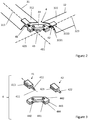
- the figures 2 and 3 illustrate details of the connectors 4 used by the blind illustrated by the figure 1 .
- the axes of rotation 411, 421 of the first and second fixing means 41, 42 thus form an angle 43 corresponding to the angle formed by the first and the second plane 110, 210, in particular to the angle formed by the axes of rotation 323 of the two strips retained by the same connector.
- the amplitude of this angle can range from 45 ° to 135 °.
- the angle 43 formed by the axes of rotation 411, 421 is substantially straight (i.e. 90 ° +/- 5).
- the first and second fixing means are configured to connect the two ends of the two strips by a connection to two axes of rotation, by means of two separate pivot or pivot-sliding connection.
- Each axis of rotation of the first and second attachment means is collinear with the axis of rotation 313, 323 of the retained strip.
- the axis of rotation of the fixing means of the angle connector corresponds to the axis of rotation of the guide means retaining axially (along its axis of rotation) the lamella to the longitudinal guide.
- the corner connector 4 illustrated by the figures 2 and 3 comprises a body 44.
- the first and second fixing means 41, 42 are individually connected to the body 44 by means of a pivot-sliding connection, advantageously by a pivot connection 411, 421, 440, 441.
- the corner connector can, by means of pivot connections, contribute to the control of undesirable lateral movements of the blinds, this alone or in combination with one or more lateral guides.
- Each fixing means 41, 42 comprises a bent portion 413, 423 and an elongated portion 412, 422, in particular having the form of a rod, a cylinder, a cone or a truncated cone.
- the bent portion 413, 423 is configured to retain a surface 3220, 3221 of the second end 312, 322 of the strip 31, 32, preferably by a bent U-shaped portion. This latter configuration makes it possible to retain the strip by its two surfaces opposite 3220, 3221, which facilitates its fixing as well as the robustness of the fixing by a larger contact surface.
- the bent portion 413, 423 can be mechanically connected to the orientable strip by a permanent mechanical assembly (in particular by gluing or welding) or advantageously removable (in particular by nailing, screwing, or riveting).
- the elongated portion 412, 422 is configured to be received by a cavity of the body 44 so as to form a pivot connection (or a sliding pivot connection) with the latter.
- the pivot or sliding pivot connection can be achieved by sliding the distant portion with corresponding surfaces of the cavity.
- the pivot link further comprises a mechanism for limiting the relative movements in translation between the elongated portion and the cavity along their axis of rotation, which can be achieved by stops and / or protuberant surfaces of the elongated portion and / or the cavity.
- a pivot connection can be achieved by means of one or more bearings (not shown) operating between the elongated portion and the cavity, in particular by a ball bearing operating between surfaces of the cavity and the elongated portion.
- the body 44 of the corner connector 4 is produced in two parts 443, 444, notably assemblable by means of screw element 442.
- Each of these parts partially delimits the cavities 440, 441 for receiving the fixing means 41 , 42 so as to allow installation of the fixing means in their housing before the assembly of the two parts of the body.
- This configuration allows not only an easy manufacture of the corner connectors, but also an easy installation of the stacks of blind slats.
- the control system 23-26 illustrated by the figure 1 comprises in particular a plurality of cords 50-53 operating on the radial ends of the strips and strips 54, 55 operating on the bottommost strip of each stack.
- the 23-26 control system is configured so as to allow the cords to operate in a coordinated manner on the lamellae of one or more of the stacks as well as to coordinate the movement of the strips 54, 55 in order to translate in a coordinated manner the lowest lamella of each stack .
- blind with a plurality of stackings Other expressions could also be used, for example referring to a plurality of synchronized blinds, each comprising a single stack.
- the proposed solution thus effectively protects two window openings forming any angle, in particular by allowing an independent inclination of each stack of strips, while completely freeing up the space of the openings when the blind is raised.
Landscapes
- Engineering & Computer Science (AREA)
- Structural Engineering (AREA)
- Architecture (AREA)
- Civil Engineering (AREA)
- Blinds (AREA)
Description
- La présente invention concerne un store à lamelles orientables.
- Les stores à lamelles sont communément utilisés en connexion avec des ouvertures vitrées de bâtiments d'habitation et professionnels, telles que des fenêtres, des lucarnes, des baies vitrées, et des porte-fenêtres, pour protéger les espaces d'intérieure de l'ensoleillement tout aussi bien que des regards indésirables.
- Un de plus grand défi dans ce domaine technologique est la proposition d'un store à lamelles s'adaptant efficacement à plusieurs typologies d'ouvertures vitrés, notamment en épousant les dimensions et la configuration spatiale de ces dernières, tout en garantissant la fonctionnalité initiale de ces ouvertures vitrées.
- Plusieurs solutions ont été proposées en poursuivant ce but. Par exemple, le document
US2631341A décrit un store dit Ventiane comprenant un dispositif de fixation murale permettant une inclinaison du store autour d'un axe horizontal afin de permettre son adaptation à un plus grand éventail de fenêtres ainsi que d'adapter le dégrée de protection souhaité. - En même temps, des nouvelles typologies d'ouvertures vitrées, notamment des compositions de plusieurs ouvertures vitrées adjacentes, ont fait leurs appariations dans des nombreux bâtiments. Ces compostions présent souvent un arrangement spatiale non-coplanaire et leur ouvertures vitrées sont fonctionnelles, c'est-à-dire elles permettent un passage d'air et/ou de personnes si souhaité, ce qui rend les solutions proposé obsolètes ou mal adaptées.
- Le document
CH707169A1 EP3431697A1 décrit un store à lamelles orientables comprenant deux empilements de lamelles et une pluralité de connecteurs d'angle de forme annulaire. - Un but de la présente invention est de proposer un store à lamelles exempt des limitations des stores connus, ou au moins réduisant les désavantages de ces derniers.
- Selon l'invention, ces buts sont atteints notamment au moyen du store à lamelles orientable selon la revendication 1.
- Cette solution présente notamment l'avantage par rapport à l'art antérieur de fournir une protection plus efficace à un arrangement de deux ou plus ouvertures vitrés adjacentes et verticales dont les surfaces ne sont pas coplanaires ou parallèles. Le store permet en effet une protection individuelle de chaque ouverture vitrée en permettant une orientation adaptée des lamelles de l'empilement la protégeant, ceci de manière indépendante des orientations des outres empilement de lamelles.
- Cette solution présente en outre l'avantage de garantir la fonctionnalité prévu initialement par chaque ouverture vitré de l'arrangement, car le store ne demande le placement d'une structure de support ou de guide entre les ouvertures vitrés qui pourrait entraver un mécanisme d'ouverture et/ou le libre passage d'air et de personnes.
- Des exemples de mise en œuvre de l'invention sont indiqués dans la description illustrée par les figures annexées dans lesquelles :
- la
figure 1 illustre un store à lamelles orientables selon l'invention; - les
figures 2 et 3 illustrent des détails du connecteur d'angle du store de lafigure 1 . - Aujourd'hui, il est commun de voir des nombreuses bâtiments d'habitations, publiques ou d'activité professionnels pourvu d'arrangements vitrés d'angle, notamment sous forme de baies vitrées, fenêtres ou porte-fenêtre verticale, dont les surfaces orientées à l'extérieur du bâtiment forment des angles droits, obtus ou aigus. Ces arrangements vitrés d'angle permettant généralement le passage d'air et, le cas échéant de personnes, car munis de dispositif d'ouvertures.
- La
figure 1 illustre un exemple d'un bâtiment comprenant deux baies vitrées 80, 81 adjacentes dont les surfaces externe forment un angle substantiellement droit (c'est-à-dire un ange de 90° +/- 5°). Au moins une des deux baies vitrées est muni d'un dispositif d'ouverture (pivotant et/ou coulissante) permettant le passage d'air ainsi que de personnes entre l'intérieure et l'extérieure du bâtiment. - La protection contre l'ensoleillement et les regards de ces typologies d'arrangements vitrés d'angle est communément proposé par le placement une pluralité de stores indépendants les uns des autres, ce qui dégrade non seulement l'esthétique du bâtiment mais qui entrave aussi la fonctionnalité de l'arrangement vitré.
- La demanderesse propose ainsi un store 1 à lamelles orientables permettant de protéger un arrangement vitré d'angle formé par au moins deux vitres plates 80, 81 et verticales contre le rayonnement solaire ainsi que des regards indésirables par un store 1, tout en garantissant la fonctionnalité initiale de l'arrangement d'angle.
- Le store 1 comprend une pluralité d'empilements 21, 22 de lamelles orientables, chaque empilement de store fournissant une protection à une des surfaces plates vitrées de l'arrangement vitré d'angle 80, 81.
- Chaque empilement 21, 22 comprend une même pluralité de lamelles orientables ayant un axe de rotation 313, 323 situé dans un plan 210, 220. Ce plan est substantiellement parallèle à la surface externe de l'élément de l'arrangement vitré d'angle 80, 81 qu'il protège et il est ainsi généralement vertical (c'est-à-dire parallèle à l'orientation de la pesanteur).
- Le store 1 comprend des guides longitudinaux 110,120, avantageusement positionnés aux extrémités latérales et opposées du store. Chaque guide a un axe 111,121 longitudinal et les axes des guides longitudinaux sont parallèles l'un à l'autre de sorte à pouvoir guider une extrémité 311, 312 de chaque lamelles des empilements situés sur les côtés du store.
- Les guides longitudinaux peuvent être des câbles de guidage, des rails de guidages, et/ou des profilées 11, 12 ayant (délimitant) des cavités longitudinales, ou une combinaison de ces derniers. Le guide longitudinal est fixé et/ou retenu à une infrastructure généralement fixe et permanente du bâtiment.
- L'autre extrémité des lamelles de ces empilements latéraux, ainsi que les extrémités de lamelles d'empilements de lamelles placés entre les deux empilements latéraux, sont reliées entre eux par des connecteurs d'angle 4.
- Chaque connecteur d'angle comprend:
- un premier moyen de fixation 41 retenant de manière rotative une extrémité 312 d'une lamelle par son axe de rotation 313, et
- un deuxième moyen de fixation 42 retenant de manière rotative une extrémité 322 d'une autre lamelle 32 d'un empilement adjacente par son axe de rotation 323.
- Le premier et le deuxième moyen de fixation sont (conjointement) configurés de sorte à relier les deux lamelles par une liaison rotule.
- Alternativement, le premier et le deuxième moyen de fixation sont configurés pour relier les deux lamelles par une liaison à deux axes de rotations, par moyen de deux liaison pivots, par deux liaisons pivot-glissants ou par une combinaison des deux.
- Le store 1 permet ainsi de protéger efficacement deux ouvertures vitrées formant un quelconque angle, ainsi que des arrangements d'angle formé par plus que deux ouvertures vitres formant ainsi des arrangements spatiaux plus complexes, contre le rayonnement solaire et les regards indiscrets. Le store proposé permet de régler indépendamment l'inclinaison (orientation) des lamelles de chaque empilement de sorte à s'adapter et prendre en compte les conditions d'ensoleillement et d'intimité découlant de l'emplacement de chaque ouverture vitrée de l'arrangement d'angle.
- Avantageusement, le store à lamelles orientables 1 comprend en outre un système de commande 23-26 manuel, semi-automatique ou automatique pour l'orientation (inclinaison) angulaire des lamelles de chaque empilement autour de leur axe de rotation 313, ceci de manière indépendante de l'orientation des lamelles des autres empilements.
- Le système de commande 23-26 est en outre configuré pour translater conjointement la lamelle la plus en bas de chaque empilement le long des guides de sorte à descendre et à remonter les lamelles du store.
- Le système de commande 23-26 peut être ainsi équipé d'une pluralité de cordelettes 50-53 opérantes sur des extrémités radiales des lamelles, une ou plusieurs bandes 54-55 et/ou un train de remontage opérantes sur la lamelle la plus en bas de chaque empilement.
- Dans l'exemple de la
figure 1 , l'arrangement vitré d'angle 80, 81 est formé par deux baies vitrées 80, 81 adjacentes et verticales, dont les surfaces externe forment un angle substantiellement droit. - Le store 1 de la
figure 1 comprend ainsi : - un premier empilement 21 de lamelles orientables ayant un axe de rotation 313 situé dans un premier plan 210; une première extrémité 311 de ces lamelles étant guidée par un premier guide 110; et
- un deuxième empilement 22 de lamelles orientables ayant un axe de rotation 323 situé dans un deuxième plan 220 incident au premier plan 210, notamment perpendiculaire au premier plan; une première extrémité 321 de ces lamelles étant guidée par une deuxième guide 120.
- Par plans incidents on entend deux plans dont l'intersection prend la forme d'une ligne, notamment deux plans non-coplanaires et se croisant l'un avec l'autre.
- L'axe de rotation 313 des lamelles orientables du premier plan et l'axe de rotation 323 des lamelles orientables du deuxième plan forment un angle se situant dans un intervalle de 45° à 135°, notamment de 90°.
- Chaque guide longitudinal de la
figure 1 est un profilé 11, 12 ayant et/ou délimitant une cavité longitudinale, profilé qui est fixé à une infrastructure fixe et permanente du bâtiment. - Chaque premier extrémité des lamelles orientables du premier et/ou du deuxième plan peut comprendre un moyen de guidage (connecteur, goupille, élément de guidage, raccord, etc) coopérant avec une des guides 11, 12 de sorte à retenir axialement (longitudinalement) la lamelle au premier ou deuxième guide longitudinal, ce moyen de guidage fournissant, assurant et/ou permettant une rotation de la lamelle selon son (ledit) axe de rotation 313, 323.
- Dans le mode de réalisation de la
figure 1 , chaque première extrémité des lamelles orientables du premier et du deuxième plan comprend un moyen de guidage coopérant avec l'un des guides longitudinaux. Le moyen de guidage est relié mécaniquement au guide de sorte à créer une liaison pivot-glissant avec le guide, cette liaison permettant de retenir axialement la lamelle, tout en fournissant, assurant et/ou permettant sa rotation autour dudit axe de rotation 313, 323 - Le moyen de guidage de la réalisation de la
figure 1 comprend une protubérance configurée pour se loger dans la cavité longitudinale du profilé (c.à.d. dans volume délimité par le profilé) de sorte à réaliser ladite liaison pivot-glissant, notamment par une portion rotative de l'extrémité ou par une surface cylindrique de la protubérance coopérante avec les parois latérales du profilé. - Le store 1 comprend ensuite une pluralité de connecteurs d'angle 4. Les
figures 2 et 3 illustrent des détails des connecteurs 4 utilisé par le store illustré par lafigure 1 . - Chacun de ces connecteurs 4 comprend:
- un premier moyen de fixation 41 retenant de manière rotative une deuxième extrémité 312 d'une lamelle 31 du premier empilement par son axe de rotation 313; et
- un deuxième moyen de fixation 42 retenant de manière rotative une deuxième extrémité 322 d'une lamelle 32 du deuxième empilement par son axe de rotation 323.
- Les axes de rotation 411, 421 du premier et du deuxième moyen de fixation 41, 42 forment ainsi un angle 43 correspondant à l'angle formé par le premier et le deuxième plan 110,210, notamment à l'angle formé par les axes de rotation 323 des deux lamelles retenues par le même connecteur. Selon la typologie de la configuration vitrées d'angle à protéger, l'amplitude de cet angle peut se situé dans un intervalle de 45° à 135°. Dans le cas illustré, l'angle 43 formé par les axes de rotation 411, 421 est substantiellement droit (c.-à-d. 90° +/- 5).
- Le premier et le deuxième moyen de fixation sont configurés pour relier les deux extrémités des deux lamelles par une liaison à deux axes de rotations, par moyen de deux distinct liaison pivots ou pivot-glissants. Chaque axe de rotation du premier et le deuxième moyen de fixation est colinéaire à l'axe de rotation 313, 323 de la lamelle retenue.
- Notamment en cas d'une lamelle guidée par la première ou deuxième guide longitudinal, l'axe de rotation du moyen de fixation du connecteur d'angle corresponde à l'axe de rotation du moyen de guidage retenant axialement (le long de son axe de rotation) la lamelle au guide longitudinal.
- Le connecteur d'angle 4 illustré par les
figures 2 et 3 comprend un corps 44. Le premier et le deuxième moyen de fixation 41, 42 sont reliés individuellement au corps 44 par moyen d'une liaison pivot-glissant, avantageusement par une liaison pivot 411, 421, 440, 441. Le connecteur d'angle peut, par moyen de liaisons pivot, contribuer au contrôle des mouvements latéraux indésirables des stores, ceci seul ou en combinaison avec une ou plusieurs guides latérales. - Chaque moyen de fixation 41, 42 comprend une portion coudée 413, 423 et une portion allongée 412, 422, notamment ayant forme d'une tige, d'un cylindre, d'un cône ou d'un tronc de cône.
- La portion coudée 413, 423 est configurée pour retenir une surface 3220, 3221 de la deuxième extrémité 312, 322 de la lamelle 31, 32, de préférence par une portion coudée en U. Cette dernière configuration permet de retenir la lamelle par ses deux surfaces opposées 3220, 3221, ce qui facilite son fixations ainsi que la robustesse de la fixation par une plus grande surface de contact. La portion coudée 413, 423 peut être relié mécaniquement à la lamelle orientable par un assemblage mécanique permanent (notamment par collage ou soudage) ou avantageusement démontable (notamment par clouage, vissage, ou rivetage).
- La portion allongée 412, 422 est configuré pour être reçue par une cavité du corps 44 de sorte à former une liaison pivot (ou une liaison pivot glissant) avec ce dernier. La liaison pivot ou pivot glissant peut se réaliser par glissement de la portion éloigné avec des surface correspondent de la cavité. La liaison pivot comprend en outre un mécanisme de limitation des mouvements relatifs en translation entre la portion allongée et la cavité selon leur axe de rotation, qui peut se réaliser par des butées et/ou des surfaces protubérantes de la portion allongée et/ou de la cavité.
- Alternativement, une liaison pivot peut se réaliser par l'intermédiaire d'un ou plusieurs roulements (non illustré) opérantes entre la portion allongée et la cavité, notamment par un roulement à billes opérant entre des surfaces de la cavité et de la portion allongée.
- Avantageusement, le corps 44 du connecteur d'angle 4 est réalisé en deux pièces 443, 444, assemblable notablement par moyens d'élément de visserie 442. Chacun de ces pièce délimite en partie les cavités 440, 441 de réception des moyen de fixation 41, 42 de sorte à permettre une installation des moyen de fixation dans leur logement avant l'assemblage des deux pièces du corps.
- Cette configuration permet, non seulement une fabrication aisée des connecteurs d'angle, mais aussi une installation aisée des empilements de lamelles du store.
- Le store à lamelles orientables 1 comprend en outre un système de commande 23-26 configuré pour:
- orienter angulairement les lamelles du premier empilement 21 autour de leur axe de rotation 313 de manière indépendante de l'orientation des lamelles du deuxième empilement 22, et pour
- orienter angulairement les lamelles du deuxième empilement 22 autour de leur axes de rotation 323 de manière indépendante de l'orientation des lamelles du premier empilement 21.
- Le système de commande 23-26 illustré par la
figure 1 comprend notamment une pluralité de cordelettes 50-53 opérantes sur des extrémités radiales des lamelles et des bandes 54, 55 opérantes sur la lamelle la plus en bas de chaque empilement. Le système de commande 23-26 est configuré de sorte à permettre aux cordelettes d'opérer de manière coordonnée sur les lamelles d'un ou de plusieurs des empilements ainsi qu'à coordonner le mouvement des bandes 54, 55 afin de translater de manière coordonnée la lamelle la plus en bas de chaque empilement. - Dans ce document l'invention est décrite et revendiquée par l'expression "store avec une pluralité de empilement" On pourrait également utiliser d'autres expressions, par exemple se référant à une pluralité de stores synchronisées, chacune comportant un seul empilement.
- La solution proposée permet ainsi de protéger efficacement deux ouvertures vitres formant un quelconque angle notamment en permettant une inclinaison indépendantes de chaque empilement de lamelles, tout en libérant complètement l'espace des ouvertures lorsque le store est remonté.
-
- 1
- Store à lamelles
- 11,12
- Profilé
- 110,120
- Guide
- 111,121
- Axe longitudinale du guide
- 21,22
- Empilement de lamelles
- 210,220
- Plan
- 31,32
- lamelle orientable
- 311,312,321,322
- Extrémités
- 3220,3221
- Surfaces
- 313,323
- Axe de rotation
- 4
- Connecteurs d'angle
- 41,42
- Pince de rétention
- 411,421
- Axe de rotation
- 412,422
- Tige
- 413,423
- Portion en U
- 43
- Angle du store
- 44
- Corps
- 440,441
- Cavité
- 442
- Vis/écrou
- 443, 444
- Pièce du corps
- 50-53
- Cordelette
- 54,55
- Bande
- 80,81
- Vitre
Claims (9)
- Store à lamelles orientables (1), comprenant:un premier et avantageusement un deuxième guide longitudinal (110,120) ayant chacun un axe (111,121) longitudinal, les axes des deux guides longitudinaux étant parallèles l'un à l'autre;un premier empilement (21) de lamelles orientables ayant un axe de rotation (313) situé dans un premier plan (210), une première extrémité (311) de ces lamelles étant guidée par le premier guide (110);un deuxième empilement (22) de lamelles orientables ayant un axe de rotation (323) situé dans un deuxième plan (220) incident au premier plan (210), avantageusement une première extrémité (321) de ces lamelles étant guidée par le deuxième guide (120);une pluralité de connecteurs d'angle (4), chaque connecteur d'angle comprenant:un premier moyen de fixation (41) retenant de manière rotative une deuxième extrémité (312) d'une lamelle (31) du premier empilement par son axe de rotation (313); etun deuxième moyen de fixation (42) retenant de manière rotative une deuxième extrémité (322) d'une lamelle (32) du deuxième empilement par son axe de rotation (323) ;
dans lequel :le premier et deuxième moyen de fixation (41, 42) opèrent entre lesdites deuxième extrémités (312, 322) de sorte à former une liaison rotule; ouau moins un desdits connecteurs d'angle (4) comprend un corps (44), le premier et deuxième moyen de fixation (41, 42) dudit au moins un desdits connecteurs d'angle (4) étant relié mécaniquement au corps (44) par moyen d'une liaison pivot (411, 421, 440, 441) ou pivot-glissant;caractérisé en ce que les axes de rotation (411, 421) du premier et du deuxième moyen de fixation (41, 42) forment un angle (43) ayant une amplitude située dans un intervalle de 45° à 135°, de préférence un angle (43) de 90° +/- 5°. - Store à lamelles orientables (1) selon la revendication 1, ladite liaison pivot ou pivot glissante comprenant une portion allongée (412, 422) ainsi qu'une cavité de rotation (440, 441) pour recevoir cette portion allongée; préférablement ladite portion allongée étant part du premier et/ou deuxième moyen de fixation (41, 42), et ladite cavité de rotation étant part dudit corps (44) dudit au moins un desdits connecteurs d'angle (4).
- Store à lamelles orientables (1) selon la revendication 2, dans lequel
ladite portion allongée (412, 422) est pourvue d'une section circulaire et la cavité de rotation (440, 441) comprend une paroi interne de section circulaire équivalente de sorte à permettre une rotation relative entre la portion allongée et la cavité de rotation. - Store à lamelles orientables (1) selon la revendication 2, dans lequel
la liaison pivot comprend un roulement opérant entre ladite portion allongée (412, 422) et ladite cavité de rotation (440, 441) de sorte à permettre une rotation relative entre la portion allongée et la cavité de rotation. - Store à lamelles orientables (1) selon l'une des revendications 1 à 4, dans lequel
le premier et/ou deuxième moyen de fixation comprend une portion coudée configurée pour retenir une surface (3220, 3221) de la deuxième extrémité (312, 322) de la lamelle (31, 32);
de préférence la portion coudée étant une portion en U configurée pour retenir deux surfaces opposées (3220, 3221) de la deuxième extrémité (312, 322) de la lamelle (31, 32). - Store à lamelles orientables (1) selon l'une des revendications 1 à 5, comprenant en outre un système de commande (50-55) configuré pour:orienter angulairement les lamelles du premier empilement (21) autour de leur axe de rotation (313) de manière indépendante de l'orientation des lamelles du deuxième empilement (22), et/ouorienter angulairement les lamelles du deuxième empilement (22) autour de leur axes de rotation (323) de manière indépendante de l'orientation des lamelles du premier empilement (21);de préférence le système de commande comprenant un ou plusieurs cordelettes (50-53) opérantes sur des extrémités radiales des lamelles.
- Store à lamelles orientables (1) selon l'une des revendications 1 à 6, dans lequel
le système de commande (50-55) est configuré pour déplacer conjointement la lamelle la plus en bas du premier et du deuxième empilement (21, 22) le long du premier et du deuxième guide (110, 120). - Store à lamelles orientables (1) selon l'une des revendications 1 à 7, dans lequel
le premier et/ou deuxième guide longitudinal est un câble de guidage. - Store à lamelles orientables (1) selon l'une des revendications 1 à 8, dans lequel
le premier et/ou deuxième guide longitudinal comprend une cavité longitudinale (120, 121) d'un premier et/ou d'un deuxième profilé (11, 12).
Applications Claiming Priority (1)
| Application Number | Priority Date | Filing Date | Title |
|---|---|---|---|
| CH01188/17A CH714197A2 (fr) | 2017-09-28 | 2017-09-28 | Store à lamelles orientables. |
Publications (2)
| Publication Number | Publication Date |
|---|---|
| EP3461986A1 EP3461986A1 (fr) | 2019-04-03 |
| EP3461986B1 true EP3461986B1 (fr) | 2020-03-25 |
Family
ID=63713664
Family Applications (1)
| Application Number | Title | Priority Date | Filing Date |
|---|---|---|---|
| EP18197604.4A Active EP3461986B1 (fr) | 2017-09-28 | 2018-09-28 | Store à lamelles orientables |
Country Status (2)
| Country | Link |
|---|---|
| EP (1) | EP3461986B1 (fr) |
| CH (1) | CH714197A2 (fr) |
Families Citing this family (1)
| Publication number | Priority date | Publication date | Assignee | Title |
|---|---|---|---|---|
| CN111236819A (zh) * | 2020-01-09 | 2020-06-05 | 北京伟业窗饰遮阳帘有限公司 | 一种直角电动蜂巢帘 |
Citations (3)
| Publication number | Priority date | Publication date | Assignee | Title |
|---|---|---|---|---|
| DE2651873A1 (de) | 1976-11-13 | 1978-05-18 | Hueppe Justin Fa | Rafflamellenjalousie mit seitenfuehrungsschienen |
| CH707169A1 (de) | 2012-11-09 | 2014-05-15 | Beat Guhl | Führungsschienenanordnung für einen Behang. |
| EP3431697A1 (fr) * | 2017-07-17 | 2019-01-23 | Keller Ag | Dispositif d'ombrage |
Family Cites Families (1)
| Publication number | Priority date | Publication date | Assignee | Title |
|---|---|---|---|---|
| US2631341A (en) | 1949-03-21 | 1953-03-17 | Rhode Island Engineering And M | Adjustable blind or awning |
-
2017
- 2017-09-28 CH CH01188/17A patent/CH714197A2/fr unknown
-
2018
- 2018-09-28 EP EP18197604.4A patent/EP3461986B1/fr active Active
Patent Citations (3)
| Publication number | Priority date | Publication date | Assignee | Title |
|---|---|---|---|---|
| DE2651873A1 (de) | 1976-11-13 | 1978-05-18 | Hueppe Justin Fa | Rafflamellenjalousie mit seitenfuehrungsschienen |
| CH707169A1 (de) | 2012-11-09 | 2014-05-15 | Beat Guhl | Führungsschienenanordnung für einen Behang. |
| EP3431697A1 (fr) * | 2017-07-17 | 2019-01-23 | Keller Ag | Dispositif d'ombrage |
Also Published As
| Publication number | Publication date |
|---|---|
| CH714197A2 (fr) | 2019-03-29 |
| EP3461986A1 (fr) | 2019-04-03 |
Similar Documents
| Publication | Publication Date | Title |
|---|---|---|
| EP2862259B1 (fr) | Dispositif motorise de manoeuvre destine a la manoeuvre d'un ecran mobile a toile enroulable d'un dispositif de couverture de fenetre ou d'ecran de projection | |
| EP1741872B1 (fr) | Système de volet roulant encastrable et non apparent | |
| EP3461986B1 (fr) | Store à lamelles orientables | |
| EP2844817B1 (fr) | Installation de fermeture ou de protection solaire, et procede de mise en oeuvre d'une telle installation | |
| EP2927536B1 (fr) | Actionneur linéaire et dispositif d'occultation associé | |
| EP3085871B1 (fr) | Vitrage, profile adapte au vitrage et ouvrant comprenant un tel vitrage | |
| FR2831932A1 (fr) | Dispositif de liaison mecanique pour systeme d'attache d'elements sur une structure | |
| WO2012080386A1 (fr) | Mecanisme de rotation des lames d'un volet roulant | |
| FR3023575A1 (fr) | Coffre-tunnel, demi-coffre, pourvu d'une gouttiere pour receptionner un second occultant | |
| EP1644607B1 (fr) | Porte a repliement et dispositif de guidage de rideau | |
| EP3623565A1 (fr) | Dispositif de fermeture ou d'occultation pour une construction | |
| EP2942472B1 (fr) | Dispositif de fermeture de type store, volet roulant ou similaire notamment pour fenêtre de toit | |
| EP2886761A2 (fr) | Dispositif de fermeture pour une embrasure d'un batiment | |
| EP3173564A1 (fr) | Châssis pour volet battant | |
| EP3623564B1 (fr) | Dispositif de fermeture ou d'occultation avec tablier et système anti-effraction | |
| FR2495205A1 (fr) | Structure ajustable a pivotement pour supporter les charpentes de toitures | |
| EP3585969B1 (fr) | Volet coulissant a montage simple et rapide | |
| CA1274420A (fr) | Dispositif adaptable au cadre d'une fenetre | |
| FR3146919A3 (fr) | Appareil de couverture | |
| EP3059376A1 (fr) | Procédé d'assemblage d'une installation de fermeture ou de protection solaire, système de support et installation | |
| FR3113207A1 (fr) | Boîtier d’alimentation de secours d’un actionneur électromécanique d’une installation de fermeture, d’occultation ou de protection solaire, caisson comprenant un tel boîtier et installation comprenant un tel caisson | |
| FR2783864A1 (fr) | Ensemble caisson pour volet roulant notamment | |
| FR3147578A3 (fr) | Système d’assemblage d’un tube enrouleur sur une structure porteuse d’une construction de type pergola et construction comprenant un tel système | |
| EP4223950A1 (fr) | Procédé de montage d'une pièce | |
| WO1997000368A1 (fr) | Brise-soleil pouvant etre integre dans un double vitrage |
Legal Events
| Date | Code | Title | Description |
|---|---|---|---|
| PUAI | Public reference made under article 153(3) epc to a published international application that has entered the european phase |
Free format text: ORIGINAL CODE: 0009012 |
|
| STAA | Information on the status of an ep patent application or granted ep patent |
Free format text: STATUS: THE APPLICATION HAS BEEN PUBLISHED |
|
| AK | Designated contracting states |
Kind code of ref document: A1 Designated state(s): AL AT BE BG CH CY CZ DE DK EE ES FI FR GB GR HR HU IE IS IT LI LT LU LV MC MK MT NL NO PL PT RO RS SE SI SK SM TR |
|
| AX | Request for extension of the european patent |
Extension state: BA ME |
|
| STAA | Information on the status of an ep patent application or granted ep patent |
Free format text: STATUS: REQUEST FOR EXAMINATION WAS MADE |
|
| 17P | Request for examination filed |
Effective date: 20190722 |
|
| RBV | Designated contracting states (corrected) |
Designated state(s): AL AT BE BG CH CY CZ DE DK EE ES FI FR GB GR HR HU IE IS IT LI LT LU LV MC MK MT NL NO PL PT RO RS SE SI SK SM TR |
|
| GRAP | Despatch of communication of intention to grant a patent |
Free format text: ORIGINAL CODE: EPIDOSNIGR1 |
|
| STAA | Information on the status of an ep patent application or granted ep patent |
Free format text: STATUS: GRANT OF PATENT IS INTENDED |
|
| INTG | Intention to grant announced |
Effective date: 20191017 |
|
| GRAJ | Information related to disapproval of communication of intention to grant by the applicant or resumption of examination proceedings by the epo deleted |
Free format text: ORIGINAL CODE: EPIDOSDIGR1 |
|
| STAA | Information on the status of an ep patent application or granted ep patent |
Free format text: STATUS: REQUEST FOR EXAMINATION WAS MADE |
|
| GRAS | Grant fee paid |
Free format text: ORIGINAL CODE: EPIDOSNIGR3 |
|
| STAA | Information on the status of an ep patent application or granted ep patent |
Free format text: STATUS: GRANT OF PATENT IS INTENDED |
|
| GRAP | Despatch of communication of intention to grant a patent |
Free format text: ORIGINAL CODE: EPIDOSNIGR1 |
|
| GRAA | (expected) grant |
Free format text: ORIGINAL CODE: 0009210 |
|
| STAA | Information on the status of an ep patent application or granted ep patent |
Free format text: STATUS: THE PATENT HAS BEEN GRANTED |
|
| INTC | Intention to grant announced (deleted) | ||
| INTG | Intention to grant announced |
Effective date: 20200211 |
|
| AK | Designated contracting states |
Kind code of ref document: B1 Designated state(s): AL AT BE BG CH CY CZ DE DK EE ES FI FR GB GR HR HU IE IS IT LI LT LU LV MC MK MT NL NO PL PT RO RS SE SI SK SM TR |
|
| REG | Reference to a national code |
Ref country code: GB Ref legal event code: FG4D Free format text: NOT ENGLISH |
|
| REG | Reference to a national code |
Ref country code: AT Ref legal event code: REF Ref document number: 1248762 Country of ref document: AT Kind code of ref document: T Effective date: 20200415 Ref country code: IE Ref legal event code: FG4D Free format text: LANGUAGE OF EP DOCUMENT: FRENCH |
|
| REG | Reference to a national code |
Ref country code: DE Ref legal event code: R096 Ref document number: 602018003268 Country of ref document: DE |
|
| REG | Reference to a national code |
Ref country code: CH Ref legal event code: NV Representative=s name: P&TS SA, CH |
|
| PG25 | Lapsed in a contracting state [announced via postgrant information from national office to epo] |
Ref country code: FI Free format text: LAPSE BECAUSE OF FAILURE TO SUBMIT A TRANSLATION OF THE DESCRIPTION OR TO PAY THE FEE WITHIN THE PRESCRIBED TIME-LIMIT Effective date: 20200325 Ref country code: RS Free format text: LAPSE BECAUSE OF FAILURE TO SUBMIT A TRANSLATION OF THE DESCRIPTION OR TO PAY THE FEE WITHIN THE PRESCRIBED TIME-LIMIT Effective date: 20200325 Ref country code: NO Free format text: LAPSE BECAUSE OF FAILURE TO SUBMIT A TRANSLATION OF THE DESCRIPTION OR TO PAY THE FEE WITHIN THE PRESCRIBED TIME-LIMIT Effective date: 20200625 |
|
| PG25 | Lapsed in a contracting state [announced via postgrant information from national office to epo] |
Ref country code: GR Free format text: LAPSE BECAUSE OF FAILURE TO SUBMIT A TRANSLATION OF THE DESCRIPTION OR TO PAY THE FEE WITHIN THE PRESCRIBED TIME-LIMIT Effective date: 20200626 Ref country code: BG Free format text: LAPSE BECAUSE OF FAILURE TO SUBMIT A TRANSLATION OF THE DESCRIPTION OR TO PAY THE FEE WITHIN THE PRESCRIBED TIME-LIMIT Effective date: 20200625 Ref country code: HR Free format text: LAPSE BECAUSE OF FAILURE TO SUBMIT A TRANSLATION OF THE DESCRIPTION OR TO PAY THE FEE WITHIN THE PRESCRIBED TIME-LIMIT Effective date: 20200325 Ref country code: LV Free format text: LAPSE BECAUSE OF FAILURE TO SUBMIT A TRANSLATION OF THE DESCRIPTION OR TO PAY THE FEE WITHIN THE PRESCRIBED TIME-LIMIT Effective date: 20200325 Ref country code: SE Free format text: LAPSE BECAUSE OF FAILURE TO SUBMIT A TRANSLATION OF THE DESCRIPTION OR TO PAY THE FEE WITHIN THE PRESCRIBED TIME-LIMIT Effective date: 20200325 |
|
| REG | Reference to a national code |
Ref country code: NL Ref legal event code: MP Effective date: 20200325 |
|
| REG | Reference to a national code |
Ref country code: LT Ref legal event code: MG4D |
|
| PG25 | Lapsed in a contracting state [announced via postgrant information from national office to epo] |
Ref country code: NL Free format text: LAPSE BECAUSE OF FAILURE TO SUBMIT A TRANSLATION OF THE DESCRIPTION OR TO PAY THE FEE WITHIN THE PRESCRIBED TIME-LIMIT Effective date: 20200325 |
|
| PG25 | Lapsed in a contracting state [announced via postgrant information from national office to epo] |
Ref country code: IS Free format text: LAPSE BECAUSE OF FAILURE TO SUBMIT A TRANSLATION OF THE DESCRIPTION OR TO PAY THE FEE WITHIN THE PRESCRIBED TIME-LIMIT Effective date: 20200725 Ref country code: RO Free format text: LAPSE BECAUSE OF FAILURE TO SUBMIT A TRANSLATION OF THE DESCRIPTION OR TO PAY THE FEE WITHIN THE PRESCRIBED TIME-LIMIT Effective date: 20200325 Ref country code: SM Free format text: LAPSE BECAUSE OF FAILURE TO SUBMIT A TRANSLATION OF THE DESCRIPTION OR TO PAY THE FEE WITHIN THE PRESCRIBED TIME-LIMIT Effective date: 20200325 Ref country code: EE Free format text: LAPSE BECAUSE OF FAILURE TO SUBMIT A TRANSLATION OF THE DESCRIPTION OR TO PAY THE FEE WITHIN THE PRESCRIBED TIME-LIMIT Effective date: 20200325 Ref country code: LT Free format text: LAPSE BECAUSE OF FAILURE TO SUBMIT A TRANSLATION OF THE DESCRIPTION OR TO PAY THE FEE WITHIN THE PRESCRIBED TIME-LIMIT Effective date: 20200325 Ref country code: SK Free format text: LAPSE BECAUSE OF FAILURE TO SUBMIT A TRANSLATION OF THE DESCRIPTION OR TO PAY THE FEE WITHIN THE PRESCRIBED TIME-LIMIT Effective date: 20200325 Ref country code: PT Free format text: LAPSE BECAUSE OF FAILURE TO SUBMIT A TRANSLATION OF THE DESCRIPTION OR TO PAY THE FEE WITHIN THE PRESCRIBED TIME-LIMIT Effective date: 20200818 |
|
| REG | Reference to a national code |
Ref country code: DE Ref legal event code: R026 Ref document number: 602018003268 Country of ref document: DE |
|
| PLBI | Opposition filed |
Free format text: ORIGINAL CODE: 0009260 |
|
| PLAX | Notice of opposition and request to file observation + time limit sent |
Free format text: ORIGINAL CODE: EPIDOSNOBS2 |
|
| PG25 | Lapsed in a contracting state [announced via postgrant information from national office to epo] |
Ref country code: DK Free format text: LAPSE BECAUSE OF FAILURE TO SUBMIT A TRANSLATION OF THE DESCRIPTION OR TO PAY THE FEE WITHIN THE PRESCRIBED TIME-LIMIT Effective date: 20200325 Ref country code: ES Free format text: LAPSE BECAUSE OF FAILURE TO SUBMIT A TRANSLATION OF THE DESCRIPTION OR TO PAY THE FEE WITHIN THE PRESCRIBED TIME-LIMIT Effective date: 20200325 |
|
| 26 | Opposition filed |
Opponent name: ALUKON KG Effective date: 20201228 |
|
| PG25 | Lapsed in a contracting state [announced via postgrant information from national office to epo] |
Ref country code: PL Free format text: LAPSE BECAUSE OF FAILURE TO SUBMIT A TRANSLATION OF THE DESCRIPTION OR TO PAY THE FEE WITHIN THE PRESCRIBED TIME-LIMIT Effective date: 20200325 |
|
| PLBB | Reply of patent proprietor to notice(s) of opposition received |
Free format text: ORIGINAL CODE: EPIDOSNOBS3 |
|
| PG25 | Lapsed in a contracting state [announced via postgrant information from national office to epo] |
Ref country code: SI Free format text: LAPSE BECAUSE OF FAILURE TO SUBMIT A TRANSLATION OF THE DESCRIPTION OR TO PAY THE FEE WITHIN THE PRESCRIBED TIME-LIMIT Effective date: 20200325 |
|
| REG | Reference to a national code |
Ref country code: BE Ref legal event code: MM Effective date: 20200930 |
|
| PG25 | Lapsed in a contracting state [announced via postgrant information from national office to epo] |
Ref country code: LU Free format text: LAPSE BECAUSE OF NON-PAYMENT OF DUE FEES Effective date: 20200928 |
|
| PG25 | Lapsed in a contracting state [announced via postgrant information from national office to epo] |
Ref country code: IE Free format text: LAPSE BECAUSE OF NON-PAYMENT OF DUE FEES Effective date: 20200928 Ref country code: BE Free format text: LAPSE BECAUSE OF NON-PAYMENT OF DUE FEES Effective date: 20200930 |
|
| PG25 | Lapsed in a contracting state [announced via postgrant information from national office to epo] |
Ref country code: TR Free format text: LAPSE BECAUSE OF FAILURE TO SUBMIT A TRANSLATION OF THE DESCRIPTION OR TO PAY THE FEE WITHIN THE PRESCRIBED TIME-LIMIT Effective date: 20200325 Ref country code: MT Free format text: LAPSE BECAUSE OF FAILURE TO SUBMIT A TRANSLATION OF THE DESCRIPTION OR TO PAY THE FEE WITHIN THE PRESCRIBED TIME-LIMIT Effective date: 20200325 Ref country code: CY Free format text: LAPSE BECAUSE OF FAILURE TO SUBMIT A TRANSLATION OF THE DESCRIPTION OR TO PAY THE FEE WITHIN THE PRESCRIBED TIME-LIMIT Effective date: 20200325 |
|
| PG25 | Lapsed in a contracting state [announced via postgrant information from national office to epo] |
Ref country code: MK Free format text: LAPSE BECAUSE OF FAILURE TO SUBMIT A TRANSLATION OF THE DESCRIPTION OR TO PAY THE FEE WITHIN THE PRESCRIBED TIME-LIMIT Effective date: 20200325 Ref country code: MC Free format text: LAPSE BECAUSE OF FAILURE TO SUBMIT A TRANSLATION OF THE DESCRIPTION OR TO PAY THE FEE WITHIN THE PRESCRIBED TIME-LIMIT Effective date: 20200325 Ref country code: AL Free format text: LAPSE BECAUSE OF FAILURE TO SUBMIT A TRANSLATION OF THE DESCRIPTION OR TO PAY THE FEE WITHIN THE PRESCRIBED TIME-LIMIT Effective date: 20200325 |
|
| REG | Reference to a national code |
Ref country code: AT Ref legal event code: UEP Ref document number: 1248762 Country of ref document: AT Kind code of ref document: T Effective date: 20200325 |
|
| PLCK | Communication despatched that opposition was rejected |
Free format text: ORIGINAL CODE: EPIDOSNREJ1 |
|
| APBM | Appeal reference recorded |
Free format text: ORIGINAL CODE: EPIDOSNREFNO |
|
| APBP | Date of receipt of notice of appeal recorded |
Free format text: ORIGINAL CODE: EPIDOSNNOA2O |
|
| APAH | Appeal reference modified |
Free format text: ORIGINAL CODE: EPIDOSCREFNO |
|
| APBQ | Date of receipt of statement of grounds of appeal recorded |
Free format text: ORIGINAL CODE: EPIDOSNNOA3O |
|
| GBPC | Gb: european patent ceased through non-payment of renewal fee |
Effective date: 20220928 |
|
| PG25 | Lapsed in a contracting state [announced via postgrant information from national office to epo] |
Ref country code: GB Free format text: LAPSE BECAUSE OF NON-PAYMENT OF DUE FEES Effective date: 20220928 |
|
| PGFP | Annual fee paid to national office [announced via postgrant information from national office to epo] |
Ref country code: CZ Payment date: 20230918 Year of fee payment: 6 Ref country code: AT Payment date: 20230921 Year of fee payment: 6 |
|
| PGFP | Annual fee paid to national office [announced via postgrant information from national office to epo] |
Ref country code: IT Payment date: 20230927 Year of fee payment: 6 Ref country code: CH Payment date: 20231001 Year of fee payment: 6 |
|
| PGFP | Annual fee paid to national office [announced via postgrant information from national office to epo] |
Ref country code: DE Payment date: 20240918 Year of fee payment: 7 |
|
| PGFP | Annual fee paid to national office [announced via postgrant information from national office to epo] |
Ref country code: FR Payment date: 20240925 Year of fee payment: 7 |