EP3461602A1 - Pale fixe et procédé de fabrication - Google Patents
Pale fixe et procédé de fabrication Download PDFInfo
- Publication number
- EP3461602A1 EP3461602A1 EP17194280.8A EP17194280A EP3461602A1 EP 3461602 A1 EP3461602 A1 EP 3461602A1 EP 17194280 A EP17194280 A EP 17194280A EP 3461602 A1 EP3461602 A1 EP 3461602A1
- Authority
- EP
- European Patent Office
- Prior art keywords
- metal component
- support insert
- top wall
- legs
- blade
- Prior art date
- Legal status (The legal status is an assumption and is not a legal conclusion. Google has not performed a legal analysis and makes no representation as to the accuracy of the status listed.)
- Withdrawn
Links
Images


Classifications
-
- B—PERFORMING OPERATIONS; TRANSPORTING
- B26—HAND CUTTING TOOLS; CUTTING; SEVERING
- B26B—HAND-HELD CUTTING TOOLS NOT OTHERWISE PROVIDED FOR
- B26B19/00—Clippers or shavers operating with a plurality of cutting edges, e.g. hair clippers, dry shavers
- B26B19/02—Clippers or shavers operating with a plurality of cutting edges, e.g. hair clippers, dry shavers of the reciprocating-cutter type
- B26B19/04—Cutting heads therefor; Cutters therefor; Securing equipment thereof
-
- B—PERFORMING OPERATIONS; TRANSPORTING
- B26—HAND CUTTING TOOLS; CUTTING; SEVERING
- B26B—HAND-HELD CUTTING TOOLS NOT OTHERWISE PROVIDED FOR
- B26B19/00—Clippers or shavers operating with a plurality of cutting edges, e.g. hair clippers, dry shavers
- B26B19/38—Details of, or accessories for, hair clippers, or dry shavers, e.g. housings, casings, grips, guards
- B26B19/3846—Blades; Cutters
-
- B—PERFORMING OPERATIONS; TRANSPORTING
- B26—HAND CUTTING TOOLS; CUTTING; SEVERING
- B26B—HAND-HELD CUTTING TOOLS NOT OTHERWISE PROVIDED FOR
- B26B19/00—Clippers or shavers operating with a plurality of cutting edges, e.g. hair clippers, dry shavers
- B26B19/02—Clippers or shavers operating with a plurality of cutting edges, e.g. hair clippers, dry shavers of the reciprocating-cutter type
- B26B19/04—Cutting heads therefor; Cutters therefor; Securing equipment thereof
- B26B19/042—Long hair cutters or older types comprising a cutting grid
-
- B—PERFORMING OPERATIONS; TRANSPORTING
- B26—HAND CUTTING TOOLS; CUTTING; SEVERING
- B26B—HAND-HELD CUTTING TOOLS NOT OTHERWISE PROVIDED FOR
- B26B19/00—Clippers or shavers operating with a plurality of cutting edges, e.g. hair clippers, dry shavers
- B26B19/02—Clippers or shavers operating with a plurality of cutting edges, e.g. hair clippers, dry shavers of the reciprocating-cutter type
- B26B19/04—Cutting heads therefor; Cutters therefor; Securing equipment thereof
- B26B19/044—Manufacture and assembly of cutter blocks
-
- B—PERFORMING OPERATIONS; TRANSPORTING
- B26—HAND CUTTING TOOLS; CUTTING; SEVERING
- B26B—HAND-HELD CUTTING TOOLS NOT OTHERWISE PROVIDED FOR
- B26B19/00—Clippers or shavers operating with a plurality of cutting edges, e.g. hair clippers, dry shavers
- B26B19/02—Clippers or shavers operating with a plurality of cutting edges, e.g. hair clippers, dry shavers of the reciprocating-cutter type
- B26B19/04—Cutting heads therefor; Cutters therefor; Securing equipment thereof
- B26B19/06—Cutting heads therefor; Cutters therefor; Securing equipment thereof involving co-operating cutting elements both of which have shearing teeth
- B26B19/063—Movable or adjustable cutting head
-
- B—PERFORMING OPERATIONS; TRANSPORTING
- B26—HAND CUTTING TOOLS; CUTTING; SEVERING
- B26B—HAND-HELD CUTTING TOOLS NOT OTHERWISE PROVIDED FOR
- B26B19/00—Clippers or shavers operating with a plurality of cutting edges, e.g. hair clippers, dry shavers
- B26B19/28—Drive layout for hair clippers or dry shavers, e.g. providing for electromotive drive
Definitions
- the present disclosure relates to a method of manufacturing a stationary blade for a blade set of a hair cutting appliance and to a respectively arranged stationary blade and blade set. More generally, but not to be understood in a limiting sense, the present disclosure relates to the manufacture and design of so-called double-walled stationary blades for hair cutting appliances that include a first, top wall and a second, bottom wall that define therebetween a guide slot in which a movable blade is accommodated. More particularly, but not to be understood in a limiting sense, the present disclosure relates to improvements in sheet metal processing in the manufacture of stationary blades.
- WO 2013/150412 A1 discloses a stationary blade for a blade set of an electrically operated hair cutting appliance, the blade including a first wall and a second wall, each wall defining a first surface, a second surface facing away from the first surface, and a laterally extending leading edge defining a plurality of laterally spaced apart longitudinally extending projections, wherein the first surfaces of the first and second walls face each other, at least at their leading edges, while facing projections along the leading edges of the first and second walls are mutually connected at their tips to define a plurality of generally U-shaped teeth, and the first surfaces of the first and second walls define a laterally extending guide slot for a movable blade of said blade set between them, wherein the projections of the first wall have an average thickness that is less than an average thickness of the projections of the second wall.
- CN 106346519 A discloses a blade set for a cutter head of a shaver, the blade set comprising a fixed blade that is provided with a toothed leading edge, a fixed blade bracket for supporting and securing the fixed blade, and, at an inner side of the fixed blade, a moving blade having corresponding teeth, wherein the moving blade can move back and forth relative to the fixed blade to cut hair, and wherein the fixed blade is a flexible metal sheet that is tensioned and secured at the fixed blade bracket.
- CN 106346519 A further proposes to tension the flexible metal sheet by the fixed blade bracket similar to a bowstring. To this end, it is further proposed to fold the flexible metal sheet around front and rear edges of the fixed blade bracket, and to secure the folded flexible metal sheet at the fixed blade bracket by any of welding, riveting and bonding.
- Cutting appliances are well known in the art. Cutting appliances may particularly involve hair cutting appliances. In a more general context, the present disclosure addresses personal care appliances, particularly grooming appliances. Grooming appliances involve, but are not limited to, hair cutting appliances, particularly trimming appliances, shaving appliances, and combined (dual-purpose or multi-purpose) appliances.
- Hair cutting appliances are used for cutting human hair, and occasionally animal hair. Hair cutting appliances may be used for cutting facial hair, particularly for shaving and/or for beard trimming. Further, cutting appliances are used for cutting (involving shaving and trimming) head hair and body hair.
- the hair cutting appliance In the trimming mode, the hair cutting appliance is typically equipped with a so-called spacing comb that is arranged to space away the blade set of the hair cutting appliance from the skin. Depending on the effective (offset) length of the spacing comb, a remaining hair length after the trimming operation may be defined.
- Hair cutting appliances in the context of the present disclosure typically comprise a cutting head which may be referred to as processing head.
- a blade set is provided, the blade set comprising a so-called stationary blade and a so-called movable blade.
- the movable blade is moved with respect to the stationary blade which may involve that respective cutting edges cooperate with one another to cut hair.
- a stationary blade is arranged to be attached to the hair cutting appliance in such a way that a drive unit thereof is not cooperating with the stationary blade. Rather, the drive unit is typically coupled with the movable blade and arranged to set the movable blade into motion with respect to the stationary blade.
- the stationary blade may be, in some embodiments, fixedly attached to a housing of the hair cutting appliance.
- the stationary blade is arranged at the housing of the hair cutting appliance in a pivotable fashion. This may for instance enable a contour-following feature of the cutting head of the hair cutting appliance. Therefore, the term stationary blade, as used herein, shall not be interpreted in a limiting sense. Further, needless to say, when the hair cutting appliance as such is moved, also the stationary blade is moved. However, the stationary blade is not arranged to be actively actuated to cause a cutting action. Rather, the movable blade is arranged to be moved with respect to the stationary blade.
- the stationary blade may also be referred to as guard blade.
- the stationary blade is, at least in part, arranged between the movable blade and the hair or skin of the user.
- the term user shall refer to a person or subject whose hair is being processed or cut. In other words, the user and the operator of the hair cutting appliance are not necessarily one and the same person. The term user may also involve a client at a hairdresser or barber shop.
- the present disclosure relates to hair cutting appliances that are capable of both trimming and shaving operations.
- hair cutting appliances are known that incorporate a dual cutting arrangement including a first blade set that is suitably configured for trimming and a second blade set that is suitably configured for shaving.
- the shaving blade set may include a perforated foil that cooperates with a movable cutting element.
- the trimming blade set may include two blades that are respectively provided with teeth that cooperate with one another.
- the perforated foil that forms the stationary part of the shaving blade set may be much thinner than the stationary blade of a trimming blade set which, primarily for strength reasons, must be considerably thicker in conventional appliances.
- the above WO 2013/150412 A1 proposes to provide the stationary blade with two walls, one of which is facing the skin of the user and the other one facing away from the user.
- the two walls are connected to one another and define, in a lateral view, a U-shaped profile that forms a guide slot for a movable cutter blade.
- the stationary blade is a double-walled blade.
- the blade set is suitable for shaving as the effective thickness of the first wall of the stationary blade is considerably reduced.
- sheet metal processing particularly sheet metal bending and/or folding are relatively inaccurate manufacturing methods, given the achievable tolerance zones and accuracies.
- a main issue in this context is that the sheet metal material is considerably resilient and elastic so that whenever a bending procedure is applied a certain rebound force is generated. Hence, to achieve a target bending state, a bending movement/deformation has to be induced having a greater scale than the target deformation of the involved sheet metal component.
- the metal component is deformed in such a way that in the final assembly state of the stationary blade a basically flat or otherwise desired target shape of a top wall of the metal component can be achieved that is within a considerably narrow tolerance zone. It is desired to provide a stationary blade that is dimensionally stable and that does not involve unwanted deformations in the final assembly state. However, at the same time, it is desired to utilize rather conventional and cost-efficient manufacturing and assembly procedures to produce the stationary blade.
- the top wall of the metal component of the stationary blade provides a flat and even contact zone in the region of stationary blade teeth which may be abutted by teeth of the movable blade that is housed within the guide slot defined by the stationary blade. In this way, a powerful and efficient blade set may be provided.
- a stationary blade for a blade set of a hair cutting appliance comprising:
- the first bending procedure may be applied to deliberately induce a shape of the top wall of the metal component that deviates from the target shape. Due to the second bending procedure, a basically opposite deformation may be induced that results in a final shape of the top wall that meets the desired tolerance zone.
- the first bending procedure may induce an inward doming of the top wall of the metal component.
- the second bending procedure may induce an outward doming. As the outward doming occurs in the second bending procedure in an already deformed top wall, a compensating deformation may be induced.
- the second bending procedure is applied in an intermediate assembly state where the metal component already engages the support insert.
- the support insert may so to say act as a bending tool in the second bending procedure.
- the metal component and the support insert are fitted onto one another.
- This may involve an intermediate deformation/bending procedure as the support insert is designed to be slightly too large for an unbiased assembly with the metal component.
- a receiving space formed as the metal component in which the support insert is placed is smaller in size than the corresponding extension of the support insert. This induces a certain deformation of the metal component that has a main deformation direction that is opposite to the main direction of the subsequent deformation induced by the second bending procedure.
- the multiple-stage manufacturing and assembly procedure may be adjusted in such a way that in the final assembly state the top wall of the metal component exhibits the target shape.
- the metal component is basically resiliently deformed. In other words, when the metal component would be detached from the support insert again, the metal component would exhibit the intermediate state obtained from the first bending procedure.
- the support insert acts as a bending tool for the second bending procedure. More particularly, the support insert provides bending shoulders for the bending edges of the metal component. Hence, the two legs of the metal component are bent further in the second bending procedure, whereas the bending involves a bending about the shoulders provided by the support insert.
- the angles that define the intermediate and final orientation of the two legs with respect to the top wall are inner angles between opposite facing walls of the top wall and the two legs, respectively.
- the bending angle that describes the bending movement of two legs with respect to the top wall is a respective complementary angle (overall bending angle).
- the first, intermediate angle is generally between 0° and 90°.
- the second, final bending angle is smaller than the first angle, i.e. the respective legs approach the opposite faces of the top wall.
- the first angle is in the range of between 45° and 75°, preferably at about 60°.
- the second bending angle in this exemplary embodiment is in the range of about 15° to 45°, preferably at about 30°.
- the sheet metal blank may be totally flat.
- the metal component may assume a bracket-like shape including the top wall and the two opposite legs.
- the formation of the two bending edges may involve the formation of two respective series of tooth components that are defined by the pattern of slots formed in the sheet metal blank.
- the two legs are oriented towards one another (or face one another) in their final assembly state.
- the support insert is sufficiently stiff to accommodate the mounting forces applied thereto by the metal component. This may be achieved even though the support insert may be obtained from plastic material as the support insert is arranged at the bottom side of the stationary blade and may be therefore much thicker than the metal component.
- the receiving space between the two legs of the metal component is defined by the first bending procedure.
- a bending tool may be used for the first bending procedure that ensures that the receiving space is slightly smaller than the corresponding longitudinal extension of the support bracket.
- the bending edges may also be referred to as folded edges herein. In the final assembly state, the bending edges are folded about shoulders defined by the support bracket.
- the two legs of the metal component may be at least slightly deformed, for instance outwardly curved. Hence, it is not necessary to ensure a large contact zone between the two legs and their opposite contact faces at the support insert.
- the step of joining the metal component and the support insert induces the intermediate deformation of the top wall, wherein the second bending procedure induces an opposite deformation.
- a compensating and leveling effect may be achieved.
- the top wall subsequent to the step of joining the metal component and the support insert and prior to the second bending procedure, is inwardly domed, when viewed in a cross-sectional plane perpendicular to a lateral direction.
- a longitudinal direction, a lateral direction and a vertical direction will be referred to.
- the two bending edges at the metal component are spaced away from one another in the longitudinal direction.
- the stationary blade teeth form a series of teeth extending in the lateral direction.
- the top wall of the metal component and the support insert, particularly a central portion thereof, are spaced away from one another in the vertical direction in the assembled state.
- a concave deformation is present at the top end of the blade set that is facing the skin when the blade set is in operation for cutting hair.
- the top wall, subsequent to the second bending procedure is basically planar, when viewed in a cross-sectional plane perpendicular to a lateral direction.
- the target shape may also deviate from a planar shape.
- an even and flat shape of the top wall is desired.
- the two legs of the metal component may assume an at least slightly curved shape, subsequent to the second bending procedure.
- the two legs are urged against the support insert in the second bending procedure. In this way, a certain counterforce is induced which results in the compensating deformation at the top wall.
- the support insert comprises two side arms and a central portion extending therebetween, wherein the side arms are inclined and arranged at an angle with respect to the central portion that defines the target position for the two legs of the metal component.
- the two legs of the metal component and the side arms of the support insert are basically aligned in the final assembly state. As discussed above, a certain curvature may be present at the two legs after the second bending procedure.
- the support insert may be bracket-like and/or trough-like.
- the top wall of the metal component preferably spans the space between the two side arms, thereby defining the guide slot for the movable blade.
- the two arms of the support insert are inclined with respect to a main extension direction of the central portion by an angle of about 30°.
- the two legs of the metal component are inclined with respect to a main orientation of the top wall by an angle of about 150° that is the complementary angle to the second angle exhibited after the second bending procedure.
- the two side arms of the support insert are directed away from one another.
- the two legs of the metal component are directed towards one another.
- the two legs of the metal component embrace the two side arms of the support insert.
- the legs of the metal component are secured at the support insert. This may involve only a partial attachment of the two legs. For instance, an outermost portion or end portion of the legs (opposite to the top wall) may be attached to the support insert by one of bonding, welding, soldering, force-fitting, positive-fitting, snap-connecting, etc.
- a certain deformation at the legs may be acceptable. Hence, a local contact between the two legs and the support insert is sufficient.
- the first bending procedure and the second bending procedure form stationary blade teeth, particularly stationary blade teeth that are, when viewed in a cross-sectional plane perpendicular to a lateral direction, substantially U-shaped or V-shaped and that are respectively formed by the top wall and one of the opposite legs.
- the corresponding teeth of the movable blade are accommodated.
- the support insert may contribute to the formation of the stationary blade teeth as tooth stems may be provided thereon at the side arms.
- two opposite parallel leading edges that are provided with a respective series of stationary blade teeth are formed at the two opposite longitudinal ends of the stationary blade.
- the metal component and the support insert form therebetween a guide slot for a movable blade.
- top wall first wall
- target design may also involve an at least slightly curved shape of the top wall of the metal component.
- stationary blades may be manufactured having metal components that are accurately shaped and dimensionally stable.
- a stationary blade for a blade set of a hair cutting appliance comprising:
- This aspect is based on the insight that the stationary blade maybe manufactured by a combined multiple-stage process that provides for specifics of sheet metal processing.
- approaches to deform the metal component may involve bending, folding, etc.
- Respective material processing methods are generally subject to certain tolerances. In other words, bending, folding and similar processing methods for sheet metal parts often do not result in high-precision parts, but involve certain relatively large tolerances.
- the support insert and the metal component that form at least a fundamental portion of the stationary blade each are easy to manufacture and, to form the stationary blade, easy to assemble and to be attached to one another.
- the top wall may also be referred to as first wall.
- the two legs form a second, bottom wall.
- the first, top wall and the second wall may be parallel to one another, and/or inclined with respect to one another. Further, also at least partially curved shapes at at least one of the walls may be envisaged. All these alternatives may form a double-walled arrangement having a first wall and a second wall that are facing away from one another.
- the metal component is based on a sheet metal blank that is deformed to form a U-shaped or a V-shaped arrangement at the respective toothed leading edges. This may involve bending or folding respective sections of the originally flat sheet metal component. In other words, at least in some embodiments, sections of the original sheet metal blank are wrapped around the support insert, thereby forming the first wall, the second wall, and the leading edge at the transition therebetween.
- the stationary blade may also be referred to as guard blade.
- the movable blade may also be referred to as cutter blade.
- the top side of the guide slot that is facing the skin when the blade set is in operation is delimited by the first wall of the stationary blade.
- the movable blade cooperates with the first wall, particularly with the portions of the stationary blade teeth that are formed at the first wall, to cut hair.
- the support insert may be obtained from a molding process, particularly from injection molding. However, in some alternative embodiments, the support insert may be obtained from a casting process that processes metal material. Further, the support insert may be obtained by machining an intermediate part to form the desired final shape.
- the support insert is a plastic part that is obtained from a relatively simple injection molding procedure.
- complex combined manufacturing procedures such as insert molding, overmolding, multi-component molding, etc. maybe avoided.
- the metal component and the movable blade may be obtained from sheet-metal machining.
- the first leg and the second leg in their assembled state, are preloaded so that a compensating bending movement acts on the top wall. This is caused by rebound forces that are induced by the bending procedure applied to the two legs of the metal compound. The rebound force is also present at the top wall to induce the compensating movement.
- the legs of the metal component are secured at the support insert.
- the legs of the metal component are, at their end portions, sectionally bonded to the support insert, wherein an adjacent portion of the legs is at least sectionally outwardly domed so that a clearance between the domed section and the support insert is present.
- the support insert comprises two side arms and a central portion extending therebetween, wherein the side arms are inclined and arranged at an angle with respect to the central portion that defines the target position for the two legs of the metal component.
- a blade set for a hair cutting appliance comprising:
- a hair cutting appliance arranged to be moved through hair to cut hair, the appliance comprising:
- the blade set may comprise a basically linear leading edge defined by a respective series of stationary blade teeth (and movable blade teeth).
- a basically reciprocating and substantially linear relative movement between the movable blade and the stationary blade is present.
- this does not exclude embodiments, wherein an at least somewhat curved (oscillatory) movement path of the movable blade with respect to the stationary blade is present. This may be caused, for instance, by a respective guiding linkage for the movable blade.
- curved or even circular arrangements of blade sets may be envisaged.
- a somewhat curved or circular leading edge defined by a respective arrangement of stationary blade teeth (and movable blade teeth) maybe provided. Therefore, whenever reference herein is made to a longitudinal direction, a lateral direction and/or a height direction, this shall not be interpreted in a limiting sense.
- a curved or circular blade set may be defined and described with reference to similar directions, but also with reference to polar directions and/or further appropriate directional information.
- Cartesian coordinate systems, but also polar coordinate systems and further appropriate coordinate systems may be used to describe linear and/or curved designs of blade sets.
- the blade set is provided with two opposite leading edges, i.e. two opposite series of stationary blade teeth and movable blade teeth. In this way, both a pulling and a pushing movement of the blade set may be used for the cutting operation. Further, in this way the hair cutting appliance can be deployed more flexible which may facilitate styling operations and hair cutting operations in hard-to-reach areas.
- Fig. 1 shows a perspective frontal view of a hair cutting appliance 10.
- the hair cutting appliance 10 is arranged as an appliance that is capable of both trimming and shaving.
- the appliance 10 comprises a housing 12 which is arranged in an elongated fashion. At the housing 12, a handle section 14 is defined. In the housing 12, a drive unit 16 is arranged. Further, a battery 18 may be arranged in the housing 12. In Fig. 1 , the drive unit 16 and the battery 18 are represented by dashed blocks. At the housing 12, operator controls 20 such as on/off buttons and the like may be provided.
- the appliance 10 comprises a processing head 24 that is attached to the housing 12.
- the processing head 24 comprises a blade set 26.
- the blade set 26, particularly a movable blade thereof, may be actuated and driven by the drive unit 16 in a reciprocating fashion, refer also to the double arrow 28 in Fig. 1 .
- respective teeth of the blades of the blade set 26 are moved with respect to one another, thereby effecting a cutting action.
- a top side or top surface of the blade set 26 is indicated by 30 in Fig. 1 .
- the blades of the blade set 26 may be arranged at a first leading edge 32 and, in at least some embodiments, at a second leading edge 34 that is opposite to the first leading edge 32.
- the first leading edge 32 maybe also referred to as frontal leading edge.
- a second leading edge 34 maybe also referred to as rear leading edge.
- a general advancing or moving direction of the appliance 10 is indicated in Fig. 1 by a double arrow 38.
- a push and a pull movement may be used to cut hair.
- stationary blades and blade sets 26 will be elucidated and described in more detail.
- the blade sets 26 may be attached to the appliance 10, or to a similar appliance. It goes without saying the single features disclosed in the context of a respective embodiment may be combined with any of the other embodiments, also in isolated fashion, thereby forming further embodiments that still fall under the scope of the present disclosure.
- exemplary coordinate systems are shown for illustrative purposes.
- an X-axis is assigned to a longitudinal direction.
- a Y-axis is assigned to a lateral direction.
- a Z-axis is assigned to a vertical (height) direction.
- Respective associations of the axes/directions X, Y, Z with respective features and extensions of the blade set 26 can be derived from those Figures.
- the coordinate system X, Y, Z is primarily provided for illustrative purposes and not intended to limit the scope of the disclosure. This involves that the skilled person may readily convert and transform the coordinate system when being confronted with further embodiments, illustrations and deviating view orientations.
- a conversation of Cartesian coordinate systems into polar coordinate system may be envisaged, particularly in the context of a circular or curved blade set.
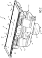
- a perspective view of a blade set 26 for a processing head or cutting head 24 of a hair cutting appliance 10 is shown.
- a cutting direction and/or a direction of a relative movement of blades of the blade set 26 is indicated by an arrow 28.
- a top side of the blade set 26 that is facing the user when the appliance 10 is operated is indicated by 30.
- the blade set 26 is provided with a first leading edge 32 and a second leading edge 34.
- a stationary blade 42 of the blade set 26 is shown.
- a movable blade (cutter blade) is covered by the stationary blade 42 in Fig. 2 .
- Stationary blade teeth are indicated by 44.
- the movable blade of the blade set 26 that is not visible in Fig. 2 is operated and actuated via a driving engagement element 48 that may also be referred to as driving bridge.
- a driving or engagement slot is formed that is engaged by a driving pin 50 of a driving shaft 52.
- the driving shaft 52 is rotated about a driving axis 54, refer to a curved arrow 56.
- the driving pin 50 is off-centered with respect to the driving axis 54. Consequently, as the driving pin 50 is revolving, a reciprocating movement of the movable blade with respect to the stationary blade 42 is effected.
- a pivot mechanism 58 which may be referred to as a contour following feature.
- the mechanism 58 enables a certain pivot movement of the blade set 26 about the Y-axis.
- exemplary insights and aspects of the present disclosure will be described and discussed in more detail.
- manufacturing aspects are discussed that contribute to the production of accurately and reliably operating blade sets that maybe thus implemented in the appliance 10 as illustrated in Fig. 1 , and/or the processing head 24 as illustrated in Fig. 2 .
- Figs. 3 to 14 illustrate schematic, simplified embodiments.
- the support insert may be provided with a slot for a driving element that extends therethrough and that engages the movable blade to transmit a driving movement to the movable blade.
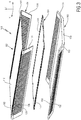
- a blade set 100 is shown that comprises a stationary blade 102 and a movable blade 104.
- the blade set 100 is arranged to replace and/or augment the design of the blade set 26 illustrated in Fig. 2 .
- the blade set 100 is shown in Fig. 3 and Fig. 4 in exploded states.
- a perspective top view is provided, refer to the view orientation of Fig. 2 .
- a perspective bottom view is shown.
- This stationary blade 102 of the blade set 100 is a composed/assembled component.
- This stationary blade 102 comprises a metal component 106 and a support insert 108.
- the metal component 106 and the support insert 108 may be attached to one another to form the stationary blade 102, and to define a guide slot 110 therein that accommodates the movable blade 104, refer to Fig. 6 and to Fig. 14 .
- the metal component 106 is shown in an intermediate assembly state.
- the metal component 106 may be obtained from a sheet metal blank.
- the metal component 106 comprises a top wall 112 that is arranged as a skin-facing wall when the hair cutting appliance 10 that is equipped with the blade set 100 is operated to cut hair.
- a first leg 114 and a second leg 116 are provided that are originally flat portions that are bended/folded to be arranged at a defined angle with respect to the top wall 112.
- the support insert 108 comprises a central portion 120 that is opposite to the top wall 112, and side arms 122, 124 that are contacted by the first leg 114 and the second leg 116 in the mounted state.
- the support insert 108 is an injection-molded plastic part. Therefore, mounting features and further elements may be integrally formed with the support insert 108 (not explicitly shown herein).
- tooth portions 128 and the tooth stems 132 form stationary blade teeth 136.
- the blade set 100 comprises a first leading edge 138 and a second leading edge 140 each of which is provided with a respective series of teeth 136.
- movable blade teeth 144 are formed.
- the movable blade teeth 144 cooperate with the stationary blade teeth 136 to cut hair when the movable blade 104 is operated to be moved with respect to the stationary blade 102.
- the blade set 100 that is provided with the stationary blade 102 may be operated for trimming purposes. However, as the metal component 106 may be considerably thin, at least in some embodiments, the blade set 100 is also operable for shaving operations where a very close skin contact is preferred to achieve a smooth and freshly shaved appearance.
- the support insert 108 is provided to strengthen the stationary blade 102.
- the metal component 106 would be too flexible to efficiently cooperate with the movable blade 104.
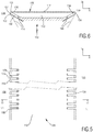
- Fig. 6 illustrates the guide slot 110 that is defined by the metal component 106 and the support insert 108.
- the first leg 114 and the second leg 116 are bent in such a way that the support insert 108 is caught or clamped between the first leg 114 and the second leg 116.
- the first leg 114 and the second leg 116 are folded back to form a clamping holder for the support insert 108.
- the support insert 108 may be regarded as a basically rigid component so that the support insert 108 does not collapse due to the bias applied by the metal component 106.
- the first leg 114 and the second leg 116 are bent about bending shoulders 150 that are formed at the tips of the tooth stems 132. Consequently, tips of the tooth portions 128 of the movable blade 104 that are formed at the transition between the top wall 112 and the two legs 114 and 116, respectively, contact the shoulders 150.
- the bending edge 152 is formed.
- the bending edge 154 is formed.
- Fig. 6 further illustrates by means of a dashed representation intermediate positions of the legs 114, 116 after the first bending procedure, refer also to Fig. 11 . So is it clear that basically opposite deformation procedures are involved to achieve the final assembly state of the legs 114, 116.
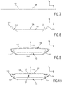
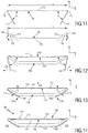
- Figs. 7 to 14 each showing a lateral view of components to be used in the manufacture of blade sets for hair cutting appliances.
- Fig. 7 shows a sheet metal blank 158 having a basically planar shape. From the sheet metal blank 158, metal components 106 may be obtained. In the flat and even state as shown in Fig. 7 , the slots 126 may be processed in the sheet metal blank 158 to define the series of stationary blade teeth 136 that results from the manufacturing procedure.
- Fig. 8 shows a lateral view of the support insert 108 that is to be assembled with the originally flat sheet metal blank 158.
- FIG. 9 an incorrect and defective manufacturing approach is illustrated.
- the support insert 108 is used as the primary bending gage for the folding procedure applied to the sheet metal blank 158 as shown in Fig. 7 without any intermediate bending procedure, quite likely a result as shown in Figs. 9 and 10 will be achieved.
- Fig. 9 an incorrectly manufactured metal component 162 is shown that forms an incorrectly produced stationary blade 164.
- the main reason for the convexly shaped/domed appearance of the metal component 162 is that the sheet metal blank 158 has been bent about the shoulders 150 of the side arms 122, 124 of the support insert 108 without any further preparation and/or intermediate bending procedure.
- the sheet metal material the metal component 162 is formed from is considerably resilient.
- the bending procedure has a negative impact also on the shape and evenness of the top wall 112.
- the bending force applied to the first leg 114 and the second leg 116 induces a reaction that induces an outward doming of the top wall 112.
- An arrow 170 illustrates the doming effect.
- the movable blade 104 is basically rigid and designed to be substantially planar. Hence, a huge gap 168 is formed in a central region of the blade set 166. In the cutting zone, where the stationary blade teeth 136 and the movable blade teeth 144 cooperate, at least a slight gap or offset is present between the metal component 162 and the movable blade 104. To achieve a great cutting performance, however, a close and basically parallel contact between the cutting edges of the stationary blade teeth 136 and the movable blade teeth 144 is preferred.
- FIG. 11 to 14 an alternative manufacturing approach within the context of the present disclosure will be described that may result in a better cutting performance due to an improved dimensional stability of the metal component 106 of the stationary blade 102.
- the approach as discussed hereinafter may also use the sheet metal blank 158 shown in Fig. 7 and the support insert 108 shown in Fig. 8 .
- Fig. 11 an intermediate manufacturing state involving a still detached state of the metal component 106 and the support insert 108 is illustrated.
- a first bending procedure is applied to the metal component 106 before fitting it onto the support insert 108.
- the first leg 114 and the second leg 116 are arranged at an angle ⁇ (alpha) with respect to the top wall 112.
- the angle ⁇ is an inner angle that is defined in a region where the top wall 112 and the two legs 114, 116 face one another.
- the bending angle is a complementary angle (180°- ⁇ ).
- the initial bending procedure defines a certain dimension between the bending edges 152, 154.
- the resulting mounting space is indicated by l b .
- Fig. 11 there is further shown a lateral view of the support insert 108.
- the side arms 122, 124 of the support insert 108 are arranged at an angle ⁇ (beta) with respect to the main extension (longitudinal extension) of the central portion 120.
- the angle ⁇ is smaller than the bending angle of the metal component 106.
- the opposite shoulders 150 of the side arms 122, 124 (or the tooth stems 132) define a longitudinal extension l s .
- the mounting space l b is at least slightly smaller than the longitudinal extension l s (l b ⁇ l s ).
- the metal component 106 and the support insert 108 may only be assembled to one another when a certain clamping force due to the interference between the dimensions l b , l l is borne by the metal component 106.
- the resulting intermediate assembly state is illustrated in Fig. 12 .
- the metal component 106 and the support insert 108 are already force-fitted to one another, due to the dimensional interference.
- a result of the interference between the mounting space l b of the metal component 106 and the longitudinal extension l s of the support insert 108 is that the first leg 114 and the second leg 116 are bent contrary to their initial intermediate bending.
- a resulting angle is indicated in Fig. 12 by ⁇ (gamma).
- a certain deformation (folding out) indicated by the arrows 178 in Fig. 12 happens to the first leg 114 and the second leg 116.
- the metal component 106 is made from relatively elastic and resilient material, the resulting deformation also continues at the top wall 112.
- the top wall 112 is inwardly domed, due to the interference fit of the metal component 106 and the support insert 108.
- a further bending procedure is necessary to connect the first leg 114 and the second leg 116 with their counterpart side arms 122, 124, refer to Fig. 13 .
- a certain fixation force 186 is applied to the first leg 114 and the second leg 116. Due to the elasticity of the metal material, at least in some embodiments, connector portions 188, 190 of the legs 114, 116 are fixedly attached to the support insert 108. This may involve a welding procedure, a bonding procedure, a gluing procedure, etc. In any case, it is necessary to permanently apply the fixation force 186 to avoid a rebound of the first leg 114 and the second leg 116, i.e. a disengagement from opposite bottom sides of the side arms 122, 124.
- the connector portions 188, 190 may be arranged as outermost (inward) points of the first leg 114 and the second leg 116. Hence, a considerably large lever arm is present so that the required fixation force 186 is not too large.
- the fixation force 194, 196 induces a reaction/continuation along the extension of the metal component 106.
- an outward doming effect is present at the top wall 112, refer to the arrow 198.
- the doming effect already discussed in accordance with Fig. 9 and Fig. 10 is still present, with the difference that an opposite deformation of the top wall 112 has been induced before.
- the inward doming 180 shown in Fig. 12 and the outward doming 198 shown in Fig. 13 are similar or equal in terms of the induced deformation.
- a basically planar surface 202 that is sufficiently even may be provided at the top wall 112.
- top wall 112 As shown in Fig. 14 , a tight contact between the top wall 112 and the movable blade 104 is possible when the top wall 112 is basically planar and not considerably deformed during the manufacturing and assembling procedure.
- FIG. 15 schematically illustrating an exemplary embodiment of a method of manufacturing a stationary blade for a blade set of a hair cutting appliance.
- a sheet metal blank is provided based on which a metal component is formed.
- the step S10 may involve, for instance, stamping, cutting, etching, and similar manufacturing processes.
- step S12 at least one pattern of slots is formed in the sheet metal blank.
- the pattern of slots defines a series of teeth.
- the slots may be formed by cutting, particularly laser cutting, etching (electro-chemical processing), cutting, stamping, etc.
- a first bending procedure is applied to the initially flat sheet metal blank.
- a top wall and two opposite legs are formed.
- the first bending procedure involves a bending of the slots so that bending edges are defined that form tooth portions in a downstream manufacturing step.
- the metal component obtained through the steps S10 to S14 is clamp-shaped and arranged to be coupled with a support insert.
- step S16 such a support insert is provided.
- the step S16 may involve injection-molding the support insert.
- the support insert may comprise central portions and two opposite side arms extending therefrom that are inclined with respect to the central portion. At the side arms, tooth stems may be formed that cooperate with the tooth portions of the metal component to form stationary blade teeth in the finally assembled state.
- the metal component and the support insert are assembled. This may involve an insertion of the support insert in a receiving space defined between the first leg and the second leg of the metal component.
- the support insert has an extension that is at least slightly larger than the receiving space provided between the first leg and the second leg of the metal component.
- a pretensioning and a deformation of the metal component is present that is opposite to the initial bending procedure applied in the step S14.
- This deformation may be regarded as a preparation for a further deformation induced at the top wall due to the final assembly step S20.
- the two legs of the metal component are bent further so that connector portions thereof contact the side arms of the support insert.
- the step S20 may involve a fixation of the connector portions at the side arms.
- a resulting deformation is opposite to the deformation of the top wall induced in the step S18.
- a basically flat and even top wall may be achieved which qualifies the stationary blade for an improved cutting performance.
Landscapes
- Engineering & Computer Science (AREA)
- Life Sciences & Earth Sciences (AREA)
- Forests & Forestry (AREA)
- Mechanical Engineering (AREA)
- Manufacturing & Machinery (AREA)
- Dry Shavers And Clippers (AREA)
Priority Applications (7)
| Application Number | Priority Date | Filing Date | Title |
|---|---|---|---|
| EP17194280.8A EP3461602A1 (fr) | 2017-10-02 | 2017-10-02 | Pale fixe et procédé de fabrication |
| US16/652,694 US11351684B2 (en) | 2017-10-02 | 2018-09-24 | Stationary blade and manufacturing method |
| PCT/EP2018/075731 WO2019068492A1 (fr) | 2017-10-02 | 2018-09-24 | Lame fixe, et procédé de fabrication |
| EP18770039.8A EP3691842B1 (fr) | 2017-10-02 | 2018-09-24 | Lame fixe et procédé de fabrication |
| CN201811158632.5A CN109591056B (zh) | 2017-10-02 | 2018-09-30 | 固定刀片以及制造方法 |
| CN201821612826.3U CN209755277U (zh) | 2017-10-02 | 2018-09-30 | 固定刀片和刀片组 |
| US17/831,682 US11772290B2 (en) | 2017-10-02 | 2022-06-03 | Stationary blade and manufacturing method |
Applications Claiming Priority (1)
| Application Number | Priority Date | Filing Date | Title |
|---|---|---|---|
| EP17194280.8A EP3461602A1 (fr) | 2017-10-02 | 2017-10-02 | Pale fixe et procédé de fabrication |
Publications (1)
| Publication Number | Publication Date |
|---|---|
| EP3461602A1 true EP3461602A1 (fr) | 2019-04-03 |
Family
ID=60009493
Family Applications (2)
| Application Number | Title | Priority Date | Filing Date |
|---|---|---|---|
| EP17194280.8A Withdrawn EP3461602A1 (fr) | 2017-10-02 | 2017-10-02 | Pale fixe et procédé de fabrication |
| EP18770039.8A Active EP3691842B1 (fr) | 2017-10-02 | 2018-09-24 | Lame fixe et procédé de fabrication |
Family Applications After (1)
| Application Number | Title | Priority Date | Filing Date |
|---|---|---|---|
| EP18770039.8A Active EP3691842B1 (fr) | 2017-10-02 | 2018-09-24 | Lame fixe et procédé de fabrication |
Country Status (4)
| Country | Link |
|---|---|
| US (2) | US11351684B2 (fr) |
| EP (2) | EP3461602A1 (fr) |
| CN (2) | CN209755277U (fr) |
| WO (1) | WO2019068492A1 (fr) |
Cited By (14)
| Publication number | Priority date | Publication date | Assignee | Title |
|---|---|---|---|---|
| CN110091364A (zh) * | 2019-04-22 | 2019-08-06 | 浙江朗威电器科技有限公司 | 一种毛发切割器具、切割单元、静刀结构及静刀结构的加工工艺 |
| USD914977S1 (en) | 2019-07-19 | 2021-03-30 | Church & Dwight Co., Inc. | Handle for hair removal apparatus |
| USD914978S1 (en) | 2019-10-18 | 2021-03-30 | Church & Dwight Co., Inc. | Hair removal apparatus |
| USD925830S1 (en) | 2019-07-19 | 2021-07-20 | Church & Dwight Co., Inc. | Head assembly for hair removal apparatus |
| EP3854539A1 (fr) * | 2020-01-23 | 2021-07-28 | Braun GmbH | Tondeuse électrique pour barbe |
| EP3907045A1 (fr) * | 2020-05-08 | 2021-11-10 | Braun GmbH | Tondeuse électrique pour barbe |
| EP3907048A1 (fr) * | 2020-05-08 | 2021-11-10 | Braun GmbH | Tondeuse électrique pour barbe |
| USD936900S1 (en) | 2019-10-18 | 2021-11-23 | Church & Dwight Co., Inc. | Hair removal apparatus |
| EP3928932A1 (fr) * | 2020-06-23 | 2021-12-29 | Koninklijke Philips N.V. | Procédés de fabrication d'une fixation de tondeuse à cheveux |
| USD940958S1 (en) | 2019-11-18 | 2022-01-11 | Church & Dwight Co., Inc. | Articulating blade assembly for hair removal device |
| USD942687S1 (en) | 2019-11-18 | 2022-02-01 | Church & Dwight Co., Inc. | Articulating blade assembly for hair removal device |
| USD952946S1 (en) | 2017-09-01 | 2022-05-24 | Church & Dwight Co., Inc. | Hair removal device |
| GB2606932A (en) * | 2020-01-23 | 2022-11-23 | Braun Gmbh | Electric beard trimmer |
| US11642802B2 (en) | 2020-05-08 | 2023-05-09 | Braun Gmbh | Electric beard trimmer |
Families Citing this family (7)
| Publication number | Priority date | Publication date | Assignee | Title |
|---|---|---|---|---|
| FI128465B (en) * | 2017-09-05 | 2020-05-29 | Cross Wrap Oy | A gripping device for gripping an object binding material |
| EP3461602A1 (fr) | 2017-10-02 | 2019-04-03 | Koninklijke Philips N.V. | Pale fixe et procédé de fabrication |
| CN109866258B (zh) * | 2019-04-12 | 2021-04-09 | 浙江朗威电器科技有限公司 | 一种刀头结构 |
| CN110154094A (zh) * | 2019-07-02 | 2019-08-23 | 元海医疗科技有限公司 | 剃毛刀的刀头及其刀片组件 |
| EP3854541A1 (fr) | 2020-01-23 | 2021-07-28 | Braun GmbH | Tondeuse électrique pour barbe |
| EP3854542B1 (fr) | 2020-01-23 | 2023-12-13 | Braun GmbH | Tondeuse à barbe électrique |
| EP3854540A1 (fr) | 2020-01-23 | 2021-07-28 | Braun GmbH | Tondeuse à barbe électrique |
Citations (6)
| Publication number | Priority date | Publication date | Assignee | Title |
|---|---|---|---|---|
| US2249825A (en) * | 1935-03-07 | 1941-07-22 | Gillette Safety Razor Co | Hair clipper |
| US2256029A (en) * | 1938-02-21 | 1941-09-16 | Knapp Monarch Co | Dry shaver cutter head |
| WO2013150412A1 (fr) | 2012-04-03 | 2013-10-10 | Koninklijke Philips N.V. | Ensemble de lame pour appareil de coupe de cheveux et son procédé de fabrication |
| WO2016001019A1 (fr) | 2014-07-04 | 2016-01-07 | Koninklijke Philips N.V. | Ensemble lame, appareil de coupe de cheveux, et procédé de fabrication associé |
| WO2016042158A1 (fr) | 2014-09-18 | 2016-03-24 | Koninklijke Philips N.V. | Ensemble de lames, appareil de coupe de poils, et procédé de fabrication associé |
| CN106346519A (zh) | 2016-10-12 | 2017-01-25 | 吴让攀 | 一种往复式电动剃毛刀头 |
Family Cites Families (15)
| Publication number | Priority date | Publication date | Assignee | Title |
|---|---|---|---|---|
| BE416609A (fr) | 1936-02-15 | |||
| US2151965A (en) * | 1937-04-05 | 1939-03-28 | Clipshave Inc | Hair clipper |
| US2184757A (en) | 1937-10-30 | 1939-12-26 | Samotey John | Shaving device |
| US2251577A (en) | 1938-07-22 | 1941-08-05 | Remington Rand Inc | Electric razor |
| US2266885A (en) | 1939-09-12 | 1941-12-23 | Wendell L Martin | Shaving implement |
| US2290326A (en) | 1939-11-21 | 1942-07-21 | Gillette Safety Razor Co | Dry shaving appliance |
| BE520216A (fr) | 1951-04-26 | |||
| US2948063A (en) * | 1957-05-20 | 1960-08-09 | Sunbeam Corp | Head for electrically operated hair clipping and shaving device |
| DE3229055C2 (de) | 1982-08-04 | 1986-02-13 | Kurt 7230 Schramberg Bäuerle | Halterung einer Scherfolie bei einem Elektrorasiergerät |
| JPS6415086A (en) * | 1987-07-09 | 1989-01-19 | Yoshio Kihara | Card shaver |
| CN100371127C (zh) * | 2004-12-23 | 2008-02-27 | 上海鼎铃电器有限公司 | 一种往复式剃须刀管子动刀头的加工方法 |
| CN103056893A (zh) * | 2013-01-21 | 2013-04-24 | 厦门莱瑞电器有限公司 | 往复式电动剃须刀的外刀改良结构及其加工方法 |
| EP3409432A1 (fr) * | 2017-05-30 | 2018-12-05 | Koninklijke Philips N.V. | Lame fixe, ensemble de lame et procédé de fabrication |
| EP3461602A1 (fr) * | 2017-10-02 | 2019-04-03 | Koninklijke Philips N.V. | Pale fixe et procédé de fabrication |
| EP3466619A1 (fr) * | 2017-10-05 | 2019-04-10 | Koninklijke Philips N.V. | Ensemble de pales et procédé de fabrication |
-
2017
- 2017-10-02 EP EP17194280.8A patent/EP3461602A1/fr not_active Withdrawn
-
2018
- 2018-09-24 EP EP18770039.8A patent/EP3691842B1/fr active Active
- 2018-09-24 US US16/652,694 patent/US11351684B2/en active Active
- 2018-09-24 WO PCT/EP2018/075731 patent/WO2019068492A1/fr unknown
- 2018-09-30 CN CN201821612826.3U patent/CN209755277U/zh not_active Withdrawn - After Issue
- 2018-09-30 CN CN201811158632.5A patent/CN109591056B/zh active Active
-
2022
- 2022-06-03 US US17/831,682 patent/US11772290B2/en active Active
Patent Citations (6)
| Publication number | Priority date | Publication date | Assignee | Title |
|---|---|---|---|---|
| US2249825A (en) * | 1935-03-07 | 1941-07-22 | Gillette Safety Razor Co | Hair clipper |
| US2256029A (en) * | 1938-02-21 | 1941-09-16 | Knapp Monarch Co | Dry shaver cutter head |
| WO2013150412A1 (fr) | 2012-04-03 | 2013-10-10 | Koninklijke Philips N.V. | Ensemble de lame pour appareil de coupe de cheveux et son procédé de fabrication |
| WO2016001019A1 (fr) | 2014-07-04 | 2016-01-07 | Koninklijke Philips N.V. | Ensemble lame, appareil de coupe de cheveux, et procédé de fabrication associé |
| WO2016042158A1 (fr) | 2014-09-18 | 2016-03-24 | Koninklijke Philips N.V. | Ensemble de lames, appareil de coupe de poils, et procédé de fabrication associé |
| CN106346519A (zh) | 2016-10-12 | 2017-01-25 | 吴让攀 | 一种往复式电动剃毛刀头 |
Cited By (27)
| Publication number | Priority date | Publication date | Assignee | Title |
|---|---|---|---|---|
| USD952946S1 (en) | 2017-09-01 | 2022-05-24 | Church & Dwight Co., Inc. | Hair removal device |
| WO2020215345A1 (fr) * | 2019-04-22 | 2020-10-29 | 浙江朗威电器科技有限公司 | Instrument de coupe de cheveux, unité de coupe, structure de dispositif de coupe fixe, et procédé d'usinage de structure de dispositif de coupe fixe |
| CN110091364A (zh) * | 2019-04-22 | 2019-08-06 | 浙江朗威电器科技有限公司 | 一种毛发切割器具、切割单元、静刀结构及静刀结构的加工工艺 |
| USD914977S1 (en) | 2019-07-19 | 2021-03-30 | Church & Dwight Co., Inc. | Handle for hair removal apparatus |
| USD925830S1 (en) | 2019-07-19 | 2021-07-20 | Church & Dwight Co., Inc. | Head assembly for hair removal apparatus |
| USD936900S1 (en) | 2019-10-18 | 2021-11-23 | Church & Dwight Co., Inc. | Hair removal apparatus |
| USD914978S1 (en) | 2019-10-18 | 2021-03-30 | Church & Dwight Co., Inc. | Hair removal apparatus |
| USD936899S1 (en) | 2019-10-18 | 2021-11-23 | Church & Dwight Co., Inc. | Hair removal apparatus |
| USD942687S1 (en) | 2019-11-18 | 2022-02-01 | Church & Dwight Co., Inc. | Articulating blade assembly for hair removal device |
| USD940958S1 (en) | 2019-11-18 | 2022-01-11 | Church & Dwight Co., Inc. | Articulating blade assembly for hair removal device |
| EP3854538A1 (fr) * | 2020-01-23 | 2021-07-28 | Braun GmbH | Tondeuse à barbe électrique |
| WO2021149028A1 (fr) * | 2020-01-23 | 2021-07-29 | Braun Gmbh | Tondeuse à barbe électrique |
| CN115003469B (zh) * | 2020-01-23 | 2023-12-05 | 博朗有限公司 | 切割器系统、电动剃刀或修剪器及制造切割器系统的方法 |
| GB2606932A (en) * | 2020-01-23 | 2022-11-23 | Braun Gmbh | Electric beard trimmer |
| CN115003469A (zh) * | 2020-01-23 | 2022-09-02 | 博朗有限公司 | 电动胡须修剪器 |
| EP3854539A1 (fr) * | 2020-01-23 | 2021-07-28 | Braun GmbH | Tondeuse électrique pour barbe |
| EP3907044A1 (fr) * | 2020-05-08 | 2021-11-10 | Braun GmbH | Tondeuse électrique pour barbe |
| EP3907045A1 (fr) * | 2020-05-08 | 2021-11-10 | Braun GmbH | Tondeuse électrique pour barbe |
| EP3907048A1 (fr) * | 2020-05-08 | 2021-11-10 | Braun GmbH | Tondeuse électrique pour barbe |
| EP3907046A1 (fr) * | 2020-05-08 | 2021-11-10 | Braun GmbH | Tondeuse électrique pour barbe |
| WO2021224851A1 (fr) * | 2020-05-08 | 2021-11-11 | Braun Gmbh | Tondeuse électrique à barbe |
| US11642802B2 (en) | 2020-05-08 | 2023-05-09 | Braun Gmbh | Electric beard trimmer |
| WO2021224848A1 (fr) * | 2020-05-08 | 2021-11-11 | Braun Gmbh | Tondeuse électrique à barbe |
| US11865733B2 (en) | 2020-05-08 | 2024-01-09 | Braun Gmbh | Electric beard trimmer |
| WO2021259833A1 (fr) * | 2020-06-23 | 2021-12-30 | Koninklijke Philips N.V. | Procédés de fabrication d'un accessoire de tondeuse à cheveux |
| EP3928932A1 (fr) * | 2020-06-23 | 2021-12-29 | Koninklijke Philips N.V. | Procédés de fabrication d'une fixation de tondeuse à cheveux |
| JP2023519025A (ja) * | 2020-06-23 | 2023-05-09 | コーニンクレッカ フィリップス エヌ ヴェ | ヘアトリマーアタッチメントの製造方法 |
Also Published As
| Publication number | Publication date |
|---|---|
| WO2019068492A1 (fr) | 2019-04-11 |
| EP3691842B1 (fr) | 2021-05-05 |
| US11772290B2 (en) | 2023-10-03 |
| EP3691842A1 (fr) | 2020-08-12 |
| US11351684B2 (en) | 2022-06-07 |
| US20200316793A1 (en) | 2020-10-08 |
| US20220288799A1 (en) | 2022-09-15 |
| CN209755277U (zh) | 2019-12-10 |
| CN109591056A (zh) | 2019-04-09 |
| CN109591056B (zh) | 2022-02-25 |
Similar Documents
| Publication | Publication Date | Title |
|---|---|---|
| US11772290B2 (en) | Stationary blade and manufacturing method | |
| EP3691843B1 (fr) | Ensemble de pales et procédé de fabrication | |
| EP3630426B1 (fr) | Lame fixe, ensemble de lame et procédé de fabrication | |
| US11370134B2 (en) | Stationary blade, blade set, and manufacturing method | |
| US20200164534A1 (en) | Blade set, hair cutting appliance, and related manufacturing method | |
| JP6118475B1 (ja) | 刃のセット、ヘアカッティング機器、及び、関連する製造方法 |
Legal Events
| Date | Code | Title | Description |
|---|---|---|---|
| PUAI | Public reference made under article 153(3) epc to a published international application that has entered the european phase |
Free format text: ORIGINAL CODE: 0009012 |
|
| AK | Designated contracting states |
Kind code of ref document: A1 Designated state(s): AL AT BE BG CH CY CZ DE DK EE ES FI FR GB GR HR HU IE IS IT LI LT LU LV MC MK MT NL NO PL PT RO RS SE SI SK SM TR |
|
| AX | Request for extension of the european patent |
Extension state: BA ME |
|
| STAA | Information on the status of an ep patent application or granted ep patent |
Free format text: STATUS: THE APPLICATION IS DEEMED TO BE WITHDRAWN |
|
| 18D | Application deemed to be withdrawn |
Effective date: 20191005 |