EP3461519A1 - Medizinische injektionsvorrichtung - Google Patents
Medizinische injektionsvorrichtung Download PDFInfo
- Publication number
- EP3461519A1 EP3461519A1 EP18191673.5A EP18191673A EP3461519A1 EP 3461519 A1 EP3461519 A1 EP 3461519A1 EP 18191673 A EP18191673 A EP 18191673A EP 3461519 A1 EP3461519 A1 EP 3461519A1
- Authority
- EP
- European Patent Office
- Prior art keywords
- hollow cylinder
- injection device
- distal end
- passage
- adapter body
- Prior art date
- Legal status (The legal status is an assumption and is not a legal conclusion. Google has not performed a legal analysis and makes no representation as to the accuracy of the status listed.)
- Granted
Links
Images


Classifications
-
- A—HUMAN NECESSITIES
- A61—MEDICAL OR VETERINARY SCIENCE; HYGIENE
- A61M—DEVICES FOR INTRODUCING MEDIA INTO, OR ONTO, THE BODY; DEVICES FOR TRANSDUCING BODY MEDIA OR FOR TAKING MEDIA FROM THE BODY; DEVICES FOR PRODUCING OR ENDING SLEEP OR STUPOR
- A61M5/00—Devices for bringing media into the body in a subcutaneous, intra-vascular or intramuscular way; Accessories therefor, e.g. filling or cleaning devices, arm-rests
- A61M5/178—Syringes
-
- A—HUMAN NECESSITIES
- A61—MEDICAL OR VETERINARY SCIENCE; HYGIENE
- A61M—DEVICES FOR INTRODUCING MEDIA INTO, OR ONTO, THE BODY; DEVICES FOR TRANSDUCING BODY MEDIA OR FOR TAKING MEDIA FROM THE BODY; DEVICES FOR PRODUCING OR ENDING SLEEP OR STUPOR
- A61M5/00—Devices for bringing media into the body in a subcutaneous, intra-vascular or intramuscular way; Accessories therefor, e.g. filling or cleaning devices, arm-rests
- A61M5/50—Devices for bringing media into the body in a subcutaneous, intra-vascular or intramuscular way; Accessories therefor, e.g. filling or cleaning devices, arm-rests having means for preventing re-use, or for indicating if defective, used, tampered with or unsterile
- A61M5/5013—Means for blocking the piston or the fluid passageway to prevent illegal refilling of a syringe
- A61M5/504—Means for blocking the piston or the fluid passageway to prevent illegal refilling of a syringe for blocking the fluid passageway
-
- A—HUMAN NECESSITIES
- A61—MEDICAL OR VETERINARY SCIENCE; HYGIENE
- A61M—DEVICES FOR INTRODUCING MEDIA INTO, OR ONTO, THE BODY; DEVICES FOR TRANSDUCING BODY MEDIA OR FOR TAKING MEDIA FROM THE BODY; DEVICES FOR PRODUCING OR ENDING SLEEP OR STUPOR
- A61M5/00—Devices for bringing media into the body in a subcutaneous, intra-vascular or intramuscular way; Accessories therefor, e.g. filling or cleaning devices, arm-rests
- A61M5/178—Syringes
- A61M5/31—Details
-
- A—HUMAN NECESSITIES
- A61—MEDICAL OR VETERINARY SCIENCE; HYGIENE
- A61M—DEVICES FOR INTRODUCING MEDIA INTO, OR ONTO, THE BODY; DEVICES FOR TRANSDUCING BODY MEDIA OR FOR TAKING MEDIA FROM THE BODY; DEVICES FOR PRODUCING OR ENDING SLEEP OR STUPOR
- A61M5/00—Devices for bringing media into the body in a subcutaneous, intra-vascular or intramuscular way; Accessories therefor, e.g. filling or cleaning devices, arm-rests
- A61M5/178—Syringes
- A61M5/31—Details
- A61M5/3129—Syringe barrels
- A61M5/3134—Syringe barrels characterised by constructional features of the distal end, i.e. end closest to the tip of the needle cannula
-
- A—HUMAN NECESSITIES
- A61—MEDICAL OR VETERINARY SCIENCE; HYGIENE
- A61M—DEVICES FOR INTRODUCING MEDIA INTO, OR ONTO, THE BODY; DEVICES FOR TRANSDUCING BODY MEDIA OR FOR TAKING MEDIA FROM THE BODY; DEVICES FOR PRODUCING OR ENDING SLEEP OR STUPOR
- A61M5/00—Devices for bringing media into the body in a subcutaneous, intra-vascular or intramuscular way; Accessories therefor, e.g. filling or cleaning devices, arm-rests
- A61M5/178—Syringes
- A61M5/31—Details
- A61M5/315—Pistons; Piston-rods; Guiding, blocking or restricting the movement of the rod or piston; Appliances on the rod for facilitating dosing ; Dosing mechanisms
- A61M5/31511—Piston or piston-rod constructions, e.g. connection of piston with piston-rod
- A61M5/31513—Piston constructions to improve sealing or sliding
-
- A—HUMAN NECESSITIES
- A61—MEDICAL OR VETERINARY SCIENCE; HYGIENE
- A61M—DEVICES FOR INTRODUCING MEDIA INTO, OR ONTO, THE BODY; DEVICES FOR TRANSDUCING BODY MEDIA OR FOR TAKING MEDIA FROM THE BODY; DEVICES FOR PRODUCING OR ENDING SLEEP OR STUPOR
- A61M5/00—Devices for bringing media into the body in a subcutaneous, intra-vascular or intramuscular way; Accessories therefor, e.g. filling or cleaning devices, arm-rests
- A61M5/178—Syringes
- A61M5/31—Details
- A61M5/315—Pistons; Piston-rods; Guiding, blocking or restricting the movement of the rod or piston; Appliances on the rod for facilitating dosing ; Dosing mechanisms
- A61M5/31565—Administration mechanisms, i.e. constructional features, modes of administering a dose
- A61M5/31576—Constructional features or modes of drive mechanisms for piston rods
- A61M5/31578—Constructional features or modes of drive mechanisms for piston rods based on axial translation, i.e. components directly operatively associated and axially moved with plunger rod
- A61M5/3158—Constructional features or modes of drive mechanisms for piston rods based on axial translation, i.e. components directly operatively associated and axially moved with plunger rod performed by axially moving actuator operated by user, e.g. an injection button
-
- A—HUMAN NECESSITIES
- A61—MEDICAL OR VETERINARY SCIENCE; HYGIENE
- A61M—DEVICES FOR INTRODUCING MEDIA INTO, OR ONTO, THE BODY; DEVICES FOR TRANSDUCING BODY MEDIA OR FOR TAKING MEDIA FROM THE BODY; DEVICES FOR PRODUCING OR ENDING SLEEP OR STUPOR
- A61M5/00—Devices for bringing media into the body in a subcutaneous, intra-vascular or intramuscular way; Accessories therefor, e.g. filling or cleaning devices, arm-rests
- A61M5/178—Syringes
- A61M5/31—Details
- A61M5/32—Needles; Details of needles pertaining to their connection with syringe or hub; Accessories for bringing the needle into, or holding the needle on, the body; Devices for protection of needles
- A61M5/34—Constructions for connecting the needle, e.g. to syringe nozzle or needle hub
-
- A—HUMAN NECESSITIES
- A61—MEDICAL OR VETERINARY SCIENCE; HYGIENE
- A61M—DEVICES FOR INTRODUCING MEDIA INTO, OR ONTO, THE BODY; DEVICES FOR TRANSDUCING BODY MEDIA OR FOR TAKING MEDIA FROM THE BODY; DEVICES FOR PRODUCING OR ENDING SLEEP OR STUPOR
- A61M5/00—Devices for bringing media into the body in a subcutaneous, intra-vascular or intramuscular way; Accessories therefor, e.g. filling or cleaning devices, arm-rests
- A61M5/178—Syringes
- A61M5/31—Details
- A61M2005/3128—Incorporating one-way valves, e.g. pressure-relief or non-return valves
-
- A—HUMAN NECESSITIES
- A61—MEDICAL OR VETERINARY SCIENCE; HYGIENE
- A61M—DEVICES FOR INTRODUCING MEDIA INTO, OR ONTO, THE BODY; DEVICES FOR TRANSDUCING BODY MEDIA OR FOR TAKING MEDIA FROM THE BODY; DEVICES FOR PRODUCING OR ENDING SLEEP OR STUPOR
- A61M5/00—Devices for bringing media into the body in a subcutaneous, intra-vascular or intramuscular way; Accessories therefor, e.g. filling or cleaning devices, arm-rests
- A61M5/50—Devices for bringing media into the body in a subcutaneous, intra-vascular or intramuscular way; Accessories therefor, e.g. filling or cleaning devices, arm-rests having means for preventing re-use, or for indicating if defective, used, tampered with or unsterile
- A61M5/5013—Means for blocking the piston or the fluid passageway to prevent illegal refilling of a syringe
- A61M5/504—Means for blocking the piston or the fluid passageway to prevent illegal refilling of a syringe for blocking the fluid passageway
- A61M2005/5046—Means for blocking the piston or the fluid passageway to prevent illegal refilling of a syringe for blocking the fluid passageway automatically, e.g. plug actuated by the piston head, one-way valve
- A61M2005/5053—Valve or plug actuated by fluid flow or fluid pressure allowing initial filling of the syringe
Definitions
- the invention relates to a medical injection device for single use in the administration of a liquid with a hollow cylinder having a cavity for receiving the liquid and a distal end, a arranged in the region of the distal end of the hollow cylinder passage which fluidly connected to the cavity and to a and / or outflow of the liquid from the cavity is provided, a connection portion for releasable fluid-tight connection with a complementary mating connection portion of an injection component, which is arranged such that the passage is fluid-conductively connectable to a lumen of the injection component, and a check valve arrangement, the valve body and a soft-elastic sealing ring having an opening and is arranged and / or designed such that the valve body by means of a distally directed through the passage of the liquid flow from a Freigabepos tion in which the passage is released, at least partially movable in the distal direction through the opening of the sealing ring in a locking position in which the valve body engages behind the opening such that movement of the valve body locked in the release position
- Such an injection device is known from EP 2 153 856 B1 known.
- the known injection device has a hollow cylinder with a cavity for receiving a liquid to be administered.
- the cavity is fluid-conductively connected to a distally located passage.
- the injection device has a connecting section formed in the form of a male luer section on the hollow cylinder. This is releasably fluid-tightly connected to a female luer portion of an injection component called an assembly.
- the injection component has an injection needle at its distal end.
- the passage is fluid-conductively connected to a lumen of the injection component designated as a recess.
- a check valve arrangement is provided.
- This has a soft elastic sealing ring with an opening and a valve body.
- the valve body When administering the liquid, the valve body is distally guided through the opening of the sealing ring by means of the here distally directed flow of liquid from a release position in which the passage is released Lock position moves.
- the valve body engages behind the opening such that a movement of the valve body is locked in the release position and the passage is sealed against a proximally directed flow.
- the check valve arrangement is arranged in the recess of the injection component, which requires a corresponding configuration of the injection component.
- the object of the invention is to provide an injection device of the type mentioned, which has a simplified structure and in particular a use in conjunction with a standardized injection component, in particular a disposable cannula allows.
- an adapter body having a proximal end, which is non-positively and / or positively connected to the distal end of the hollow cylinder, and a distal end, on which the connecting portion is formed, is provided, wherein the check valve arrangement on the proximal end of the adapter body and disposed at the distal end of the hollow cylinder.
- the solution according to the invention makes it possible in particular to dispense with an arrangement of the check valve arrangement on the injection component and, to that extent, on a special embodiment of the injection component in this regard.
- an adapter body which is provided at one end, namely at its distal end, for releasable connection with a preferably standardized injection component and at the other end, namely at its proximal end, connected to the hollow cylinder.
- the adapter body forms so far a kind of transition piece between the hollow cylinder and the injection component.
- the check valve arrangement is arranged according to the invention at the proximal end of the adapter body and the distal end of the hollow cylinder, so that the injection device in conjunction with a conventional - in the sense of not equipped with a check valve assembly - injection component is used.
- the hollow cylinder and the adapter body according to the invention are designed as components manufactured separately from each other, so that in particular the connecting portion of the adapter body can be configured independently of the hollow cylinder and vice versa. In this way, production-side benefits can be achieved.
- the adapter body is preferably connected at its proximal end by means of a positive locking and / or a frictional clamping connection with the hollow cylinder.
- the compound of this type can be designed to be soluble or preferably insoluble.
- the adapter body is made, for example, as a plastic injection molded component.
- the connecting portion may, for example, in the form of a basically known as such, preferably male, Luer-slip or Luer-lock section be formed.
- the connecting portion has a different, preferably standardized, configuration.
- the connecting portion is provided for connection of the adapter body and thus of the injection device with a complementarily configured mating connecting portion of an injection component designed, for example, in the form of a cannula, a hose or the like.
- the check valve arrangement is advantageously self-medium-actuated, so that blocking of the injection device against repeated use can be effected by means of a substantially complete emptying of the liquid through the passage and requires no further action.
- the check valve arrangement is preferably determined in sections on the hollow cylinder and in sections on the adapter body.
- the sealing ring can be fixed at the proximal end of the adapter body and the valve body at the distal end of the hollow cylinder or vice versa.
- proximal and distal refer to a closer or farther position relative to a reference point.
- the hollow cylinder has an integrally formed cylinder base, wherein the valve body is guided axially movably on a guide track extending through the cylinder bottom.
- the guideway may be in the form of a, preferably circular cylindrical, through hole, a recess or the like extending through the cylinder bottom.
- the valve body preferably has a shaft section for the purpose of guiding on the guide track. If the guideway is designed as a circular cylindrical bore, the shank portion may be formed bolt-shaped and slidably fitted in the through hole.
- the cylinder bottom limits the cavity in the distal direction. Preferably, the passage is extended through the cylinder bottom.
- the sealing ring on a clamping portion which is positively fixed between the hollow cylinder, in particular the cylinder bottom, and the adapter body in the axial direction and / or in the radial direction, in particular clamped.
- the clamping section is preferably arranged on a proximal front end of the sealing ring and may be formed, for example, in the form of a radial collar, a collar or the like.
- the clamping portion between the distal end of the hollow cylinder and the proximal end of the adapter body is positively fixed.
- the lumen of the adapter body has a proximally arranged fitting portion into which the sealing ring is fitted.
- the lumen is formed in the form of a through hole extending through the adapter body in the axial direction.
- the fitting section of the lumen can be widened or narrowed in the radial direction with respect to a further course of the lumen. A particularly easy fitment of the sealing ring is achieved when the fitting portion is disposed at a proximal Stirnend Scheme of the lumen.
- the fitting portion on one side in the proximal direction open, undercut radial groove, wherein the sealing ring engages behind the radial groove and is thus fixed in the proximal direction positively on the adapter body. Due to such positive connection of the sealing ring with the fitting portion of this can be set captive on the adapter body in the manufacture of the injection device before connecting the adapter body with the hollow cylinder. This allows easy handling during a final assembly of the injection device, more precisely: when connecting the hollow cylinder to the adapter body.
- the distal end of the hollow cylinder has a latching portion, which is locked in such a manner with a complementary mating latching portion of the adapter body, preferably non-detachably, that the adapter body is fixed in the axial direction of the hollow cylinder.
- the latching portion may have one or more latching lugs, hooks or teeth and the counter-latching portion correspondingly designed detent openings, grooves or the like or vice versa.
- the distal end of the hollow cylinder has a profile section, preferably in the form of a multi-toothing, which is toothed with a complementary mating profile section of the adapter body, that the adapter body is fixed in the circumferential direction of the hollow cylinder. Consequently, an anti-rotation between the hollow cylinder and the adapter body is achieved. In this way, an improved handling of the injection device can be made possible.
- the latching portion and / or the profile section is formed on a circumferential and distal to the cavity, in particular the cylinder bottom, extending collar portion of the hollow cylinder.
- the collar portion is preferably formed integrally with the hollow cylinder.
- the collar portion has a round, preferably circular, cross-section.
- the collar portion may be made as a continuous, contiguous wall portion or alternatively formed by separate, individual wall portions. Easy handling and manufacturability of the injection device is achieved when the collar portion is oriented parallel, preferably coaxially, to a jacket wall of the hollow cylinder.
- the valve body at its distal end on a radially expanded head portion.
- the head section may in particular have a spherical or mushroom-shaped basic shape.
- the dimensions of the head section are advantageously matched to the diameter of the opening of the sealing ring such that the head section is movable by means of a flow of the liquid distally directed through the passage starting from the release position through the opening of the sealing ring and engages behind this in the locking position in a form-fitting manner.
- the head section has a projection which extends in the distal direction and tapers radially.
- the extension may be provided at the end face with a run-up bevel.
- a medical injection device 1 according to Fig. 1 is designed in the form of a disposable syringe and provided for single use in the administration of a medical fluid 2.
- the injection device 1 has a hollow cylinder 3 with a cavity 4 for receiving the liquid 2.
- an actuating punch 5 is provided with a piston 6 arranged on the end face.
- the piston 6 fluid-tightly seals the cavity 4 in the proximal direction P and is slidable in the axial direction relative to an inner wall 7 of the hollow cylinder 3.
- a passage 9 is arranged, the basis of Fig. 1 is indicated only by two dashed lines.
- the passage 9 is fluid-conductively connected to the cavity 4 and provided for the inflow and outflow of the liquid 2 from the cavity 4.
- the passage 9 extends through an integrally formed on the hollow cylinder 3 cylinder bottom 10, which delimits the cavity 4 in the distal direction D.
- the passage 9 is formed of four openings 11.
- the openings 11 are offset in the circumferential direction in each case by 90 ° to each other and arranged concentrically to a central longitudinal axis of the hollow cylinder 3 and each have an annular segment-shaped shape.
- the injection device 1 is connected at its distal end to an injection component in the form of a disposable cannula 12.
- the disposable cannula 12 has a hypodermic injection needle 13 and a needle hub 14.
- the disposable cannula 12 is designed in a fundamentally known manner and in particular has a continuous, based Fig. 1 indicated by dashed lines, lumen 15.
- the lumen 15 of the disposable cannula 12 is fluid-conductively connected to the passage 9 and the cavity 4 in a manner to be described in more detail.
- the Injection device 1 For connection to the disposable cannula 12, the Injection device 1, a connection portion 16 (FIG. Fig. 2 ) on.
- the connecting portion 16 is in the form of a male luer-lock portion and in a generally known, but not shown manner with a formed in the form of a female luer lock portion mating connection portion of the disposable cannula 12 which is disposed on the needle hub 14 , releasably connected fluid-tight.
- an adapter body 17 with a proximal end 18 which is non-positively and / or positively connected to the distal end 8 of the hollow cylinder 3, and a distal end 19, on which the connecting portion 16 is formed, is provided. Furthermore, the adapter body 17 has a lumen 20 in the form of a continuously extending opening. The lumen 20 is fluid-conductively connected at one end to the lumen 15 of the disposable cannula 12 and at the other end in a manner to be described in greater detail to the passage 9 and thus to the cavity 4.
- the adapter body 17 is designed as a component manufactured separately from the hollow cylinder 3, preferably as a plastic injection-molded component, and connected to the hollow cylinder 3 by means of a form-locking detent and a splined connection.
- the distal end 8 of the hollow cylinder 3 has a latching portion 21.
- the latching portion 21 is latched with a complementary counter-latching portion 22 of the adapter body 17, so that the adapter body 17 is fixed in the axial direction of the hollow cylinder 3 ( Fig. 4 ).
- the latching portion 21 is configured in the form of a circumferentially circumferential latching lug.
- the adapter body 17 has a circumferentially circumferential locking groove as a counter-locking portion 22.
- the multi-tooth connection is formed between a profile section 23 formed on the distal end 8 of the hollow cylinder 3 and a complementary mating profile section 24 of the adapter body 17.
- the profile section 23 is formed in the form of a circumferentially continuous multi-toothing with a plurality of axially extending longitudinal grooves.
- the counter-profile section 24 is formed in the form of a blade-side matched to the internal teeth of the profile section 23 external teeth.
- Both the latching section 21 and the profile section 23 are formed on an encircling collar section 25 of the hollow cylinder 3 which extends distally to the cavity 4, or more precisely to the cylinder bottom 10.
- the collar portion 25 extends in the form of a cylinder liner, which is open at its distal end in the axial direction and limited at its proximal end by the cylinder bottom 10.
- the collar portion 25 has a circular cylindrical cross-section and is oriented substantially coaxially to a central longitudinal axis of the hollow cylinder 3.
- the collar portion 25 in comparison to the Hollow cylinder 3 has a smaller diameter and is integrally formed with the cylinder bottom 10 and so far in one piece with the hollow cylinder 3.
- the injection device 1 has a check valve arrangement 26 with a valve body 27 and a soft-elastic sealing ring 28 with an opening 29.
- the check valve arrangement 26 is arranged at the proximal end 18 of the adapter body 17 and at the distal end 8 of the hollow cylinder 3.
- the valve body 27 is guided axially movably on a guide track 30 which extends through the cylinder bottom 10.
- the guideway 30 is in the form of a circular cylindrical bore in the axial direction through the cylinder bottom 10 extends.
- the inner diameter of the guide track 30 is matched to an outer diameter of a shaft portion 31 of the valve body 27 such that it is smoothly and substantially fluid-tightly fitted into the guide track 30.
- the sealing ring 28 has - at least in its particular reference Fig. 2 apparent undeformed configuration - a cap-shaped or bell-shaped basic shape. Both in the axial and in the radial direction of the sealing ring 28 is positively fixed between the hollow cylinder 3, more precisely: the cylinder bottom 10, and the adapter body 17 positively.
- the sealing ring 28 on a clamping portion 32.
- the clamping portion 32 is in particular based on the Fig. 6 to 8 closer and formed at a proximal end of the sealing ring 28 in the form of a radial collar.
- the lumen 20 of the adapter body 17 has a fitting section 33.
- the fitting portion 33 is opposite a further course of the lumen 20 in the radial direction for receiving the sealing ring 28 and also has an open on one side in the proximal direction radial groove 34.
- the clamping portion 32 of the sealing ring 28 widened is fitted into the radial groove 34 of the fitting portion 33.
- valve body 27 at its distal end on a radially opposite the shaft portion 31 expanded head portion 35.
- the head portion 35 is designed mushroom-head-shaped and matched in terms of its outer diameter to the inner diameter of the opening 29 of the sealing ring 28.
- Fig. 6 to 8 will be discussed in more detail below on the function of the check valve assembly 26 and the interaction of the valve body 27 with the sealing ring 28.
- the injection device 1 can be filled or drawn up in a generally known manner by means of a oriented in the proximal direction P movement of the actuating plunger 5 with liquid.
- the piston 6 is moved relative to the inner wall 7 of the hollow cylinder 3 in the proximal direction P and liquid, starting from a liquid reservoir not shown in detail, which is fluidly connected to the lumen 20 of the adapter body 17, through the lumen 20, the opening 29, an intermediate
- the radial section 36 formed in the head portion 35 of the valve body 27 and the sealing ring 28 is sucked into the openings 11 of the passage 9 and further into the cavity 4 of the hollow cylinder 3.
- the valve body 27 remains on a side facing the passage 9 side of the opening 29, which is not essential from the basis Fig. 6 apparent position deviates.
- the piston 6 is moved via the actuating ram 5 in the distal direction D and thus the cavity 4 is pressurized. Due to this pressurization, the liquid 2 passes from the cavity 4 via the openings 11 of the passage 9 and the radial gap 36 in the lumen 20 of the adapter body 17.
- the check valve assembly 26 is designed such that the valve body 27 by means of such a distally directed flow of the liquid 2, starting from the basis Fig.
- valve body 27 due to a proximally directed displacement of the piston 6 under pressure - with respect to the plane of the Fig. 6 to 8 - sucked to the left.
- the passage 9 is sealed as a result of a sealing contact between the sealing ring 28 and the head portion 35.
- further movement of the valve body 27 in the proximal direction P by means of the sealing ring 28 is prevented.
- the sealing ring 28 is soft elastic deformed and curved inward and forms a positive connection with the head portion 35 from. In this way, a repeated use of the injection device 1 is prevented.
- FIGS Fig. 3 . 9 or 10 Further embodiments of injection devices 1a, 1b, 1c according to the invention are described with reference to FIGS Fig. 3 . 9 or 10 can be seen.
- the embodiments according to the Fig. 3 . 9 as well as 10 are essentially the same as previously Fig. 1 . 2 and 4 to 8 described embodiment. To avoid repetition, reference is therefore made to the disclosure of the embodiment of the latter figures.
- Components and sections that are identical to the injection device 1 in the injection devices 1a to 1c are provided with identical reference numerals. Functionally identical components and sections, which are different in their structural design, are denoted by the same reference numerals with the addition of lowercase letters.
- the injection device 1a according to Fig. 3 differs from the injection device 1 ( Fig. 2 ) in that an adapter body 17a is provided which, instead of a luer-lock section, has a connection section 16a designed in the form of a luer-slip section.
- the hollow cylinder 3 and provided for connection to the adapter body 17 a collar portion 25 are unchanged.
- the hollow cylinder 3 can be manufactured independently of the configuration of the connecting portion 16, 16a and vice versa.
- production and assembly-side benefits can be achieved.
- the injection device 1b differs Fig. 9 essentially to the effect that a different configuration of the positive connection between a sealing ring 28b and an adapter body 17b is provided. More specifically, a fitting portion 33b of a lumen 20b is provided with an undercut radial groove 34b. A radial groove 34b is open on one side in the proximal direction P, wherein the groove bottom tapers in the proximal direction P radially.
- a clamping section 32b of the sealing ring 28b is designed to be complementary in accordance with the groove profile of the radial groove 34b and thus engages behind it in a form-fitting manner in the proximal direction. Before a production-side assembly of the adapter body 17b with the collar portion 25 of the hollow cylinder 3, the sealing ring 28b can thus be secured captive on the adapter body 17b. This allows in particular a simplified handling during assembly.
- the injection device 1c after Fig. 10 differs from the injection device 1b after Fig. 9 merely in that the local valve body 27c has a modified head section 35c.
- the head portion 35c has a distally extending and radially tapered extension 37.
Landscapes
- Health & Medical Sciences (AREA)
- Vascular Medicine (AREA)
- Engineering & Computer Science (AREA)
- Anesthesiology (AREA)
- Biomedical Technology (AREA)
- Heart & Thoracic Surgery (AREA)
- Hematology (AREA)
- Life Sciences & Earth Sciences (AREA)
- Animal Behavior & Ethology (AREA)
- General Health & Medical Sciences (AREA)
- Public Health (AREA)
- Veterinary Medicine (AREA)
- Infusion, Injection, And Reservoir Apparatuses (AREA)
Abstract
Description
- Die Erfindung betrifft eine medizinische Injektionsvorrichtung zur Einmalverwendung bei der Verabreichung einer Flüssigkeit mit einem Hohlzylinder, der einen Hohlraum zur Aufnahme der Flüssigkeit sowie ein distales Ende aufweist, einem im Bereich des distalen Endes des Hohlzylinders angeordneten Durchlass, der fluidleitend mit dem Hohlraum verbunden und zum Ein- und/oder Ausströmen der Flüssigkeit aus dem Hohlraum vorgesehen ist, einem Verbindungsabschnitt zur lösbaren fluiddichten Verbindung mit einem komplementären Gegenverbindungsabschnitt einer Injektionskomponente, der derart angeordnet ist, dass der Durchlass fluidleitend mit einem Lumen der Injektionskomponente verbindbar ist, und einer Sperrventilanordnung, die einen Ventilkörper und einen weichelastischen Dichtring mit einer Öffnung aufweist und derart angeordnet und/oder gestaltet ist, dass der Ventilkörper mittels einer distal durch den Durchlass gerichteten Strömung der Flüssigkeit ausgehend von einer Freigabeposition, in welcher der Durchlass freigegeben ist, wenigstens abschnittsweise in distale Richtung durch die Öffnung des Dichtringes in eine Sperrposition beweglich ist, in welcher der Ventilkörper die Öffnung derart hintergreift, dass eine Bewegung des Ventilkörpers in die Freigabeposition gesperrt und der Durchlass gegen eine proximal gerichtete Strömung abgedichtet ist.
- Eine derartige Injektionsvorrichtung ist aus der
EP 2 153 856 B1 bekannt. Die bekannte Injektionsvorrichtung weist einen Hohlzylinder mit einem Hohlraum zur Aufnahme einer zu verabreichenden Flüssigkeit auf. Der Hohlraum ist fluidleitend mit einem distal angeordneten Durchlass verbunden. Weiter weist die Injektionsvorrichtung einen an dem Hohlzylinder ausgebildeten Verbindungsabschnitt in Form eines männlichen Luer-Abschnittes auf. Dieser ist lösbar fluiddicht mit einem weiblichen Luer-Abschnitt einer als Zusammenbau bezeichneten Injektionskomponente verbunden. Die Injektionskomponente weist an ihrem distalen Ende eine Injektionsnadel auf. Der Durchlass ist fluidleitend mit einem als Ausnehmung bezeichneten Lumen der Injektionskomponente verbunden. Mittels Einwirkung eines in dem Hohlzylinder in distale Richtung bewegten Kolbens kann Flüssigkeit ausgehend von dem Hohlraum über den Durchlass durch das Lumen aus der Injektionsnadel gepresst und somit einem Patienten verabreicht werden. Um eine nochmalige Verwendung der Injektionsvorrichtung zu unterbinden und somit der Übertragung von Krankheitserregern vorzubeugen, ist eine Sperrventilanordnung vorgesehen. Diese weist einen weichelastischen Dichtring mit einer Öffnung und einen Ventilkörper auf. Beim Verabreichen der Flüssigkeit wird der Ventilkörper mittels der hierbei distal gerichteten Strömung der Flüssigkeit ausgehend von einer Freigabeposition, in welcher der Durchlass freigegeben ist, in distaler Richtung durch die Öffnung des Dichtringes in eine Sperrposition bewegt. In dieser hintergreift der Ventilkörper die Öffnung derart, dass eine Bewegung des Ventilkörpers in die Freigabeposition gesperrt und der Durchlass gegen eine proximal gerichtete Strömung abgedichtet ist. Auf diese Weise ist die bekannte Injektionsvorrichtung gegen ein nochmaliges Aufziehen des Hohlraumes mit Flüssigkeit gesichert. Bei der bekannten Injektionsvorrichtung ist die Sperrventilanordnung in der Ausnehmung der Injektionskomponente angeordnet, was eine dementsprechende Ausgestaltung der Injektionskomponente erforderlich macht. - Aufgabe der Erfindung ist es, eine Injektionsvorrichtung der eingangs genannten Art zu schaffen, die einen vereinfachten Aufbau aufweist und insbesondere eine Verwendung in Verbindung mit einer standardisierten Injektionskomponente, insbesondere einer Einwegkanüle, ermöglicht.
- Diese Aufgabe wird dadurch gelöst, dass ein Adapterkörper mit einem proximalen Ende, das kraft- und/oder formschlüssig mit dem distalen Ende des Hohlzylinders verbunden ist, und einem distalen Ende, an dem der Verbindungsabschnitt ausgebildet ist, vorgesehen ist, wobei die Sperrventilanordnung an dem proximalen Ende des Adapterkörpers und an dem distalen Ende des Hohlzylinders angeordnet ist. Durch die erfindungsgemäße Lösung kann insbesondere auf eine Anordnung der Sperrventilanordnung an der Injektionskomponente und insoweit auf eine spezielle diesbezügliche Ausgestaltung der Injektionskomponente verzichtet werden. Denn erfindungsgemäß ist ein Adapterkörper vorgesehen, der einends, nämlich an seinem distalen Ende, zur lösbaren Verbindung mit einer, vorzugsweise standardisierten, Injektionskomponente vorgesehen und andernends, nämlich an seinem proximalen Ende, mit dem Hohlzylinder verbunden ist. Der Adapterkörper bildet insoweit eine Art Übergangsstück zwischen dem Hohlzylinder und der Injektionskomponente. Hierbei ist die Sperrventilanordnung erfindungsgemäß am proximalen Ende des Adapterkörpers und dem distalen Ende des Hohlzylinders angeordnet, so dass die Injektionsvorrichtung in Verbindung mit einer üblichen - im Sinne von nicht mit einer Sperrventilanordnung ausgestatteten - Injektionskomponente verwendbar ist. Zudem sind der Hohlzylinder und der Adapterkörper erfindungsgemäß als separat voneinander gefertigte Bauelemente ausgebildet, so dass insbesondere der Verbindungsabschnitt des Adapterkörpers unabhängig von dem Hohlzylinder ausgestaltet sein kann und umgekehrt. Auf diese Weise können fertigungsseitige Vorteile erreicht werden. Der Adapterkörper ist an seinem proximalen Ende vorzugsweise mittels einer formschlüssigen Rast- und/oder einer reibschlüssigen Klemmverbindung mit dem Hohlzylinder verbunden. Die derartige Verbindung kann lös- oder bevorzugt unlösbar gestaltet sein. Der Adapterkörper ist beispielsweise als Kunststoffspritzgussbauteil gefertigt. Der Verbindungsabschnitt kann beispielsweise in Form eines als solchen grundsätzlich bekannten, vorzugsweise männlichen, Luer-Slip- oder Luer-Lock-Abschnittes ausgebildet sein. Alternativ ist es möglich, dass der Verbindungsabschnitt eine andersartige, vorzugsweise standardisierte, Ausgestaltung aufweist. Der Verbindungsabschnitt ist zur Verbindung des Adapterkörpers und damit der Injektionsvorrichtung mit einem komplementär ausgestalteten Gegenverbindungsabschnitts einer beispielsweise in Form einer Kanüle, eines Schlauches oder dergleichen gestalteten Injektionskomponente vorgesehen. Die Sperrventilanordnung ist vorteilhafterweise eigenmediumbetätigt, so dass eine Sperrung der Injektionsvorrichtung gegen eine nochmalige Verwendung mittels einer im Wesentlichen vollständigen Entleerung der Flüssigkeit durch den Durchlass bewirkbar ist und keiner weiteren Handlung bedarf. Die Sperrventilanordnung ist vorzugsweise abschnittsweise an dem Hohlzylinder und abschnittsweise an dem Adapterkörper festgelegt. Beispielsweise kann der Dichtring am proximalen Ende des Adapterkörpers und der Ventilkörper am distalen Ende des Hohlzylinders festgelegt sein oder umgekehrt. Die Begriffe proximal und distal bezeichnen eine in Bezug auf einen Referenzpunkt nähere bzw. weiter entfernte Lage.
- In Ausgestaltung der Erfindung weist der Hohlzylinder einen einstückig angeformten Zylinderboden auf, wobei der Ventilkörper an einer durch den Zylinderboden erstreckten Führungsbahn axial beweglich geführt ist. Die Führungsbahn kann in Form einer, vorzugsweise kreiszylindrischen, Durchgangsbohrung, einer Ausnehmung oder dergleichen durch den Zylinderboden erstreckt sein. Der Ventilkörper weist zum Zwecke der Führung an der Führungsbahn vorzugsweise einen Schaftabschnitt auf. Sofern die Führungsbahn als kreiszylindrische Bohrung gestaltet ist, kann der Schaftabschnitt bolzenförmig gestaltet und gleitbeweglich in die Durchgangsbohrung eingepasst sein. Der Zylinderboden begrenzt den Hohlraum in distaler Richtung. Vorzugsweise ist der Durchlass durch den Zylinderboden erstreckt.
- In weiterer Ausgestaltung der Erfindung weist der Dichtring einen Klemmabschnitt auf, der zwischen dem Hohlzylinder, insbesondere dem Zylinderboden, und dem Adapterkörper in Axialrichtung und/oder in Radialrichtung formschlüssig festgelegt, insbesondere geklemmt, ist. Der Klemmabschnitt ist vorzugsweise an einem proximalen Stirnende des Dichtringes angeordnet und kann beispielsweise in Form eines Radialbundes, eines Kragens oder dergleichen ausgebildet sein. Vorzugsweise ist der Klemmabschnitt zwischen dem distalen Ende des Hohlzylinders und dem proximalen Ende des Adapterkörpers formschlüssig festgelegt. Diese Ausgestaltung der Erfindung erlaubt eine besonders einfache Montage der Injektionsvorrichtung.
- In weiterer Ausgestaltung der Erfindung weist das Lumen des Adapterkörpers einen proximal angeordneten Passabschnitt auf, in den der Dichtring eingepasst ist. Das Lumen ist in Form einer in Axialrichtung durch den Adapterkörper erstreckten Durchgangsöffnung ausgebildet. Der Passabschnitt des Lumens kann gegenüber einem weiteren Verlauf des Lumens in radialer Richtung aufgeweitet oder verengt sein. Eine besonders einfache Einpassbarkeit des Dichtringes wird erreicht, wenn der Passabschnitt an einem proximalen Stirnendbereich des Lumens angeordnet ist.
- In weiterer Ausgestaltung der Erfindung weist der Passabschnitt eine einseitig in proximale Richtung offene, hinterschnittene Radialnut auf, wobei der Dichtring die Radialnut hintergreift und somit in proximaler Richtung formschlüssig an dem Adapterkörper festgelegt ist. Aufgrund der derartigen formschlüssigen Verbindung des Dichtringes mit dem Passabschnitt kann dieser bei der Fertigung der Injektionsvorrichtung vor einem Verbinden des Adapterkörpers mit dem Hohlzylinder verliersicher an dem Adapterkörper festgelegt werden. Dies erlaubt eine einfache Handhabung während einer Endmontage der Injektionsvorrichtung, genauer: bei einem Verbinden des Hohlzylinders mit dem Adapterkörper.
- In weiterer Ausgestaltung der Erfindung weist das distale Ende des Hohlzylinders einen Rastabschnitt auf, der derart mit einem komplementären Gegenrastabschnitt des Adapterkörpers, vorzugsweise unlösbar, verrastet ist, dass der Adapterkörper in Axialrichtung an dem Hohlzylinder festgelegt ist. Der Rastabschnitt kann eine oder mehrere Rastnasen, -haken oder -zähne und der Gegenrastabschnitt dementsprechend komplementär gestaltete Rastöffnungen, -nuten oder dergleichen aufweisen oder umgekehrt. Mittels der derartigen Rastverbindung sind der Hohlzylinder und der Adapterkörper wenigstens in Axialrichtung fest miteinander verbunden, so dass einem unbeabsichtigten Abziehen des Adapterkörpers von dem Hohlzylinder oder umgekehrt entgegengewirkt ist.
- In weiterer Ausgestaltung der Erfindung weist das distale Ende des Hohlzylinders einen Profilabschnitt, vorzugsweise in Form einer Vielverzahnung auf, der derart mit einem komplementären Gegenprofilabschnitt des Adapterkörpers verzahnt ist, dass der Adapterkörper in Umfangsrichtung an dem Hohlzylinder festgelegt ist. Demzufolge ist eine Verdrehsicherung zwischen dem Hohlzylinder und dem Adapterkörper erreicht. Auf diese Weise kann eine verbesserte Handhabung der Injektionsvorrichtung ermöglicht werden.
- In weiterer Ausgestaltung der Erfindung ist der Rastabschnitt und/oder der Profilabschnitt an einem umlaufenden und distal zu dem Hohlraum, insbesondere dem Zylinderboden, erstreckten Kragenabschnitt des Hohlzylinders ausgebildet. Der Kragenabschnitt ist vorzugsweise einstückig mit dem Hohlzylinder ausgebildet. Vorzugsweise weist der Kragenabschnitt einen runden, bevorzugt kreisförmigen, Querschnitt auf. Der Kragenabschnitt kann als ein durchgehender, zusammenhängender Wandungsabschnitt gefertigt sein oder alternativ durch voneinander getrennte, einzelne Wandabschnitte gebildet sein. Eine einfache Handhabung und Fertigbarkeit der Injektionsvorrichtung wird erreicht, wenn der Kragenabschnitt parallel, vorzugsweise koaxial, zu einer Mantelwandung des Hohlzylinders orientiert ist.
- In weiterer Ausgestaltung der Erfindung weist der Ventilkörper an seinem distalen Ende einen radial aufgeweiteten Kopfabschnitt auf. Der Kopfabschnitt kann insbesondere eine kugel- oder pilzkopfförmige Grundform aufweisen. Die Abmessungen des Kopfabschnittes sind vorteilhafterweise derart auf den Durchmesser der Öffnung des Dichtringes abgestimmt, dass der Kopfabschnitt mittels einer distal durch den Durchlass gerichteten Strömung der Flüssigkeit ausgehend von der Freigabeposition durch die Öffnung des Dichtringes beweglich ist und diese in der Sperrposition formschlüssig hintergreift.
- In weiterer Ausgestaltung der Erfindung weist der Kopfabschnitt einen in distale Richtung erstreckten und radial verjüngten Fortsatz auf. Der Fortsatz kann stirnendseitig mit einer Anlaufschrägung versehen sein. Mittels des Fortsatzes kann insbesondere eine verbesserte Zentrierung des Ventilkörpers in der Öffnung des Dichtringes erreicht werden.
- Weitere Vorteile und Merkmale der Erfindung ergeben sich aus den Ansprüchen sowie aus der nachfolgenden Beschreibung bevorzugter Ausführungsbeispiele der Erfindung, die anhand der Zeichnungen dargestellt sind.
- Fig. 1
- zeigt in schematischer, teilweiser geschnittener Seitenansicht eine Ausführungsform einer erfindungsgemäßen Injektionsvorrichtung, die lösbar mit einer Injektionskomponente in Form einer Einwegkanüle verbunden ist,
- Fig. 2
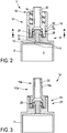
- in schematischer Längsschnittdarstellung die Injektionsvorrichtung nach
Fig. 1 im Bereich einer Sperrventilanordnung, - Fig. 3
- eine weitere Ausführungsform einer erfindungsgemäßen Injektionsvorrichtung in einer Längsschnittdarstellung entsprechend
Fig. 2 , - Fig. 4
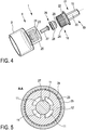
- in einer schematischen, perspektivischen Explosionsdarstellung die Infusionsvorrichtung nach den
Fig. 1 und2 im Bereich der Sperrventilanordnung, - Fig. 5
- in einer schematischen Querschnittsdarstellung entlang einer Schnittlinie A-A gemäß
Fig. 2 die Injektionsvorrichtung nach denFig. 1 ,2 und4 , - Fig. 6 bis 8
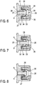
- jeweils in abgeschnittener Längsschnittdarstellung die Sperrventilanordnung der Injektionsvorrichtungen nach den
Fig. 1 bis 5 in unterschiedlichen Positionen bei einer Verlagerung von einer Freigabe- in eine Sperrposition, - Fig. 9
- in einer abgeschnittenen schematischen Längsschnittdarstellung eine weitere Ausführungsform einer erfindungsgemäßen Injektionsvorrichtung und
- Fig. 10
- in einer Darstellung entsprechend
Fig. 9 eine weitere Ausführungsform einer erfindungsgemäßen Injektionsvorrichtung. - Eine medizinische Injektionsvorrichtung 1 nach
Fig. 1 ist in Form einer Einwegspritze gestaltet und zur Einmalverwendung bei der Verabreichung einer medizinischen Flüssigkeit 2 vorgesehen. - Die Injektionsvorrichtung 1 weist einen Hohlzylinder 3 mit einem Hohlraum 4 zur Aufnahme der Flüssigkeit 2 auf. Zur manuellen Betätigung der Injektionsvorrichtung ist ein Betätigungsstempel 5 mit einem stirnendseitig angeordneten Kolben 6 vorgesehen. Der Kolben 6 dichtet den Hohlraum 4 in proximaler Richtung P fluiddicht ab und ist gegenüber einer Innenwandung 7 des Hohlzylinders 3 in Axialrichtung gleitbeweglich. Am distalen Ende 8 des Hohlzylinders 3 ist ein Durchlass 9 angeordnet, der anhand
Fig. 1 lediglich mittels zweier strichlierter Linien angedeutet ist. Der Durchlass 9 ist fluidleitend mit dem Hohlraum 4 verbunden und zum Ein- und Ausströmen der Flüssigkeit 2 aus dem Hohlraum 4 vorgesehen. Wie insbesondere anhandFig. 2 ersichtlich ist, erstreckt sich der Durchlass 9 durch einen einstückig an den Hohlzylinder 3 angeformten Zylinderboden 10, der den Hohlraum 4 in distaler Richtung D begrenzt. Anhand der Querschnittsdarstellung derFig. 5 ist ersichtlich, dass der Durchlass 9 aus vier Öffnungen 11 gebildet ist. Die Öffnungen 11 sind in Umfangsrichtung jeweils um 90° versetzt zueinander und konzentrisch zu einer Mittellängsachse des Hohlzylinders 3 angeordnet und weisen jeweils eine kreisringsegmentförmige Gestalt auf. Die Injektionsvorrichtung 1 ist an ihrem distalen Ende mit einer Injektionskomponente in Form einer Einwegkanüle 12 verbunden. Die Einwegkanüle 12 weist eine hypodermische Injektionsnadel 13 und einen Nadelansatz 14 auf. Die Einwegkanüle 12 ist auf grundsätzlich bekannte Weise gestaltet und weist insbesondere ein durchgängiges, anhandFig. 1 strichliert angedeutetes, Lumen 15 auf. Das Lumen 15 der Einwegkanüle 12 ist auf noch näher zu beschreibende Art und Weise mit dem Durchlass 9 und dem Hohlraum 4 fluidleitend verbunden. Zur Verbindung mit der Einwegkanüle 12 weist die Injektionsvorrichtung 1 einen Verbindungsabschnitt 16 (Fig. 2 ) auf. Der Verbindungsabschnitt 16 ist in Form eines männlichen Luer-Lock-Abschnittes gestaltet und auf grundsätzlich bekannte, jedoch nicht näher dargestellte Art und Weise mit einem in Form eines weiblichen Luer-Lock-Abschnittes gestalteten Gegenverbindungsabschnitt der Einwegkanüle 12, der an dem Nadelansatz 14 angeordnet ist, lösbar fluiddicht verbunden. - Wie insbesondere anhand der
Fig. 2 und4 ersichtlich ist, ist ein Adapterkörper 17 mit einem proximalen Ende 18, das kraft- und/oder formschlüssig mit dem distalen Ende 8 des Hohlzylinders 3 verbunden ist, und einem distalen Ende 19, an dem der Verbindungsabschnitt 16 ausgebildet ist, vorgesehen. Weiter weist der Adapterkörper 17 ein Lumen 20 in Form einer durchgängig erstreckten Öffnung auf. Das Lumen 20 ist einends fluidleitend mit dem Lumen 15 der Einwegkanüle 12 und andernends auf noch näher zu beschreibende Weise fluidleitend mit dem Durchlass 9 und somit dem Hohlraum 4 verbunden. Der Adapterkörper 17 ist als ein separat von dem Hohlzylinder 3 gefertigtes Bauteil ausgebildet, vorzugsweise als Kunststoffspritzgussbauteil, und mittels einer formschlüssigen Rast- sowie einer Vielzahnverbindung mit dem Hohlzylinder 3 verbunden. Hierfür weist das distale Ende 8 des Hohlzylinders 3 einen Rastabschnitt 21 auf. Der Rastabschnitt 21 ist mit einem komplementären Gegenrastabschnitt 22 des Adapterkörpers 17 verrastet, so dass der Adapterkörper 17 in Axialrichtung an dem Hohlzylinder 3 festgelegt ist (Fig. 4 ). Der Rastabschnitt 21 ist in Form einer in Umfangsrichtung umlaufenden Rastnase ausgestaltet. Hierzu komplementär weist der Adapterkörper 17 eine in Umfangsrichtung umlaufende Rastnut als Gegenrastabschnitt 22 auf. Die Vielzahnverbindung ist zwischen einem am distalen Ende 8 des Hohlzylinders 3 ausgebildeten Profilabschnitt 23 und einem komplementären Gegenprofilabschnitt 24 des Adapterkörpers 17 ausgebildet. Auf diese Weise ist der Adapterkörper 17 in Umfangsrichtung an dem Hohlzylinder 3 festgelegt und gegen ein ungewolltes Verdrehen gesichert. Der Profilabschnitt 23 ist in Form einer in Umfangsrichtung durchgängigen Vielverzahnung mit einer Vielzahl von in Axialrichtung erstreckten Längsnuten ausgebildet. Dementsprechend ist der Gegenprofilabschnitt 24 in Form einer abmesserseitig auf die Innenverzahnung des Profilabschnittes 23 abgestimmte Außenverzahnung ausgebildet. - Sowohl der Rastabschnitt 21 als auch der Profilabschnitt 23 sind an einem umlaufenden und distal zu dem Hohlraum 4, genauer: dem Zylinderboden 10, erstreckten Kragenabschnitt 25 des Hohlzylinders 3 ausgebildet. Der Kragenabschnitt 25 erstreckt sich in Form einer Zylinderbuchse, die an ihrem distalen Ende in Axialrichtung offen und an ihrem proximalen Ende durch den Zylinderboden 10 begrenzt ist. Der Kragenabschnitt 25 weist einen kreiszylindrischen Querschnitt auf und ist im Wesentlichen koaxial zu einer Mittellängsachse des Hohlzylinders 3 orientiert. Weiter weist der Kragenabschnitt 25 im Vergleich zu dem Hohlzylinder 3 einen geringeren Durchmesser auf und ist einstückig mit dem Zylinderboden 10 und insoweit einstückig mit dem Hohlzylinder 3 ausgebildet.
- Weiter weist die Injektionsvorrichtung 1 eine Sperrventilanordnung 26 mit einem Ventilkörper 27 und einem weichelastischen Dichtring 28 mit einer Öffnung 29 auf. Die Sperrventilanordnung 26 ist an dem proximalen Ende 18 des Adapterkörpers 17 und an dem distalen Ende 8 des Hohlzylinders 3 angeordnet.
- Der Ventilkörper 27 ist an einer durch den Zylinderboden 10 erstreckten Führungsbahn 30 axialbeweglich geführt. Die Führungsbahn 30 ist in Form einer kreiszylindrischen Bohrung in Axialrichtung durch den Zylinderboden 10 erstreckt. Der Innendurchmesser der Führungsbahn 30 ist derart auf einen Außendurchmesser eines Schaftabschnittes 31 des Ventilkörpers 27 abgestimmt, dass dieser leichtgängig und im Wesentlichen fluiddicht in die Führungsbahn 30 eingepasst ist.
- Der Dichtring 28 weist - jedenfalls in seiner insbesondere anhand
Fig. 2 ersichtlichen undeformierten Konfiguration - eine kappen- oder glockenförmige Grundform auf. Sowohl in Axial- als auch in Radialrichtung ist der Dichtring 28 formschlüssig zwischen dem Hohlzylinder 3, genauer: dem Zylinderboden 10, und dem Adapterkörper 17 formschlüssig festgelegt. Zu diesem Zweck weist der Dichtring 28 einen Klemmabschnitt 32 auf. Der Klemmabschnitt 32 ist insbesondere anhand derFig. 6 bis 8 näher ersichtlich und an einem proximalen Ende des Dichtringes 28 in Form eines Radialbundes ausgebildet. Zur Anordnung des Dichtringes 28 an dem Adapterkörper 17 ist dessen proximales Ende 18 dementsprechend gestaltet. So weist das Lumen 20 des Adapterkörpers 17 einen Passabschnitt 33 auf. Der Passabschnitt 33 ist gegenüber einem weiteren Verlauf des Lumens 20 in radialer Richtung zur Aufnahme des Dichtringes 28 und weist zudem eine einseitig in proximale Richtung offene Radialnut 34 auf. Der Klemmabschnitt 32 des Dichtringes 28 aufgeweitet ist in die Radialnut 34 des Passabschnittes 33 eingepasst. - Wie weiter insbesondere anhand der
Fig. 6 bis 8 ersichtlich ist, weist der Ventilkörper 27 an seinem distalen Ende einen radial gegenüber dem Schaftabschnitt 31 aufgeweiteten Kopfabschnitt 35 auf. Der Kopfabschnitt 35 ist pilzkopfförmig ausgestaltet und hinsichtlich seines Außendurchmessers auf den Innendurchmesser der Öffnung 29 des Dichtringes 28 abgestimmt. Insbesondere anhand derFig. 6 bis 8 wird nachfolgend näher auf die Funktion der Sperrventilanordnung 26 und das Zusammenwirken des Ventilkörpers 27 mit dem Dichtring 28 eingegangen. - Ausgehend von der anhand
Fig. 6 ersichtlichen Konfiguration der Sperrventilanordnung 26, die als Freigabeposition bezeichnet wird, kann die Injektionsvorrichtung 1 auf grundsätzlich bekannte Weise mittels einer in proximaler Richtung P orientierten Bewegung des Betätigungsstempels 5 mit Flüssigkeit befüllt bzw. aufgezogen werden. Hierbei wird der Kolben 6 gegenüber der Innenwandung 7 des Hohlzylinders 3 in proximale Richtung P bewegt und Flüssigkeit ausgehend von einem nicht näher ersichtlichen Flüssigkeitsreservoir, das mit dem Lumen 20 des Adapterkörpers 17 fluidleitend verbunden ist, durch das Lumen 20, die Öffnung 29, einen zwischen dem Kopfabschnitt 35 des Ventilkörpers 27 und dem Dichtring 28 ausgebildeten Radialspalt 36, in die Öffnungen 11 des Durchlasses 9 und weiter in den Hohlraum 4 des Hohlzylinders 3 gesaugt. Hierbei verbleibt der Ventilkörper 27 auf einer dem Durchlass 9 zugewandten Seite der Öffnung 29, die nicht wesentlich von der anhandFig. 6 ersichtlichen Position abweicht. - Zum Entleeren der Injektionsvorrichtung 1 wird der Kolben 6 über den Betätigungsstempel 5 in distale Richtung D bewegt und somit der Hohlraum 4 druckbeaufschlagt. Aufgrund dieser Druckbeaufschlagung gelangt die Flüssigkeit 2 aus dem Hohlraum 4 über die Öffnungen 11 des Durchlasses 9 und den Radialspalt 36 in das Lumen 20 des Adapterkörpers 17. Soweit die Einwegkanüle 12 mit dem Adapterkörper 17 verbunden ist - wie exemplarisch anhand
Fig. 1 dargestellt - gelangt die Flüssigkeit 2 weiter von dem Lumen 20 in das Lumen 15 bis zu einer Austrittsöffnung der Injektionsnadel 13 und kann derart einen Patienten verabreicht werden. Hierbei ist die Sperrventilanordnung 26 derart gestaltet, dass der Ventilkörper 27 mittels einer solchen distal gerichteten Strömung der Flüssigkeit 2 ausgehend von der anhandFig. 6 ersichtlichen Freigabeposition durch die Öffnung 29 des Dichtringes 28 bewegt wird. Diese Axialbewegung des Ventilkörpers 27 in distale Richtung D wird durch eine Druckbeaufschlagung eines proximalen Stirnendes 37 und axial projizierten, dem Durchlass 9 zugewandten Fläche des Kopfabschnittes 35 bewirkt. Infolge der weichelastischen Ausgestaltung des Dichtringes 28 weitet sich die Öffnung 29 bei einer derartigen Bewegung des Ventilkörpers 27 zunächst auf und liegt nach einem vollständigen Durchtritt des Kopfabschnittes 35 an dem Schaftabschnitt 31 des Ventilkörpers 27 an. In einer solchen anhandFig. 7 verdeutlichten Sperrposition hintergreift der Ventilkörper 27 demnach die Öffnung 29. Demzufolge wird ein erneutes Aufziehen der Injektionsvorrichtung 1 mit Flüssigkeit verhindert. Denn ausgehend von der anhandFig. 7 ersichtlichen Konfiguration wird der Ventilkörper 27 infolge einer proximal gerichteten Verlagerung des Kolbens 6 unter druckbedingt - in Bezug auf die Zeichenebene derFig. 6 bis 8 - nach links angesaugt. Hierbei wird zum einen der Durchlass 9 infolge eines Dichtkontaktes zwischen dem Dichtring 28 und dem Kopfabschnitt 35 abgedichtet. Zum anderen wird eine weitere Bewegung des Ventilkörpers 27 in proximale Richtung P mittels des Dichtringes 28 unterbunden. Hierbei wird der Dichtring 28 weichelastisch deformiert und nach innen gewölbt und bildet eine formschlüssige Verbindung mit dem Kopfabschnitt 35 aus. Auf diese Weise wird eine nochmalige Verwendung der Injektionsvorrichtung 1 verhindert. - Weitere Ausführungsformen erfindungsgemäßer Injektionsvorrichtungen 1a, 1b, 1c sind anhand der
Fig. 3 ,9 bzw. 10 ersichtlich. Die Ausführungsformen nach denFig. 3 ,9 sowie 10 entsprechen im Wesentlichen der zuvor anhand derFig. 1 ,2 sowie 4 bis 8 beschriebenen Ausführungsform. Zur Vermeidung von Wiederholungen wird daher auf die Offenbarung zu der Ausführungsform nach den letztgenannten Figuren verwiesen. Nachfolgend wird lediglich auf die wesentlichen Unterschiede der jeweiligen Ausführungsform nach denFig. 3 ,9 bzw. 10 eingegangen. Bauteile und Abschnitte, die bei den Injektionsvorrichtungen 1a bis 1c identisch zu der Injektionsvorrichtung 1 sind, sind insoweit mit identischen Bezugszeichen versehen. Funktionsgleiche Bauteile und Abschnitte, die jedoch in ihrer konstruktiven Ausführung unterschiedlich sind, sind mit gleichen Bezugszeichenziffern unter Hinzufügung von Kleinbuchstaben bezeichnet. - Die Injektionsvorrichtung 1a nach
Fig. 3 unterscheidet sich von der Injektionsvorrichtung 1 (Fig. 2 ) dahingehend, dass ein Adapterkörper 17a vorgesehen ist, der anstelle eines Luer-Lock-Abschnittes einen in Form eines Luer-Slip-Abschnittes ausgestalteten Verbindungsabschnitt 16a aufweist. Insbesondere der Hohlzylinder 3 sowie der zur Verbindung mit dem Adapterkörper 17a vorgesehene Kragenabschnitt 25 sind unverändert. Demzufolge kann der Hohlzylinder 3 unabhängig von der Ausgestaltung des Verbindungsabschnittes 16, 16a hergestellt werden und umgekehrt. Hierdurch können fertigungs- und montageseitige Vorteile erreicht werden. - Demgegenüber unterscheidet sich die Injektionsvorrichtung 1b nach
Fig. 9 im Wesentlichen dahingehend, dass eine abweichende Ausgestaltung des Formschlusses zwischen einem Dichtring 28b und einem Adapterkörper 17b vorgesehen ist. Genauer ist ein Passabschnitt 33b eines Lumens 20b mit einer hinterschnittenen Radialnut 34b versehen. Eine Radialnut 34b ist in proximale Richtung P einseitig offen, wobei sich der Nutgrund in proximaler Richtung P radial verjüngt. Ein Klemmabschnitt 32b des Dichtringes 28b ist entsprechend dem Nutverlauf der Radialnut 34b komplementär ausgestaltet und hintergreift diese somit in proximaler Richtung formschlüssig. Vor einem fertigungsseitigen Zusammenfügen des Adapterkörpers 17b mit dem Kragenabschnitt 25 des Hohlzylinders 3 kann der Dichtring 28b somit verliersicher an dem Adapterkörper 17b festgelegt werden. Dies erlaubt insbesondere eine vereinfachte Handhabung bei der Montage. - Die Injektionsvorrichtung 1c nach
Fig. 10 unterscheidet sich von der Injektionsvorrichtung 1b nachFig. 9 lediglich dahingehend, dass der dortige Ventilkörper 27c einen modifizierten Kopfabschnitt 35c aufweist. Der Kopfabschnitt 35c weist einen in distaler Richtung erstreckten und radial verjüngten Fortsatz 37 auf.
Claims (10)
- Medizinische Injektionsvorrichtung (1, 1a, 1b, 1c) zur Einmalverwendung bei der Verabreichung einer Flüssigkeit (2) mit einem Hohlzylinder (3), der einen Hohlraum (4) zur Aufnahme der Flüssigkeit (2) sowie ein distales Ende (8) aufweist, einem im Bereich des distalen Endes (8) des Hohlzylinders (3) angeordneten Durchlass (9), der fluidleitend mit dem Hohlraum (4) verbunden und zum Ein- und/oder Ausströmen der Flüssigkeit (2) aus dem Hohlraum (4) vorgesehen ist, einem Verbindungsabschnitt (16, 16a) zur lösbaren fluiddichten Verbindung mit einem komplementären Gegenverbindungsabschnitt einer Injektionskomponente (12), der derart angeordnet ist, dass der Durchlass (9) fluidleitend mit einem Lumen (15) der Injektionskomponente (12) verbindbar ist, und einer Sperrventilanordnung (26, 26b, 26c), die einen Ventilkörper (27, 27c) und einen weichelastischen Dichtring (28, 28b) mit einer Öffnung (29) aufweist und derart angeordnet und/oder gestaltet ist, dass der Ventilkörper (27, 27c) mittels einer distal durch den Durchlass (9) gerichteten Strömung der Flüssigkeit (2) ausgehend von einer Freigabeposition, in welcher der Durchlass (9) freigegeben ist, wenigstens abschnittsweise in distale Richtung (D) durch die Öffnung (29) des Dichtringes (28, 28b) in eine Sperrposition beweglich ist, in welcher der Ventilkörper (27, 27c) die Öffnung (29) derart hintergreift, dass eine Bewegung des Ventilkörpers (27, 27c) in die Freigabeposition gesperrt und der Durchlass (9) gegen eine proximal gerichtete Strömung abgedichtet ist, dadurch gekennzeichnet, dass ein Adapterkörper (17, 17a, 17b) mit einem proximalen Ende (18, 18b), das kraft- und/oder formschlüssig mit dem distalen Ende (8) des Hohlzylinders (3) verbunden ist, und einem distalen Ende (19, 19a), an dem der Verbindungsabschnitt (16, 16a) ausgebildet ist, und einem mit dem Durchlass (9) fluidleitend verbundenen Lumen (20, 20b) vorgesehen ist, wobei die Sperrventilanordnung (26, 26b, 26c) an dem proximalen Ende (18, 18b) des Adapterkörpers (17, 17a, 17b) und an dem distalen Ende (8) des Hohlzylinders (3) angeordnet ist.
- Medizinische Injektionsvorrichtung (1, 1a, 1b, 1c) nach Anspruch 1, dadurch gekennzeichnet, dass der Hohlzylinder (3) einen einstückig angeformten Zylinderboden (10) aufweist, wobei der Ventilkörper (27, 27c) an einer durch den Zylinderboden (10) erstreckten Führungsbahn (30) axial beweglich geführt ist.
- Medizinische Injektionsvorrichtung (1, 1a, 1b, 1c) nach Anspruch 1 oder 2, dadurch gekennzeichnet, dass der Dichtring (28, 28b) einen Klemmabschnitt (32, 32b) aufweist, der zwischen dem Hohlzylinder (3), insbesondere dem Zylinderboden (10), und dem Adapterkörper (17, 17a, 17b) in Axialrichtung und/oder in Radialrichtung formschlüssig festgelegt, insbesondere geklemmt ist.
- Medizinische Injektionsvorrichtung (1, 1a, 1b, 1c) nach einem der vorhergehenden Ansprüche, dadurch gekennzeichnet, dass das Lumen (20, 20b) des Adapterkörpers (17, 17a, 17b) einen proximal angeordneten Passabschnitt (33, 33b) aufweist, in dem der Dichtring (28, 28b) eingepasst ist.
- Medizinische Injektionsvorrichtung (1b, 1c) nach Anspruch 4, dadurch gekennzeichnet, dass der Passabschnitt (33b) eine einseitig in proximale Richtung (P) offene, hinterschnittene Radialnut (34b) aufweist, wobei der Dichtring (28b) die Radialnut (34b) hintergreift und somit in proximaler Richtung (P) formschlüssig an dem Adapterkörper (17b) festgelegt ist.
- Medizinische Injektionsvorrichtung (1, 1a, 1b, 1c) nach einem der vorhergehenden Ansprüche, dadurch gekennzeichnet, dass das distale Ende (8) des Hohlzylinders (3) einen Rastabschnitt (21) aufweist, der derart mit einem komplementären Gegenrastabschnitt (22) des Adapterkörpers (17, 17a, 17b), vorzugsweise unlösbar, verrastet ist, dass der Adapterkörper (17, 17a, 17b) in Axialrichtung an dem Hohlzylinder (3) festgelegt ist.
- Medizinische Injektionsvorrichtung (1, 1a, 1b, 1c) nach einem der vorhergehenden Ansprüche, dadurch gekennzeichnet, dass das distale Ende (8) des Hohlzylinders (3) einen Profilabschnitt (23), vorzugsweise in Form einer Vielverzahnung, aufweist, der derart mit einem komplementären Gegenprofilabschnitt (24) des Adapterkörpers (17, 17a, 17b) verzahnt ist, dass der Adapterkörper (17, 17a, 17b) in Umfangsrichtung an dem Hohlzylinder (3) festgelegt ist.
- Medizinische Injektionsvorrichtung (1, 1a, 1b, 1c) nach Anspruch 6 oder 7, dadurch gekennzeichnet, dass der Rastabschnitt (21) und/oder der Profilabschnitt (23) an einem umlaufenden und distal zu dem Hohlraum (4), insbesondere dem Zylinderboden (10) erstreckten Kragenabschnitt (25) des Hohlzylinders (3) ausgebildet ist.
- Medizinische Injektionsvorrichtung (1, 1a, 1b, 1c) nach einem der vorhergehenden Ansprüche, dadurch gekennzeichnet, dass der Ventilkörper (27, 27c) an seinem distalen Ende einen radial aufgeweiteten Kopfabschnitt (35, 35c) aufweist.
- Medizinische Injektionsvorrichtung (1c) nach Anspruch 9, dadurch gekennzeichnet, dass der Kopfabschnitt (35c) einen in distale Richtung (D) erstreckten und radial verjüngten Fortsatz (37) aufweist.
Applications Claiming Priority (1)
| Application Number | Priority Date | Filing Date | Title |
|---|---|---|---|
| DE102017217236.3A DE102017217236A1 (de) | 2017-09-27 | 2017-09-27 | Medizinische Injektionsvorrichtung |
Publications (2)
| Publication Number | Publication Date |
|---|---|
| EP3461519A1 true EP3461519A1 (de) | 2019-04-03 |
| EP3461519B1 EP3461519B1 (de) | 2023-10-25 |
Family
ID=63449351
Family Applications (1)
| Application Number | Title | Priority Date | Filing Date |
|---|---|---|---|
| EP18191673.5A Active EP3461519B1 (de) | 2017-09-27 | 2018-08-30 | Medizinische injektionsvorrichtung |
Country Status (4)
| Country | Link |
|---|---|
| US (1) | US11497861B2 (de) |
| EP (1) | EP3461519B1 (de) |
| CN (1) | CN109550113B (de) |
| DE (1) | DE102017217236A1 (de) |
Families Citing this family (2)
| Publication number | Priority date | Publication date | Assignee | Title |
|---|---|---|---|---|
| IT201900005708A1 (it) * | 2019-04-12 | 2020-10-12 | Aea Srl | Dispositivo segnatamente ad uso medicale e metodi di sterilizzazione e di riempimento di tale dispositivo |
| CA3091601A1 (en) * | 2019-09-18 | 2021-03-18 | Heraeus Medical Gmbh | Device for temporarily, locally applying fluids |
Citations (3)
| Publication number | Priority date | Publication date | Assignee | Title |
|---|---|---|---|---|
| WO1992004064A1 (en) * | 1990-08-29 | 1992-03-19 | Butler John H A | A valve for a syringe |
| WO1993023099A1 (de) * | 1992-05-19 | 1993-11-25 | Med-Plastic Ag | Injektionseinrichtung für einmalverwendung |
| EP2153856A1 (de) * | 2008-08-12 | 2010-02-17 | Abu Dhabi National Industrial Projects Co. | Selbstsperrvorrichtung für Spritzen |
Family Cites Families (6)
| Publication number | Priority date | Publication date | Assignee | Title |
|---|---|---|---|---|
| FR2641191B2 (fr) | 1988-06-03 | 1991-03-15 | Clotteau Jean | Seringue a injection unique |
| FR2794651B1 (fr) | 1999-04-14 | 2003-10-03 | Ussel Bernard D | Seringue a usage unique dite de securite |
| US20060084915A1 (en) * | 2004-07-14 | 2006-04-20 | Jin Rong Chang | Hub locking structure for safety syringe |
| US8070721B2 (en) * | 2008-08-01 | 2011-12-06 | Abu Dhabi National Industrial Projects Co. | Auto-disable device for syringes |
| US10682507B2 (en) * | 2009-10-29 | 2020-06-16 | One Iv Solutions, Llc | Catheter extension with integrated circumferentially sealing securement dressing |
| US10857343B2 (en) * | 2017-04-06 | 2020-12-08 | Becton, Dickinson And Company | Medical devices with visual and tactile indicators |
-
2017
- 2017-09-27 DE DE102017217236.3A patent/DE102017217236A1/de not_active Withdrawn
-
2018
- 2018-08-30 EP EP18191673.5A patent/EP3461519B1/de active Active
- 2018-09-20 US US16/137,056 patent/US11497861B2/en active Active
- 2018-09-27 CN CN201811132187.5A patent/CN109550113B/zh active Active
Patent Citations (3)
| Publication number | Priority date | Publication date | Assignee | Title |
|---|---|---|---|---|
| WO1992004064A1 (en) * | 1990-08-29 | 1992-03-19 | Butler John H A | A valve for a syringe |
| WO1993023099A1 (de) * | 1992-05-19 | 1993-11-25 | Med-Plastic Ag | Injektionseinrichtung für einmalverwendung |
| EP2153856A1 (de) * | 2008-08-12 | 2010-02-17 | Abu Dhabi National Industrial Projects Co. | Selbstsperrvorrichtung für Spritzen |
Also Published As
| Publication number | Publication date |
|---|---|
| CN109550113B (zh) | 2023-06-13 |
| EP3461519B1 (de) | 2023-10-25 |
| US20190091419A1 (en) | 2019-03-28 |
| DE102017217236A1 (de) | 2019-03-28 |
| CN109550113A (zh) | 2019-04-02 |
| US11497861B2 (en) | 2022-11-15 |
Similar Documents
| Publication | Publication Date | Title |
|---|---|---|
| EP0287950B1 (de) | Sicherheits-Wegwerfspritze | |
| DE69324115T2 (de) | Sicherheitsspritze | |
| DE69429306T2 (de) | Spritzenaufbau | |
| DE3141812C2 (de) | ||
| DE102006042233B3 (de) | Nadelschutzvorrichtung mit distalem und proximalem Nadelschutz | |
| DE602004007962T2 (de) | Flüssigkeitsanschluss für eine blutabnahme-vorrichtung | |
| DE69320889T2 (de) | Sicherheitsspritze zum Anschliessen an eine intravenöse Zugangsöffnung | |
| DE69728690T2 (de) | Kolben und eine flüssigkeitskammer für eine düsenanordnung | |
| EP3180053B1 (de) | Abgabevorrichtung mit wählbaren durchflussenkanälen und dichtung | |
| EP0957958B1 (de) | Automatische kanülenrückzugsvorrichtung für injektionsspritzen | |
| EP2552516A1 (de) | Luer - konnektor mit überwurfschraube zum anschluss an eine verabreichungsvorrichtung | |
| EP3313482B1 (de) | Mehrteilige sicherheitsvorrichtung für eine spritze | |
| EP2448617A1 (de) | Aufsatz für eine standardspritzenvorrichtung sowie injektionsgerät zur nadellosen injektion | |
| EP0062916B1 (de) | Nadelloses Injektionsgerät | |
| EP3068462B1 (de) | Spritze zum injizieren einer wirksubstanz unter vermeidung von totraumverlusten | |
| EP3461519B1 (de) | Medizinische injektionsvorrichtung | |
| DE19518807A1 (de) | Hypodermische Einwegspritze | |
| DE102013104018B4 (de) | Kunststoffspritze mit einem Bedieneinrichtungs-Schnittstellenelement zum Positionieren an einer Spritzen-Bedieneinrichtung | |
| DE19909654C2 (de) | Ventilanordnung zur Flußsteuerung von medizinischen Fluiden | |
| DE102005062220B3 (de) | System zur Injektion durch oder in die menschliche Haut | |
| EP3459586B1 (de) | Verbindungssystem für ein medizinisches fluidleitungssystem sowie verbindungs- und anschlusseinheit für ein solches verbindungssystem | |
| EP2905043A1 (de) | Verbindungsmodul und Spritze mit einem solchen Verbindungsmodul | |
| AT12002U1 (de) | Karpulenspritze | |
| DD296421A5 (de) | Disponible injektionsspritze mit zurueckziehbarer nadel | |
| DE6610371U (de) | Schlauchkupplung, insbesondere fuer medizinische zwecke. |
Legal Events
| Date | Code | Title | Description |
|---|---|---|---|
| PUAI | Public reference made under article 153(3) epc to a published international application that has entered the european phase |
Free format text: ORIGINAL CODE: 0009012 |
|
| STAA | Information on the status of an ep patent application or granted ep patent |
Free format text: STATUS: THE APPLICATION HAS BEEN PUBLISHED |
|
| AK | Designated contracting states |
Kind code of ref document: A1 Designated state(s): AL AT BE BG CH CY CZ DE DK EE ES FI FR GB GR HR HU IE IS IT LI LT LU LV MC MK MT NL NO PL PT RO RS SE SI SK SM TR |
|
| AX | Request for extension of the european patent |
Extension state: BA ME |
|
| STAA | Information on the status of an ep patent application or granted ep patent |
Free format text: STATUS: REQUEST FOR EXAMINATION WAS MADE |
|
| 17P | Request for examination filed |
Effective date: 20190927 |
|
| RBV | Designated contracting states (corrected) |
Designated state(s): AL AT BE BG CH CY CZ DE DK EE ES FI FR GB GR HR HU IE IS IT LI LT LU LV MC MK MT NL NO PL PT RO RS SE SI SK SM TR |
|
| STAA | Information on the status of an ep patent application or granted ep patent |
Free format text: STATUS: EXAMINATION IS IN PROGRESS |
|
| 17Q | First examination report despatched |
Effective date: 20220105 |
|
| GRAP | Despatch of communication of intention to grant a patent |
Free format text: ORIGINAL CODE: EPIDOSNIGR1 |
|
| STAA | Information on the status of an ep patent application or granted ep patent |
Free format text: STATUS: GRANT OF PATENT IS INTENDED |
|
| INTG | Intention to grant announced |
Effective date: 20230530 |
|
| GRAS | Grant fee paid |
Free format text: ORIGINAL CODE: EPIDOSNIGR3 |
|
| GRAA | (expected) grant |
Free format text: ORIGINAL CODE: 0009210 |
|
| STAA | Information on the status of an ep patent application or granted ep patent |
Free format text: STATUS: THE PATENT HAS BEEN GRANTED |
|
| AK | Designated contracting states |
Kind code of ref document: B1 Designated state(s): AL AT BE BG CH CY CZ DE DK EE ES FI FR GB GR HR HU IE IS IT LI LT LU LV MC MK MT NL NO PL PT RO RS SE SI SK SM TR |
|
| REG | Reference to a national code |
Ref country code: GB Ref legal event code: FG4D Free format text: NOT ENGLISH |
|
| REG | Reference to a national code |
Ref country code: CH Ref legal event code: EP |
|
| REG | Reference to a national code |
Ref country code: DE Ref legal event code: R096 Ref document number: 502018013501 Country of ref document: DE |
|
| REG | Reference to a national code |
Ref country code: IE Ref legal event code: FG4D Free format text: LANGUAGE OF EP DOCUMENT: GERMAN |
|
| REG | Reference to a national code |
Ref country code: LT Ref legal event code: MG9D |
|
| REG | Reference to a national code |
Ref country code: NL Ref legal event code: MP Effective date: 20231025 |
|
| PG25 | Lapsed in a contracting state [announced via postgrant information from national office to epo] |
Ref country code: NL Free format text: LAPSE BECAUSE OF FAILURE TO SUBMIT A TRANSLATION OF THE DESCRIPTION OR TO PAY THE FEE WITHIN THE PRESCRIBED TIME-LIMIT Effective date: 20231025 |
|
| PG25 | Lapsed in a contracting state [announced via postgrant information from national office to epo] |
Ref country code: GR Free format text: LAPSE BECAUSE OF FAILURE TO SUBMIT A TRANSLATION OF THE DESCRIPTION OR TO PAY THE FEE WITHIN THE PRESCRIBED TIME-LIMIT Effective date: 20240126 |
|
| PG25 | Lapsed in a contracting state [announced via postgrant information from national office to epo] |
Ref country code: IS Free format text: LAPSE BECAUSE OF FAILURE TO SUBMIT A TRANSLATION OF THE DESCRIPTION OR TO PAY THE FEE WITHIN THE PRESCRIBED TIME-LIMIT Effective date: 20240225 |
|
| PG25 | Lapsed in a contracting state [announced via postgrant information from national office to epo] |
Ref country code: LT Free format text: LAPSE BECAUSE OF FAILURE TO SUBMIT A TRANSLATION OF THE DESCRIPTION OR TO PAY THE FEE WITHIN THE PRESCRIBED TIME-LIMIT Effective date: 20231025 |
|
| P01 | Opt-out of the competence of the unified patent court (upc) registered |
Effective date: 20240314 |
|
| PG25 | Lapsed in a contracting state [announced via postgrant information from national office to epo] |
Ref country code: ES Free format text: LAPSE BECAUSE OF FAILURE TO SUBMIT A TRANSLATION OF THE DESCRIPTION OR TO PAY THE FEE WITHIN THE PRESCRIBED TIME-LIMIT Effective date: 20231025 |
|
| PG25 | Lapsed in a contracting state [announced via postgrant information from national office to epo] |
Ref country code: LT Free format text: LAPSE BECAUSE OF FAILURE TO SUBMIT A TRANSLATION OF THE DESCRIPTION OR TO PAY THE FEE WITHIN THE PRESCRIBED TIME-LIMIT Effective date: 20231025 Ref country code: IS Free format text: LAPSE BECAUSE OF FAILURE TO SUBMIT A TRANSLATION OF THE DESCRIPTION OR TO PAY THE FEE WITHIN THE PRESCRIBED TIME-LIMIT Effective date: 20240225 Ref country code: GR Free format text: LAPSE BECAUSE OF FAILURE TO SUBMIT A TRANSLATION OF THE DESCRIPTION OR TO PAY THE FEE WITHIN THE PRESCRIBED TIME-LIMIT Effective date: 20240126 Ref country code: ES Free format text: LAPSE BECAUSE OF FAILURE TO SUBMIT A TRANSLATION OF THE DESCRIPTION OR TO PAY THE FEE WITHIN THE PRESCRIBED TIME-LIMIT Effective date: 20231025 Ref country code: BG Free format text: LAPSE BECAUSE OF FAILURE TO SUBMIT A TRANSLATION OF THE DESCRIPTION OR TO PAY THE FEE WITHIN THE PRESCRIBED TIME-LIMIT Effective date: 20240125 Ref country code: PT Free format text: LAPSE BECAUSE OF FAILURE TO SUBMIT A TRANSLATION OF THE DESCRIPTION OR TO PAY THE FEE WITHIN THE PRESCRIBED TIME-LIMIT Effective date: 20240226 |
|
| PG25 | Lapsed in a contracting state [announced via postgrant information from national office to epo] |
Ref country code: SE Free format text: LAPSE BECAUSE OF FAILURE TO SUBMIT A TRANSLATION OF THE DESCRIPTION OR TO PAY THE FEE WITHIN THE PRESCRIBED TIME-LIMIT Effective date: 20231025 Ref country code: RS Free format text: LAPSE BECAUSE OF FAILURE TO SUBMIT A TRANSLATION OF THE DESCRIPTION OR TO PAY THE FEE WITHIN THE PRESCRIBED TIME-LIMIT Effective date: 20231025 Ref country code: PL Free format text: LAPSE BECAUSE OF FAILURE TO SUBMIT A TRANSLATION OF THE DESCRIPTION OR TO PAY THE FEE WITHIN THE PRESCRIBED TIME-LIMIT Effective date: 20231025 Ref country code: NO Free format text: LAPSE BECAUSE OF FAILURE TO SUBMIT A TRANSLATION OF THE DESCRIPTION OR TO PAY THE FEE WITHIN THE PRESCRIBED TIME-LIMIT Effective date: 20240125 Ref country code: LV Free format text: LAPSE BECAUSE OF FAILURE TO SUBMIT A TRANSLATION OF THE DESCRIPTION OR TO PAY THE FEE WITHIN THE PRESCRIBED TIME-LIMIT Effective date: 20231025 Ref country code: HR Free format text: LAPSE BECAUSE OF FAILURE TO SUBMIT A TRANSLATION OF THE DESCRIPTION OR TO PAY THE FEE WITHIN THE PRESCRIBED TIME-LIMIT Effective date: 20231025 |
|
| PG25 | Lapsed in a contracting state [announced via postgrant information from national office to epo] |
Ref country code: DK Free format text: LAPSE BECAUSE OF FAILURE TO SUBMIT A TRANSLATION OF THE DESCRIPTION OR TO PAY THE FEE WITHIN THE PRESCRIBED TIME-LIMIT Effective date: 20231025 |
|
| PG25 | Lapsed in a contracting state [announced via postgrant information from national office to epo] |
Ref country code: CZ Free format text: LAPSE BECAUSE OF FAILURE TO SUBMIT A TRANSLATION OF THE DESCRIPTION OR TO PAY THE FEE WITHIN THE PRESCRIBED TIME-LIMIT Effective date: 20231025 |
|
| REG | Reference to a national code |
Ref country code: DE Ref legal event code: R097 Ref document number: 502018013501 Country of ref document: DE |
|
| PG25 | Lapsed in a contracting state [announced via postgrant information from national office to epo] |
Ref country code: SK Free format text: LAPSE BECAUSE OF FAILURE TO SUBMIT A TRANSLATION OF THE DESCRIPTION OR TO PAY THE FEE WITHIN THE PRESCRIBED TIME-LIMIT Effective date: 20231025 |
|
| PG25 | Lapsed in a contracting state [announced via postgrant information from national office to epo] |
Ref country code: SM Free format text: LAPSE BECAUSE OF FAILURE TO SUBMIT A TRANSLATION OF THE DESCRIPTION OR TO PAY THE FEE WITHIN THE PRESCRIBED TIME-LIMIT Effective date: 20231025 Ref country code: SK Free format text: LAPSE BECAUSE OF FAILURE TO SUBMIT A TRANSLATION OF THE DESCRIPTION OR TO PAY THE FEE WITHIN THE PRESCRIBED TIME-LIMIT Effective date: 20231025 Ref country code: RO Free format text: LAPSE BECAUSE OF FAILURE TO SUBMIT A TRANSLATION OF THE DESCRIPTION OR TO PAY THE FEE WITHIN THE PRESCRIBED TIME-LIMIT Effective date: 20231025 Ref country code: IT Free format text: LAPSE BECAUSE OF FAILURE TO SUBMIT A TRANSLATION OF THE DESCRIPTION OR TO PAY THE FEE WITHIN THE PRESCRIBED TIME-LIMIT Effective date: 20231025 Ref country code: EE Free format text: LAPSE BECAUSE OF FAILURE TO SUBMIT A TRANSLATION OF THE DESCRIPTION OR TO PAY THE FEE WITHIN THE PRESCRIBED TIME-LIMIT Effective date: 20231025 Ref country code: DK Free format text: LAPSE BECAUSE OF FAILURE TO SUBMIT A TRANSLATION OF THE DESCRIPTION OR TO PAY THE FEE WITHIN THE PRESCRIBED TIME-LIMIT Effective date: 20231025 Ref country code: CZ Free format text: LAPSE BECAUSE OF FAILURE TO SUBMIT A TRANSLATION OF THE DESCRIPTION OR TO PAY THE FEE WITHIN THE PRESCRIBED TIME-LIMIT Effective date: 20231025 |
|
| PLBE | No opposition filed within time limit |
Free format text: ORIGINAL CODE: 0009261 |
|
| STAA | Information on the status of an ep patent application or granted ep patent |
Free format text: STATUS: NO OPPOSITION FILED WITHIN TIME LIMIT |
|
| 26N | No opposition filed |
Effective date: 20240726 |
|
| PG25 | Lapsed in a contracting state [announced via postgrant information from national office to epo] |
Ref country code: SI Free format text: LAPSE BECAUSE OF FAILURE TO SUBMIT A TRANSLATION OF THE DESCRIPTION OR TO PAY THE FEE WITHIN THE PRESCRIBED TIME-LIMIT Effective date: 20231025 |
|
| PG25 | Lapsed in a contracting state [announced via postgrant information from national office to epo] |
Ref country code: SI Free format text: LAPSE BECAUSE OF FAILURE TO SUBMIT A TRANSLATION OF THE DESCRIPTION OR TO PAY THE FEE WITHIN THE PRESCRIBED TIME-LIMIT Effective date: 20231025 |
|
| REG | Reference to a national code |
Ref country code: CH Ref legal event code: PL |
|
| PG25 | Lapsed in a contracting state [announced via postgrant information from national office to epo] |
Ref country code: LU Free format text: LAPSE BECAUSE OF NON-PAYMENT OF DUE FEES Effective date: 20240830 |
|
| PG25 | Lapsed in a contracting state [announced via postgrant information from national office to epo] |
Ref country code: MC Free format text: LAPSE BECAUSE OF FAILURE TO SUBMIT A TRANSLATION OF THE DESCRIPTION OR TO PAY THE FEE WITHIN THE PRESCRIBED TIME-LIMIT Effective date: 20231025 Ref country code: CH Free format text: LAPSE BECAUSE OF NON-PAYMENT OF DUE FEES Effective date: 20240831 |
|
| REG | Reference to a national code |
Ref country code: BE Ref legal event code: MM Effective date: 20240831 |
|
| PG25 | Lapsed in a contracting state [announced via postgrant information from national office to epo] |
Ref country code: BE Free format text: LAPSE BECAUSE OF NON-PAYMENT OF DUE FEES Effective date: 20240831 |
|
| PG25 | Lapsed in a contracting state [announced via postgrant information from national office to epo] |
Ref country code: IE Free format text: LAPSE BECAUSE OF NON-PAYMENT OF DUE FEES Effective date: 20240830 |
|
| PG25 | Lapsed in a contracting state [announced via postgrant information from national office to epo] |
Ref country code: FI Free format text: LAPSE BECAUSE OF FAILURE TO SUBMIT A TRANSLATION OF THE DESCRIPTION OR TO PAY THE FEE WITHIN THE PRESCRIBED TIME-LIMIT Effective date: 20231025 |
|
| PGFP | Annual fee paid to national office [announced via postgrant information from national office to epo] |
Ref country code: DE Payment date: 20250819 Year of fee payment: 8 |
|
| REG | Reference to a national code |
Ref country code: AT Ref legal event code: MM01 Ref document number: 1624028 Country of ref document: AT Kind code of ref document: T Effective date: 20240830 |
|
| PGFP | Annual fee paid to national office [announced via postgrant information from national office to epo] |
Ref country code: GB Payment date: 20250822 Year of fee payment: 8 |
|
| PG25 | Lapsed in a contracting state [announced via postgrant information from national office to epo] |
Ref country code: AT Free format text: LAPSE BECAUSE OF NON-PAYMENT OF DUE FEES Effective date: 20240830 |
|
| PGFP | Annual fee paid to national office [announced via postgrant information from national office to epo] |
Ref country code: FR Payment date: 20250821 Year of fee payment: 8 |
|
| PG25 | Lapsed in a contracting state [announced via postgrant information from national office to epo] |
Ref country code: CY Free format text: LAPSE BECAUSE OF FAILURE TO SUBMIT A TRANSLATION OF THE DESCRIPTION OR TO PAY THE FEE WITHIN THE PRESCRIBED TIME-LIMIT; INVALID AB INITIO Effective date: 20180830 |
|
| PG25 | Lapsed in a contracting state [announced via postgrant information from national office to epo] |
Ref country code: HU Free format text: LAPSE BECAUSE OF FAILURE TO SUBMIT A TRANSLATION OF THE DESCRIPTION OR TO PAY THE FEE WITHIN THE PRESCRIBED TIME-LIMIT; INVALID AB INITIO Effective date: 20180830 |