EP3461249B1 - Modulare elektronische vorrichtung und kopfeinheit für fahrzeuge - Google Patents
Modulare elektronische vorrichtung und kopfeinheit für fahrzeuge Download PDFInfo
- Publication number
- EP3461249B1 EP3461249B1 EP18196182.2A EP18196182A EP3461249B1 EP 3461249 B1 EP3461249 B1 EP 3461249B1 EP 18196182 A EP18196182 A EP 18196182A EP 3461249 B1 EP3461249 B1 EP 3461249B1
- Authority
- EP
- European Patent Office
- Prior art keywords
- chassis
- electronic device
- enclosure
- display
- enclosures
- Prior art date
- Legal status (The legal status is an assumption and is not a legal conclusion. Google has not performed a legal analysis and makes no representation as to the accuracy of the status listed.)
- Active
Links
Images

Classifications
-
- H—ELECTRICITY
- H05—ELECTRIC TECHNIQUES NOT OTHERWISE PROVIDED FOR
- H05K—PRINTED CIRCUITS; CASINGS OR CONSTRUCTIONAL DETAILS OF ELECTRIC APPARATUS; MANUFACTURE OF ASSEMBLAGES OF ELECTRICAL COMPONENTS
- H05K5/00—Casings, cabinets or drawers for electric apparatus
- H05K5/30—Side-by-side or stacked arrangements
-
- H—ELECTRICITY
- H05—ELECTRIC TECHNIQUES NOT OTHERWISE PROVIDED FOR
- H05K—PRINTED CIRCUITS; CASINGS OR CONSTRUCTIONAL DETAILS OF ELECTRIC APPARATUS; MANUFACTURE OF ASSEMBLAGES OF ELECTRICAL COMPONENTS
- H05K5/00—Casings, cabinets or drawers for electric apparatus
- H05K5/0026—Casings, cabinets or drawers for electric apparatus provided with connectors and printed circuit boards [PCB], e.g. automotive electronic control units
- H05K5/0065—Casings, cabinets or drawers for electric apparatus provided with connectors and printed circuit boards [PCB], e.g. automotive electronic control units wherein modules are associated together, e.g. electromechanical assemblies, modular structures
-
- B—PERFORMING OPERATIONS; TRANSPORTING
- B60—VEHICLES IN GENERAL
- B60K—ARRANGEMENT OR MOUNTING OF PROPULSION UNITS OR OF TRANSMISSIONS IN VEHICLES; ARRANGEMENT OR MOUNTING OF PLURAL DIVERSE PRIME-MOVERS IN VEHICLES; AUXILIARY DRIVES FOR VEHICLES; INSTRUMENTATION OR DASHBOARDS FOR VEHICLES; ARRANGEMENTS IN CONNECTION WITH COOLING, AIR INTAKE, GAS EXHAUST OR FUEL SUPPLY OF PROPULSION UNITS IN VEHICLES
- B60K35/00—Instruments specially adapted for vehicles; Arrangement of instruments in or on vehicles
- B60K35/60—Instruments characterised by their location or relative disposition in or on vehicles
-
- H—ELECTRICITY
- H05—ELECTRIC TECHNIQUES NOT OTHERWISE PROVIDED FOR
- H05K—PRINTED CIRCUITS; CASINGS OR CONSTRUCTIONAL DETAILS OF ELECTRIC APPARATUS; MANUFACTURE OF ASSEMBLAGES OF ELECTRICAL COMPONENTS
- H05K1/00—Printed circuits
- H05K1/02—Details
- H05K1/0201—Thermal arrangements, e.g. for cooling, heating or preventing overheating
- H05K1/0203—Cooling of mounted components
-
- H—ELECTRICITY
- H05—ELECTRIC TECHNIQUES NOT OTHERWISE PROVIDED FOR
- H05K—PRINTED CIRCUITS; CASINGS OR CONSTRUCTIONAL DETAILS OF ELECTRIC APPARATUS; MANUFACTURE OF ASSEMBLAGES OF ELECTRICAL COMPONENTS
- H05K1/00—Printed circuits
- H05K1/02—Details
- H05K1/14—Structural association of two or more printed circuits
- H05K1/144—Stacked arrangements of planar printed circuit boards
-
- H—ELECTRICITY
- H05—ELECTRIC TECHNIQUES NOT OTHERWISE PROVIDED FOR
- H05K—PRINTED CIRCUITS; CASINGS OR CONSTRUCTIONAL DETAILS OF ELECTRIC APPARATUS; MANUFACTURE OF ASSEMBLAGES OF ELECTRICAL COMPONENTS
- H05K5/00—Casings, cabinets or drawers for electric apparatus
- H05K5/10—Casings, cabinets or drawers for electric apparatus comprising several parts forming a closed casing
-
- H—ELECTRICITY
- H05—ELECTRIC TECHNIQUES NOT OTHERWISE PROVIDED FOR
- H05K—PRINTED CIRCUITS; CASINGS OR CONSTRUCTIONAL DETAILS OF ELECTRIC APPARATUS; MANUFACTURE OF ASSEMBLAGES OF ELECTRICAL COMPONENTS
- H05K7/00—Constructional details common to different types of electric apparatus
- H05K7/14—Mounting supporting structure in casing or on frame or rack
- H05K7/1422—Printed circuit boards receptacles, e.g. stacked structures, electronic circuit modules or box like frames
- H05K7/1427—Housings
-
- H—ELECTRICITY
- H05—ELECTRIC TECHNIQUES NOT OTHERWISE PROVIDED FOR
- H05K—PRINTED CIRCUITS; CASINGS OR CONSTRUCTIONAL DETAILS OF ELECTRIC APPARATUS; MANUFACTURE OF ASSEMBLAGES OF ELECTRICAL COMPONENTS
- H05K7/00—Constructional details common to different types of electric apparatus
- H05K7/20—Modifications to facilitate cooling, ventilating, or heating
- H05K7/20218—Modifications to facilitate cooling, ventilating, or heating using a liquid coolant without phase change in electronic enclosures
-
- H—ELECTRICITY
- H05—ELECTRIC TECHNIQUES NOT OTHERWISE PROVIDED FOR
- H05K—PRINTED CIRCUITS; CASINGS OR CONSTRUCTIONAL DETAILS OF ELECTRIC APPARATUS; MANUFACTURE OF ASSEMBLAGES OF ELECTRICAL COMPONENTS
- H05K7/00—Constructional details common to different types of electric apparatus
- H05K7/20—Modifications to facilitate cooling, ventilating, or heating
- H05K7/2039—Modifications to facilitate cooling, ventilating, or heating characterised by the heat transfer by conduction from the heat generating element to a dissipating body
- H05K7/20409—Outer radiating structures on heat dissipating housings, e.g. fins integrated with the housing
-
- H—ELECTRICITY
- H05—ELECTRIC TECHNIQUES NOT OTHERWISE PROVIDED FOR
- H05K—PRINTED CIRCUITS; CASINGS OR CONSTRUCTIONAL DETAILS OF ELECTRIC APPARATUS; MANUFACTURE OF ASSEMBLAGES OF ELECTRICAL COMPONENTS
- H05K7/00—Constructional details common to different types of electric apparatus
- H05K7/20—Modifications to facilitate cooling, ventilating, or heating
- H05K7/20845—Modifications to facilitate cooling, ventilating, or heating for automotive electronic casings
-
- H—ELECTRICITY
- H05—ELECTRIC TECHNIQUES NOT OTHERWISE PROVIDED FOR
- H05K—PRINTED CIRCUITS; CASINGS OR CONSTRUCTIONAL DETAILS OF ELECTRIC APPARATUS; MANUFACTURE OF ASSEMBLAGES OF ELECTRICAL COMPONENTS
- H05K9/00—Screening of apparatus or components against electric or magnetic fields
-
- H—ELECTRICITY
- H05—ELECTRIC TECHNIQUES NOT OTHERWISE PROVIDED FOR
- H05K—PRINTED CIRCUITS; CASINGS OR CONSTRUCTIONAL DETAILS OF ELECTRIC APPARATUS; MANUFACTURE OF ASSEMBLAGES OF ELECTRICAL COMPONENTS
- H05K9/00—Screening of apparatus or components against electric or magnetic fields
- H05K9/0007—Casings
-
- B—PERFORMING OPERATIONS; TRANSPORTING
- B60—VEHICLES IN GENERAL
- B60K—ARRANGEMENT OR MOUNTING OF PROPULSION UNITS OR OF TRANSMISSIONS IN VEHICLES; ARRANGEMENT OR MOUNTING OF PLURAL DIVERSE PRIME-MOVERS IN VEHICLES; AUXILIARY DRIVES FOR VEHICLES; INSTRUMENTATION OR DASHBOARDS FOR VEHICLES; ARRANGEMENTS IN CONNECTION WITH COOLING, AIR INTAKE, GAS EXHAUST OR FUEL SUPPLY OF PROPULSION UNITS IN VEHICLES
- B60K2360/00—Indexing scheme associated with groups B60K35/00 or B60K37/00 relating to details of instruments or dashboards
- B60K2360/40—Hardware adaptations for dashboards or instruments
- B60K2360/42—Circuit board features
-
- B—PERFORMING OPERATIONS; TRANSPORTING
- B60—VEHICLES IN GENERAL
- B60K—ARRANGEMENT OR MOUNTING OF PROPULSION UNITS OR OF TRANSMISSIONS IN VEHICLES; ARRANGEMENT OR MOUNTING OF PLURAL DIVERSE PRIME-MOVERS IN VEHICLES; AUXILIARY DRIVES FOR VEHICLES; INSTRUMENTATION OR DASHBOARDS FOR VEHICLES; ARRANGEMENTS IN CONNECTION WITH COOLING, AIR INTAKE, GAS EXHAUST OR FUEL SUPPLY OF PROPULSION UNITS IN VEHICLES
- B60K35/00—Instruments specially adapted for vehicles; Arrangement of instruments in or on vehicles
- B60K35/50—Instruments characterised by their means of attachment to or integration in the vehicle
-
- H—ELECTRICITY
- H05—ELECTRIC TECHNIQUES NOT OTHERWISE PROVIDED FOR
- H05K—PRINTED CIRCUITS; CASINGS OR CONSTRUCTIONAL DETAILS OF ELECTRIC APPARATUS; MANUFACTURE OF ASSEMBLAGES OF ELECTRICAL COMPONENTS
- H05K2201/00—Indexing scheme relating to printed circuits covered by H05K1/00
- H05K2201/04—Assemblies of printed circuits
- H05K2201/042—Stacked spaced PCBs; Planar parts of folded flexible circuits having mounted components in between or spaced from each other
Definitions
- the present disclosure relates to electronic devices, and more particularly to electronic devices, configurations and methods including features and elements for shielding electromagnetic interference and thermal management.
- Conventional packaging of electronic devices for vehicle head units often houses electronic devices in a single enclosure due to cost and spacing.
- multiple head units may be separately located (e.g., front and rear compartments of a vehicle).
- the conventional designs do not provide adequate thermal management.
- some conventional designs can lead to heat transfer from a head unit to operator input interfaces above allowed temperature tolerances of a user.
- the single enclosure may prevent adequate heat transfer for components within a head unit.
- Another drawback relates to shielding of electronic components.
- Electronic components can be affected by electromagnetic sources within the head unit, connections to a head unit or by vehicle components in proximity to a head unit, such as a heater motor, car computer, etc.
- Publication US 5 506 373 A discloses a plurality of enclosed circuit boards inserted into a heat sink. Each circuit board is enclosed between a top and a bottom shield.
- Publication KR 2017 0097541 A discloses an electronic device comprising a housing, a circuit board inserted in the housing, a shielding structure enclosing the electronic device, and a heat pipe thermally coupled to the shielding structure.
- Publication WO 2015/040841 A1 comprises a terminal installment structure for a vehicle comprising a vehicle-side equipment and heat releasing units.
- Publication EP 2 546 996 A2 discloses a mobile terminal comprising a first electronic device mounted on a first PCB and a second electronic device mounted on a second PCB spaced from the first PCB, wherein the first electronic device overlaps the second electronic device in one direction.
- the terminal further comprises a first shield configured to shield electromagnetic interference between the first electronic device and the outside, as well as s shield block configured to shield electromagnetic interference between the first electronic device and the outside and between the second electronic device and the outside.
- Publication US 2009/122500 A1 discloses enclosure or containment system for expansion cards including first and second sub-enclosures that interengage to form an enclosure assembly that substantially surrounds the major surface areas of the expansion card while providing support along some of the edges thereof to provide a protected volume that physically protects and shields the electronic and electrical components on the expansion card while providing enhanced heat transfer therefrom.
- Publication US 4 771 365 A discloses a passive cooled electronic chassis that includes an aluminum core member which has an electrical insulator sheet, a printed wiring board which bears against the electrical insulator sheet and which has a set of electrical components that are wired to the board, a housing which has a center wall that has recesses having potting material for receiving and embedding respective electrical components.
- the chassis provides a first heat flow path from such component through the printed circuit board and electrical insulator sheet and core member and center wall to exterior fins.
- the chassis also provides a second heat flow path from such component through the potting material and the center wall to the exterior fins.
- the housing has an end wall, which is integral with the end of the housing center wall, and which bears against the end of the core member, for the first heat flow path from the core member through the end wall and center wall to the exterior fins.
- One embodiment is directed to an electronic device including a display, a plurality of circuit boards, a main chassis element configured to support the display, and a plurality of chassis enclosures.
- Each of the plurality of circuit boards is separately housed by a chassis enclosure.
- Each chassis enclosure includes a front housing and a back housing, the front housing and back housing configured to retain a circuit board, and at least one heat dissipation element.
- the plurality of chassis enclosures are mounted to provide an air gap for heat dissipation between each chassis enclosure.
- Each chassis enclosure electrically shields a retained circuit board.
- Each chassis enclosure is formed of a heat sinking material and one or more heat spreading elements of the chassis enclosure extends into the air gap between chassis enclosures. The heat spreading elements in the air gap between two chassis enclosures are separated from each other.
- modular configurations discussed herein provide configurations with improved thermal management and shielding of electromagnetic interference (EMI).
- configurations allow for use in vehicles, such as automobiles, motorcycles, trucks, boats and other electronic devices which may include multiple circuit boards or modules.
- a modular configuration including a plurality of chassis enclosures.
- Modules may relate to divisions of electronic components associated with one or more functions. Modules may separate components to shield the components and to improve thermal management. Modules may be provided by chassis enclosures that house individual or multiple circuit boards. Unlike a rectangular or box metal housing which just provides a housing for elements, modules are configured to shield components, provide thermal management, allow for mounting in compressed areas and allow for mounting in close proximity to interface components without transferring heat to the interface.
- a vehicle head unit may include electronic components for entertainment/media playback and to provide one or more vehicle services to an operator.
- a vehicle head unit often relates to dash or console mounted radio/media player of an automobile.
- a vehicle head unit may relate to electronic components housed in a front console or dashboard area, non-dashboard area, or vehicle compartment in general for one or more of automobiles, motorcycles, trucks, commercial vehicles, work vehicles, etc.
- the electronic device described herein relates to a modular automotive infotainment head unit for providing one or more of a vehicle interface (e.g., touch screen display, controls), navigation, entertainment/multimedia, driver assistance, web browser, communications, etc.
- a vehicle interface e.g., touch screen display, controls
- the terms “a” or “an” shall mean one or more than one.
- the term “plurality” shall mean two or more than two.
- the term “another” is defined as a second or more.
- the terms “including” and/or “having” are open ended (e.g., comprising).
- the term “or” as used herein is to be interpreted as inclusive or meaning any one or any combination. Therefore, “A, B or C” means “any of the following: A; B; C; A and B; A and C; B and C; A, B and C". An exception to this definition will occur only when a combination of elements, functions, steps or acts are in some way inherently mutually exclusive.
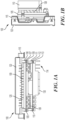
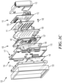
- FIGs. 1A-1C depict graphical representations of an electronic device according to one or more embodiments.
- electronic device 100 is configured with a modular design to provide improved thermal cooling for circuit boards of the electronic device.
- the modular design may also provide improved shielding of circuit boards compared to unshielded arrangements.
- device 100 relates to a vehicle head unit.
- device 100 relates to a vehicle infotainment unit configured to include components for at least one of communication, entertainment, operator interface, driver assistance, guidance and navigation.
- Device 100 may provide one or more functionalities associated with one or more functional units of a vehicle.
- device 100 is described as being associated with a vehicle head unit, it should be appreciated that the principles discussed herein may be applied to other devices and are not limited to vehicle head units.
- device 100 is described as a head unit, which may typically be associated with a vehicle.
- configurations of device 100 are not limited to vehicle devices and are not limited placement in a dashboard or vehicle console.
- device 100 may include additional or separate functions than media playback associated with head units and may include one or more circuit boards to provide at least one function.
- Electronic device 100 may be a head unit for a vehicle and circuit boards of electronic device 100 may be modules for at least one of a media player, navigation unit, radio, communications unit and vehicle interface unit.
- device 100 includes a modular configuration for each circuit board and device 100 may include a plurality of circuit boards.
- each circuit board may be separately housed in a separate module.
- each module includes one circuit board.
- each module can include at least one circuit board.
- device 100 includes multiple modules.
- device 100 may include one or more additional features.
- a circuit board of device 100 may relate to one or more electrical components shared on a single structure, such as a printed circuit board (PCB) or other circuit platforms.
- PCB printed circuit board
- device 100 includes module 105 and module 110 , which may be components of the device.
- Module 105 and module 110 may each include at least one circuit board.
- module 105 includes one circuit board and module 110 includes one circuit board.
- device 100 is described as including module 105 and module 110 , it should be appreciated that modular configuration described herein can include one or more additional modules.
- each module of device 100 may include a chassis enclosure.
- each chassis enclosure includes a front housing and a back housing to retain a circuit board.
- device 100 includes module 105 including front housing 106 and back housing 108 forming a chassis enclosure for circuit board 107 .
- module 110 includes front housing 111 and back housing 113 forming a chassis enclosure for circuit board 112 .
- Chassis enclosures of device 100 may include one or more elements that enclose circuit elements and allow for mounting and securing the enclosure to one or more other enclosures or housing elements.
- each chassis enclosure is structurally connected to another chassis enclosure by fastening elements, such as screws, bolts, threaded connectors, connection pins, etc.
- device 100 is configured with a structure that allows for modules 105 and 110 to be connected with one or more air gaps between chassis enclosures to allow for heat dissipation.
- each module of device 100 may include one or more heat dissipation elements.
- device 100 and modules 105 and 110 may include one or more heat displacement elements, such as heat spreaders 109 within an air gap, such as air gap 125 .
- Air gaps provided by electronic device 100 may provide space between modules for thermal convection (e.g., natural or forced) and increase surface area of the modules to transfer heat in an integrated automotive infotainment head unit.
- modules 105 and 110 of device 100 have a similar structure, such as a substantially planar configuration, wherein module 105 and 110 are joined in an overlapping arrangement along a major face.
- the back housing 108 of module 105 is positioned close to the front housing 111 of module 110 , such that one or more air gaps are provided between module 105 and 110.
- modules 105 and 110 may be secured to a main housing 115 .
- Main housing 115 may be a structural element configured to support a plurality of modules on one side.
- main housing 115 may be configured to support display 120 .
- Main housing 115 may be a main chassis element including a first side structurally connected to the plurality of chassis enclosures and a second side structurally supporting display 120 .
- Main housing 115 may provides shielding of at least one of heat and electromagnetic interference.
- device configurations may employ a front housing a lead chassis module, such as front housing 106 to support a module on one side and support a display on the other side.
- Main housing 115 may allow for mounting device 100 to a supporting structure, such as a vehicle component (e.g., frame, console, dashboard, etc.).
- a vehicle component e.g., frame, console, dashboard, etc.
- the configuration and principles of electronic device 100 does not require coupling to a display.
- electronic device 100 includes a plurality of plurality of chassis enclosures that are each mounted to provide an air gap for heat dissipation.
- Air gap 125 is provided between display 120 and main housing 115 .
- air gap 126 is provided between module 105 and module 110 , and in particular between back housing 108 and front housing 111 .
- Air gaps between chassis enclosures and housings can provide air flow for heat dissipation.
- Display 120 may be mounted to one of the chassis enclosures with an air gap between the display and a chassis enclosure.
- one or more elements of electronic device 100 provide electrical shielding of circuit elements, such as circuit boards 107 and 112 .
- each chassis enclosure is configured to shield a circuit board.
- one or more housing elements may shield circuit boards.
- At least one chassis enclosure of device 100 is configured to provide electromagnetic interference (EMI) shielding to components within the enclosure.
- the chassis enclosures may provide a Faraday cage for circuit boards.
- the chassis enclosures of device 100 may be formed of metallic or other materials to prevent EMI interference between other electrical components of a vehicle and the enclosed circuit board.
- the EMI shielding of device 100 can shielding circuit boards from interference from automotive elements such as motors, vehicle actuator, etc.
- Each chassis enclosure may electrically shield elements in retained circuit board and allow for external connections. Plug elements of a circuit board, such as connection interface 130 out of back housing 113 of module 110 may extend beyond the chassis enclosure to allow for connection to one or more other devices or components.
- chassis enclosures of device 100 may be formed of one or more materials to provide EMI shielding, including but not limited to aluminum (e.g., die-cast, extruded, forged, etc.), magnesium (e.g., die-cast, extruded, forged, etc.), and steel (e.g., cold-rolled sheet metal, etc.). Chassis enclosures of device 100 may be formed with or without gasket materials.
- chassis enclosures of device 100 are formed of a heat sinking material, to provide thermal management. Chassis enclosures may retain a circuit board and transfer heat from the enclosure to one or more air gaps between modules. Chassis enclosures of device 100 may include heat spreaders, such as heat spreaders 109 and heat spreaders 114 , which extend form either a front housing or back housing of the chassis enclosure for heat dissipation.
- Chassis enclosures of device 100 may include heat spreaders, such as heat spreaders 109 and heat spreaders 114 , which extend form either a front housing or back housing of the chassis enclosure for heat dissipation.
- chassis enclosures and circuit boards may be connected to ground contacts integrated within each chassis enclosure.
- FIG. 1 A represents a top down representation of electronic device with modules arranged in parallel with display 120 .
- Each chassis enclosure is mounted in a vertical arrangement (e.g., in parallel with display 120 ). In other embodiments, each chassis enclosure is mounted in a horizontal arrangement (e.g., perpendicular to display 120 ).
- FIG. 1B an alternate view is shown of electronic device 100 .
- the presentation of device 100 in FIG. 1B may be a side profile representation.
- FIG. 1B depicts display 120 mounted to lead side of main housing 115 and a plurality of modules (module 105 and module 110 ) mounted to a trailing side of main housing 115 .
- electronic device 100 may be coupled to a support or vehicle structure such as a console or dash with display 120 facing vehicle passengers.
- Modules 105 and 110 may be within the vehicle structure which may be a compartment within limited airflow.
- One or more air gaps in electronic device 120 such as air gap 125 between module 105 and 110 may allow for improved air flow and heat convection to occur.
- Electronic device 100 may include one or more air gaps not shown in FIG. 1B .
- Electronic device 100 includes one or more features described herein, such as a modular design which can provide improved thermal cooling and EMI shielding for electrical components such as circuit boards of the device. It should also be appreciated that the modular design described herein allows for a compact design and use of material to meet weight requirements for use in a vehicle. Further to being compact, the structure provided allows for thermal cooling while still meeting the requirements for use in a vehicle, such as automobile.
- FIG. 1C a disassembled view is shown for electronic device 100 according to one or more embodiments.
- electronic device 100 includes module 105 having circuit board 108 and module 110 having circuit board 112 .
- Module 105 includes a chassis enclosure provided by front housing 106 and back housing 108 for circuit board 107 .
- module 110 includes a chassis enclosure provided by front housing 111 and back housing 113 for circuit board 112 .
- modules 105 and 110 may be fastened trailing side 117 of main housing 115 by one or more fasteners, such as fastener 145 .
- leading side 116 of main housing 115 may supply display 120 .
- Main housing 115 supports display 130 , display cover 135 and cover plate 140 .
- chassis enclosures of modules 105 and 110 provide EMI shielding for circuit boards and also provide surface areas configured for heat dissipation to air gaps.
- chassis enclosures may include openings for shielded terminals, such as terminal 140 of circuit board 107 and terminal 150 of circuit board 112 that allow for coupling of electronic components.
- electronic device may include fasteners in addition to fastener 145 .
- one or more cables to connections may be made to electronic device 100 .
- principles of the disclosure may be provided to other structures with different shapes and features.
- features described herein may be applied to electronic head units that do not include a main housing 115 .
- features and elements described herein could be employed on an electronic device that is not mounted in proximity to the display, such as an infotainment unit with a flip out display or remotely located display.
- modules 105 may utilize main housing 115 as a front housing for circuit board 107 , such that main housing 115 and back housing 108 form a chassis enclosure for circuit board 107 .
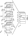
- FIG. 2 depicts a simplified diagram of an electronic device according to one or more embodiments. According to one embodiment, configurations and features are provided for a plurality of modules to improve thermal cooling and shielding of circuit board components associated with each module.
- FIG. 2 depicts a simplified representation of an electronic device and device features according to one or more embodiments.
- FIG. 2 depicts both disassembled and assembled representations of an electronic device 200 .
- Electronic device 200 may relate to electronic components for a vehicle, such as a vehicle head unit, vehicle infotainment unit, etc.
- device 200 includes a series of modules 205 1-n .
- Modules 205 1-n may each include a circuit board, shown as circuit boards 210 1-n .
- each of the circuit boards 210 1-n may be enclosed within a chassis enclosure formed by a front housing and a back housing, such as front housings 210 1-n and back housings 210 1-n .
- Device 200 may optionally include main housing 225 configured to support a display 220 and modules 205 1-n .
- circuit boards 210 1-n may be sized smaller than front housings 210 1-n and back housings 210 1-n to allow for enclosing the circuit boards.
- Each of the front housings 210 1-n may be paired with one of the back housings 210 1-n , to form a chassis enclosure configured to operate as a Faraday cage to provide EMI shielding for a circuit board retained within the front and back housing.
- the front housings 210 1-n and back housings 210 1-n can include a ground connection along an outer periphery of the housings.
- front housings 210 1-n and back housings 210 1-n may be substantially planar elements to provide a surface area for exchange of heat within air gaps so that heat may be radiated out from electronic device as shown by directions 230 , 235 and 240 .
- radiation of heat may be provided by air gaps between modules 205 1-n .
- One benefit of a substantially planar chassis enclosure may be providing an increased surface area to allow for thermal convection in air gaps in comparison to non-modular configurations.
- front housings 210 1-n and back housings 210 1-n may also include one or more features, such as raised fins or heat spreaders to radiate heat.
- electronic device 200 may couple modules 205 1-n to main housing 225 and display 220 as shown by configuration 245 .
- Each chassis enclosure is structurally connected to another chassis enclosure by fastening elements.
- electronic device 200 when assembled in configuration 245 includes air gaps between modules 205 1-n . Air gaps may also be provided between main housing 225 and module 205 1 . Similarly, air gaps may be provided between display 220 and main housing 225 . According to one embodiment, air gaps may be on lateral portions, such as left side 255 and/or top and bottom portions, such as top interface 250 , of configuration 245 .
- each module of electronic device 200 may be separated from each other, with the exception of mounting or coupling points, such that an air gap is provided between each successive pairing of modules 205 1-n .
- the air gap between modules 205 1-n may range and vary between each set of modules.
- each module and chassis enclosure is mounted in a vertical arrangement (e.g., in parallel with display 220 ). In other embodiments, each chassis enclosure is mounted in a horizontal arrangement (e.g., perpendicular to display 220 ).
- Each chassis enclosure may be formed of a heat sinking material and include one or more heat spreading elements of the extending into an air gap between modules.
- FIG. 3 depicts a graphical representation of an electronic device according to one or more embodiments.
- a disassembled view is shown for electronic device 300 according to one or more embodiments.
- Electronic device 300 includes module 305 having circuit board 307 and module 310 having circuit board 312 .
- Module 105 includes a chassis enclosure provided by front housing 306 and back housing 308 for circuit board 307 .
- module 310 includes a chassis enclosure provided by front housing 311 and back housing 313 for circuit board 312 .
- components of modules 305 and 310 may be fastened together to trailing side 309 of front housing 306 by one or more fasteners, such as fastener 315 .
- a leading side housing 306 may support optional components 320 .
- Optional components 320 may relate to circuit board 325 and front cover 330 which may be mounted to front housing 306 to support a display, such as a touch screen display or other components.
- one or more portions of electronic device 300 may be cooled and/or regulated by liquid cooling elements.
- electronic device 300 may include one or more liquid cooling features.
- embedded channels may be built into circuit boards (e.g., circuit boards 307 and 312 ) and housings (e.g., front housing 306 and 311 and back housings 308 and 313 ).
- liquid cooling elements of electronic device 300 may be provided by fluid exchange with components such as within the heat spreaders of the housing elements.
- Electronic device 300 may interface with an ambient exchange element to provide liquid cooling according to one or more embodiments.
- liquid cooling elements of electronic device 300 may include at least one of a passive configuration (e.g., use of a heat pipe, etc.), and active configuration (e.g., use of a pumps and heat exchangers, etc.).
- Liquid cooling elements may be included within and external to enclosures.
- one or more of a heat pipe, cold plate, passive system, and active system may additionally circulate heat associated with a module.
- front housing 306 and one or more other elements of device 300 may include a ground elements.
- Ground 350 is positioned along an outer perimeter of trailing edge of front housing 306 to provide a ground connection.
- Each of the modules of device 300 such as front housing 306 and back housing 308 for circuit board 307 and front housing 311 and back housing 313 for circuit board 312 , may include a ground element, similar to ground element 350 , between the front housing and the back housing of each enclosure to provide a ground connection along an outer periphery of a retained circuit board.
- ground 350 may be provided by one or more ground holes in each circuit board, the ground holes connected to a chassis.
- Electrical ground connections of modules may also include a contact having a low electrical resistance (e.g., friction contact, fastener, etc.).
- a contact having a low electrical resistance e.g., friction contact, fastener, etc.
Landscapes
- Engineering & Computer Science (AREA)
- Microelectronics & Electronic Packaging (AREA)
- Physics & Mathematics (AREA)
- Thermal Sciences (AREA)
- Chemical & Material Sciences (AREA)
- Combustion & Propulsion (AREA)
- Transportation (AREA)
- Mechanical Engineering (AREA)
- Shielding Devices Or Components To Electric Or Magnetic Fields (AREA)
- Cooling Or The Like Of Electrical Apparatus (AREA)
Claims (10)
- Elektronisches Gerät (100; 200; 300), umfassend:ein Display (120; 220);eine Vielzahl von Leiterplatten (107, 112; 210 1-n; 307, 312);ein Hauptgehäuseelement (115), das konfiguriert ist, um das Display (120; 220) zu unterstützen; undeine Vielzahl von Chassisgehäusen, wobei jede der Vielzahl von Leiterplatten (107, 112; 210 1-n; 307, 312) separat von einem Chassisgehäuse untergebracht ist, und wobei jedes Chassisgehäuse enthältein vorderes Gehäuse (106, 111; 306, 311) und ein hinteres Gehäuse (108, 113; 308, 313), wobei das vordere Gehäuse (106, 111; 306, 311) und das hintere Gehäuse (108, 113; 308, 313) konfiguriert sind, um eine Leiterplatte (107, 112; 210 1-n; 307, 312) zurückzuhalten, undmindestens ein Wärmeabführungselement,wobei die Vielzahl von Chassisgehäusen montiert ist, um einen Luftspalt (126) zur Wärmeableitung zwischen jedem Chassisgehäuse bereitzustellen, wobei jedes Chassisgehäuse aus einem wärmeableitenden Material gebildet ist und wobei sich ein oder mehrere Wärmeverteilungselemente des Chassisgehäuses in den Luftspalt (126) zwischen Chassisgehäusen erstreckt,wobei jedes Chassisgehäuse eine zurückgehaltene Leiterplatte (107, 112; 210 1-n; 307, 312) elektrisch abschirmt, undwobei die Wärmeausbreitungselemente in dem Luftspalt (126) zwischen zwei Chassisgehäusen voneinander getrennt sind.
- Elektronisches Gerät (100; 200; 300) nach Anspruch 1, wobei mindestens eines von:jedes Chassisgehäuse mit einem anderen Chassisgehäuse durch Befestigungselemente (145) strukturell verbunden ist; undjedes Chassisgehäuse in mindestens einer von einer vertikalen Anordnung und einer horizontalen Anordnung montiert ist.
- Elektronisches Gerät (100; 200; 300) nach Anspruch 1, wobei das vordere Gehäuse (106, 111; 306, 311) und das hintere Gehäuse (108, 113; 308, 313) eines Chassisgehäuses konfiguriert sind, um wie ein Faradayscher Käfig zu wirken, um eine EMI-Abschirmung bereitzustellen.
- Elektronisches Gerät (100; 200; 300) nach Anspruch 1, wobei das vordere Gehäuse (106, 111; 306, 311) und das hintere Gehäuse (108, 113; 308, 313) jedes Gehäuses entlang eines äußeren Umfangs einer zurückgehaltenen Leiterplatte (107, 112; 210 1-n; 307, 312) eine Masseverbindung aufweisen.
- Elektronisches Gerät (100; 200; 300) nach Anspruch 1, wobei das elektronische Gerät (100; 200; 300) eine Kopfeinheit für ein Fahrzeug ist und Leiterplatten (107, 112; 210 1-n; 307, 312) des elektronischen Geräts (100; 200; 300) Module für mindestens eines von einem Mediaplayer, einer Navigationseinheit, einem Radio, einer Kommunikationseinheit und einer Fahrzeugschnittstelleneinheit sind.
- Elektronisches Gerät (100; 200; 300) nach Anspruch 1, wobei das Display (120; 220) ein Touchscreen-Display ist, das zum Betreiben durch mindestens eine der Vielzahl von Leiterplatten (107, 112; 210 1-n; 307, 312) konfiguriert ist.
- Elektronisches Gerät (100; 200; 300) nach Anspruch 1, ferner umfassend ein flüssigkeitsgekühltes Element für mindestens eines der Chassisgehäuse.
- Elektronisches Gerät (100; 200; 300) nach Anspruch 1, wobei das Hauptchassiselement (115) eine erste Seite, die strukturell mit der Vielzahl von Chassisgehäusen verbunden ist, und eine zweite Seite, die strukturell das Display (120; 220) trägt, umfasst.
- Elektronisches Gerät (100; 200; 300) nach Anspruch 8, wobei das Hauptchassiselement (115) eine Abschirmung von mindestens einem von Wärme und elektromagnetischen Störungen bereitstellt.
- Elektronisches Gerät (100; 200; 300) nach Anspruch 1, wobei das Display (120; 220) an einem der Chassisgehäuse montiert ist, und wobei ein Montieren des Displays (120; 220) einen Luftspalt (125) zwischen dem Display (120; 220) und einem Chassisgehäuse bereitstellt.
Applications Claiming Priority (1)
| Application Number | Priority Date | Filing Date | Title |
|---|---|---|---|
| US15/714,858 US10278313B2 (en) | 2017-09-25 | 2017-09-25 | Modular electronic device and head unit for vehicles |
Publications (2)
| Publication Number | Publication Date |
|---|---|
| EP3461249A1 EP3461249A1 (de) | 2019-03-27 |
| EP3461249B1 true EP3461249B1 (de) | 2024-10-30 |
Family
ID=63683021
Family Applications (1)
| Application Number | Title | Priority Date | Filing Date |
|---|---|---|---|
| EP18196182.2A Active EP3461249B1 (de) | 2017-09-25 | 2018-09-24 | Modulare elektronische vorrichtung und kopfeinheit für fahrzeuge |
Country Status (3)
| Country | Link |
|---|---|
| US (1) | US10278313B2 (de) |
| EP (1) | EP3461249B1 (de) |
| CN (1) | CN109587978B (de) |
Families Citing this family (5)
| Publication number | Priority date | Publication date | Assignee | Title |
|---|---|---|---|---|
| WO2020262739A1 (ko) | 2019-06-28 | 2020-12-30 | 엘지전자 주식회사 | Avn 장치 |
| DE102020208053A1 (de) * | 2020-04-03 | 2021-10-07 | Volkswagen Aktiengesellschaft | Fahrzeug, zentrale recheneinheit, module, herstellungsverfahren und fahrzeug, kühllamelle, taschenmodul, hauptrahmen |
| CN115299186A (zh) | 2020-04-03 | 2022-11-04 | 大众汽车股份公司 | 载具、主框架、模块凹处、电子模块和印刷电路板 |
| US12363874B2 (en) | 2020-04-03 | 2025-07-15 | Volkswagen Aktiengesellschaft | Vehicle and main frame for mounting and connecting vehicular components |
| CN113823932B (zh) * | 2020-06-18 | 2025-07-18 | 莫列斯有限公司 | 连接器组件 |
Citations (2)
| Publication number | Priority date | Publication date | Assignee | Title |
|---|---|---|---|---|
| US4771365A (en) * | 1987-10-30 | 1988-09-13 | Honeywell Inc. | Passive cooled electronic chassis |
| US20090122500A1 (en) * | 2007-11-12 | 2009-05-14 | Metzger Thomas R | Card Level Enclosure System Having Enhanced Thermal Transfer And Improved EMI Characteristics |
Family Cites Families (9)
| Publication number | Priority date | Publication date | Assignee | Title |
|---|---|---|---|---|
| US5506373A (en) * | 1993-07-09 | 1996-04-09 | Magnavox Electronic Systems Company | Electronic module enclosure |
| TW410023U (en) * | 1998-09-05 | 2000-10-21 | Inventec Corp | Horizontal lying object supporting assembling device |
| US6661657B1 (en) * | 2002-02-14 | 2003-12-09 | Mercury Computer Systems, Inc. | Circuit board assembly for use in a central inlet chassis configuration |
| US7365974B2 (en) * | 2005-10-14 | 2008-04-29 | Smiths Aerospace Llc | Method for electronics equipment cooling having improved EMI control and reduced weight |
| CA2666014C (en) * | 2009-05-15 | 2016-08-16 | Ruggedcom Inc. | Open frame electronic chassis for enclosed modules |
| KR101873407B1 (ko) * | 2011-07-13 | 2018-07-02 | 엘지전자 주식회사 | 이동 단말기 |
| TWM441311U (en) * | 2012-06-08 | 2012-11-11 | Leng-Hong Zhang | Casing formed with heat sink combination |
| JP6123604B2 (ja) * | 2013-09-20 | 2017-05-10 | 株式会社デンソー | 車両の端末設置構造 |
| KR102583890B1 (ko) * | 2016-02-18 | 2023-10-05 | 삼성전자주식회사 | 열 수집/확산 구조를 가진 전자 장치 |
-
2017
- 2017-09-25 US US15/714,858 patent/US10278313B2/en active Active
-
2018
- 2018-09-19 CN CN201811092066.2A patent/CN109587978B/zh active Active
- 2018-09-24 EP EP18196182.2A patent/EP3461249B1/de active Active
Patent Citations (2)
| Publication number | Priority date | Publication date | Assignee | Title |
|---|---|---|---|---|
| US4771365A (en) * | 1987-10-30 | 1988-09-13 | Honeywell Inc. | Passive cooled electronic chassis |
| US20090122500A1 (en) * | 2007-11-12 | 2009-05-14 | Metzger Thomas R | Card Level Enclosure System Having Enhanced Thermal Transfer And Improved EMI Characteristics |
Also Published As
| Publication number | Publication date |
|---|---|
| CN109587978A (zh) | 2019-04-05 |
| US20190098800A1 (en) | 2019-03-28 |
| CN109587978B (zh) | 2021-07-20 |
| EP3461249A1 (de) | 2019-03-27 |
| US10278313B2 (en) | 2019-04-30 |
Similar Documents
| Publication | Publication Date | Title |
|---|---|---|
| EP3461249B1 (de) | Modulare elektronische vorrichtung und kopfeinheit für fahrzeuge | |
| EP3090611B1 (de) | Verfahren und vorrichtung zur erhöhung der wärmeverstärkungskapazität eines hutschienenmontierten gehäuses | |
| CN110062719B (zh) | 多媒体控制单元的散热装置 | |
| EP1198978B1 (de) | Herstellungsverfahren eines elektronischen leiterplattenmodul mit wärmeableitung unter benutzung von einer konvektionsgekühlten leiterplatter | |
| JP2020055413A (ja) | 車両用表示装置 | |
| US6669273B1 (en) | Vehicle instrument panel structure to support electronics packaging | |
| CN110568910A (zh) | 车用主机及车用计算机系统 | |
| CA2954343C (en) | Display unit for vehicle and display control unit | |
| JP5041548B2 (ja) | 電力制御装置 | |
| KR101360730B1 (ko) | 방열 장치 및 이를 포함하는 전기 장치 | |
| EP4322720B1 (de) | Systeme und verfahren für eine elektronische vorrichtung | |
| CN113939132B (zh) | 一种层叠式车载主机结构 | |
| CN117498476A (zh) | 一种无线充电组件 | |
| EP1865758B1 (de) | Metallkernsubstrat-verstärkungsstruktur und elektrische verbindungsbox | |
| EP3898307B1 (de) | Fahrzeuganzeigeträger mit kühlkörper | |
| JP2017151381A (ja) | 表示装置 | |
| JP2006120794A (ja) | 電子機器 | |
| KR101063172B1 (ko) | 전자제어장치 | |
| CN223843990U (zh) | 一种域控制器及车辆 | |
| CN223007783U (zh) | 一种车载屏一体机及汽车 | |
| CN218735737U (zh) | 散热结构以及电子设备 | |
| CN223714309U (zh) | 电子控制装置、倒车影像系统和车辆 | |
| CN221381607U (zh) | 一种车载域控主机 | |
| CN224124371U (zh) | 一种信号检测器的机箱外壳 | |
| CN215222729U (zh) | 伺服驱动器 |
Legal Events
| Date | Code | Title | Description |
|---|---|---|---|
| PUAI | Public reference made under article 153(3) epc to a published international application that has entered the european phase |
Free format text: ORIGINAL CODE: 0009012 |
|
| STAA | Information on the status of an ep patent application or granted ep patent |
Free format text: STATUS: THE APPLICATION HAS BEEN PUBLISHED |
|
| AK | Designated contracting states |
Kind code of ref document: A1 Designated state(s): AL AT BE BG CH CY CZ DE DK EE ES FI FR GB GR HR HU IE IS IT LI LT LU LV MC MK MT NL NO PL PT RO RS SE SI SK SM TR |
|
| AX | Request for extension of the european patent |
Extension state: BA ME |
|
| STAA | Information on the status of an ep patent application or granted ep patent |
Free format text: STATUS: REQUEST FOR EXAMINATION WAS MADE |
|
| 17P | Request for examination filed |
Effective date: 20190927 |
|
| RBV | Designated contracting states (corrected) |
Designated state(s): AL AT BE BG CH CY CZ DE DK EE ES FI FR GB GR HR HU IE IS IT LI LT LU LV MC MK MT NL NO PL PT RO RS SE SI SK SM TR |
|
| STAA | Information on the status of an ep patent application or granted ep patent |
Free format text: STATUS: EXAMINATION IS IN PROGRESS |
|
| 17Q | First examination report despatched |
Effective date: 20210326 |
|
| GRAP | Despatch of communication of intention to grant a patent |
Free format text: ORIGINAL CODE: EPIDOSNIGR1 |
|
| STAA | Information on the status of an ep patent application or granted ep patent |
Free format text: STATUS: GRANT OF PATENT IS INTENDED |
|
| RIC1 | Information provided on ipc code assigned before grant |
Ipc: H05K 5/00 20060101ALI20240508BHEP Ipc: H05K 9/00 20060101ALI20240508BHEP Ipc: H05K 7/20 20060101AFI20240508BHEP |
|
| INTG | Intention to grant announced |
Effective date: 20240524 |
|
| GRAS | Grant fee paid |
Free format text: ORIGINAL CODE: EPIDOSNIGR3 |
|
| GRAA | (expected) grant |
Free format text: ORIGINAL CODE: 0009210 |
|
| STAA | Information on the status of an ep patent application or granted ep patent |
Free format text: STATUS: THE PATENT HAS BEEN GRANTED |
|
| AK | Designated contracting states |
Kind code of ref document: B1 Designated state(s): AL AT BE BG CH CY CZ DE DK EE ES FI FR GB GR HR HU IE IS IT LI LT LU LV MC MK MT NL NO PL PT RO RS SE SI SK SM TR |
|
| REG | Reference to a national code |
Ref country code: GB Ref legal event code: FG4D |
|
| REG | Reference to a national code |
Ref country code: CH Ref legal event code: EP |
|
| P01 | Opt-out of the competence of the unified patent court (upc) registered |
Free format text: CASE NUMBER: APP_53162/2024 Effective date: 20240924 |
|
| REG | Reference to a national code |
Ref country code: IE Ref legal event code: FG4D |
|
| REG | Reference to a national code |
Ref country code: DE Ref legal event code: R096 Ref document number: 602018075919 Country of ref document: DE |
|
| REG | Reference to a national code |
Ref country code: LT Ref legal event code: MG9D |
|
| REG | Reference to a national code |
Ref country code: NL Ref legal event code: MP Effective date: 20241030 |
|
| PG25 | Lapsed in a contracting state [announced via postgrant information from national office to epo] |
Ref country code: IS Free format text: LAPSE BECAUSE OF FAILURE TO SUBMIT A TRANSLATION OF THE DESCRIPTION OR TO PAY THE FEE WITHIN THE PRESCRIBED TIME-LIMIT Effective date: 20250228 Ref country code: HR Free format text: LAPSE BECAUSE OF FAILURE TO SUBMIT A TRANSLATION OF THE DESCRIPTION OR TO PAY THE FEE WITHIN THE PRESCRIBED TIME-LIMIT Effective date: 20241030 Ref country code: PT Free format text: LAPSE BECAUSE OF FAILURE TO SUBMIT A TRANSLATION OF THE DESCRIPTION OR TO PAY THE FEE WITHIN THE PRESCRIBED TIME-LIMIT Effective date: 20250228 |
|
| PG25 | Lapsed in a contracting state [announced via postgrant information from national office to epo] |
Ref country code: FI Free format text: LAPSE BECAUSE OF FAILURE TO SUBMIT A TRANSLATION OF THE DESCRIPTION OR TO PAY THE FEE WITHIN THE PRESCRIBED TIME-LIMIT Effective date: 20241030 Ref country code: NL Free format text: LAPSE BECAUSE OF FAILURE TO SUBMIT A TRANSLATION OF THE DESCRIPTION OR TO PAY THE FEE WITHIN THE PRESCRIBED TIME-LIMIT Effective date: 20241030 |
|
| REG | Reference to a national code |
Ref country code: AT Ref legal event code: MK05 Ref document number: 1738234 Country of ref document: AT Kind code of ref document: T Effective date: 20241030 |
|
| PG25 | Lapsed in a contracting state [announced via postgrant information from national office to epo] |
Ref country code: BG Free format text: LAPSE BECAUSE OF FAILURE TO SUBMIT A TRANSLATION OF THE DESCRIPTION OR TO PAY THE FEE WITHIN THE PRESCRIBED TIME-LIMIT Effective date: 20241030 |
|
| PG25 | Lapsed in a contracting state [announced via postgrant information from national office to epo] |
Ref country code: ES Free format text: LAPSE BECAUSE OF FAILURE TO SUBMIT A TRANSLATION OF THE DESCRIPTION OR TO PAY THE FEE WITHIN THE PRESCRIBED TIME-LIMIT Effective date: 20241030 |
|
| PG25 | Lapsed in a contracting state [announced via postgrant information from national office to epo] |
Ref country code: NO Free format text: LAPSE BECAUSE OF FAILURE TO SUBMIT A TRANSLATION OF THE DESCRIPTION OR TO PAY THE FEE WITHIN THE PRESCRIBED TIME-LIMIT Effective date: 20250130 |
|
| PG25 | Lapsed in a contracting state [announced via postgrant information from national office to epo] |
Ref country code: LV Free format text: LAPSE BECAUSE OF FAILURE TO SUBMIT A TRANSLATION OF THE DESCRIPTION OR TO PAY THE FEE WITHIN THE PRESCRIBED TIME-LIMIT Effective date: 20241030 Ref country code: GR Free format text: LAPSE BECAUSE OF FAILURE TO SUBMIT A TRANSLATION OF THE DESCRIPTION OR TO PAY THE FEE WITHIN THE PRESCRIBED TIME-LIMIT Effective date: 20250131 Ref country code: AT Free format text: LAPSE BECAUSE OF FAILURE TO SUBMIT A TRANSLATION OF THE DESCRIPTION OR TO PAY THE FEE WITHIN THE PRESCRIBED TIME-LIMIT Effective date: 20241030 |
|
| PG25 | Lapsed in a contracting state [announced via postgrant information from national office to epo] |
Ref country code: PL Free format text: LAPSE BECAUSE OF FAILURE TO SUBMIT A TRANSLATION OF THE DESCRIPTION OR TO PAY THE FEE WITHIN THE PRESCRIBED TIME-LIMIT Effective date: 20241030 |
|
| PG25 | Lapsed in a contracting state [announced via postgrant information from national office to epo] |
Ref country code: RS Free format text: LAPSE BECAUSE OF FAILURE TO SUBMIT A TRANSLATION OF THE DESCRIPTION OR TO PAY THE FEE WITHIN THE PRESCRIBED TIME-LIMIT Effective date: 20250130 |
|
| PG25 | Lapsed in a contracting state [announced via postgrant information from national office to epo] |
Ref country code: SM Free format text: LAPSE BECAUSE OF FAILURE TO SUBMIT A TRANSLATION OF THE DESCRIPTION OR TO PAY THE FEE WITHIN THE PRESCRIBED TIME-LIMIT Effective date: 20241030 |
|
| PG25 | Lapsed in a contracting state [announced via postgrant information from national office to epo] |
Ref country code: DK Free format text: LAPSE BECAUSE OF FAILURE TO SUBMIT A TRANSLATION OF THE DESCRIPTION OR TO PAY THE FEE WITHIN THE PRESCRIBED TIME-LIMIT Effective date: 20241030 |
|
| PG25 | Lapsed in a contracting state [announced via postgrant information from national office to epo] |
Ref country code: EE Free format text: LAPSE BECAUSE OF FAILURE TO SUBMIT A TRANSLATION OF THE DESCRIPTION OR TO PAY THE FEE WITHIN THE PRESCRIBED TIME-LIMIT Effective date: 20241030 |
|
| PG25 | Lapsed in a contracting state [announced via postgrant information from national office to epo] |
Ref country code: RO Free format text: LAPSE BECAUSE OF FAILURE TO SUBMIT A TRANSLATION OF THE DESCRIPTION OR TO PAY THE FEE WITHIN THE PRESCRIBED TIME-LIMIT Effective date: 20241030 |
|
| PG25 | Lapsed in a contracting state [announced via postgrant information from national office to epo] |
Ref country code: SK Free format text: LAPSE BECAUSE OF FAILURE TO SUBMIT A TRANSLATION OF THE DESCRIPTION OR TO PAY THE FEE WITHIN THE PRESCRIBED TIME-LIMIT Effective date: 20241030 |
|
| PG25 | Lapsed in a contracting state [announced via postgrant information from national office to epo] |
Ref country code: CZ Free format text: LAPSE BECAUSE OF FAILURE TO SUBMIT A TRANSLATION OF THE DESCRIPTION OR TO PAY THE FEE WITHIN THE PRESCRIBED TIME-LIMIT Effective date: 20241030 |
|
| PG25 | Lapsed in a contracting state [announced via postgrant information from national office to epo] |
Ref country code: IT Free format text: LAPSE BECAUSE OF FAILURE TO SUBMIT A TRANSLATION OF THE DESCRIPTION OR TO PAY THE FEE WITHIN THE PRESCRIBED TIME-LIMIT Effective date: 20241030 |
|
| REG | Reference to a national code |
Ref country code: DE Ref legal event code: R097 Ref document number: 602018075919 Country of ref document: DE |
|
| PLBE | No opposition filed within time limit |
Free format text: ORIGINAL CODE: 0009261 |
|
| STAA | Information on the status of an ep patent application or granted ep patent |
Free format text: STATUS: NO OPPOSITION FILED WITHIN TIME LIMIT |
|
| PG25 | Lapsed in a contracting state [announced via postgrant information from national office to epo] |
Ref country code: SE Free format text: LAPSE BECAUSE OF FAILURE TO SUBMIT A TRANSLATION OF THE DESCRIPTION OR TO PAY THE FEE WITHIN THE PRESCRIBED TIME-LIMIT Effective date: 20241030 |
|
| 26N | No opposition filed |
Effective date: 20250731 |
|
| PGFP | Annual fee paid to national office [announced via postgrant information from national office to epo] |
Ref country code: DE Payment date: 20250820 Year of fee payment: 8 |
|
| PGFP | Annual fee paid to national office [announced via postgrant information from national office to epo] |
Ref country code: GB Payment date: 20250820 Year of fee payment: 8 |