EP3461049B1 - Verfahren und entsprechendes endgerät zur datenverarbeitung - Google Patents
Verfahren und entsprechendes endgerät zur datenverarbeitung Download PDFInfo
- Publication number
- EP3461049B1 EP3461049B1 EP17812479.8A EP17812479A EP3461049B1 EP 3461049 B1 EP3461049 B1 EP 3461049B1 EP 17812479 A EP17812479 A EP 17812479A EP 3461049 B1 EP3461049 B1 EP 3461049B1
- Authority
- EP
- European Patent Office
- Prior art keywords
- terminal
- module
- data
- spreading
- preprocessing operation
- Prior art date
- Legal status (The legal status is an assumption and is not a legal conclusion. Google has not performed a legal analysis and makes no representation as to the accuracy of the status listed.)
- Active
Links
Images


Classifications
-
- H—ELECTRICITY
- H04—ELECTRIC COMMUNICATION TECHNIQUE
- H04L—TRANSMISSION OF DIGITAL INFORMATION, e.g. TELEGRAPHIC COMMUNICATION
- H04L5/00—Arrangements affording multiple use of the transmission path
- H04L5/0001—Arrangements for dividing the transmission path
- H04L5/0003—Two-dimensional division
- H04L5/0005—Time-frequency
-
- H—ELECTRICITY
- H04—ELECTRIC COMMUNICATION TECHNIQUE
- H04L—TRANSMISSION OF DIGITAL INFORMATION, e.g. TELEGRAPHIC COMMUNICATION
- H04L1/00—Arrangements for detecting or preventing errors in the information received
- H04L1/0001—Systems modifying transmission characteristics according to link quality, e.g. power backoff
- H04L1/0002—Systems modifying transmission characteristics according to link quality, e.g. power backoff by adapting the transmission rate
- H04L1/0003—Systems modifying transmission characteristics according to link quality, e.g. power backoff by adapting the transmission rate by switching between different modulation schemes
-
- H—ELECTRICITY
- H04—ELECTRIC COMMUNICATION TECHNIQUE
- H04L—TRANSMISSION OF DIGITAL INFORMATION, e.g. TELEGRAPHIC COMMUNICATION
- H04L27/00—Modulated-carrier systems
- H04L27/32—Carrier systems characterised by combinations of two or more of the types covered by groups H04L27/02, H04L27/10, H04L27/18 or H04L27/26
- H04L27/34—Amplitude- and phase-modulated carrier systems, e.g. quadrature-amplitude modulated carrier systems
- H04L27/3405—Modifications of the signal space to increase the efficiency of transmission, e.g. reduction of the bit error rate, bandwidth, or average power
- H04L27/3444—Modifications of the signal space to increase the efficiency of transmission, e.g. reduction of the bit error rate, bandwidth, or average power by applying a certain rotation to regular constellations
-
- H—ELECTRICITY
- H04—ELECTRIC COMMUNICATION TECHNIQUE
- H04L—TRANSMISSION OF DIGITAL INFORMATION, e.g. TELEGRAPHIC COMMUNICATION
- H04L5/00—Arrangements affording multiple use of the transmission path
- H04L5/0001—Arrangements for dividing the transmission path
-
- H—ELECTRICITY
- H04—ELECTRIC COMMUNICATION TECHNIQUE
- H04L—TRANSMISSION OF DIGITAL INFORMATION, e.g. TELEGRAPHIC COMMUNICATION
- H04L5/00—Arrangements affording multiple use of the transmission path
- H04L5/003—Arrangements for allocating sub-channels of the transmission path
-
- H—ELECTRICITY
- H04—ELECTRIC COMMUNICATION TECHNIQUE
- H04W—WIRELESS COMMUNICATION NETWORKS
- H04W52/00—Power management, e.g. Transmission Power Control [TPC] or power classes
- H04W52/04—Transmission power control [TPC]
- H04W52/30—Transmission power control [TPC] using constraints in the total amount of available transmission power
- H04W52/32—TPC of broadcast or control channels
- H04W52/325—Power control of control or pilot channels
Definitions
- Embodiments of this application relate to the field of communications technologies, and more specifically, to a data processing method.
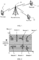
- the existing LTE system includes a plurality of cells.
- Each cell includes one network device 11 (such as a base station) and a plurality of terminals 12.
- the network device 11 sends, to the terminals 12, public control information and data, and a reference signal used for detecting the public control information and data.
- the network device sends a signal to the terminal by using an independent resource and the terminal sends a signal to the network device also by using an independent resource.
- the two independent resources may be a same time point but different frequencies (namely, FDD), or a same frequency but different time points (namely, TDD).
- a multiple access technology is developed in the industry.
- the technology also becomes one of core technologies of a wireless communication physical layer, enabling a wireless network device to distinguish and simultaneously serve a plurality of terminals, and further reducing mutual interference (for example, multiple access interference) between the plurality of terminals.
- Most existing wireless communications systems use a simple orthogonal multiple access technology.
- a plurality of terminals access a system by orthogonally dividing resources in different dimensions (frequency division, time division, code division, or the like).
- an OFDMA multiple access technology currently used in the LTE system is one of orthogonal multiple access technologies.
- a quantity of access terminals that can be accommodated in the orthogonal multiple access technology is in direct proportion to orthogonal resources, and a quantity of the orthogonal resources is limited by an orthogonal requirement. Therefore, service requirements such as continuous coverage in a large range in a future 5G network, large-capacity and large-scale connectivity in a hotspot area, and ultra-low latency access cannot be satisfied.
- TAO YUNZHENG ET AL "A survey: Several technologies of non-orthogonal transmission for 5G", CHINA COMMUNICATIONS, CHINA INSTITUTE OF COMMUNICATIONS, vol. 12, no. 10, ISSN 1673-5447, pages 1 - 15 , is teaches different techniques for implementing non-orthogonal transmission for 5G communication systems.
- Embodiments of this application provide a data processing method and a device.
- the present invention is defined by a data processing method according to independent claim 1 and by a terminal according to independent claim 7. Additional features of the invention are provided in the dependent claims.
- parts of the description and drawings referring to embodiments and/or aspects (of the invention and/or application and/or disclosure) which are not covered by the claims are not presented as embodiments of the invention, but as examples useful for understanding the invention.
- the present invention is defined by the appended claims and limited only by their scope.
- an embodiment of this application provides a data processing method, including the steps of claim 1 and further detailed in the dependent claims referring back to this claim.
- a second aspect of the present invention relates to a terminal according to claim 7 and further detailed in the dependent claims referring back to this claim.
- non-orthogonal spreading and superposition transmission of a plurality of terminals can be implemented in both uplink and downlink, thereby effectively improving transmission efficiency.
- one network device may communicate with a plurality of terminals.
- a non-orthogonal technology may be used for communication between a terminal and a network device.
- the network device herein may be a base station, or may be another network side device having a function similar to that of the base station.
- the embodiments of this application provide a data processing method.
- the data processing method is performed by the network device.
- the method may be performed by one of the terminals.
- communication between a network device and a terminal is used as an example for description.
- the network device In downlink transmission, the network device is used as a transmit end.
- uplink transmission the terminal is used as a transmit end.
- An SCMA technology is a typical non-orthogonal multiple access and transmission technology, in which a total of G layers of data streams of N terminals (where N and G are integers not less than 1, and N ⁇ G) are superposed to Q (where Q is an integer not less than 1, and usually, G>Q) REs (which are minimum granularities for time-frequency resource allocation) for sending.
- Each data symbol of each layer of data stream is extended to the Q REs in a sparse spreading method.
- the Q REs may be Q consecutive subcarriers in a same symbol, or may be Q consecutive symbols on a same subcarrier, or may be Q consecutive REs in another form.
- This type of technology can effectively increase a network capacity, including a quantity of terminals that can access a system, spectrum efficiency, and the like.
- an encoded bit is modulated into a corresponding multi-dimensional symbol by using a codebook prestored at each data layer and is mapped to an RE at a corresponding location.
- the codebook includes both multi-dimensional modulation symbol information and a spreading rule. Therefore, a codebook design has crucial impact on system performance (especially downlink performance) using the SCMA technology.
- An LDS technology is similar to the SCMA technology except that symbols sent by a terminal on different REs are not multi-dimensional modulation symbols but repeated QAM symbols. For downlink transmission in the SCMA and LDS, angle rotation needs to be performed on symbols of a non-orthogonal data layer of equal power to ensure unique solvability of superposed symbols.
- MUSA is a non-orthogonal multiple access solution in code domain.
- a predesigned sequence (with a low cross-correlation) is used for spreading of a data symbol, making it easy for a receive end to use a SIC receiving mode.
- superposed transmission is performed on spreading symbols of all terminals on a same spectrum resource, and a codeword-level SIC receiver is used on a receive end of the spreading symbols.
- a non-binary spreading sequence is used in MUSA uplink, and this is non-sparse spreading.
- There is a power difference between symbols in a same group in MUSA downlink and it is ensured that superposed symbols comply with a modulation rule of a Gray constellation.
- PDMA is a non-orthogonal access solution that further increases a system capacity by introducing diversity between terminals.
- a PDMA terminal uses a non-orthogonal transmission pattern in time, frequency, space, code domain, and other dimensions.
- a BP-IDD algorithm may be used.
- a spreading method of the PDMA is different from that of the SCMA.
- Regular spreading herein means that spreading factors (or referred to as spreading multiples) of all layers of data are consistent.
- the irregular spreading means that all layers of data have respective independent spreading factors.
- a modulation symbol of the PDMA is also a common QAM symbol, and a transmission symbol of the PDMA is also generated in a form similar to an SCMA codebook.
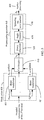
- FIG. 3 is a schematic flowchart of modulation of G layers of data corresponding to N terminals on a network device side and a preprocessing operation. Hence, this is applicable to downlink transmission.
- a network device performs basic modulation (300) on encoded information bits corresponding to the N terminals. Subsequently, the network device combines symbols of the N terminals into a symbol vector X (310). In 305, the network device performs a preprocessing operation including power allocation (320), angle rotation (330), and spreading and superposition (340) on the vector X, and maps the vector X to Q REs to generate a vector S. In a specific implementation, the preprocessing operation may further include another operation. Because processing manners are similar, details are not described herein again. After the preprocessing operation, the vector S is generated for further processing (360). 'Further processing' herein includes but is not limited to an operation such as an IFFT transform.
- a quantity of data layers occupied by data of the k th terminal is G k .
- a specific process of modulation 300 is shown in FIG. 4 .
- Information bits obtained after the data of the terminal is encoded are classified into G k layers based on the layer quantity G k of the terminal.
- a quantity of basic modulation symbols obtained after basic modulation (301) is performed on each layer of data is d k,g (where 1 ⁇ g ⁇ G k , k indicates a terminal number, k is any one of 1, 2, ..., and N, g indicates a layer number of the data of the k th terminal, and g is any one of 1, 2, ..., and G k ).
- Modulation orders of a first to a G k th layers of data are respectively m k,1 , ..., and m k,Gk .
- the modulation order herein indicates a quantity of input bits of basic modulation of each layer.
- a modulation order of QPSK is 2.
- a same modulation order is used for layers of data of a same terminal. In other words, a same m k is used.
- different values of m k may alternatively be used.
- a modulation output symbol vector X k is obtained by combining all symbols after the basic modulation is performed on the G k layers of the terminal (302). For downlink transmission, output vectors of all the terminals are further combined (310) to obtain the symbol vector X.
- 302 and 310 may alternatively be combined into one step. To be specific, 302 is cancelled, and the combination operation in 310 is directly performed on the symbols of the layers to obtain the symbol vector X.
- the symbol vector X is converted into a data vector S for further processing.
- the 'further processing' herein includes but is not limited to an operation such as an IFFT transform. Details are not described herein again.
- a quantity of basic modulation symbols in the symbol vector X is greater than the quantity Q of the REs.
- each terminal may restore a signal of the terminal based on control information such as the quantity Q of the REs for spreading, G k and a layer number of each terminal, a basic modulation solution, and a preprocessing operation solution.
- the control information may be notified by the network device by using signaling, or may be separately stored by the network device and the terminal through agreement in advance, or some of the control information may be temporarily notified and some may be prestored.
- the symbol vector X k including the D k basic modulation symbols is mapped by the terminal to the Q REs to obtain a data vector S k .
- the symbol vector X k is converted into a data vector S k for further processing.
- the 'further processing' herein includes but is not limited to an operation such as an IFFT transform.
- Each terminal sends data to the network device based on control information such as the quantity Q of REs for spreading, G k and a layer number of each terminal, a basic modulation solution, and a preprocessing operation solution.
- the network device receives superposed data sent by the N terminals by using different paths, and may detect the data of each terminal based on the control information of each terminal.
- the control information may be notified by the network device to each terminal by using signaling, or may be separately stored by the network device and the terminal through agreement in advance, or some of the control information may be prestored and the remaining information may be temporarily notified.
- the basic modulation is different from conventional modulation.
- QPSK is mapping every two bits of encoded information bits into one QPSK symbol based on a constellation diagram.
- each layer may have a different constellation diagram, and may output a different quantity of symbols.
- values of symbol quantities d k,g of the layers after basic modulation mapping may be the same or may be different.
- the values need to be positive integers and not greater than the quantity Q of REs.
- any d k,g satisfies 1 ⁇ d k,g ⁇ Q.
- the d k,g basic modulation symbols obtained by modulating m k,g bits may be obtained based on a same modulation scheme, or may be obtained based on d k,g modulation schemes independent of each other, or may be obtained through modulation based on d k,g constellation diagrams obtained by rotating a same modulation constellation diagram by d k,g different angles.
- this is merely an example herein. There may be more methods for actual designing a constellation diagram, and a same configuration definitely needs to be used on the network device and the terminal.
- the data of the N terminals is modulated to obtain the symbol vector X, and then the preprocessing operation is performed on the symbol vector X.
- the preprocessing operation includes at least the spreading and superposition.
- the preprocessing operation may further include but is not limited to the power allocation and the angle rotation.
- the power allocation and the angle rotation may be performed in a reverse order or even combined, and in some cases, may even be cancelled.
- the spreading and superposition refers to a process of mapping D symbols of all the G layers to the Q REs. This is referred to as spreading because information bits of each layer are modulated into d k,g symbols and mapped to the Q REs. This is in a form very similar to that of conventional spreading.
- the preprocessing operation may be implemented by a precoding matrix F or a function F( ⁇ ).
- the matrix F may be further decomposed into three parts, namely, a power allocation matrix F 3 , an angle rotation matrix F 2 , and a spreading and superposition matrix F 1 .
- An order of F 3 and F 2 may change.
- Subscripts of the functions herein correspond to the same step as the subscripts of the matrix described above.
- the terminal is one of N terminals scheduled by the network device on Q REs. It can be learned that different from the modulation and the preprocessing operation procedure on the network device side, on the terminal side, only data of the terminal needs to be processed. Therefore, the terminal needs to know only control information such as a data layer quantity G k and a layer number that belong to the terminal, the quantity Q of REs for spreading, a basic modulation scheme corresponding to each layer of data, and a preprocessing operation mode.
- control information may be notified by the network device by using signaling, or may be separately stored by the network device and the terminal through agreement in advance, or some of the control information may be temporarily notified and some may be prestored.
- the terminal performs basic modulation (401) on each of G k layers of data to obtain D k basic modulation symbols.
- the terminal combines the D k basic modulation symbols to obtain a combined symbol vector X k (410), and maps the symbol vector X k to the Q REs by using a preprocessing operation (450) to obtain a data vector S k , for further processing (460).
- the preprocessing operation 450 of the terminal includes at least power allocation (420), angle rotation (430), and spreading and superposition (440).
- the network device receives signal superposition of a maximum of G layers of data of a maximum of N terminals on the Q REs.
- the network device has information such as the layer quantities G k and layer numbers of all the N terminals, the basic modulation solution, and the preprocessing operation solution, a total of G layers of data of the N terminals can be restored.
- a sum of quantities of the basic modulation symbols of the symbol vectors of the N terminals is greater than the quantity Q of REs. In other words, G>Q.
- control information that needs to be determined includes: a supported terminal, a data layer number (including a layer quantity G k ) occupied by each terminal, a basic modulation scheme corresponding to each layer of data, a quantity Q of REs for spreading, and a preprocessing operation mode.
- An overload probability can be calculated based on a supported total layer quantity G and Q.
- information other than information about the terminal supported by the network device may either be determined by the network device and then notified to each terminal by using signaling, or separately stored by the network device and each terminal through agreement in advance. For example, the network device and each terminal may agree in advance on the data layer quantity G k and the basic modulation scheme that correspond to the terminal.
- the specific quantity Q of REs and preprocessing operation mode are notified by the network device to the terminal by using signaling.
- Table 1 These parameters are all determined by the network device and notified to each terminal. The notified content further includes a number of a layer at which the data of each terminal is located. Subsequently, the network device performs a preprocessing operation including power allocation, angle rotation, and spreading and superposition on the data of all the terminals after the basic modulation and then proceeds to further processing.
- the 'further processing' herein includes but is not limited to an operation such as an IFFT transform.
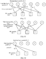
- two symbols of a data layer 2 are mapped to a second and a fourth REs
- a data layer 3 is mapped to the first and the second REs
- a data layer 4 is mapped to the third and the fourth REs
- a data layer 5 is mapped to the first and the fourth REs
- a data layer 6 is mapped to the second and the third REs.
- the network device After determining all these parameters and spreading methods and completing modulation of each layer of data based on the basic modulation scheme of each layer of data, the network device enters the preprocessing operation.
- the preprocessing operation includes three parts, namely, power allocation, angle rotation, and spreading and superposition.
- a mapping manner of the preprocessing operation may be obtained based on Table 1.
- implementation may be performed in the following manner.
- Embodiment 1 provides a procedure instance of downlink modulation and a preprocessing operation of regular spreading. In contrast, this embodiment provides a procedure instance of downlink modulation and a preprocessing operation of irregular spreading.
- control information that needs to be determined includes: a supported terminal, a data layer number (including a layer quantity G k ) occupied by each terminal, a basic modulation scheme corresponding to each layer of data, a quantity Q of REs for spreading, and a preprocessing operation mode.
- information other than information about the terminal supported by the network device may either be determined by the network device and then notified by using signaling, or separately stored by the network device and each terminal through agreement in advance.
- d 1 3 symbols corresponding to the data layer 1 (namely, a terminal 1) are mapped to a first, a second, and a third REs (because all the three REs are occupied, this is no longer sparse spreading actually), two symbols of a data layer 2 are mapped to the first and the second REs, a data layer 3 is mapped to the second and the third REs, a data layer 4 is mapped to the first RE, and a data layer 5 is mapped to the third RE.
- FIG. 7 it can be further learned from FIG. 7 that in this embodiment, whether different data layers belong to a same terminal does not affect subsequent processing.
- the network device After determining all these parameters and spreading methods and completing modulation of each layer of data based on the basic modulation scheme of each layer of data, the network device enters the preprocessing operation.
- the preprocessing operation includes three parts, namely, power allocation, angle rotation, and spreading and superposition.
- a mapping manner of the preprocessing operation may be obtained based on Table 2.
- implementation may be performed in the following manner.
- This embodiment provides another downlink preprocessing operation method.
- a network device schedules N terminals.
- the J layers of data may multiplex completely same REs by using a superposition modulation scheme and a same spreading method. Data layers in a same group do not belong to a same terminal.
- quantities of layers in the groups may be different (a specific value of J and a power difference between the J layers of data are determined based on a specific superposition modulation scheme, and this is not limited herein).
- data of each group of terminals is spread, in a manner similar to that in CDMA, to the Q REs for transmission.
- control information that needs to be determined includes: a supported terminal, a data layer number (including a layer quantity G k ) occupied by each terminal, a basic modulation scheme corresponding to each layer of data, a quantity Q of REs for spreading, and a preprocessing operation mode.
- information about a spreading coefficient also needs to be determined. If there are a plurality of groups of spreading coefficients, group numbers of the spreading coefficients further need to be learned of.
- information other than information about the terminal supported by the network device may either be determined by the network device and then notified by using signaling, or separately stored by the network device and each terminal through agreement in advance.
- Table 3 These parameters are determined by the network device and notified to each terminal.
- the notified content further includes a number of a layer at which the data of each terminal is located. Compared with Table 1, in Table 3, only distribution of basic modulation symbol quantities of the data layers is changed and a spreading factor is added. A value of the spreading factor indicates a quantity of REs to which each basic modulation symbol is spread. Mapping of each layer of data to the REs may be obtained based on Table 3. For this, refer to FIG.
- Embodiment 1 to Embodiment 3 discuss a case of downlink transmission.
- this embodiment, Embodiment 5, and Embodiment 6 discuss how to perform data modulation and a preprocessing operation in uplink transmission.
- this embodiment provides a procedure of generating an uplink transmission symbol S used by a terminal to perform regular spreading based on scheduling by a network device.
- control information that needs to be determined includes: a data layer number (including a layer quantity G k ) occupied by a k th terminal, a basic modulation scheme corresponding to each layer of data, a quantity Q of REs for spreading, and a preprocessing operation mode.
- the control information may either be determined by the network device and then notified to the terminal by using signaling, or separately stored by the network device and the terminal through agreement in advance.
- the network device and the terminal may agree in advance on the data layer quantity G k and the basic modulation scheme.
- the specific quantity Q of REs and preprocessing operation mode are notified by the network device to the terminal by using signaling.
- control information corresponding to all terminals participating in non-orthogonal transmission on the Q REs is stored.
- each layer of data may occupy a different RE. Steps of power allocation and angle rotation in the preprocessing operation may be omitted (in terms of a form, matrixes F 2 and F 3 are identity matrixes, or inputs of functions F 2 ( ⁇ ) and F 3 ( ⁇ ) are equal to outputs).
- FIG. 9 For spreading mapping corresponding to each layer of data in Table 4, refer to FIG. 9 .
- Two symbols corresponding to a data layer 1 are mapped to a first and a third REs.
- Two symbols of a data layer 2 are mapped to a second and a fourth REs.
- a data layer 3 is mapped to the first and the second REs.
- a data layer 4 is mapped to the third and the fourth REs.
- a data layer 5 is mapped to the first and the fourth REs.
- a data layer 6 is mapped to the second and the third REs. It can be learned that, this is completely the same as FIG. 6 .
- each terminal may reserve only X in Embodiment 1, data in F 1 , F 2 , and F 3 that corresponds to the terminal, and a preprocessing operation matrix or function.
- the network device receives data that is sent by each terminal after the preprocessing operation. Therefore, the preprocessing operation matrix and function obtained through combination by N terminals are both consistent with those in Embodiment 1. Details are not described herein again.
- Each terminal proactively performs operations based on FIG. 5 after determining, based on scheduling information of the network device, a number of a data layer occupied by each terminal.
- Table 4 Parameter table of an uplink regular spreading embodiment Parameter Value Total data layer quantity G 6 Distribution of basic modulation symbol quantities of data layers [2,2,2,2,2,2] Quantity Q of REs 4 Overload probability (G/Q) 150% Mode Uplink
- the network device may work out a basic modulation symbol of each terminal based on preset precoding matrix information or function information. Then an encoded information bit can be restored based on a basic modulation constellation diagram and is further decoded.
- this embodiment provides a procedure of generating an uplink to-be-transmitted symbol S used by a terminal to perform irregular spreading based on scheduling by a network device.
- control information that needs to be determined includes: a data layer number (including a layer quantity G k ) occupied by a k th terminal, a basic modulation scheme corresponding to each layer of data, a quantity Q of REs for spreading, and a preprocessing operation mode.
- the control information may either be determined by the network device and then notified to the terminal by using signaling, or separately stored by the network device and the terminal through agreement in advance.
- each terminal may reserve only X in Embodiment 2, data in F 1 , F 2 , and F 3 that corresponds to the terminal, and a preprocessing operation matrix or function.
- the network device receives data that is sent by each terminal after the preprocessing operation. Therefore, the preprocessing operation matrix and function obtained through combination by N terminals are both consistent with those in Embodiment 2. Details are not described herein again.
- Each terminal proactively performs operations based on FIG. 5 after determining, based on scheduling information of the network device, a number of a data layer occupied by each terminal.
- Table 5 Parameter table of an uplink irregular spreading embodiment Parameter Value Total data layer quantity G 5 Distribution of basic modulation symbol quantities of data layers [3,2,2,1,1] Quantity Q of REs 3 Overload probability (G/Q) 166.7% Mode Uplink
- the spreading herein is irregular, and symbol quantities of the layers may not be consistent. In other words, different layers occupy different quantities of REs. Therefore, the spreading herein is referred to as irregular spreading. However, once a mapping manner is determined, procedures of the preprocessing operation are consistent.
- a terminal uses, based on a scheduling result of the network device, the data layers 2 and 3 for uplink transmission. Therefore, based on FIG. 13 , basic modulation symbols corresponding to the data layers are to be sent on the first, the second, and the third REs.
- single-terminal transmission is described herein, other layers of terminals actually also multiplex these RE resources in this case, to reach a higher overload probability.
- the network device may work out a basic modulation symbol of each terminal based on preset precoding matrix information or function information. Then an encoded information bit can be restored based on a basic modulation constellation diagram and is further decoded.
- this embodiment provides a procedure of generating an uplink to-be-transmitted symbol by a terminal based on scheduling by a network device. Similarly, the network device schedules N terminals.
- the J layers of data may multiplex completely same REs by using a superposition modulation scheme. Data layers in a same group do not belong to a same terminal. Certainly, quantities of data layers in the groups may be different. Before the terminal performs modulation and a preprocessing operation shown in FIG.
- control information that needs to be determined includes: a data layer number (including a layer quantity G k ) occupied by a k th terminal, a basic modulation scheme corresponding to each layer of data, a quantity Q of REs for spreading, and a preprocessing operation mode.
- information about a spreading coefficient also needs to be determined. If there are a plurality of groups of spreading coefficients, group numbers of the spreading coefficients further need to be learned of.
- the control information may either be determined by the network device and then notified to the terminal by using signaling, or separately stored by the network device and the terminal through agreement in advance.
- symbols of the terminals are extended by using a complex sequence with a low correlation, and then are sent on a same time-frequency resource.
- Embodiment 3 an example provided in Embodiment 3 is used herein.
- Table 6 These parameters are all determined by the network device and notified to each terminal.
- the notified content further includes a number of a layer at which the data of each terminal is located. Compared with Table 4, in Table 6, only distribution of basic modulation symbol quantities of the data layers is changed.
- each terminal may reserve only X in Embodiment 3, data in F 1 , F 2 , and F 3 that corresponds to the terminal, and a preprocessing operation matrix or function.
- the network device receives data that is sent by each terminal after the preprocessing operation. Therefore, the preprocessing operation matrix and function obtained through combination by N terminals are both consistent with those in Embodiment 3. Details are not described herein again.
- a specific quantity of layers of data occupied by each terminal is not limited herein, provided that layers of data in a same group belong to different terminals.
- Each terminal proactively performs operations based on FIG. 5 after determining, based on scheduling information of the network device, a number of a data layer occupied by each terminal.
- there are also two preprocessing operation methods. Cases in which a same terminal occupies one layer (a single layer) of data and a plurality of layers of data are separately discussed below by using examples.
- Table 6 Uplink spreading parameter table Parameter Value Total data layer quantity G 6 Distribution of basic modulation symbol quantities of data layers [1,1,1,1,1] Quantity Q of REs 4 Overload probability (G/Q) 150% Mode Uplink
- a sequence length is Q
- a terminal 1 uses, based on a scheduling result of the network device, a data layer 1 for uplink transmission.
- F 2 and F 3 are identity matrixes. Certainly, alternatively, F 2 and F 3 may not be set as identity matrixes.
- a sequence length is Q
- F 2 and F 3 are identity matrixes.
- F 2 may not be considered. This is because in downlink transmission, it is started from a same network device, and terminals in a same group need to be distinguished based on power. In this case, power control needs to be considered. However, in uplink transmission, power of terminals scheduled to a same group to the network device has been naturally adjusted because of different paths. Therefore, power adjustment may not be performed herein. It should be noted that, although single-terminal transmission is described herein, other layers of terminals actually also multiplex these RE resources in this case, to reach a higher overload probability.
- F 1 herein is a column orthogonal matrix. In other words, columns are orthogonal to each other, and this is orthogonal spreading. However, this does not need to be limited between different terminals.
- the network device may work out a basic modulation symbol of each terminal based on preset precoding matrix information or function information of each terminal. Then an encoded information bit can be restored based on a basic modulation constellation diagram and is further decoded.
- FIG. 19 is a schematic structural diagram of a network device.
- a network device 11 includes a modulation module 100, a combination module 110, a preprocessing operation module 150, and a processing module 160.
- the modulation module 100 is coupled to the combination module 110.
- the processing module 160 is coupled to the modulation module 100 and the preprocessing operation module 150.
- the processing module 160 is configured to divide data of any one of N terminals scheduled on Q resource elements into G k layers of data.
- the processing module processes a maximum of G layers of data on the Q resource elements.
- G k is a positive integer
- Q is a positive integer
- Q ⁇ G is a positive integer
- N is a positive integer
- N ⁇ G is a positive integer
- the modulation module 100 is configured to perform basic modulation on the G k layers of data to obtain D k basic modulation symbols, where D k ⁇ G k , and D k is a positive integer.
- the combination module 110 is configured to combine the basic modulation symbols that are of the N terminals and that are obtained after the basic modulation to obtain a combined symbol vector X.
- the preprocessing operation module 150 is configured to map the symbol vector X to the Q resource elements to obtain a data vector S.
- a symbol quantity of the symbol vector X is greater than a symbol quantity of the data vector S.
- the symbol quantity of the data vector S is the quantity Q of the resource elements.
- That the preprocessing operation module 150 is configured to map the symbol vector X to the Q resource elements to obtain a data vector S includes: the preprocessing operation module 150 is configured to map the symbol vector X to the Q resource elements by using a preprocessing operation to obtain the data vector S.
- the preprocessing operation includes at least spreading and superposition.
- the preprocessing operation module 150 includes a power adjustment module 120, an angle rotation module 130, and a spreading and superposition module 140.
- the power adjustment module 120 is configured to adjust power of the basic modulation symbol.
- the angle rotation module 130 is configured to rotate an angle of the basic modulation symbol.
- the spreading and superposition module 140 is configured to perform spreading and superposition on the basic modulation symbol.
- the power adjustment module 120 and the angle rotation module 130 may change an order of sequential processing.
- the power adjustment module 120, the angle rotation module 130, and the spreading and superposition module 140 may further jointly form the preprocessing operation module 150.
- the power adjustment module 120 and the angle rotation module 130 may further be combined into a power adjustment and angle rotation module 170.
- the power adjustment and angle rotation module 170 is configured to perform power adjustment and angle rotation on the basic modulation symbol at the same time.
- a power adjustment matrix F 2 is an identity matrix or when a power adjustment function F 2 (X) is equal to X
- the power adjustment module 120 may not be used.
- an angle rotation matrix F 3 is an identity matrix or when an angle rotation function F 3 (X) is equal to X
- the angle rotation module 130 may not be used.
- the modulation module 100 is coupled to the combination module 110.
- the combination module 110 is coupled to the preprocessing operation module 150.
- the modulation module 100 modulates a plurality of layers of data from the N terminals into basic modulation symbols based on a basic modulation scheme of each layer.
- the combination module 110 sequentially combines the data into the vector X based on a basic modulation symbol combination method according to any one of Embodiment 1 to Embodiment 3.
- the vector X is input into the preprocessing operation module 150.
- the preprocessing operation module 150 processes the vector X by using a preprocessing operation method according to any one of Embodiment 1 to Embodiment 3, maps the vector X to Q REs, and outputs the vector S.
- the processing module 160 is further configured to perform further processing on the vector S. Such processing includes but is not limited to an IFFT transform.
- the modulation module 100, the combination module 110, the preprocessing operation module 150, and the processing module 160 may further be integrated into one processor.
- the processor is configured to process the data of the N terminals.
- FIG. 20 is a schematic structural diagram of a terminal. Compared with FIG. 19 , a difference is that FIG. 19 is a schematic structural diagram of a network device while FIG. 20 is a schematic structural diagram of a terminal 12.
- an output of a combination module 210 is X k
- an output of a preprocessing operation module 250 is S k .
- this embodiment relates to only one terminal while FIG. 19 relates to one or more terminals.
- the terminal 12 is one of N terminals scheduled by a network device 11 on Q resource elements.
- the network device 11 receives a maximum of G layers of data on the Q resource elements.
- the terminal 12 includes a modulation module 200, a combination module 210, a preprocessing operation module 250, and a processing module 260.
- the modulation module 200 is coupled to the combination module 210
- the combination module 210 is coupled to the modulation module 200 and the preprocessing operation module 250
- the processing module 260 is coupled to the modulation module 200 and the preprocessing operation module 250.
- the processing module 260 is configured to divide data sent on the Q resource elements into G k layers of data.
- G k is a positive integer
- Q is a positive integer
- Q ⁇ G is a positive integer
- N is a positive integer
- N ⁇ G is a positive integer
- the modulation module 200 is configured to perform basic modulation on the G k layers of data to obtain D k basic modulation symbols, where D k ⁇ G k , and D k is a positive integer.
- the combination module 210 is configured to combine the D k basic modulation symbols to obtain a combined symbol vector X k .
- the preprocessing operation module 250 is configured to map the symbol vector X k to the Q resource elements to obtain a data vector S k , where a sum of symbol quantities of symbol vectors of the N terminals is greater than Q.
- the preprocessing operation module 250 is configured to perform a preprocessing operation on the symbol vector X k includes: the preprocessing operation module 250 is configured to map the symbol vector X k to the Q resource elements by using the preprocessing operation to obtain the data vector S k , where the preprocessing operation includes at least spreading and superposition.
- the preprocessing operation module 250 includes a power adjustment module 220, an angle rotation module 230, and a spreading and superposition module 240.
- the power adjustment module 220 is configured to adjust power of the basic modulation symbol.
- the angle rotation module 230 is configured to rotate an angle of the basic modulation symbol.
- the spreading and superposition module 240 is configured to perform spreading and superposition on the basic modulation symbol.
- the power adjustment module 220 and the angle rotation module 230 may change an order of sequential processing.
- the power adjustment module 220, the angle rotation module 230, and the spreading and superposition module 240 may further jointly form the preprocessing operation module 250.
- the power adjustment module 220 and the angle rotation module 230 may further be combined into a power adjustment and angle rotation module 270.
- the power adjustment and angle rotation module 270 is configured to perform power adjustment and angle rotation on the basic modulation symbol at the same time.
- a power adjustment matrix F 2 is an identity matrix or when a power adjustment function F 2 (X) is equal to X
- the power adjustment module 220 may not be used.
- an angle rotation matrix F 3 is an identity matrix or when an angle rotation function F 3 (X) is equal to X
- the angle rotation module 230 may not be used.
- the modulation module 200 modulates at least one layer of data of the terminal into basic modulation symbols based on a basic modulation scheme of each layer.
- the G k layers of data of the terminal are sequentially combined into the vector X k by using a basic modulation symbol combination method according to any one of Embodiment 4 to Embodiment 6.
- the vector X k is input into the preprocessing operation module 250.
- the preprocessing operation module 250 processes the vector X k by using a preprocessing operation method according to any one of Embodiment 4 to Embodiment 6, and outputs the vector S k , for further processing in the processing module 260.
- Such processing includes but is not limited to an IFFT transform.
- the modulation module 200, the combination module 210, the preprocessing operation module 250, and the processing module 260 may further be integrated into one processor.
- the processor is configured to process the data of the terminal.
- the disclosed apparatus and method may be implemented in other manners.
- the described apparatus embodiments are merely examples.
- the module or device division is merely logical function division and may be other division in actual implementation.
- a plurality of modules or devices may be combined to form a new device.
- the displayed or discussed mutual couplings or direct couplings or communication connections may be implemented by using some interfaces.
- the indirect couplings or communication connections between the apparatuses, devices, or units may be implemented in electronic, mechanical, or other forms.
- the devices in the embodiments of this application are physical units, and some functions of the devices may be implemented by software or by hardware. A person skilled in the art may select a corresponding implementation based on actual needs.
- the processor of the present invention may be a general purpose processor, an integrated circuit, or a chip.
- modules in the embodiments of this application may be integrated into one processor, or each of the modules may exist alone physically, or two or more modules may be integrated into one unit.
Landscapes
- Engineering & Computer Science (AREA)
- Signal Processing (AREA)
- Computer Networks & Wireless Communication (AREA)
- Quality & Reliability (AREA)
- Digital Transmission Methods That Use Modulated Carrier Waves (AREA)
- Mobile Radio Communication Systems (AREA)
Claims (11)
- Datenverarbeitungsverfahren, umfassend:Teilen, durch ein Endgerät, von Daten, die von dem Endgerät auf Q Ressourcenelementen gesendet werden, in Gk Datenschichten, wobei das Endgerät eines aus einer Vielzahl von Endgeräten ist, die von einer Netzwerkvorrichtung auf den Q Ressourcenelementen geplant werden, wobei die Netzwerkvorrichtung ein Maximum von G Datenschichten auf den Q Ressourcenelementen von der Vielzahl von Endgeräten empfängt, wobei Gk eine positive ganze Zahl ist, Gk < G ist, Q eine positive ganze Zahl ist und Q < G ist;Ausführen (401), durch das Endgerät, einer Basismodulation auf jeder der Gk Datenschichten, um Dk Basismodulationssymbole zu erhalten, wobei Dk ≥ Gk ist, und Dk eine positive ganze Zahl ist;Kombinieren (410), durch das Endgerät, der Dk Basismodulationssymbole, um einen kombinierten Symbolvektor Xk zu erhalten; undZuordnen (450), durch das Endgerät, des Symbolvektors Xk zu den Q Ressourcenelementen, um einen Datenvektor Sk zu erhalten, wobei das Zuordnen, durch das Endgerät, des Symbolvektors Xk zu den Q Ressourcenelementen, um einen Datenvektor Sk zu erhalten, folgendes aufweist: Zuordnen, durch das Endgerät, des Symbolvektors Xk zu den Q Ressourcenelementen, indem eine Vorverarbeitungsoperation verwendet wird, um einen Datenvektor Sk zu erhalten, wobei die Vorverarbeitungsoperation mindestens eine Streuung und Überlagerung umfasst, wobei das Verfahren dadurch gekennzeichnet ist, dass die Vorverarbeitungsoperation aufweist:zuerst Ausführen einer Leistungsanpassung (420), danach Ausführen einer Winkeldrehung (430) und danach Ausführen einer Streuung und Überlagerung (440); oderzuerst Ausführen einer Winkel drehung (430), danach Ausführen einer Leistungsanpassung (420) und danach Ausführen einer Streuung und Überlagerung (440); oderzuerst gleichzeitiges Ausführen einer Leistungsanpassung und einer Winkeldrehung (420, 430) und danach Ausführen einer Streuung und Überlagerung (440); oder gleichzeitiges Ausführen einer Leistungsanpassung, einer Winkeldrehung und einer Streuung und Überlagerung (420, 430, 440),und dadurch, dassin der Basismodulation jede Schicht ein anderes Konstellationsdiagramm aufweist und eine unterschiedliche Anzahl von Symbolen ausgibt.
- Verfahren nach einem von Anspruch 1, wobei das Zuordnen, durch das Endgerät, des Symbolvektors Xk zu den Q Ressourcenelementen, um einen Datenvektor Sk zu erhalten, folgendes aufweist:Sk = F1F2F3 Xk, Sk = F1F3F2 Xk, Sk = F1F23 Xk, Sk = F1F32 Xk oder Sk = FXk, wobei F23 = F2F3, F32 = F3F2, F = F1F2F3 oder F = F1F3F2 ist; undF1 eine nicht-orthogonale Streuungs- und Überlagerungsmatrix ist, F2 eine Winkeldrehungsmatrix ist und F3 eine Leistungszuteilungsmatrix F3 ist.
- Verfahren nach Anspruch 2, wobei mindestens eine von F2 oder F3 eine Einheitsmatrix ist.
- Verfahren nach Anspruch 1, wobei das Zuordnen, durch das Endgerät, des Symbolvektors Xk zu den Q Ressourcenelementen, um einen Datenvektor Sk zu erhalten, folgendes aufweist:
Sk = F1(F2(F3(Xk))), Sk = F1(F3(F2(Xk))), Sk = F1(F23(Xk)), Sk = F1(F32(Xk)) oder Sk = F(Xk), wobei F23(·) = F3(F2(·)), F32(·) = F2(F3(·)), F = F1(F2(F3(·))) oder F = F1(F3(F2(·))), wobei F1(·) eine nicht-orthogonale Streuungs- und Überlagerungsfunktion ist, F2(·) eine Winkeldrehungsfunktion ist und F3(·) eine Leistungszuteilungsfunktion ist. - Verfahren nach Anspruch 4, wobei mindestens eine Funktion von F2(·) und F3(·) einen Ausgang aufweist, der gleich einem Eingang ist.
- Verfahren nach Anspruch 1, wobei das Verfahren außerdem umfasst: dass die Gk Datenschichten mindestens zwei Basismodulationsschemen entsprechen.
- Endgerät (12), wobei das Endgerät eines Aus einer Vielzahl von Endgeräten ist, die von einer Netzwerkvorrichtung auf Q Ressourcenelemente geplant werden, wobei die Netzwerkvorrichtung ein Maximum von G Datenschichten auf den Q Ressourcenelementen von der Vielzahl von Endgeräten empfängt und wobei das Endgerät (12) ein Modulationsmodul (200), ein Kombinationsmodul (210), ein Vorverarbeitungsoperationsmodul (250) und ein Verarbeitungsmodul (260) umfasst, wobei das Modulationsmodul (200) mit dem Kombinationsmodul (210) verbunden ist, wobei das Kombinationsmodul (210) mit dem Modulationsmodul (200) und dem Vorverarbeitungsoperationsmodul (250) verbunden ist, und wobei das Verarbeitungsmodul (260) mit dem Modulationsmodul (200) und dem Vorverarbeitungsoperationsmodul (250) verbunden ist;
wobei das Verarbeitungsmodul (260) konfiguriert ist zum Teilen von Daten, die von dem Endgerät auf den Q Ressourcenelementen gesendet werden, in Gk Datenschichten, wobei Gk eine positive ganze Zahl ist, Gk < G ist, Q eine positive ganze Zahl ist und Q < G ist;
wobei das Modulationsmodul (200) konfiguriert ist zum Ausführen einer Basismodulation auf jeder der Gk Datenschichten, um Dk Basismodulationssymbole zu erhalten, wobei Dk ≥ Gk ist, und Dk eine positive ganze Zahl ist;
wobei das Kombinationsmodul (210) konfiguriert ist zum Kombinieren der Dk Basismodulationssymbole, um einen kombinierten Symbolvektor Xk zu erhalten; und wobei das Vorverarbeitungsoperationsmodul (250) konfiguriert ist zum Zuordnen des Symbolvektors Xk zu den Q Ressourcenelementen, um einen Datenvektor Sk zu erhalten, wobei das Konfigurieren des Vorverarbeitungsoperationsmoduls (250) zum Ausführen einer Vorverarbeitungsoperation an dem Symbolvektor Xk umfasst, dass:das Vorverarbeitungsoperationsmodul (250) konfiguriert ist zum Zuordnen des Symbolvektors Xk zu den Q Ressourcenelementen, indem die Vorverarbeitungsoperation verwendet wird, um einen Datenvektor Sk zu erhalten, wobei die Vorverarbeitungsoperation mindestens eine Streuung und Überlagerung umfasst,wobei das Endgerät dadurch gekennzeichnet ist, dass:
das Vorverarbeitungsoperationsmodul (250) die folgenden Module umfasst: ein Leistungsanpassungsmodul (220), ein Winkeldrehungsmodul (230) und ein Streuungs- und Überlagerungsmodul (240), wobei das Leistungsanpassungsmodul (220) konfiguriert ist zum Anpassen der Leistung des Basismodulationssymbols, das Winkeldrehungsmodul (230) konfiguriert ist zum Drehen eines Winkels des Basismodulationssymbols, und das Streuungs- und Überlagerungsmodul (240) konfiguriert ist zum Ausführen einer Streuung und Überlagerung an dem Basismodulationssymbol, wobei:das Leistungsanpassungsmodul (220) mit dem Kombinationsmodul (210) und dem Winkeldrehungsmodul (230) verbunden ist, und das Winkeldrehungsmodul (230) mit dem Leistungsanpassungsmodul (220) und dem Streuungs- und Überlagerungsmodul (240) verbunden ist; oder das Winkeldrehungsmodul (230) mit dem Kombinationsmodul (210) und dem Leistungsanpassungsmodul (220) verbunden ist, und das Leistungsanpassungsmodul (220) mit dem Streuungs- und Überlagerungsmodul (240) und dem Winkeldrehungsmodul (230) verbunden ist, und dadurch, dassin der Basismodulation jede Schicht ein anderes Konstellationsdiagramm aufweist und eine unterschiedliche Anzahl von Symbolen ausgibt. - Endgerät nach Anspruch 7, wobei die Vorverarbeitungsoperation aufweist:Sk = F1F2F3 Xk, Sk = F1F3F2 Xk, Sk = F1F23 Xk, Sk = F1F32 Xk oder Sk = FXk, wobei F23 = F2F3, F32 = F3F2, F = F1F2F3 oder F = F1F3F2 ist; undF1 eine nicht-orthogonale Streuungs- und Überlagerungsmatrix ist, F2 eine Winkeldrehungsmatrix ist und F3 eine Leistungszuteilungsmatrix F3 ist.
- Endgerät nach Anspruch 8, wobei mindestens eine von F2 oder F3 eine Einheitsmatrix ist.
- Endgerät nach Anspruch 7, wobei die Vorverarbeitungsoperation aufweist:
Sk = F1(F2(F3(Xk))), Sk = F1(F3(F2(Xk))), Sk = F1(F23(Xk)), Sk = F1(F32(Xk)) oder Sk = F(Xk), wobei F23(·) = F3(F2(·)), F32(·) = F2(F3(·)), F = F1(F2(F3(·))) oder F = F1(F3(F2(·))), wobei F1(·) eine nicht-orthogonale Streuungs- und Überlagerungsfunktion ist, F2(·) eine Winkeldrehungsfunktion ist und F3(·) eine Leistungszuteilungsfunktion ist. - Endgerät nach Anspruch 10, wobei mindestens eine Funktion von F2(·) and F3(·) einen Ausgang aufweist, der gleich einem Eingang ist.
Applications Claiming Priority (2)
| Application Number | Priority Date | Filing Date | Title |
|---|---|---|---|
| CN201610425145.5A CN107508661B (zh) | 2016-06-14 | 2016-06-14 | 一种数据处理的方法、网络设备和终端 |
| PCT/CN2017/083589 WO2017215367A1 (zh) | 2016-06-14 | 2017-05-09 | 一种数据处理的方法、网络设备和终端 |
Publications (3)
| Publication Number | Publication Date |
|---|---|
| EP3461049A1 EP3461049A1 (de) | 2019-03-27 |
| EP3461049A4 EP3461049A4 (de) | 2019-06-12 |
| EP3461049B1 true EP3461049B1 (de) | 2020-07-08 |
Family
ID=60663463
Family Applications (1)
| Application Number | Title | Priority Date | Filing Date |
|---|---|---|---|
| EP17812479.8A Active EP3461049B1 (de) | 2016-06-14 | 2017-05-09 | Verfahren und entsprechendes endgerät zur datenverarbeitung |
Country Status (4)
| Country | Link |
|---|---|
| US (1) | US10790926B2 (de) |
| EP (1) | EP3461049B1 (de) |
| CN (1) | CN107508661B (de) |
| WO (1) | WO2017215367A1 (de) |
Families Citing this family (11)
| Publication number | Priority date | Publication date | Assignee | Title |
|---|---|---|---|---|
| CN110138702B (zh) * | 2018-02-08 | 2021-03-05 | 中国移动通信有限公司研究院 | 一种数据传输的方法和设备 |
| US11424799B2 (en) | 2018-06-12 | 2022-08-23 | Google Llc | Beamforming-based grant-free non-orthogonal multiple access transmission |
| CN112005515B (zh) | 2018-06-15 | 2023-03-24 | 谷歌有限责任公司 | 用于无线网络的基于cbg的noma传输 |
| CN112313900A (zh) | 2018-06-22 | 2021-02-02 | 谷歌有限责任公司 | 多分支noma无线通信 |
| CN112514517B (zh) | 2018-08-10 | 2024-06-04 | 谷歌有限责任公司 | 用于noma异步传输中的上行链路控制信道的方法和装置 |
| WO2020069090A1 (en) * | 2018-09-26 | 2020-04-02 | Google Llc | Non-orthogonal multiple access configuration in split base station architectures |
| CN112956132B (zh) | 2018-11-09 | 2022-10-21 | 中兴通讯股份有限公司 | 基于符号组的扩展方案的设计 |
| CN111200571B (zh) * | 2018-11-19 | 2021-10-01 | 华为技术有限公司 | 一种信号传输方法及装置 |
| CN111464207B (zh) * | 2019-01-18 | 2021-04-02 | 电信科学技术研究院有限公司 | 一种noma多层传输方法及其装置 |
| CN112019298B (zh) * | 2019-05-31 | 2021-11-19 | 华为技术有限公司 | 编码调制方法、解调译码方法、装置及设备 |
| CN112565153B (zh) * | 2020-11-30 | 2023-06-09 | 沈阳理工大学 | 基于旋转映射的scma多用户码本设计方法 |
Family Cites Families (17)
| Publication number | Priority date | Publication date | Assignee | Title |
|---|---|---|---|---|
| US7298805B2 (en) * | 2003-11-21 | 2007-11-20 | Qualcomm Incorporated | Multi-antenna transmission for spatial division multiple access |
| US8204149B2 (en) * | 2003-12-17 | 2012-06-19 | Qualcomm Incorporated | Spatial spreading in a multi-antenna communication system |
| CN101232484B (zh) * | 2007-01-26 | 2011-08-17 | 电信科学技术研究院 | 信号传输方法、装置及通信系统 |
| ES2402053T3 (es) | 2007-09-06 | 2013-04-26 | Lg Electronics Inc. | Método y sistema para la transmisión y recepción de señales |
| DE602008000755D1 (de) * | 2008-01-11 | 2010-04-15 | Ntt Docomo Inc | Verfahren, Vorrichtung und System zur Kanalschätzung in Zwei-Wege-Relais-Netzwerken |
| CN102857284B (zh) * | 2011-06-28 | 2015-12-09 | 上海华为技术有限公司 | 数据发射方法、接收方法、装置及系统 |
| EP2835926B1 (de) * | 2013-08-05 | 2019-06-12 | Alcatel Lucent | Sendevorrichtung zur Konditionierung eines Mehrträgersignals, Netzwerkknoten, Verfahren zur Konditionierung eines Mehrträgersignals und Computerprogramm dafür |
| EP2840749B1 (de) * | 2013-08-23 | 2020-09-30 | Alcatel Lucent | Empfänger und empfangsverfahren für ein filtriertes mehrträgersignal |
| CN104796243B (zh) | 2014-01-22 | 2018-05-29 | 电信科学技术研究院 | 一种数据传输、数据接收检测方法及基站、用户设备 |
| CN104868983B (zh) | 2014-02-26 | 2018-03-27 | 电信科学技术研究院 | 一种数据传输、数据接收检测方法及基站、用户设备 |
| EP3001623B1 (de) * | 2014-09-29 | 2017-06-21 | Alcatel Lucent | Wahl der seitenbandunterdrückung des filters in abhängigkeit der kanalqualität in universal filtered multicarrier |
| CN105634702B (zh) * | 2014-12-01 | 2019-09-10 | 中兴通讯股份有限公司 | 多用户信息共道发送、接收方法及其装置 |
| CN105991257B (zh) * | 2015-01-23 | 2020-10-23 | 北京三星通信技术研究有限公司 | 基于滤波器组的信号生成、发送和接收方法及其装置 |
| US20180063819A1 (en) * | 2015-03-31 | 2018-03-01 | Ntt Docomo, Inc. | Radio base station, user terminal and radio communication method |
| US20160309542A1 (en) * | 2015-04-16 | 2016-10-20 | Sharp Laboratories Of America, Inc. | Systems and methods for constellation superposition |
| WO2016182922A1 (en) * | 2015-05-08 | 2016-11-17 | Interdigital Patent Holdings, Inc. | Cyclic prefix-aligned generalized and n-continuous orthogonal frequency division multiplexing |
| JP6694075B2 (ja) * | 2016-03-30 | 2020-05-13 | アイディーエーシー ホールディングス インコーポレイテッド | ユニークワード(UW)離散フーリエ変換拡散直交周波数分割多重(DFT−s−OFDM)を用いて物理レイヤ効率を改善するための方法および手順 |
-
2016
- 2016-06-14 CN CN201610425145.5A patent/CN107508661B/zh active Active
-
2017
- 2017-05-09 WO PCT/CN2017/083589 patent/WO2017215367A1/zh not_active Ceased
- 2017-05-09 EP EP17812479.8A patent/EP3461049B1/de active Active
-
2018
- 2018-12-13 US US16/219,088 patent/US10790926B2/en active Active
Non-Patent Citations (1)
| Title |
|---|
| None * |
Also Published As
| Publication number | Publication date |
|---|---|
| EP3461049A4 (de) | 2019-06-12 |
| CN107508661B (zh) | 2020-07-21 |
| EP3461049A1 (de) | 2019-03-27 |
| CN107508661A (zh) | 2017-12-22 |
| US20190132076A1 (en) | 2019-05-02 |
| US10790926B2 (en) | 2020-09-29 |
| WO2017215367A1 (zh) | 2017-12-21 |
Similar Documents
| Publication | Publication Date | Title |
|---|---|---|
| EP3461049B1 (de) | Verfahren und entsprechendes endgerät zur datenverarbeitung | |
| CN114503449B (zh) | 用于复用部分信道状态信息的方法和装置 | |
| CN105900387B (zh) | 一种资源分配方法及装置 | |
| CN103929292B (zh) | 通信装置及通信方法 | |
| CN102014475B (zh) | 资源映射、码分复用方法及装置 | |
| CN106452697B (zh) | 一种上行数据的发送方法、接收方法及装置 | |
| CA2698237C (en) | Systems and methods for designing a reference signal to be transmitted in a multiplexed cellular system | |
| RU2560718C1 (ru) | Устройство генерирования кодов, устройство генерирования опорных сигналов и соответствующие способы | |
| CN102299769A (zh) | 一种下行控制信息传输方法及装置 | |
| WO2017107707A1 (zh) | 一种确定多用户传输方式的方法及装置 | |
| Yan et al. | Non-orthogonal multiple access schemes for 5G | |
| JP6419943B2 (ja) | 非対称なチャネル次元を有するネットワークにおける干渉アライメント | |
| WO2018228460A1 (zh) | 相位跟踪参考信号处理方法与装置 | |
| KR102286877B1 (ko) | 필터뱅크 기반의 멀티 캐리어 신호 송수신을 위한 필터 재사용 방법 | |
| WO2017002013A1 (en) | Apparatus and method for reusing existing constellation for superposed transmission | |
| CN116436579A (zh) | 一种通信方法、装置及设备 | |
| EP4589855A1 (de) | Kommunikationsverfahren und -vorrichtung sowie speichermedium | |
| EP3017640A1 (de) | System und verfahren für kooperative vorcodierung in zweischichtigen heterogenen drahtlosen netzwerken | |
| CN107547186B (zh) | 基于能效函数来确定多址接入技术进行无线通信的方法 | |
| EP4289099B1 (de) | Verfahren und vorrichtung zum senden und empfangen von signalen | |
| Velimirovic et al. | Algebraically constructed short sequence families for 5G NOMA techniques | |
| WO2024208330A1 (zh) | 一种通信方法及装置 | |
| CN121772005A (zh) | 通信方法和通信装置 | |
| CN102801513A (zh) | 资源映射、码分复用方法及装置 |
Legal Events
| Date | Code | Title | Description |
|---|---|---|---|
| STAA | Information on the status of an ep patent application or granted ep patent |
Free format text: STATUS: THE INTERNATIONAL PUBLICATION HAS BEEN MADE |
|
| PUAI | Public reference made under article 153(3) epc to a published international application that has entered the european phase |
Free format text: ORIGINAL CODE: 0009012 |
|
| STAA | Information on the status of an ep patent application or granted ep patent |
Free format text: STATUS: REQUEST FOR EXAMINATION WAS MADE |
|
| 17P | Request for examination filed |
Effective date: 20181221 |
|
| AK | Designated contracting states |
Kind code of ref document: A1 Designated state(s): AL AT BE BG CH CY CZ DE DK EE ES FI FR GB GR HR HU IE IS IT LI LT LU LV MC MK MT NL NO PL PT RO RS SE SI SK SM TR |
|
| AX | Request for extension of the european patent |
Extension state: BA ME |
|
| A4 | Supplementary search report drawn up and despatched |
Effective date: 20190515 |
|
| RIC1 | Information provided on ipc code assigned before grant |
Ipc: H04L 5/00 20060101AFI20190509BHEP Ipc: H04L 27/34 20060101ALI20190509BHEP Ipc: H04W 52/32 20090101ALI20190509BHEP Ipc: H04L 1/00 20060101ALI20190509BHEP |
|
| DAV | Request for validation of the european patent (deleted) | ||
| DAX | Request for extension of the european patent (deleted) | ||
| GRAP | Despatch of communication of intention to grant a patent |
Free format text: ORIGINAL CODE: EPIDOSNIGR1 |
|
| STAA | Information on the status of an ep patent application or granted ep patent |
Free format text: STATUS: GRANT OF PATENT IS INTENDED |
|
| INTG | Intention to grant announced |
Effective date: 20200108 |
|
| GRAS | Grant fee paid |
Free format text: ORIGINAL CODE: EPIDOSNIGR3 |
|
| GRAA | (expected) grant |
Free format text: ORIGINAL CODE: 0009210 |
|
| STAA | Information on the status of an ep patent application or granted ep patent |
Free format text: STATUS: THE PATENT HAS BEEN GRANTED |
|
| AK | Designated contracting states |
Kind code of ref document: B1 Designated state(s): AL AT BE BG CH CY CZ DE DK EE ES FI FR GB GR HR HU IE IS IT LI LT LU LV MC MK MT NL NO PL PT RO RS SE SI SK SM TR |
|
| REG | Reference to a national code |
Ref country code: CH Ref legal event code: EP Ref country code: AT Ref legal event code: REF Ref document number: 1289627 Country of ref document: AT Kind code of ref document: T Effective date: 20200715 |
|
| REG | Reference to a national code |
Ref country code: DE Ref legal event code: R096 Ref document number: 602017019584 Country of ref document: DE |
|
| REG | Reference to a national code |
Ref country code: IE Ref legal event code: FG4D |
|
| REG | Reference to a national code |
Ref country code: LT Ref legal event code: MG4D |
|
| REG | Reference to a national code |
Ref country code: AT Ref legal event code: MK05 Ref document number: 1289627 Country of ref document: AT Kind code of ref document: T Effective date: 20200708 |
|
| REG | Reference to a national code |
Ref country code: NL Ref legal event code: MP Effective date: 20200708 |
|
| PG25 | Lapsed in a contracting state [announced via postgrant information from national office to epo] |
Ref country code: ES Free format text: LAPSE BECAUSE OF FAILURE TO SUBMIT A TRANSLATION OF THE DESCRIPTION OR TO PAY THE FEE WITHIN THE PRESCRIBED TIME-LIMIT Effective date: 20200708 Ref country code: LT Free format text: LAPSE BECAUSE OF FAILURE TO SUBMIT A TRANSLATION OF THE DESCRIPTION OR TO PAY THE FEE WITHIN THE PRESCRIBED TIME-LIMIT Effective date: 20200708 Ref country code: AT Free format text: LAPSE BECAUSE OF FAILURE TO SUBMIT A TRANSLATION OF THE DESCRIPTION OR TO PAY THE FEE WITHIN THE PRESCRIBED TIME-LIMIT Effective date: 20200708 Ref country code: PT Free format text: LAPSE BECAUSE OF FAILURE TO SUBMIT A TRANSLATION OF THE DESCRIPTION OR TO PAY THE FEE WITHIN THE PRESCRIBED TIME-LIMIT Effective date: 20201109 Ref country code: SE Free format text: LAPSE BECAUSE OF FAILURE TO SUBMIT A TRANSLATION OF THE DESCRIPTION OR TO PAY THE FEE WITHIN THE PRESCRIBED TIME-LIMIT Effective date: 20200708 Ref country code: BG Free format text: LAPSE BECAUSE OF FAILURE TO SUBMIT A TRANSLATION OF THE DESCRIPTION OR TO PAY THE FEE WITHIN THE PRESCRIBED TIME-LIMIT Effective date: 20201008 Ref country code: NO Free format text: LAPSE BECAUSE OF FAILURE TO SUBMIT A TRANSLATION OF THE DESCRIPTION OR TO PAY THE FEE WITHIN THE PRESCRIBED TIME-LIMIT Effective date: 20201008 Ref country code: HR Free format text: LAPSE BECAUSE OF FAILURE TO SUBMIT A TRANSLATION OF THE DESCRIPTION OR TO PAY THE FEE WITHIN THE PRESCRIBED TIME-LIMIT Effective date: 20200708 Ref country code: GR Free format text: LAPSE BECAUSE OF FAILURE TO SUBMIT A TRANSLATION OF THE DESCRIPTION OR TO PAY THE FEE WITHIN THE PRESCRIBED TIME-LIMIT Effective date: 20201009 Ref country code: FI Free format text: LAPSE BECAUSE OF FAILURE TO SUBMIT A TRANSLATION OF THE DESCRIPTION OR TO PAY THE FEE WITHIN THE PRESCRIBED TIME-LIMIT Effective date: 20200708 |
|
| PG25 | Lapsed in a contracting state [announced via postgrant information from national office to epo] |
Ref country code: RS Free format text: LAPSE BECAUSE OF FAILURE TO SUBMIT A TRANSLATION OF THE DESCRIPTION OR TO PAY THE FEE WITHIN THE PRESCRIBED TIME-LIMIT Effective date: 20200708 Ref country code: LV Free format text: LAPSE BECAUSE OF FAILURE TO SUBMIT A TRANSLATION OF THE DESCRIPTION OR TO PAY THE FEE WITHIN THE PRESCRIBED TIME-LIMIT Effective date: 20200708 Ref country code: PL Free format text: LAPSE BECAUSE OF FAILURE TO SUBMIT A TRANSLATION OF THE DESCRIPTION OR TO PAY THE FEE WITHIN THE PRESCRIBED TIME-LIMIT Effective date: 20200708 Ref country code: IS Free format text: LAPSE BECAUSE OF FAILURE TO SUBMIT A TRANSLATION OF THE DESCRIPTION OR TO PAY THE FEE WITHIN THE PRESCRIBED TIME-LIMIT Effective date: 20201108 |
|
| PG25 | Lapsed in a contracting state [announced via postgrant information from national office to epo] |
Ref country code: NL Free format text: LAPSE BECAUSE OF FAILURE TO SUBMIT A TRANSLATION OF THE DESCRIPTION OR TO PAY THE FEE WITHIN THE PRESCRIBED TIME-LIMIT Effective date: 20200708 |
|
| REG | Reference to a national code |
Ref country code: DE Ref legal event code: R097 Ref document number: 602017019584 Country of ref document: DE |
|
| PG25 | Lapsed in a contracting state [announced via postgrant information from national office to epo] |
Ref country code: IT Free format text: LAPSE BECAUSE OF FAILURE TO SUBMIT A TRANSLATION OF THE DESCRIPTION OR TO PAY THE FEE WITHIN THE PRESCRIBED TIME-LIMIT Effective date: 20200708 Ref country code: SM Free format text: LAPSE BECAUSE OF FAILURE TO SUBMIT A TRANSLATION OF THE DESCRIPTION OR TO PAY THE FEE WITHIN THE PRESCRIBED TIME-LIMIT Effective date: 20200708 Ref country code: EE Free format text: LAPSE BECAUSE OF FAILURE TO SUBMIT A TRANSLATION OF THE DESCRIPTION OR TO PAY THE FEE WITHIN THE PRESCRIBED TIME-LIMIT Effective date: 20200708 Ref country code: RO Free format text: LAPSE BECAUSE OF FAILURE TO SUBMIT A TRANSLATION OF THE DESCRIPTION OR TO PAY THE FEE WITHIN THE PRESCRIBED TIME-LIMIT Effective date: 20200708 Ref country code: DK Free format text: LAPSE BECAUSE OF FAILURE TO SUBMIT A TRANSLATION OF THE DESCRIPTION OR TO PAY THE FEE WITHIN THE PRESCRIBED TIME-LIMIT Effective date: 20200708 Ref country code: CZ Free format text: LAPSE BECAUSE OF FAILURE TO SUBMIT A TRANSLATION OF THE DESCRIPTION OR TO PAY THE FEE WITHIN THE PRESCRIBED TIME-LIMIT Effective date: 20200708 |
|
| PLBE | No opposition filed within time limit |
Free format text: ORIGINAL CODE: 0009261 |
|
| STAA | Information on the status of an ep patent application or granted ep patent |
Free format text: STATUS: NO OPPOSITION FILED WITHIN TIME LIMIT |
|
| PG25 | Lapsed in a contracting state [announced via postgrant information from national office to epo] |
Ref country code: AL Free format text: LAPSE BECAUSE OF FAILURE TO SUBMIT A TRANSLATION OF THE DESCRIPTION OR TO PAY THE FEE WITHIN THE PRESCRIBED TIME-LIMIT Effective date: 20200708 |
|
| 26N | No opposition filed |
Effective date: 20210409 |
|
| PG25 | Lapsed in a contracting state [announced via postgrant information from national office to epo] |
Ref country code: SK Free format text: LAPSE BECAUSE OF FAILURE TO SUBMIT A TRANSLATION OF THE DESCRIPTION OR TO PAY THE FEE WITHIN THE PRESCRIBED TIME-LIMIT Effective date: 20200708 |
|
| PG25 | Lapsed in a contracting state [announced via postgrant information from national office to epo] |
Ref country code: SI Free format text: LAPSE BECAUSE OF FAILURE TO SUBMIT A TRANSLATION OF THE DESCRIPTION OR TO PAY THE FEE WITHIN THE PRESCRIBED TIME-LIMIT Effective date: 20200708 |
|
| REG | Reference to a national code |
Ref country code: DE Ref legal event code: R119 Ref document number: 602017019584 Country of ref document: DE |
|
| REG | Reference to a national code |
Ref country code: CH Ref legal event code: PL |
|
| PG25 | Lapsed in a contracting state [announced via postgrant information from national office to epo] |
Ref country code: LI Free format text: LAPSE BECAUSE OF NON-PAYMENT OF DUE FEES Effective date: 20210531 Ref country code: MC Free format text: LAPSE BECAUSE OF FAILURE TO SUBMIT A TRANSLATION OF THE DESCRIPTION OR TO PAY THE FEE WITHIN THE PRESCRIBED TIME-LIMIT Effective date: 20200708 Ref country code: LU Free format text: LAPSE BECAUSE OF NON-PAYMENT OF DUE FEES Effective date: 20210509 Ref country code: CH Free format text: LAPSE BECAUSE OF NON-PAYMENT OF DUE FEES Effective date: 20210531 |
|
| REG | Reference to a national code |
Ref country code: BE Ref legal event code: MM Effective date: 20210531 |
|
| PG25 | Lapsed in a contracting state [announced via postgrant information from national office to epo] |
Ref country code: IE Free format text: LAPSE BECAUSE OF NON-PAYMENT OF DUE FEES Effective date: 20210509 Ref country code: DE Free format text: LAPSE BECAUSE OF NON-PAYMENT OF DUE FEES Effective date: 20211201 |
|
| PG25 | Lapsed in a contracting state [announced via postgrant information from national office to epo] |
Ref country code: FR Free format text: LAPSE BECAUSE OF NON-PAYMENT OF DUE FEES Effective date: 20210531 |
|
| PG25 | Lapsed in a contracting state [announced via postgrant information from national office to epo] |
Ref country code: BE Free format text: LAPSE BECAUSE OF NON-PAYMENT OF DUE FEES Effective date: 20210531 |
|
| PG25 | Lapsed in a contracting state [announced via postgrant information from national office to epo] |
Ref country code: CY Free format text: LAPSE BECAUSE OF FAILURE TO SUBMIT A TRANSLATION OF THE DESCRIPTION OR TO PAY THE FEE WITHIN THE PRESCRIBED TIME-LIMIT Effective date: 20200708 |
|
| PG25 | Lapsed in a contracting state [announced via postgrant information from national office to epo] |
Ref country code: HU Free format text: LAPSE BECAUSE OF FAILURE TO SUBMIT A TRANSLATION OF THE DESCRIPTION OR TO PAY THE FEE WITHIN THE PRESCRIBED TIME-LIMIT; INVALID AB INITIO Effective date: 20170509 |
|
| PG25 | Lapsed in a contracting state [announced via postgrant information from national office to epo] |
Ref country code: MK Free format text: LAPSE BECAUSE OF FAILURE TO SUBMIT A TRANSLATION OF THE DESCRIPTION OR TO PAY THE FEE WITHIN THE PRESCRIBED TIME-LIMIT Effective date: 20200708 |
|
| PG25 | Lapsed in a contracting state [announced via postgrant information from national office to epo] |
Ref country code: TR Free format text: LAPSE BECAUSE OF FAILURE TO SUBMIT A TRANSLATION OF THE DESCRIPTION OR TO PAY THE FEE WITHIN THE PRESCRIBED TIME-LIMIT Effective date: 20200708 |
|
| PG25 | Lapsed in a contracting state [announced via postgrant information from national office to epo] |
Ref country code: MT Free format text: LAPSE BECAUSE OF FAILURE TO SUBMIT A TRANSLATION OF THE DESCRIPTION OR TO PAY THE FEE WITHIN THE PRESCRIBED TIME-LIMIT Effective date: 20200708 |
|
| PGFP | Annual fee paid to national office [announced via postgrant information from national office to epo] |
Ref country code: GB Payment date: 20260325 Year of fee payment: 10 |