EP3460823A1 - Recyclable fuse - Google Patents
Recyclable fuse Download PDFInfo
- Publication number
- EP3460823A1 EP3460823A1 EP17886254.6A EP17886254A EP3460823A1 EP 3460823 A1 EP3460823 A1 EP 3460823A1 EP 17886254 A EP17886254 A EP 17886254A EP 3460823 A1 EP3460823 A1 EP 3460823A1
- Authority
- EP
- European Patent Office
- Prior art keywords
- contact
- temperature
- control unit
- current control
- predetermined
- Prior art date
- Legal status (The legal status is an assumption and is not a legal conclusion. Google has not performed a legal analysis and makes no representation as to the accuracy of the status listed.)
- Granted
Links
Images

Classifications
-
- H—ELECTRICITY
- H01—ELECTRIC ELEMENTS
- H01H—ELECTRIC SWITCHES; RELAYS; SELECTORS; EMERGENCY PROTECTIVE DEVICES
- H01H37/00—Thermally-actuated switches
- H01H37/02—Details
- H01H37/32—Thermally-sensitive members
- H01H37/52—Thermally-sensitive members actuated due to deflection of bimetallic element
-
- H—ELECTRICITY
- H01—ELECTRIC ELEMENTS
- H01H—ELECTRIC SWITCHES; RELAYS; SELECTORS; EMERGENCY PROTECTIVE DEVICES
- H01H85/00—Protective devices in which the current flows through a part of fusible material and this current is interrupted by displacement of the fusible material when this current becomes excessive
- H01H85/02—Details
- H01H85/04—Fuses, i.e. expendable parts of the protective device, e.g. cartridges
-
- H—ELECTRICITY
- H01—ELECTRIC ELEMENTS
- H01H—ELECTRIC SWITCHES; RELAYS; SELECTORS; EMERGENCY PROTECTIVE DEVICES
- H01H37/00—Thermally-actuated switches
- H01H37/74—Switches in which only the opening movement or only the closing movement of a contact is effected by heating or cooling
- H01H37/76—Contact member actuated by melting of fusible material, actuated due to burning of combustible material or due to explosion of explosive material
- H01H37/761—Contact member actuated by melting of fusible material, actuated due to burning of combustible material or due to explosion of explosive material with a fusible element forming part of the switched circuit
-
- H—ELECTRICITY
- H01—ELECTRIC ELEMENTS
- H01H—ELECTRIC SWITCHES; RELAYS; SELECTORS; EMERGENCY PROTECTIVE DEVICES
- H01H85/00—Protective devices in which the current flows through a part of fusible material and this current is interrupted by displacement of the fusible material when this current becomes excessive
- H01H85/02—Details
- H01H85/20—Bases for supporting the fuse; Separate parts thereof
-
- H—ELECTRICITY
- H01—ELECTRIC ELEMENTS
- H01H—ELECTRIC SWITCHES; RELAYS; SELECTORS; EMERGENCY PROTECTIVE DEVICES
- H01H85/00—Protective devices in which the current flows through a part of fusible material and this current is interrupted by displacement of the fusible material when this current becomes excessive
- H01H85/02—Details
- H01H85/20—Bases for supporting the fuse; Separate parts thereof
- H01H85/205—Electric connections to contacts on the base
-
- H—ELECTRICITY
- H01—ELECTRIC ELEMENTS
- H01H—ELECTRIC SWITCHES; RELAYS; SELECTORS; EMERGENCY PROTECTIVE DEVICES
- H01H37/00—Thermally-actuated switches
- H01H37/002—Thermally-actuated switches combined with protective means
-
- H—ELECTRICITY
- H01—ELECTRIC ELEMENTS
- H01H—ELECTRIC SWITCHES; RELAYS; SELECTORS; EMERGENCY PROTECTIVE DEVICES
- H01H85/00—Protective devices in which the current flows through a part of fusible material and this current is interrupted by displacement of the fusible material when this current becomes excessive
- H01H85/02—Details
- H01H85/36—Means for applying mechanical tension to fusible member
Definitions
- the present invention relates to a recyclable fuse, and to a recyclable fuse which electrically connects a first contact and a second contact with each other to allow current to flow when a temperature of the recyclable fuse is less than a predetermined first temperature, electrically interrupts the first contact and the second contact from each other to prevent the current from flowing when the temperature is equal to or more than the predetermined first temperature, and electrically interrupts the first contact and the second contact from each other and thereafter, electrically connects the first contact and the second contact to each other again when the temperature is recovered to the temperature less than the predetermined first temperature to recycle a fuse twice or more and reduce maintenance personnel and cost due to replacement of the fuse.
- a fuse which is one of electronic components, is a device that automatically cuts off excessive currents of a specified value or more in a wire to prevent the excessive currents from continuously flowing. When overcurrent flows, the fuse is melted and cut off due to heat generated by current.
- the fuse serves as a circuit breaker that protects electrical or electronic equipment and wiring and mainly uses lead and tin or an alloy of zinc and tin which have a low melting point as materials.
- lead and tin or an alloy of zinc and tin which have a low melting point as materials.
- a threadlike thin tungsten wire is made through precision machining to be used as a fuse for micro current.
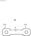
- FIG. 1 is a diagram illustrating a fuse in the related art.
- the fuse 10 in the related art is configured to include contacts 11-1 and 11-2 and a coil 12.
- the fuse 10 is heated and when the coil 12 melts by heat, electrical connection between the contacts 11-1 and 11-2 is interrupted.
- the fuse 10 in the related art can not be recycled because the coil 12 melts once the electrical connection is cut off and the fuse 10 needs to be particularly replaced with a new fuse. Since such a replacement operation is performed by hand, maintenance personnel is required and labor cost, material cost, and the like are required for every replacement. In addition, such a replacement operation takes one to two days, which makes it impossible to use a circuit including the corresponding fuse during the replacement operation.
- An object of the present invention is to provide a recyclable fuse which electrically connects a first contact and a second contact with each other to allow current to flow when a temperature is less than a predetermined first temperature, electrically interrupts the first contact and the second contact from each other to prevent the current from flowing when the temperature is equal to or more than the predetermined first temperature, and electrically interrupts the first contact and the second contact from each other and thereafter, electrically connects the first contact and the second contact to each other again when the temperature is recovered to the temperature less than the predetermined first temperature to recycle a fuse twice or more and reduce maintenance personnel and cost due to replacement of the fuse.
- a recyclable fuse may include: a first contact and a second contact in which current flows when the first contact and the second contact are electrically connected with each other; and a current control unit allowing the current to flow by electrically connecting the first contact and the second contact with each other when a temperature of the current control unit is less than a predetermined first temperature and preventing the current from flowing by electrically interrupting the first contact and the second contact from each other when the temperature of the current control unit is equal to or more than the predetermined first temperature, and the current control unit may electrically interrupt the first contact and the second contact and thereafter, when the temperature of the current control unit is recovered to a temperature less than the predetermined first temperature, the current control unit may electrically connect the first contact and the second contact to each other again.
- the current control unit may be formed by two or more metals having different thermal expansion coefficients and the current control unit may be bent toward a metal having a low thermal expansion coefficient when the temperature of the current control unit is equal to or more than the predetermined first temperature and contact between the first contact and the current control unit may be separated to electrically interrupt the first contact and the second contact.
- the recyclable fuse may further include a bonding portion which is formed at a contact point between the first contact and the current control unit and which is in a solidified state showing a bonding property such that the contact between the first contact and the second contact is maintained when the temperature of the current control unit is less than the predetermined second temperature, which is in a softened state showing viscoelasticity such that the contact between the first contact and the second contact is separated when the temperature of the current control unit is equal to or more than the predetermined second temperature, and which is in the solidified state again when the temperature of the current control unit is recovered to a temperature less than the predetermined second temperature after the bonding portion is in the softened state showing the viscoelasticity.
- the bonding portion may include a material having electrical conductivity.
- the bonding portion may include a vinyl acetate-based adhesive.
- the predetermined first temperature may be higher than the predetermined second temperature.
- the recyclable fuse may further include an insulating unit provided between the first contact and the second contact.
- the current control unit may be formed in a part of the first contact.
- a plurality of current control units may be provided.
- a recyclable fuse which electrically connects a first contact and a second contact with each other to allow current to flow when a temperature of the recyclable fuse is less than a predetermined first temperature, electrically interrupts the first contact and the second contact from each other to prevent the current from flowing when the temperature is equal to or more than the predetermined first temperature, and electrically interrupts the first contact and the second contact from each other and thereafter, electrically connects the first contact and the second contact to each other again when the temperature is recovered to the temperature less than the predetermined first temperature to recycle a fuse twice or more and reduce maintenance personnel and cost due to replacement of the fuse.
- unit means a unit that processes at least one function or operation, and the unit may be implemented by hardware or software or a combination of hardware and software.
- FIGS. 2 to 4 a configuration of a recyclable fuse 100 according to an embodiment of the present invention will be described and an example in which the recyclable fuse 100 is electrically interrupted and then recovered to be electrically connected again will be described.
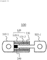
- FIG. 2 is a diagram illustrating a recyclable fuse according to an embodiment of the present invention
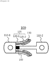
- FIG. 3 is a diagram illustrating a case where a bonding portion of the recyclable fuse according to the embodiment of the present invention melts and is softened
- FIG. 4 is a diagram illustrating a case where a current control unit of the recyclable fuse according to the embodiment of the present invention is bent to electrically interrupt a first contact and a second contact from each other.
- the recyclable fuse 100 is configured to include a first contact 110-1, a second contact 110-2, a current control unit 120, a bonding portion 130, and an insulating unit 140.
- the recyclable fuse 100 illustrated in FIG. 2 follows the embodiment and constituent elements illustrated in FIG. 2 are not limited to the embodiment illustrated in FIG. 2 and as necessary, the constituent elements may be added, modified, or deleted.
- the first contact portion 110-1 and the second contact portion 110-2 are formed with screw holes to be fixed to a desired circuit through screws and when the first and second contacts 110-1 and 110-2 need to be replaced, the first and second contacts 110-1 and 110-2 may be easily replaced.
- the current control unit 120 electrically connects the first contact 110-1 and the second contact 110-2 to each other to allow the current to flow when a temperature is less than a predetermined first temperature and electrically interrupts the first contact 110-1 and the second contact 110-2 from each other to prevent the current from flowing when the predetermined temperature is equal to or more than the predetermined first temperature.
- the current control unit 120 electrically interrupts the first contact 110-1 and the second contact 110-2 from each other and thereafter, electrically connects the first contact 110-1 and the second contact 110-2 to each other again when the temperature is recovered to the temperature less than the predetermined first temperature.
- the current control unit 120 is formed by two or more metals 120-1 and 120-2 having different thermal expansion coefficients, and when the temperature is equal to or more than the predetermined first temperature, the current control unit 120 is bent to the metal 120-1 having a low thermal expansion coefficient to separate contact between the first contact 110-1 and the second contact 110-2, thereby electrically interrupting the first contact 110-1 and the second contact 110-2. That is, when the metal 120-1 of the metals 120-1 and 120-2 constituting the current control unit 120 has a thermal expansion coefficient lower than the metal 120-2 and when the current control unit 120 is heated by the overcurrent, the current control unit 120 is bent toward the metal 120-1 because the metal 120-2 is gradually expanded more than the metal 120-1 as the temperature rises.
- the predetermined first temperature is a temperature at when the first control unit 120 is bent toward the metal 120-1 having the low thermal expansion coefficient and the first contact 110-1 and the second contact 110-2 are electrically interrupted and a producer or a user changes a combination of the metals 120-1 and 120-2 used in the current control unit 120 as necessary to set the predetermined first temperature.
- the current control unit 120 may be formed in a part of the first contact 110-1 as illustrated in FIGS. 2 to 4 .
- the current control unit 120 contacts the second contact 110-2 and when the temperature is equal to or higher than the predetermined first temperature, the current control unit 120 is bent toward the metal 120-1 having the low thermal expansion coefficient and is separated from the second contact 110-2.
- a plurality of current control units 120 may be provided.
- FIGS. 2 to 4 an example in which two current control units 120 are provided is illustrated, but three or more current control units 120 may be provided as needed. Since the recyclable fuse 100 according to the embodiment of the present invention is configured such that the current is cut off when the contact of the current control unit 120 is completely disconnected, when the number of current control units 120 increases, the current may be cut off more carefully.
- the bonding portion 130 is formed at a contact point between the first contact 110-1 and the current control unit 120 and is in a solidified state showing a bonding property such that the contact between the first contact 110-1 and the current control unit 120 may be maintained when the temperature of the current control unit 120 is less than the predetermined second temperature, is in a softened state showing viscoelasticity so that the contact between the first contact portion 110-1 and the current control unit 120 is separated when the temperature is equal to or more than the predetermined second temperature, and is in the solidified state again when temperature is recovered to a temperature less than the predetermined second temperature after the bonding portion 130 is in the softened state showing the viscoelasticity.
- the predetermined second temperature is a temperature when the bonding portion 130 is heated and is in the softened state as the temperature rises and the producer or the user changes a combination of materials used for the bonding portion 130 as necessary to set the predetermined second temperature.
- the material As described above, as a material that is in the solidified state showing a bonding property at a room temperature and is softened to be in the softened state having the viscoelasticity by losing the bonding property when the temperature becomes a high temperature of 40°C or more as heat is applied, there is a vinyl acetate-based adhesive and the material may be included in the bonding portion 130.
- the predetermined first temperature is higher than the predetermined second temperature. Accordingly, when the recyclable fuse 100 according to the embodiment of the present invention is heated, the recycle fuse 100 first reaches the predetermined second temperature and the bonding portion 130 is softened to deteriorate the bonding property and then, the current control unit 120 may be bent by reaching the predetermined first temperature.
- the bonding portion 130 may include a material having electrical conductivity. As described above, as the bonding portion 130 includes the material having the electrical conductivity, when the bonding portion 130 maintains the contact between the first contact 110-1 and the current control unit 120 in the solidified state showing the bonding property, the current may flow between the first contact 110-1 and the second contact 110-2.
- the insulating unit 140 is provided between the first contact 110-1 and the second contact 110-2.
- the insulating unit 140 serves to interrupt the first contact 110-1 and the second contact 110-2 from each other so as to prevent the current from flowing between the first contact 110-1 and the second contact 110-2.
- the contact between the first contact 110-1 and the current control unit 120 is maintained at the room temperature, and as a result, the current may flow between the first contact 110-1 and the second contact 110-2.
- the recyclable fuse 100 reaches the predetermined second temperature and the bonding portion 130 becomes the softened state showing the viscoelasticity as illustrated in FIG. 3 .
- the current control unit 120 is bent toward the metal 120-1 having the low thermal expansion coefficient and the contact between the first contact 110-1 and the second contact 110-2 is separated to electrically interrupt the first contact 110-1 and the second contact 110-2 as illustrated in FIG. 4 .
- the current control unit 120 is restored to an original state as illustrated in FIG. 3 from a bent state.
- the bonding portion 130 is restored to the solidified state showing the bonding property again as illustrated in FIG. 2 , so that the contact between the first contact portion 110-1 and the second contact portion 110-2 may be maintained.
- the recyclable fuse 100 according to the embodiment of the present invention is restored to the original state again after the interruption through the process, it is possible to recycle the recyclable fuse 100 two times or more and to reduce maintenance personnel and cost due to the replacement of the fuse.
Landscapes
- Physics & Mathematics (AREA)
- Thermal Sciences (AREA)
- Chemical & Material Sciences (AREA)
- Engineering & Computer Science (AREA)
- Combustion & Propulsion (AREA)
- Fuses (AREA)
- Thermally Actuated Switches (AREA)
Abstract
Description
- This application claims priority to and the benefit of Korean Patent Application No.
10-2016-0181540 - The present invention relates to a recyclable fuse, and to a recyclable fuse which electrically connects a first contact and a second contact with each other to allow current to flow when a temperature of the recyclable fuse is less than a predetermined first temperature, electrically interrupts the first contact and the second contact from each other to prevent the current from flowing when the temperature is equal to or more than the predetermined first temperature, and electrically interrupts the first contact and the second contact from each other and thereafter, electrically connects the first contact and the second contact to each other again when the temperature is recovered to the temperature less than the predetermined first temperature to recycle a fuse twice or more and reduce maintenance personnel and cost due to replacement of the fuse.
- A fuse, which is one of electronic components, is a device that automatically cuts off excessive currents of a specified value or more in a wire to prevent the excessive currents from continuously flowing. When overcurrent flows, the fuse is melted and cut off due to heat generated by current.
- The fuse serves as a circuit breaker that protects electrical or electronic equipment and wiring and mainly uses lead and tin or an alloy of zinc and tin which have a low melting point as materials. However, in the case of tungsten which has a very high melting point, a threadlike thin tungsten wire is made through precision machining to be used as a fuse for micro current.
-
FIG. 1 is a diagram illustrating a fuse in the related art. - Referring to
FIG. 1 , thefuse 10 in the related art is configured to include contacts 11-1 and 11-2 and acoil 12. When the overcurrent flows on thefuse 10, thefuse 10 is heated and when thecoil 12 melts by heat, electrical connection between the contacts 11-1 and 11-2 is interrupted. - As described above, the
fuse 10 in the related art can not be recycled because thecoil 12 melts once the electrical connection is cut off and thefuse 10 needs to be particularly replaced with a new fuse. Since such a replacement operation is performed by hand, maintenance personnel is required and labor cost, material cost, and the like are required for every replacement. In addition, such a replacement operation takes one to two days, which makes it impossible to use a circuit including the corresponding fuse during the replacement operation. - An object of the present invention is to provide a recyclable fuse which electrically connects a first contact and a second contact with each other to allow current to flow when a temperature is less than a predetermined first temperature, electrically interrupts the first contact and the second contact from each other to prevent the current from flowing when the temperature is equal to or more than the predetermined first temperature, and electrically interrupts the first contact and the second contact from each other and thereafter, electrically connects the first contact and the second contact to each other again when the temperature is recovered to the temperature less than the predetermined first temperature to recycle a fuse twice or more and reduce maintenance personnel and cost due to replacement of the fuse.
- According to an embodiment of the present invention, a recyclable fuse may include: a first contact and a second contact in which current flows when the first contact and the second contact are electrically connected with each other; and a current control unit allowing the current to flow by electrically connecting the first contact and the second contact with each other when a temperature of the current control unit is less than a predetermined first temperature and preventing the current from flowing by electrically interrupting the first contact and the second contact from each other when the temperature of the current control unit is equal to or more than the predetermined first temperature, and the current control unit may electrically interrupt the first contact and the second contact and thereafter, when the temperature of the current control unit is recovered to a temperature less than the predetermined first temperature, the current control unit may electrically connect the first contact and the second contact to each other again.
- The current control unit may be formed by two or more metals having different thermal expansion coefficients and the current control unit may be bent toward a metal having a low thermal expansion coefficient when the temperature of the current control unit is equal to or more than the predetermined first temperature and contact between the first contact and the current control unit may be separated to electrically interrupt the first contact and the second contact.
- The recyclable fuse may further include a bonding portion which is formed at a contact point between the first contact and the current control unit and which is in a solidified state showing a bonding property such that the contact between the first contact and the second contact is maintained when the temperature of the current control unit is less than the predetermined second temperature, which is in a softened state showing viscoelasticity such that the contact between the first contact and the second contact is separated when the temperature of the current control unit is equal to or more than the predetermined second temperature, and which is in the solidified state again when the temperature of the current control unit is recovered to a temperature less than the predetermined second temperature after the bonding portion is in the softened state showing the viscoelasticity.
- The bonding portion may include a material having electrical conductivity.
- The bonding portion may include a vinyl acetate-based adhesive.
- The predetermined first temperature may be higher than the predetermined second temperature.
- The recyclable fuse may further include an insulating unit provided between the first contact and the second contact.
- The current control unit may be formed in a part of the first contact.
- A plurality of current control units may be provided.
- According to an aspect of the present invention, it is possible to provide a recyclable fuse which electrically connects a first contact and a second contact with each other to allow current to flow when a temperature of the recyclable fuse is less than a predetermined first temperature, electrically interrupts the first contact and the second contact from each other to prevent the current from flowing when the temperature is equal to or more than the predetermined first temperature, and electrically interrupts the first contact and the second contact from each other and thereafter, electrically connects the first contact and the second contact to each other again when the temperature is recovered to the temperature less than the predetermined first temperature to recycle a fuse twice or more and reduce maintenance personnel and cost due to replacement of the fuse.
-
-
FIG. 1 is a diagram illustrating a fuse in the related art. -
FIG. 2 is a diagram illustrating a recyclable fuse according to an embodiment of the present invention. -
FIG. 3 is a diagram illustrating a case where a bonding portion of the recyclable fuse according to the embodiment of the present invention melts and is softened. -
FIG. 4 is a diagram illustrating a case where a current control unit of the recyclable fuse according to the embodiment of the present invention is bent to electrically interrupt a first contact and a second contact from each other. - The present invention will be described below in detail with reference to the accompanying drawings. Herein, the repeated description and the detailed description of publicly-known function and configuration that may make the gist of the present invention unnecessarily ambiguous will be omitted. Embodiments of the present invention are provided for more completely describing the present invention to those skilled in the art. Accordingly, shapes, sizes, and the like of elements in the drawings may be exaggerated for clearer explanation.
- Throughout the specification, unless explicitly described to the contrary, a case where any part "includes" any component will be understood to imply the inclusion of stated components but not the exclusion of any other component.
- In addition, the term "unit" disclosed in the specification means a unit that processes at least one function or operation, and the unit may be implemented by hardware or software or a combination of hardware and software.
- Hereinafter, referring to
FIGS. 2 to 4 , a configuration of arecyclable fuse 100 according to an embodiment of the present invention will be described and an example in which therecyclable fuse 100 is electrically interrupted and then recovered to be electrically connected again will be described. -
FIG. 2 is a diagram illustrating a recyclable fuse according to an embodiment of the present invention,FIG. 3 is a diagram illustrating a case where a bonding portion of the recyclable fuse according to the embodiment of the present invention melts and is softened, andFIG. 4 is a diagram illustrating a case where a current control unit of the recyclable fuse according to the embodiment of the present invention is bent to electrically interrupt a first contact and a second contact from each other. - Referring to
FIGS. 2 to 4 , therecyclable fuse 100 according to the embodiment of the present invention is configured to include a first contact 110-1, a second contact 110-2, acurrent control unit 120, abonding portion 130, and aninsulating unit 140. Therecyclable fuse 100 illustrated inFIG. 2 follows the embodiment and constituent elements illustrated inFIG. 2 are not limited to the embodiment illustrated inFIG. 2 and as necessary, the constituent elements may be added, modified, or deleted. - When the first contact 110-1 and the second contact 110-2 are electrically connected to each other, current flows. The first contact portion 110-1 and the second contact portion 110-2 are formed with screw holes to be fixed to a desired circuit through screws and when the first and second contacts 110-1 and 110-2 need to be replaced, the first and second contacts 110-1 and 110-2 may be easily replaced.
- The
current control unit 120 electrically connects the first contact 110-1 and the second contact 110-2 to each other to allow the current to flow when a temperature is less than a predetermined first temperature and electrically interrupts the first contact 110-1 and the second contact 110-2 from each other to prevent the current from flowing when the predetermined temperature is equal to or more than the predetermined first temperature. In addition, thecurrent control unit 120 electrically interrupts the first contact 110-1 and the second contact 110-2 from each other and thereafter, electrically connects the first contact 110-1 and the second contact 110-2 to each other again when the temperature is recovered to the temperature less than the predetermined first temperature. - In the embodiment, the
current control unit 120 is formed by two or more metals 120-1 and 120-2 having different thermal expansion coefficients, and when the temperature is equal to or more than the predetermined first temperature, thecurrent control unit 120 is bent to the metal 120-1 having a low thermal expansion coefficient to separate contact between the first contact 110-1 and the second contact 110-2, thereby electrically interrupting the first contact 110-1 and the second contact 110-2. That is, when the metal 120-1 of the metals 120-1 and 120-2 constituting thecurrent control unit 120 has a thermal expansion coefficient lower than the metal 120-2 and when thecurrent control unit 120 is heated by the overcurrent, thecurrent control unit 120 is bent toward the metal 120-1 because the metal 120-2 is gradually expanded more than the metal 120-1 as the temperature rises.FIG. 4 illustrates a case when thecurrent control unit 120 is bent toward the metal 120-1 having the low thermal expansion coefficient and the contact between the first contact 110-1 and the second contact 110-2 is separated to electrically interrupt the first contact 110-1 and the second contact 110-2. The predetermined first temperature is a temperature at when thefirst control unit 120 is bent toward the metal 120-1 having the low thermal expansion coefficient and the first contact 110-1 and the second contact 110-2 are electrically interrupted and a producer or a user changes a combination of the metals 120-1 and 120-2 used in thecurrent control unit 120 as necessary to set the predetermined first temperature. - In the embodiment, the
current control unit 120 may be formed in a part of the first contact 110-1 as illustrated inFIGS. 2 to 4 . When the temperature is lower than the predetermined first temperature, thecurrent control unit 120 contacts the second contact 110-2 and when the temperature is equal to or higher than the predetermined first temperature, thecurrent control unit 120 is bent toward the metal 120-1 having the low thermal expansion coefficient and is separated from the second contact 110-2. - In the embodiment, a plurality of
current control units 120 may be provided. InFIGS. 2 to 4 , an example in which twocurrent control units 120 are provided is illustrated, but three or morecurrent control units 120 may be provided as needed. Since therecyclable fuse 100 according to the embodiment of the present invention is configured such that the current is cut off when the contact of thecurrent control unit 120 is completely disconnected, when the number ofcurrent control units 120 increases, the current may be cut off more carefully. - The
bonding portion 130 is formed at a contact point between the first contact 110-1 and thecurrent control unit 120 and is in a solidified state showing a bonding property such that the contact between the first contact 110-1 and thecurrent control unit 120 may be maintained when the temperature of thecurrent control unit 120 is less than the predetermined second temperature, is in a softened state showing viscoelasticity so that the contact between the first contact portion 110-1 and thecurrent control unit 120 is separated when the temperature is equal to or more than the predetermined second temperature, and is in the solidified state again when temperature is recovered to a temperature less than the predetermined second temperature after thebonding portion 130 is in the softened state showing the viscoelasticity.FIG. 3 illustrates a case where the temperature of thecurrent control unit 120 is equal to or more than the predetermined second temperature and thebonding portion 130 is in the softened state showing the viscoelasticity. The predetermined second temperature is a temperature when thebonding portion 130 is heated and is in the softened state as the temperature rises and the producer or the user changes a combination of materials used for thebonding portion 130 as necessary to set the predetermined second temperature. As described above, as a material that is in the solidified state showing a bonding property at a room temperature and is softened to be in the softened state having the viscoelasticity by losing the bonding property when the temperature becomes a high temperature of 40°C or more as heat is applied, there is a vinyl acetate-based adhesive and the material may be included in thebonding portion 130. - In the embodiment, the predetermined first temperature is higher than the predetermined second temperature. Accordingly, when the recyclable fuse 100 according to the embodiment of the present invention is heated, the
recycle fuse 100 first reaches the predetermined second temperature and thebonding portion 130 is softened to deteriorate the bonding property and then, thecurrent control unit 120 may be bent by reaching the predetermined first temperature. - In the embodiment, the
bonding portion 130 may include a material having electrical conductivity. As described above, as thebonding portion 130 includes the material having the electrical conductivity, when thebonding portion 130 maintains the contact between the first contact 110-1 and thecurrent control unit 120 in the solidified state showing the bonding property, the current may flow between the first contact 110-1 and the second contact 110-2. - The insulating
unit 140 is provided between the first contact 110-1 and the second contact 110-2. When the contact between the first contact 110-1 and thecurrent control unit 120 is disconnected, the insulatingunit 140 serves to interrupt the first contact 110-1 and the second contact 110-2 from each other so as to prevent the current from flowing between the first contact 110-1 and the second contact 110-2. - Referring back to
FIGS. 2 to 4 , a process in which therecyclable fuse 100 according to the embodiment of the present invention is electrically interrupted and then, is restored to be electrically connected will be summarized and described. - First, as illustrated in
FIG. 2 , in therecyclable fuse 100, the contact between the first contact 110-1 and thecurrent control unit 120 is maintained at the room temperature, and as a result, the current may flow between the first contact 110-1 and the second contact 110-2. - In addition, when the overcurrent flows, the
recyclable fuse 100 reaches the predetermined second temperature and thebonding portion 130 becomes the softened state showing the viscoelasticity as illustrated inFIG. 3 . - Then, when the
recyclable fuse 100 reaches the predetermined first temperature, thecurrent control unit 120 is bent toward the metal 120-1 having the low thermal expansion coefficient and the contact between the first contact 110-1 and the second contact 110-2 is separated to electrically interrupt the first contact 110-1 and the second contact 110-2 as illustrated inFIG. 4 . - When the temperature of the
recyclable fuse 100 drops to a temperature less than the predetermined first temperature after a period of time after the interruption, thecurrent control unit 120 is restored to an original state as illustrated inFIG. 3 from a bent state. - In addition, when the temperature of the
recyclable fuse 100 drops to a temperature less than the predetermined second temperature, thebonding portion 130 is restored to the solidified state showing the bonding property again as illustrated inFIG. 2 , so that the contact between the first contact portion 110-1 and the second contact portion 110-2 may be maintained. - Since the
recyclable fuse 100 according to the embodiment of the present invention is restored to the original state again after the interruption through the process, it is possible to recycle therecyclable fuse 100 two times or more and to reduce maintenance personnel and cost due to the replacement of the fuse. - Hereinabove, a specific embodiment of the present invention has been illustrated and described, but the technical spirit of the present invention is not limited to the accompanying drawings and the described contents and it is apparent to those skilled in the art that various modifications of the present invention can be made within the scope without departing from the spirit of the present invention and it will be regarded that the modifications are included in the claims of the present invention without departing from the spirit of the present invention.
Claims (9)
- A recyclable fuse comprising:a first contact and a second contact in which current flows when the first contact and the second contact are electrically connected with each other; anda current control unit allowing the current to flow by electrically connecting the first contact and the second contact with each other when a temperature of the current control unit is less than a predetermined first temperature and preventing the current from flowing by electrically interrupting the first contact and the second contact from each other when the temperature of the current control unit is equal to or more than the predetermined first temperature,wherein the current control unit electrically interrupts the first contact and the second contact and thereafter, when the temperature of the current control unit is recovered to a temperature less than the predetermined first temperature, the current control unit electrically connects the first contact and the second contact to each other again.
- The recyclable fuse of claim 1, wherein the current control unit is formed by two or more metals having different thermal expansion coefficients and the current control unit is bent toward a metal having a low thermal expansion coefficient when the temperature of the current control unit is equal to or more than the predetermined first temperature and contact between the first contact and the current control unit is separated to electrically interrupt the first contact and the second contact.
- The recyclable fuse of claim 1, further comprising:
a bonding portion which is formed at a contact point between the first contact and the current control unit and which is in a solidified state showing a bonding property such that the contact between the first contact and the second contact is maintained when the temperature of the current control unit is less than the predetermined second temperature, is in a softened state showing viscoelasticity when the temperature of the current control unit is equal to or more than the predetermined second temperature, and is in the solidified state again when the temperature of the current control unit is recovered to a temperature less than the predetermined second temperature after the bonding portion is in the softened state showing the viscoelasticity. - The recyclable fuse of claim 3, wherein the bonding portion includes a material having electrical conductivity.
- The recyclable fuse of claim 3, wherein the bonding portion includes a vinyl acetate-based adhesive.
- The recyclable fuse of claim 3, wherein the predetermined first temperature is higher than the predetermined second temperature.
- The recyclable fuse of claim 1, further comprising:
an insulating unit provided between the first contact and the second contact. - The recyclable fuse of claim 1, wherein the current control unit is formed in a part of the first contact.
- The recyclable fuse of claim 1, wherein a plurality of current control units is provided.
Applications Claiming Priority (2)
| Application Number | Priority Date | Filing Date | Title |
|---|---|---|---|
| KR1020160181540A KR102176851B1 (en) | 2016-12-28 | 2016-12-28 | Reusable fuse |
| PCT/KR2017/015136 WO2018124608A1 (en) | 2016-12-28 | 2017-12-20 | Recyclable fuse |
Publications (3)
| Publication Number | Publication Date |
|---|---|
| EP3460823A1 true EP3460823A1 (en) | 2019-03-27 |
| EP3460823A4 EP3460823A4 (en) | 2019-08-07 |
| EP3460823B1 EP3460823B1 (en) | 2020-11-18 |
Family
ID=62709529
Family Applications (1)
| Application Number | Title | Priority Date | Filing Date |
|---|---|---|---|
| EP17886254.6A Active EP3460823B1 (en) | 2016-12-28 | 2017-12-20 | Recyclable fuse |
Country Status (7)
| Country | Link |
|---|---|
| US (1) | US10957508B2 (en) |
| EP (1) | EP3460823B1 (en) |
| JP (1) | JP6730462B2 (en) |
| KR (1) | KR102176851B1 (en) |
| CN (1) | CN109314021B (en) |
| PL (1) | PL3460823T3 (en) |
| WO (1) | WO2018124608A1 (en) |
Families Citing this family (2)
| Publication number | Priority date | Publication date | Assignee | Title |
|---|---|---|---|---|
| KR20250012970A (en) * | 2023-07-18 | 2025-01-31 | 한화솔루션 주식회사 | Connector and solar power generation apparatus therewith |
| TWI904824B (en) * | 2024-08-28 | 2025-11-11 | 岳志企業有限公司 | Reusable fuses |
Family Cites Families (20)
| Publication number | Priority date | Publication date | Assignee | Title |
|---|---|---|---|---|
| US3947798A (en) * | 1975-03-05 | 1976-03-30 | Zankl Robert H | Re-usable electrical fuse |
| DE2853776A1 (en) * | 1978-12-13 | 1980-06-26 | Eaton Gmbh | TEMPERATURE-DEPENDENT ELECTRICAL CURRENT CONTROL OR LIMITING SWITCHING ELEMENT FOR ELECTRICAL DEVICES, ESPECIALLY ELECTRICALLY HEATED DEVICES |
| JPS599820A (en) | 1982-07-08 | 1984-01-19 | 松下電器産業株式会社 | Thermal protector |
| KR970055995U (en) * | 1996-03-29 | 1997-10-13 | Hughes | |
| JP2002343134A (en) | 2001-05-22 | 2002-11-29 | Masayoshi Funada | Alternative solder |
| US7071809B2 (en) | 2002-11-25 | 2006-07-04 | Honeywell International Inc. | Thermal fuse containing bimetallic sensing element |
| KR100586574B1 (en) | 2004-03-23 | 2006-06-07 | 엘에스전선 주식회사 | Bimetallic plate bonded with constant temperature coefficient material layer and overcurrent blocking device using the same |
| JP2005302465A (en) | 2004-04-09 | 2005-10-27 | Matsushita Electric Ind Co Ltd | Self-recovery protection element |
| US7209336B2 (en) * | 2004-10-02 | 2007-04-24 | Tsung-Mou Yu | Double-protection circuit protector |
| US7345570B2 (en) * | 2005-08-02 | 2008-03-18 | Uchihashi Estec Co., Ltd. | Thermoprotector |
| US20100013591A1 (en) | 2006-05-17 | 2010-01-21 | Hiroyuki Koyama | Protection Device |
| KR100920126B1 (en) | 2007-10-23 | 2009-10-07 | 이종호 | Melted Temperature Fuses with Bimetal Function |
| CN201173191Y (en) | 2008-02-26 | 2008-12-31 | 匡法荣 | Electric compressor protector |
| KR20120026201A (en) | 2010-09-09 | 2012-03-19 | (주)엠에스테크비젼 | Repeatable fuse |
| KR101223938B1 (en) | 2011-07-18 | 2013-01-21 | 김철수 | High speed response bimetal temperature fuse |
| KR20130042863A (en) | 2011-10-19 | 2013-04-29 | 센싸타테크놀러지스코리아 주식회사 | Overload protective device with ptc |
| KR101207581B1 (en) * | 2011-10-31 | 2012-12-04 | (주)엠에스테크비젼 | Repeatable fuse for preventing over-current |
| KR101376258B1 (en) | 2012-10-31 | 2014-03-25 | 천민우 | A multi-step switch using bimetal |
| CN105308709B (en) | 2013-04-19 | 2018-02-09 | 泰科电子日本合同会社 | Protection device |
| JP5742991B2 (en) * | 2014-03-11 | 2015-07-01 | デクセリアルズ株式会社 | Anisotropic conductive adhesive |
-
2016
- 2016-12-28 KR KR1020160181540A patent/KR102176851B1/en active Active
-
2017
- 2017-12-20 US US16/307,822 patent/US10957508B2/en active Active
- 2017-12-20 EP EP17886254.6A patent/EP3460823B1/en active Active
- 2017-12-20 PL PL17886254.6T patent/PL3460823T3/en unknown
- 2017-12-20 CN CN201780038596.6A patent/CN109314021B/en active Active
- 2017-12-20 WO PCT/KR2017/015136 patent/WO2018124608A1/en not_active Ceased
- 2017-12-20 JP JP2018564888A patent/JP6730462B2/en active Active
Also Published As
| Publication number | Publication date |
|---|---|
| JP2019521482A (en) | 2019-07-25 |
| PL3460823T3 (en) | 2021-03-22 |
| CN109314021B (en) | 2020-07-10 |
| JP6730462B2 (en) | 2020-07-29 |
| CN109314021A (en) | 2019-02-05 |
| EP3460823A4 (en) | 2019-08-07 |
| US10957508B2 (en) | 2021-03-23 |
| KR20180076889A (en) | 2018-07-06 |
| US20190214212A1 (en) | 2019-07-11 |
| EP3460823B1 (en) | 2020-11-18 |
| WO2018124608A1 (en) | 2018-07-05 |
| KR102176851B1 (en) | 2020-11-10 |
Similar Documents
| Publication | Publication Date | Title |
|---|---|---|
| JP4514669B2 (en) | Protection device using thermal fuse | |
| KR20200106972A (en) | Temperature controller with thermal protection function | |
| CN109923748B (en) | Switching circuit and power supply device | |
| EP3460823A1 (en) | Recyclable fuse | |
| JPS63126128A (en) | Breaker | |
| JP6905356B2 (en) | Power semiconductor module | |
| JPWO2015133538A1 (en) | Protective device | |
| JP4513030B2 (en) | Fuse element | |
| JP2003257296A (en) | Alloy type thermal fuse | |
| JP2018531499A (en) | Multistage fuse | |
| JP2018531499A6 (en) | Multistage fuse | |
| JPWO2014034287A1 (en) | fuse | |
| GB191114803A (en) | Improvements in Fusible Cut-outs for Controlling Electric Circuits. | |
| JP4387229B2 (en) | Method of using alloy-type thermal fuse and alloy-type thermal fuse | |
| TWI727472B (en) | Fuse resistor assembly and method of manufacturing the fuse resistor assembly | |
| KR102292324B1 (en) | Motor control device and motor system | |
| JP5179631B2 (en) | Power semiconductor device | |
| JP2002150906A (en) | Alloy-type thermal fuse | |
| JP6190187B2 (en) | Fuse unit | |
| JP6101908B2 (en) | Fusible alloy for thermal fuse, wire for thermal fuse and thermal fuse | |
| JP4831702B2 (en) | Power semiconductor device | |
| JP2007031775A (en) | Pb-free fusible alloy type thermal fuse | |
| JP5455674B2 (en) | Materials for electrical and electronic fuses | |
| JPH1173871A (en) | Fuse using press pattern | |
| KR20190134286A (en) | Multi-type fuse module |
Legal Events
| Date | Code | Title | Description |
|---|---|---|---|
| STAA | Information on the status of an ep patent application or granted ep patent |
Free format text: STATUS: THE INTERNATIONAL PUBLICATION HAS BEEN MADE |
|
| PUAI | Public reference made under article 153(3) epc to a published international application that has entered the european phase |
Free format text: ORIGINAL CODE: 0009012 |
|
| STAA | Information on the status of an ep patent application or granted ep patent |
Free format text: STATUS: REQUEST FOR EXAMINATION WAS MADE |
|
| 17P | Request for examination filed |
Effective date: 20181220 |
|
| AK | Designated contracting states |
Kind code of ref document: A1 Designated state(s): AL AT BE BG CH CY CZ DE DK EE ES FI FR GB GR HR HU IE IS IT LI LT LU LV MC MK MT NL NO PL PT RO RS SE SI SK SM TR |
|
| AX | Request for extension of the european patent |
Extension state: BA ME |
|
| A4 | Supplementary search report drawn up and despatched |
Effective date: 20190708 |
|
| RIC1 | Information provided on ipc code assigned before grant |
Ipc: H01H 85/04 20060101AFI20190702BHEP Ipc: H01H 37/52 20060101ALI20190702BHEP Ipc: H01H 37/76 20060101ALI20190702BHEP Ipc: H01H 85/36 20060101ALN20190702BHEP Ipc: H01H 85/20 20060101ALI20190702BHEP Ipc: H01H 37/00 20060101ALN20190702BHEP |
|
| DAV | Request for validation of the european patent (deleted) | ||
| DAX | Request for extension of the european patent (deleted) | ||
| GRAP | Despatch of communication of intention to grant a patent |
Free format text: ORIGINAL CODE: EPIDOSNIGR1 |
|
| STAA | Information on the status of an ep patent application or granted ep patent |
Free format text: STATUS: GRANT OF PATENT IS INTENDED |
|
| RIC1 | Information provided on ipc code assigned before grant |
Ipc: H01H 37/76 20060101ALI20200630BHEP Ipc: H01H 37/52 20060101ALI20200630BHEP Ipc: H01H 85/04 20060101AFI20200630BHEP Ipc: H01H 85/36 20060101ALN20200630BHEP Ipc: H01H 85/20 20060101ALI20200630BHEP Ipc: H01H 37/00 20060101ALN20200630BHEP |
|
| RIC1 | Information provided on ipc code assigned before grant |
Ipc: H01H 37/52 20060101ALI20200714BHEP Ipc: H01H 85/04 20060101AFI20200714BHEP Ipc: H01H 85/36 20060101ALN20200714BHEP Ipc: H01H 37/00 20060101ALN20200714BHEP Ipc: H01H 37/76 20060101ALI20200714BHEP Ipc: H01H 85/20 20060101ALI20200714BHEP |
|
| INTG | Intention to grant announced |
Effective date: 20200729 |
|
| GRAS | Grant fee paid |
Free format text: ORIGINAL CODE: EPIDOSNIGR3 |
|
| GRAA | (expected) grant |
Free format text: ORIGINAL CODE: 0009210 |
|
| STAA | Information on the status of an ep patent application or granted ep patent |
Free format text: STATUS: THE PATENT HAS BEEN GRANTED |
|
| AK | Designated contracting states |
Kind code of ref document: B1 Designated state(s): AL AT BE BG CH CY CZ DE DK EE ES FI FR GB GR HR HU IE IS IT LI LT LU LV MC MK MT NL NO PL PT RO RS SE SI SK SM TR |
|
| REG | Reference to a national code |
Ref country code: GB Ref legal event code: FG4D |
|
| REG | Reference to a national code |
Ref country code: CH Ref legal event code: EP |
|
| REG | Reference to a national code |
Ref country code: IE Ref legal event code: FG4D |
|
| REG | Reference to a national code |
Ref country code: DE Ref legal event code: R096 Ref document number: 602017028024 Country of ref document: DE |
|
| REG | Reference to a national code |
Ref country code: AT Ref legal event code: REF Ref document number: 1336675 Country of ref document: AT Kind code of ref document: T Effective date: 20201215 |
|
| REG | Reference to a national code |
Ref country code: AT Ref legal event code: MK05 Ref document number: 1336675 Country of ref document: AT Kind code of ref document: T Effective date: 20201118 |
|
| REG | Reference to a national code |
Ref country code: NL Ref legal event code: MP Effective date: 20201118 |
|
| PG25 | Lapsed in a contracting state [announced via postgrant information from national office to epo] |
Ref country code: NO Free format text: LAPSE BECAUSE OF FAILURE TO SUBMIT A TRANSLATION OF THE DESCRIPTION OR TO PAY THE FEE WITHIN THE PRESCRIBED TIME-LIMIT Effective date: 20210218 Ref country code: GR Free format text: LAPSE BECAUSE OF FAILURE TO SUBMIT A TRANSLATION OF THE DESCRIPTION OR TO PAY THE FEE WITHIN THE PRESCRIBED TIME-LIMIT Effective date: 20210219 Ref country code: FI Free format text: LAPSE BECAUSE OF FAILURE TO SUBMIT A TRANSLATION OF THE DESCRIPTION OR TO PAY THE FEE WITHIN THE PRESCRIBED TIME-LIMIT Effective date: 20201118 Ref country code: PT Free format text: LAPSE BECAUSE OF FAILURE TO SUBMIT A TRANSLATION OF THE DESCRIPTION OR TO PAY THE FEE WITHIN THE PRESCRIBED TIME-LIMIT Effective date: 20210318 Ref country code: RS Free format text: LAPSE BECAUSE OF FAILURE TO SUBMIT A TRANSLATION OF THE DESCRIPTION OR TO PAY THE FEE WITHIN THE PRESCRIBED TIME-LIMIT Effective date: 20201118 |
|
| PG25 | Lapsed in a contracting state [announced via postgrant information from national office to epo] |
Ref country code: IS Free format text: LAPSE BECAUSE OF FAILURE TO SUBMIT A TRANSLATION OF THE DESCRIPTION OR TO PAY THE FEE WITHIN THE PRESCRIBED TIME-LIMIT Effective date: 20210318 Ref country code: LV Free format text: LAPSE BECAUSE OF FAILURE TO SUBMIT A TRANSLATION OF THE DESCRIPTION OR TO PAY THE FEE WITHIN THE PRESCRIBED TIME-LIMIT Effective date: 20201118 Ref country code: BG Free format text: LAPSE BECAUSE OF FAILURE TO SUBMIT A TRANSLATION OF THE DESCRIPTION OR TO PAY THE FEE WITHIN THE PRESCRIBED TIME-LIMIT Effective date: 20210218 Ref country code: AT Free format text: LAPSE BECAUSE OF FAILURE TO SUBMIT A TRANSLATION OF THE DESCRIPTION OR TO PAY THE FEE WITHIN THE PRESCRIBED TIME-LIMIT Effective date: 20201118 |
|
| REG | Reference to a national code |
Ref country code: LT Ref legal event code: MG9D |
|
| PG25 | Lapsed in a contracting state [announced via postgrant information from national office to epo] |
Ref country code: HR Free format text: LAPSE BECAUSE OF FAILURE TO SUBMIT A TRANSLATION OF THE DESCRIPTION OR TO PAY THE FEE WITHIN THE PRESCRIBED TIME-LIMIT Effective date: 20201118 |
|
| PG25 | Lapsed in a contracting state [announced via postgrant information from national office to epo] |
Ref country code: RO Free format text: LAPSE BECAUSE OF FAILURE TO SUBMIT A TRANSLATION OF THE DESCRIPTION OR TO PAY THE FEE WITHIN THE PRESCRIBED TIME-LIMIT Effective date: 20201118 Ref country code: SK Free format text: LAPSE BECAUSE OF FAILURE TO SUBMIT A TRANSLATION OF THE DESCRIPTION OR TO PAY THE FEE WITHIN THE PRESCRIBED TIME-LIMIT Effective date: 20201118 Ref country code: SM Free format text: LAPSE BECAUSE OF FAILURE TO SUBMIT A TRANSLATION OF THE DESCRIPTION OR TO PAY THE FEE WITHIN THE PRESCRIBED TIME-LIMIT Effective date: 20201118 Ref country code: LT Free format text: LAPSE BECAUSE OF FAILURE TO SUBMIT A TRANSLATION OF THE DESCRIPTION OR TO PAY THE FEE WITHIN THE PRESCRIBED TIME-LIMIT Effective date: 20201118 Ref country code: EE Free format text: LAPSE BECAUSE OF FAILURE TO SUBMIT A TRANSLATION OF THE DESCRIPTION OR TO PAY THE FEE WITHIN THE PRESCRIBED TIME-LIMIT Effective date: 20201118 Ref country code: CZ Free format text: LAPSE BECAUSE OF FAILURE TO SUBMIT A TRANSLATION OF THE DESCRIPTION OR TO PAY THE FEE WITHIN THE PRESCRIBED TIME-LIMIT Effective date: 20201118 |
|
| REG | Reference to a national code |
Ref country code: CH Ref legal event code: PL |
|
| REG | Reference to a national code |
Ref country code: DE Ref legal event code: R097 Ref document number: 602017028024 Country of ref document: DE |
|
| PG25 | Lapsed in a contracting state [announced via postgrant information from national office to epo] |
Ref country code: MC Free format text: LAPSE BECAUSE OF FAILURE TO SUBMIT A TRANSLATION OF THE DESCRIPTION OR TO PAY THE FEE WITHIN THE PRESCRIBED TIME-LIMIT Effective date: 20201118 Ref country code: DK Free format text: LAPSE BECAUSE OF FAILURE TO SUBMIT A TRANSLATION OF THE DESCRIPTION OR TO PAY THE FEE WITHIN THE PRESCRIBED TIME-LIMIT Effective date: 20201118 |
|
| REG | Reference to a national code |
Ref country code: BE Ref legal event code: MM Effective date: 20201231 |
|
| PLBE | No opposition filed within time limit |
Free format text: ORIGINAL CODE: 0009261 |
|
| STAA | Information on the status of an ep patent application or granted ep patent |
Free format text: STATUS: NO OPPOSITION FILED WITHIN TIME LIMIT |
|
| 26N | No opposition filed |
Effective date: 20210819 |
|
| PG25 | Lapsed in a contracting state [announced via postgrant information from national office to epo] |
Ref country code: IE Free format text: LAPSE BECAUSE OF NON-PAYMENT OF DUE FEES Effective date: 20201220 Ref country code: AL Free format text: LAPSE BECAUSE OF FAILURE TO SUBMIT A TRANSLATION OF THE DESCRIPTION OR TO PAY THE FEE WITHIN THE PRESCRIBED TIME-LIMIT Effective date: 20201118 Ref country code: NL Free format text: LAPSE BECAUSE OF FAILURE TO SUBMIT A TRANSLATION OF THE DESCRIPTION OR TO PAY THE FEE WITHIN THE PRESCRIBED TIME-LIMIT Effective date: 20201118 Ref country code: IT Free format text: LAPSE BECAUSE OF FAILURE TO SUBMIT A TRANSLATION OF THE DESCRIPTION OR TO PAY THE FEE WITHIN THE PRESCRIBED TIME-LIMIT Effective date: 20201118 Ref country code: LU Free format text: LAPSE BECAUSE OF NON-PAYMENT OF DUE FEES Effective date: 20201220 |
|
| PG25 | Lapsed in a contracting state [announced via postgrant information from national office to epo] |
Ref country code: LI Free format text: LAPSE BECAUSE OF NON-PAYMENT OF DUE FEES Effective date: 20201231 Ref country code: SI Free format text: LAPSE BECAUSE OF FAILURE TO SUBMIT A TRANSLATION OF THE DESCRIPTION OR TO PAY THE FEE WITHIN THE PRESCRIBED TIME-LIMIT Effective date: 20201118 Ref country code: CH Free format text: LAPSE BECAUSE OF NON-PAYMENT OF DUE FEES Effective date: 20201231 |
|
| PG25 | Lapsed in a contracting state [announced via postgrant information from national office to epo] |
Ref country code: ES Free format text: LAPSE BECAUSE OF FAILURE TO SUBMIT A TRANSLATION OF THE DESCRIPTION OR TO PAY THE FEE WITHIN THE PRESCRIBED TIME-LIMIT Effective date: 20201118 |
|
| PG25 | Lapsed in a contracting state [announced via postgrant information from national office to epo] |
Ref country code: IS Free format text: LAPSE BECAUSE OF FAILURE TO SUBMIT A TRANSLATION OF THE DESCRIPTION OR TO PAY THE FEE WITHIN THE PRESCRIBED TIME-LIMIT Effective date: 20210318 Ref country code: TR Free format text: LAPSE BECAUSE OF FAILURE TO SUBMIT A TRANSLATION OF THE DESCRIPTION OR TO PAY THE FEE WITHIN THE PRESCRIBED TIME-LIMIT Effective date: 20201118 Ref country code: MT Free format text: LAPSE BECAUSE OF FAILURE TO SUBMIT A TRANSLATION OF THE DESCRIPTION OR TO PAY THE FEE WITHIN THE PRESCRIBED TIME-LIMIT Effective date: 20201118 Ref country code: CY Free format text: LAPSE BECAUSE OF FAILURE TO SUBMIT A TRANSLATION OF THE DESCRIPTION OR TO PAY THE FEE WITHIN THE PRESCRIBED TIME-LIMIT Effective date: 20201118 |
|
| PG25 | Lapsed in a contracting state [announced via postgrant information from national office to epo] |
Ref country code: MK Free format text: LAPSE BECAUSE OF FAILURE TO SUBMIT A TRANSLATION OF THE DESCRIPTION OR TO PAY THE FEE WITHIN THE PRESCRIBED TIME-LIMIT Effective date: 20201118 |
|
| PG25 | Lapsed in a contracting state [announced via postgrant information from national office to epo] |
Ref country code: BE Free format text: LAPSE BECAUSE OF NON-PAYMENT OF DUE FEES Effective date: 20201231 |
|
| REG | Reference to a national code |
Ref country code: DE Ref legal event code: R081 Ref document number: 602017028024 Country of ref document: DE Owner name: LG ENERGY SOLUTION, LTD., KR Free format text: FORMER OWNER: LG CHEM, LTD., SEOUL, KR |
|
| P01 | Opt-out of the competence of the unified patent court (upc) registered |
Effective date: 20230512 |
|
| REG | Reference to a national code |
Ref country code: GB Ref legal event code: 732E Free format text: REGISTERED BETWEEN 20230824 AND 20230831 |
|
| PGFP | Annual fee paid to national office [announced via postgrant information from national office to epo] |
Ref country code: DE Payment date: 20251120 Year of fee payment: 9 |
|
| PGFP | Annual fee paid to national office [announced via postgrant information from national office to epo] |
Ref country code: GB Payment date: 20251120 Year of fee payment: 9 |
|
| PGFP | Annual fee paid to national office [announced via postgrant information from national office to epo] |
Ref country code: FR Payment date: 20251125 Year of fee payment: 9 |
|
| PGFP | Annual fee paid to national office [announced via postgrant information from national office to epo] |
Ref country code: SE Payment date: 20251121 Year of fee payment: 9 |
|
| PGFP | Annual fee paid to national office [announced via postgrant information from national office to epo] |
Ref country code: PL Payment date: 20251124 Year of fee payment: 9 |