EP3460372B1 - Wärmetauscher für fahrzeuge - Google Patents
Wärmetauscher für fahrzeuge Download PDFInfo
- Publication number
- EP3460372B1 EP3460372B1 EP18000712.2A EP18000712A EP3460372B1 EP 3460372 B1 EP3460372 B1 EP 3460372B1 EP 18000712 A EP18000712 A EP 18000712A EP 3460372 B1 EP3460372 B1 EP 3460372B1
- Authority
- EP
- European Patent Office
- Prior art keywords
- collector
- radiating mass
- heat exchanger
- radiating
- mass
- Prior art date
- Legal status (The legal status is an assumption and is not a legal conclusion. Google has not performed a legal analysis and makes no representation as to the accuracy of the status listed.)
- Active
Links
Images



Classifications
-
- F—MECHANICAL ENGINEERING; LIGHTING; HEATING; WEAPONS; BLASTING
- F28—HEAT EXCHANGE IN GENERAL
- F28D—HEAT-EXCHANGE APPARATUS, NOT PROVIDED FOR IN ANOTHER SUBCLASS, IN WHICH THE HEAT-EXCHANGE MEDIA DO NOT COME INTO DIRECT CONTACT
- F28D1/00—Heat-exchange apparatus having stationary conduit assemblies for one heat-exchange medium only, the media being in contact with different sides of the conduit wall, in which the other heat-exchange medium is a large body of fluid, e.g. domestic or motor car radiators
- F28D1/02—Heat-exchange apparatus having stationary conduit assemblies for one heat-exchange medium only, the media being in contact with different sides of the conduit wall, in which the other heat-exchange medium is a large body of fluid, e.g. domestic or motor car radiators with heat-exchange conduits immersed in the body of fluid
- F28D1/04—Heat-exchange apparatus having stationary conduit assemblies for one heat-exchange medium only, the media being in contact with different sides of the conduit wall, in which the other heat-exchange medium is a large body of fluid, e.g. domestic or motor car radiators with heat-exchange conduits immersed in the body of fluid with tubular conduits
- F28D1/0408—Multi-circuit heat exchangers, e.g. integrating different heat exchange sections in the same unit or heat exchangers for more than two fluids
- F28D1/0417—Multi-circuit heat exchangers, e.g. integrating different heat exchange sections in the same unit or heat exchangers for more than two fluids with particular circuits for the same heat exchange medium, e.g. with the heat exchange medium flowing through sections having different heat exchange capacities or for heating/cooling the heat exchange medium at different temperatures
-
- F—MECHANICAL ENGINEERING; LIGHTING; HEATING; WEAPONS; BLASTING
- F28—HEAT EXCHANGE IN GENERAL
- F28D—HEAT-EXCHANGE APPARATUS, NOT PROVIDED FOR IN ANOTHER SUBCLASS, IN WHICH THE HEAT-EXCHANGE MEDIA DO NOT COME INTO DIRECT CONTACT
- F28D1/00—Heat-exchange apparatus having stationary conduit assemblies for one heat-exchange medium only, the media being in contact with different sides of the conduit wall, in which the other heat-exchange medium is a large body of fluid, e.g. domestic or motor car radiators
- F28D1/02—Heat-exchange apparatus having stationary conduit assemblies for one heat-exchange medium only, the media being in contact with different sides of the conduit wall, in which the other heat-exchange medium is a large body of fluid, e.g. domestic or motor car radiators with heat-exchange conduits immersed in the body of fluid
- F28D1/04—Heat-exchange apparatus having stationary conduit assemblies for one heat-exchange medium only, the media being in contact with different sides of the conduit wall, in which the other heat-exchange medium is a large body of fluid, e.g. domestic or motor car radiators with heat-exchange conduits immersed in the body of fluid with tubular conduits
- F28D1/0408—Multi-circuit heat exchangers, e.g. integrating different heat exchange sections in the same unit or heat exchangers for more than two fluids
- F28D1/0426—Multi-circuit heat exchangers, e.g. integrating different heat exchange sections in the same unit or heat exchangers for more than two fluids with units having particular arrangement relative to the large body of fluid, e.g. with interleaved units or with adjacent heat exchange units in common air flow or with units extending at an angle to each other or with units arranged around a central element
-
- F—MECHANICAL ENGINEERING; LIGHTING; HEATING; WEAPONS; BLASTING
- F28—HEAT EXCHANGE IN GENERAL
- F28D—HEAT-EXCHANGE APPARATUS, NOT PROVIDED FOR IN ANOTHER SUBCLASS, IN WHICH THE HEAT-EXCHANGE MEDIA DO NOT COME INTO DIRECT CONTACT
- F28D21/00—Heat-exchange apparatus not covered by any of the groups F28D1/00 - F28D20/00
- F28D2021/0019—Other heat exchangers for particular applications; Heat exchange systems not otherwise provided for
- F28D2021/008—Other heat exchangers for particular applications; Heat exchange systems not otherwise provided for for vehicles
- F28D2021/0091—Radiators
Definitions
- the present invention refers to a heat exchanger for vehicles which can be used for cooling a thermal engine of a vehicle.
- the invention relates particularly to heat exchangers as defined in the preamble of claim 1, and as illustrated on figure 1 of EP 2 314 967 A1 .
- the invention refers to a high-efficiency radiation, which can be used to cool the cooling liquid of the thermal engine of a motorcycle, more in particular of a racing motorcycle.
- Heat exchangers for vehicles for example for motorcycles, are known, generally arranged between the wheel and the engine, which, above all in case of processed motorcycles to participate in speed competitions, must dissipate a high amount of heat to cool the cooling liquid or oil of a thermal engine.
- Object of the present invention is solving the above prior art problems, by providing a heat exchanger, which allows dissipating a high amount of heat while it occupies a reduced space.
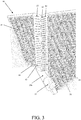
- the heat exchanger 10 for vehicles of the invention comprises a first radiating mass 21 having a first side 22 connected to a first collector 24 comprising a mouth 25 for entering a cooling fluid, and a second side 23 connected to a second collector 26 comprising a mouth 27 for exiting the cooling fluid; preferably, the first side 22 and the second side 23 are opposite sides of the first radiating mass 21.
- the heat exchanger 10 further comprises at least one second radiating mass 31 having a first side 32 connected to the first collector 24, and a second side 33 connected to a third collector 38; preferably, the first side 32 and the second side 33 are opposite sides of the second radiating mass 31.
- the heat exchanger 10 further comprises a first tank 35, having a first side 36 connected to a base side 34 of the second radiating mass 31, and a second side 37 connected to a lower portion 24a of the first collector 24; in a preferred way, the lower portion 24a of the first collector 24 is separated from an upper portion 24b of the first collector 24 by means of a separating septum 55, to optimize the flow of the fluid inside the heat exchanger 10 of the invention, as will be explained in detail below.
- the second radiating mass 31 is arranged transverse to the first radiating mass 21, forming therewith an angle ⁇ , preferably greater than 90°.
- the heat exchanger 10 for vehicles of the invention comprises deviating wings 56 of the flow associated to the second radiating mass 31, in particular associated to its inlet surface of the air flow, which is oriented towards the traveling direction of the vehicle.
- the second radiating mass 31 and the first tank 35 can be connected to the second collector 26 comprising the mouth 27 for exiting the cooling fluid.
- the heat exchanger 10 for vehicles comprises:
- the heat exchanger 10 further comprises a second tank 45, having a first side 46 connected to a base side 44 of the third radiating mass 41, and a second side 47 connected to a lower portion 26a of the second collector 26; in a preferred way, the lower portion 26a of the second collector 26 is separated from an upper portion 26b of the second collector 26 by means of a separating septum 55, to optimize the flow of fluid inside the heat exchanger 10 of the invention, as will be explained below in detail.
- the third radiating mass 41 is arranged transverse to the first radiating mass 21, more preferably symmetrical to the second radiating mass 31, forming with the first radiating mass 21 an angle ⁇ , preferably greater than 90°; more preferably, angle ⁇ is equal to angle ⁇ formed between the second radiating mass 31 and the first radiating mass 21.
- the third radiating mass 41 comprises deviating wings 56 of the flow associated thereto, in particular associate to its inlet surface of the air flow, which is oriented towards the traveling direction of the vehicle, for example towards the front part of a motorcycle on which the heat exchanger 10 of the invention is assembled, preferably with the wheel inserted in the space included between the second radiating mass 31 and the third radiating mass 41.
- the first radiating mass 21 comprises a plurality of tubes 12 which extend between the first side 22 and the second side 23 of the first radiating mass 21, said tubes 12 having a first end next to the first side 22, connected to the first collector 24 and a second end, next to the second side 23, connected to the second collector 26.
- the second radiating mass 31 comprises a plurality of tubes 12 which extend between the first side 32 and the second side 33 of the second radiating mass 31, said tubes 12 having a first end next to the first side 32, connected to the first collector 24, and a second end, next to the second side 33, connected to the third collector 38.
- the third radiating mass 41 comprises a plurality of tubes 12 which extend between the first side 42 and the second side 43 of the third radiating mass 41, said tubes 12 having a first end next to the first side 42, connected to the second collector 26, and a second end, next to the second side 43, connected to the fourth collector 48.
- the tubes 12 are arranged substantially horizontal and extend between two opposite sides of the radiating masses 21, 31, 41 and the first and second collector 24, 26 are arranged transverse to the tubes 12; in a preferred way, the tubes 12 are connected to cooling wings of a known type, for example arranged between the tubes, and are connected to a frame, comprising horizontal and transverse plates next to the sides which delimit the radiating masses 21, 31, 41.
- the deviating wings 56 of the flow are connected to the frame next to the second and the third radiating mass 31, 41.
- a vehicle according to the invention for example a motorcycle, comprises the heat exchanger 10 of the invention assembled arranged between the wheel and the thermal engine, in a preferred way with the second and the third radiating mass 31, 41 arranged laterally to the wheel.
- the cooling fluid after having entered the heat exchanger 10 through the entry mouth 25, passes into the first collector 24, in particular in its upper portion 24b, where it is divided into two parts: a first part of the flow, for example about half the flow, enters into the first radiating mass 21, and a second part of the flow, for example the second half, enters into the second radiating mass 31 and from this into the third collector 38.
- the first part of the flow then passes from the first radiating mass 21 to the second collector 26, in particular to its upper portion 26b, and from this to the third radiating mass 41 and then into the fourth collector 48.
- the second part of the flow then passes from the third collector 38 to the first tank 35 and from this it returns into the first collector 24, in particular in its lower portion 24a, and from this into the first radiating mass 21, in particular at its lower portion 21a, to enter then into the second collector 26, in particular in its lower portion 26a; from the lower portion 26a of the second collector 26, finally, the second part of the flow exits from the outlet mouth 27.
- the first part of the flow passes from the fourth collector 48 to the second tank 45 and from this it returns into the second collector 26, in particular in its lower portion 26a, to exit from the outlet mouth 27.
- the heat exchanger 10 for vehicles of the invention improves the performances, with respect to a standard heat exchanger (radiator), decreasing the temperature of the cooling fluid by 15°C, taking into account that usually in this field it is deemed an optimum result to be able to obtain a fluid temperature decrease of 5°C with modifications to the heat exchanger.
Landscapes
- Engineering & Computer Science (AREA)
- Physics & Mathematics (AREA)
- Thermal Sciences (AREA)
- Mechanical Engineering (AREA)
- General Engineering & Computer Science (AREA)
- Heat-Exchange Devices With Radiators And Conduit Assemblies (AREA)
- Cooling, Air Intake And Gas Exhaust, And Fuel Tank Arrangements In Propulsion Units (AREA)
Claims (6)
- Wärmetauscher (10) für Fahrzeuge, der Folgendes enthält:- eine erste Strahlungsmasse (21) mit einer ersten Seite (22), die mit einem ersten Kollektor (24) verbunden ist, der eine Eingangsöffnung (25) für eine Kühlflüssigkeit enthält, und einer zweiten Seite (23), die mit einem zweiten Kollektor (26) verbunden ist, der eine Ausgangsöffnung (27) für die Kühlflüssigkeit enthält,- mindestens eine zweite Strahlungsmasse (31) mit einer ersten Seite (32), die mit dem ersten Kollektor (24) verbunden ist, und einer zweiten Seite (33), die mit einem dritten Kollektor (38) verbunden ist,- außerdem einen ersten Behälter (35) mit einer ersten Seite (36), die mit einer Basisseite (34) der zweiten Strahlungsmasse (31) verbunden ist, und einer zweiten Seite (37), die mit einem ersten Kollektor (24) verbunden ist,der Wärmetauscher ist gekennzeichnet durch:- eine dritte Strahlungsmasse (41) mit einer ersten Seite (42), die mit dem zweiten Kollektor (26) verbunden ist, und einer zweiten Seite (43), die mit einem vierten Kollektor (48) verbunden ist- einen zweiten Behälter (45) mit einer ersten Seite (46), die mit einer Basisseite (44) der dritten Strahlungsmasse (41) verbunden ist, und einer zweiten Seite (47), die mit einem zweiten Kollektor (26) verbunden ist;
in dem die zweite Seite (37) des ersten Behälters (35) mit einem Unterteil (24a) des ersten Kollektors (24) verbunden ist, der von einem Oberteil (24b) des ersten Kollektors (24) durch eine Trennwand (55) getrennt ist, um den Flüssigkeitsfluss zu optimieren; und
die zweite Seite (47) des zweiten Behälters (45) mit einem Unterteil (26a) des zweiten Kollektors (26) verbunden ist, der von einem Oberteil (26b) des zweiten Kollektors (26) durch eine Trennwand (55) getrennt ist, um den Flüssigkeitsfluss zu optimieren. - Wärmetauscher (10) für Fahrzeuge gemäß Patentanspruch 1, der dadurch gekennzeichnet ist, dass die zweite Strahlungsmasse (31) und der erste Behälter (35) nicht mit dem ersten Kollektor (24), sondern mit dem zweiten Kollektor (26) verbunden sind, der die Ausgangsöffnung (27) für die Kühlflüssigkeit enthält.
- Wärmetauscher (10) für Fahrzeuge gemäß Patentanspruch 2, der dadurch gekennzeichnet ist, dass die zweite Strahlungsmasse (31) und/oder die dritte Strahlungsmasse (41) jeweils einen Winkel (α, β) bilden, der größer als 90° ist.
- Wärmetauscher (10) für Fahrzeuge gemäß Patentanspruch 3, der dadurch gekennzeichnet ist, dass die dritte Strahlungsmasse (41) symmetrisch zur zweiten Strahlungsmasse (31) angeordnet ist und mit der ersten Strahlungsmasse (21) einen Winkel (β) bildet, der dem Winkel (α) entspricht, welcher zwischen der zweiten Strahlungsmasse (31) und der ersten Strahlungsmasse (21) gebildet wird.
- Wärmetauscher (10) für Fahrzeuge gemäß einem beliebigen der vorhergehenden Patentansprüche, der dadurch gekennzeichnet ist, dass er Ableitlamellen des Flusses (56) enthält, die einer Eingangsfläche des Luftflusses der zweiten Strahlungsmasse (31) und/oder der dritten Strahlungsmasse (41) zugeordnet werden, welche in Fahrtrichtung des Fahrzeugs ausgerichtet ist.
- Fahrzeug, das einen Wärmetauscher (10) gemäß einem der vorhergehenden Patentansprüche enthält, der zwischen einem Rad und einem Wärmemotor angeordnet wird, wobei die zweite und/oder die dritte Strahlungsmasse (31, 41) seitlich zum Rad angeordnet wird/werden.
Applications Claiming Priority (1)
| Application Number | Priority Date | Filing Date | Title |
|---|---|---|---|
| IT102017000105424A IT201700105424A1 (it) | 2017-09-21 | 2017-09-21 | Scambiatore di calore per veicoli |
Publications (2)
| Publication Number | Publication Date |
|---|---|
| EP3460372A1 EP3460372A1 (de) | 2019-03-27 |
| EP3460372B1 true EP3460372B1 (de) | 2020-03-11 |
Family
ID=61006195
Family Applications (1)
| Application Number | Title | Priority Date | Filing Date |
|---|---|---|---|
| EP18000712.2A Active EP3460372B1 (de) | 2017-09-21 | 2018-09-04 | Wärmetauscher für fahrzeuge |
Country Status (3)
| Country | Link |
|---|---|
| EP (1) | EP3460372B1 (de) |
| ES (1) | ES2795230T3 (de) |
| IT (1) | IT201700105424A1 (de) |
Family Cites Families (3)
| Publication number | Priority date | Publication date | Assignee | Title |
|---|---|---|---|---|
| DE4205234C2 (de) * | 1992-02-21 | 1994-11-24 | Daimler Benz Ag | Wärmetauscher, insbesondere für Kraftfahrzeuge |
| FR2866947B1 (fr) * | 2004-02-27 | 2006-04-28 | Valeo Climatisation | Dispositif a echangeurs de chaleur combines |
| FR2951533B1 (fr) * | 2009-10-19 | 2014-09-12 | Valeo Systemes Thermiques | Echangeur de chaleur comprenant un collecteur d'entree, un collecteur de sortie et un collecteur secondaire |
-
2017
- 2017-09-21 IT IT102017000105424A patent/IT201700105424A1/it unknown
-
2018
- 2018-09-04 EP EP18000712.2A patent/EP3460372B1/de active Active
- 2018-09-04 ES ES18000712T patent/ES2795230T3/es active Active
Non-Patent Citations (1)
| Title |
|---|
| None * |
Also Published As
| Publication number | Publication date |
|---|---|
| EP3460372A1 (de) | 2019-03-27 |
| ES2795230T3 (es) | 2020-11-23 |
| IT201700105424A1 (it) | 2017-12-21 |
Similar Documents
| Publication | Publication Date | Title |
|---|---|---|
| EP3008416B1 (de) | Wärmetauscher für ein fahrzeug | |
| US10495390B2 (en) | Liquid cooling radiator with impurities filtering | |
| US5209285A (en) | Inclined tube radiator | |
| EP2315244B1 (de) | Kühlgerät mit Flüssigkeitskühlung | |
| US4640341A (en) | Radiator for vehicles, having improved mountability into vehicles | |
| JP5474265B2 (ja) | 車両用床下装置の冷却装置 | |
| US9958195B2 (en) | Heat exchanger having partition | |
| US20170328637A1 (en) | Heat exchanger with dummy tubes | |
| US7028751B2 (en) | Box-like cooling system | |
| KR102408712B1 (ko) | 차량용 쿨링모듈 | |
| JP5759762B2 (ja) | エバポレータ | |
| CN107013311B (zh) | 热交换器系统 | |
| US9327592B2 (en) | Bumper with integrated auxilliary cooler | |
| WO2014176194A1 (en) | Core device of a heat exchanger and heat exchanger with the core device | |
| EP3460372B1 (de) | Wärmetauscher für fahrzeuge | |
| CN108120120B (zh) | 蒸发器 | |
| CN106323037B (zh) | 一种高效率汽车空调用散热冷却系统 | |
| US20120247731A1 (en) | Heat exchanger assembly having a seal | |
| JP6051641B2 (ja) | 車両用インタークーラ | |
| CN106121803A (zh) | 散热器 | |
| US20130068435A1 (en) | In-line heat exchanger assembly and method of using | |
| JP2016023815A (ja) | エバポレータ | |
| JP2017101842A (ja) | 熱交換器 | |
| CN113950225A (zh) | 一种冷凝器散热机构 | |
| KR102119776B1 (ko) | 인터쿨러 파이프의 냉각 장치 |
Legal Events
| Date | Code | Title | Description |
|---|---|---|---|
| PUAI | Public reference made under article 153(3) epc to a published international application that has entered the european phase |
Free format text: ORIGINAL CODE: 0009012 |
|
| STAA | Information on the status of an ep patent application or granted ep patent |
Free format text: STATUS: THE APPLICATION HAS BEEN PUBLISHED |
|
| AK | Designated contracting states |
Kind code of ref document: A1 Designated state(s): AL AT BE BG CH CY CZ DE DK EE ES FI FR GB GR HR HU IE IS IT LI LT LU LV MC MK MT NL NO PL PT RO RS SE SI SK SM TR |
|
| AX | Request for extension of the european patent |
Extension state: BA ME |
|
| STAA | Information on the status of an ep patent application or granted ep patent |
Free format text: STATUS: REQUEST FOR EXAMINATION WAS MADE |
|
| GRAP | Despatch of communication of intention to grant a patent |
Free format text: ORIGINAL CODE: EPIDOSNIGR1 |
|
| STAA | Information on the status of an ep patent application or granted ep patent |
Free format text: STATUS: GRANT OF PATENT IS INTENDED |
|
| 17P | Request for examination filed |
Effective date: 20190829 |
|
| RBV | Designated contracting states (corrected) |
Designated state(s): AL AT BE BG CH CY CZ DE DK EE ES FI FR GB GR HR HU IE IS IT LI LT LU LV MC MK MT NL NO PL PT RO RS SE SI SK SM TR |
|
| INTG | Intention to grant announced |
Effective date: 20191004 |
|
| GRAS | Grant fee paid |
Free format text: ORIGINAL CODE: EPIDOSNIGR3 |
|
| GRAA | (expected) grant |
Free format text: ORIGINAL CODE: 0009210 |
|
| STAA | Information on the status of an ep patent application or granted ep patent |
Free format text: STATUS: THE PATENT HAS BEEN GRANTED |
|
| AK | Designated contracting states |
Kind code of ref document: B1 Designated state(s): AL AT BE BG CH CY CZ DE DK EE ES FI FR GB GR HR HU IE IS IT LI LT LU LV MC MK MT NL NO PL PT RO RS SE SI SK SM TR |
|
| REG | Reference to a national code |
Ref country code: GB Ref legal event code: FG4D |
|
| REG | Reference to a national code |
Ref country code: CH Ref legal event code: EP |
|
| REG | Reference to a national code |
Ref country code: AT Ref legal event code: REF Ref document number: 1243656 Country of ref document: AT Kind code of ref document: T Effective date: 20200315 |
|
| REG | Reference to a national code |
Ref country code: IE Ref legal event code: FG4D |
|
| REG | Reference to a national code |
Ref country code: DE Ref legal event code: R096 Ref document number: 602018002883 Country of ref document: DE |
|
| PG25 | Lapsed in a contracting state [announced via postgrant information from national office to epo] |
Ref country code: RS Free format text: LAPSE BECAUSE OF FAILURE TO SUBMIT A TRANSLATION OF THE DESCRIPTION OR TO PAY THE FEE WITHIN THE PRESCRIBED TIME-LIMIT Effective date: 20200311 Ref country code: FI Free format text: LAPSE BECAUSE OF FAILURE TO SUBMIT A TRANSLATION OF THE DESCRIPTION OR TO PAY THE FEE WITHIN THE PRESCRIBED TIME-LIMIT Effective date: 20200311 Ref country code: NO Free format text: LAPSE BECAUSE OF FAILURE TO SUBMIT A TRANSLATION OF THE DESCRIPTION OR TO PAY THE FEE WITHIN THE PRESCRIBED TIME-LIMIT Effective date: 20200611 |
|
| REG | Reference to a national code |
Ref country code: NL Ref legal event code: MP Effective date: 20200311 |
|
| PG25 | Lapsed in a contracting state [announced via postgrant information from national office to epo] |
Ref country code: HR Free format text: LAPSE BECAUSE OF FAILURE TO SUBMIT A TRANSLATION OF THE DESCRIPTION OR TO PAY THE FEE WITHIN THE PRESCRIBED TIME-LIMIT Effective date: 20200311 Ref country code: BG Free format text: LAPSE BECAUSE OF FAILURE TO SUBMIT A TRANSLATION OF THE DESCRIPTION OR TO PAY THE FEE WITHIN THE PRESCRIBED TIME-LIMIT Effective date: 20200611 Ref country code: GR Free format text: LAPSE BECAUSE OF FAILURE TO SUBMIT A TRANSLATION OF THE DESCRIPTION OR TO PAY THE FEE WITHIN THE PRESCRIBED TIME-LIMIT Effective date: 20200612 Ref country code: SE Free format text: LAPSE BECAUSE OF FAILURE TO SUBMIT A TRANSLATION OF THE DESCRIPTION OR TO PAY THE FEE WITHIN THE PRESCRIBED TIME-LIMIT Effective date: 20200311 Ref country code: LV Free format text: LAPSE BECAUSE OF FAILURE TO SUBMIT A TRANSLATION OF THE DESCRIPTION OR TO PAY THE FEE WITHIN THE PRESCRIBED TIME-LIMIT Effective date: 20200311 |
|
| REG | Reference to a national code |
Ref country code: LT Ref legal event code: MG4D |
|
| PG25 | Lapsed in a contracting state [announced via postgrant information from national office to epo] |
Ref country code: NL Free format text: LAPSE BECAUSE OF FAILURE TO SUBMIT A TRANSLATION OF THE DESCRIPTION OR TO PAY THE FEE WITHIN THE PRESCRIBED TIME-LIMIT Effective date: 20200311 |
|
| PG25 | Lapsed in a contracting state [announced via postgrant information from national office to epo] |
Ref country code: CZ Free format text: LAPSE BECAUSE OF FAILURE TO SUBMIT A TRANSLATION OF THE DESCRIPTION OR TO PAY THE FEE WITHIN THE PRESCRIBED TIME-LIMIT Effective date: 20200311 Ref country code: IS Free format text: LAPSE BECAUSE OF FAILURE TO SUBMIT A TRANSLATION OF THE DESCRIPTION OR TO PAY THE FEE WITHIN THE PRESCRIBED TIME-LIMIT Effective date: 20200711 Ref country code: SK Free format text: LAPSE BECAUSE OF FAILURE TO SUBMIT A TRANSLATION OF THE DESCRIPTION OR TO PAY THE FEE WITHIN THE PRESCRIBED TIME-LIMIT Effective date: 20200311 Ref country code: RO Free format text: LAPSE BECAUSE OF FAILURE TO SUBMIT A TRANSLATION OF THE DESCRIPTION OR TO PAY THE FEE WITHIN THE PRESCRIBED TIME-LIMIT Effective date: 20200311 Ref country code: SM Free format text: LAPSE BECAUSE OF FAILURE TO SUBMIT A TRANSLATION OF THE DESCRIPTION OR TO PAY THE FEE WITHIN THE PRESCRIBED TIME-LIMIT Effective date: 20200311 Ref country code: EE Free format text: LAPSE BECAUSE OF FAILURE TO SUBMIT A TRANSLATION OF THE DESCRIPTION OR TO PAY THE FEE WITHIN THE PRESCRIBED TIME-LIMIT Effective date: 20200311 Ref country code: PT Free format text: LAPSE BECAUSE OF FAILURE TO SUBMIT A TRANSLATION OF THE DESCRIPTION OR TO PAY THE FEE WITHIN THE PRESCRIBED TIME-LIMIT Effective date: 20200805 Ref country code: LT Free format text: LAPSE BECAUSE OF FAILURE TO SUBMIT A TRANSLATION OF THE DESCRIPTION OR TO PAY THE FEE WITHIN THE PRESCRIBED TIME-LIMIT Effective date: 20200311 |
|
| REG | Reference to a national code |
Ref country code: AT Ref legal event code: MK05 Ref document number: 1243656 Country of ref document: AT Kind code of ref document: T Effective date: 20200311 |
|
| REG | Reference to a national code |
Ref country code: ES Ref legal event code: FG2A Ref document number: 2795230 Country of ref document: ES Kind code of ref document: T3 Effective date: 20201123 |
|
| REG | Reference to a national code |
Ref country code: DE Ref legal event code: R097 Ref document number: 602018002883 Country of ref document: DE |
|
| PLBE | No opposition filed within time limit |
Free format text: ORIGINAL CODE: 0009261 |
|
| STAA | Information on the status of an ep patent application or granted ep patent |
Free format text: STATUS: NO OPPOSITION FILED WITHIN TIME LIMIT |
|
| PG25 | Lapsed in a contracting state [announced via postgrant information from national office to epo] |
Ref country code: AT Free format text: LAPSE BECAUSE OF FAILURE TO SUBMIT A TRANSLATION OF THE DESCRIPTION OR TO PAY THE FEE WITHIN THE PRESCRIBED TIME-LIMIT Effective date: 20200311 Ref country code: DK Free format text: LAPSE BECAUSE OF FAILURE TO SUBMIT A TRANSLATION OF THE DESCRIPTION OR TO PAY THE FEE WITHIN THE PRESCRIBED TIME-LIMIT Effective date: 20200311 |
|
| 26N | No opposition filed |
Effective date: 20201214 |
|
| PG25 | Lapsed in a contracting state [announced via postgrant information from national office to epo] |
Ref country code: PL Free format text: LAPSE BECAUSE OF FAILURE TO SUBMIT A TRANSLATION OF THE DESCRIPTION OR TO PAY THE FEE WITHIN THE PRESCRIBED TIME-LIMIT Effective date: 20200311 Ref country code: SI Free format text: LAPSE BECAUSE OF FAILURE TO SUBMIT A TRANSLATION OF THE DESCRIPTION OR TO PAY THE FEE WITHIN THE PRESCRIBED TIME-LIMIT Effective date: 20200311 |
|
| REG | Reference to a national code |
Ref country code: BE Ref legal event code: MM Effective date: 20200930 |
|
| PG25 | Lapsed in a contracting state [announced via postgrant information from national office to epo] |
Ref country code: LU Free format text: LAPSE BECAUSE OF NON-PAYMENT OF DUE FEES Effective date: 20200904 |
|
| PG25 | Lapsed in a contracting state [announced via postgrant information from national office to epo] |
Ref country code: IE Free format text: LAPSE BECAUSE OF NON-PAYMENT OF DUE FEES Effective date: 20200904 Ref country code: BE Free format text: LAPSE BECAUSE OF NON-PAYMENT OF DUE FEES Effective date: 20200930 |
|
| REG | Reference to a national code |
Ref country code: CH Ref legal event code: PL |
|
| PG25 | Lapsed in a contracting state [announced via postgrant information from national office to epo] |
Ref country code: TR Free format text: LAPSE BECAUSE OF FAILURE TO SUBMIT A TRANSLATION OF THE DESCRIPTION OR TO PAY THE FEE WITHIN THE PRESCRIBED TIME-LIMIT Effective date: 20200311 Ref country code: MT Free format text: LAPSE BECAUSE OF FAILURE TO SUBMIT A TRANSLATION OF THE DESCRIPTION OR TO PAY THE FEE WITHIN THE PRESCRIBED TIME-LIMIT Effective date: 20200311 Ref country code: CY Free format text: LAPSE BECAUSE OF FAILURE TO SUBMIT A TRANSLATION OF THE DESCRIPTION OR TO PAY THE FEE WITHIN THE PRESCRIBED TIME-LIMIT Effective date: 20200311 |
|
| PG25 | Lapsed in a contracting state [announced via postgrant information from national office to epo] |
Ref country code: MK Free format text: LAPSE BECAUSE OF FAILURE TO SUBMIT A TRANSLATION OF THE DESCRIPTION OR TO PAY THE FEE WITHIN THE PRESCRIBED TIME-LIMIT Effective date: 20200311 Ref country code: MC Free format text: LAPSE BECAUSE OF FAILURE TO SUBMIT A TRANSLATION OF THE DESCRIPTION OR TO PAY THE FEE WITHIN THE PRESCRIBED TIME-LIMIT Effective date: 20200311 Ref country code: AL Free format text: LAPSE BECAUSE OF FAILURE TO SUBMIT A TRANSLATION OF THE DESCRIPTION OR TO PAY THE FEE WITHIN THE PRESCRIBED TIME-LIMIT Effective date: 20200311 |
|
| PG25 | Lapsed in a contracting state [announced via postgrant information from national office to epo] |
Ref country code: LI Free format text: LAPSE BECAUSE OF NON-PAYMENT OF DUE FEES Effective date: 20210930 Ref country code: CH Free format text: LAPSE BECAUSE OF NON-PAYMENT OF DUE FEES Effective date: 20210930 |
|
| PGFP | Annual fee paid to national office [announced via postgrant information from national office to epo] |
Ref country code: DE Payment date: 20250904 Year of fee payment: 8 |
|
| PGFP | Annual fee paid to national office [announced via postgrant information from national office to epo] |
Ref country code: IT Payment date: 20250811 Year of fee payment: 8 |
|
| PGFP | Annual fee paid to national office [announced via postgrant information from national office to epo] |
Ref country code: GB Payment date: 20250929 Year of fee payment: 8 |
|
| PGFP | Annual fee paid to national office [announced via postgrant information from national office to epo] |
Ref country code: FR Payment date: 20250925 Year of fee payment: 8 |
|
| PGFP | Annual fee paid to national office [announced via postgrant information from national office to epo] |
Ref country code: ES Payment date: 20251001 Year of fee payment: 8 |