EP3460239A1 - Kabelsattel zum stützen von kabeln in einer kabelschlaufe einer windkraftanlage - Google Patents
Kabelsattel zum stützen von kabeln in einer kabelschlaufe einer windkraftanlage Download PDFInfo
- Publication number
- EP3460239A1 EP3460239A1 EP18195320.9A EP18195320A EP3460239A1 EP 3460239 A1 EP3460239 A1 EP 3460239A1 EP 18195320 A EP18195320 A EP 18195320A EP 3460239 A1 EP3460239 A1 EP 3460239A1
- Authority
- EP
- European Patent Office
- Prior art keywords
- cable
- saddle
- cables
- loop
- tower
- Prior art date
- Legal status (The legal status is an assumption and is not a legal conclusion. Google has not performed a legal analysis and makes no representation as to the accuracy of the status listed.)
- Granted
Links
Images


Classifications
-
- F—MECHANICAL ENGINEERING; LIGHTING; HEATING; WEAPONS; BLASTING
- F03—MACHINES OR ENGINES FOR LIQUIDS; WIND, SPRING, OR WEIGHT MOTORS; PRODUCING MECHANICAL POWER OR A REACTIVE PROPULSIVE THRUST, NOT OTHERWISE PROVIDED FOR
- F03D—WIND MOTORS
- F03D80/00—Details, components or accessories not provided for in groups F03D1/00 - F03D17/00
- F03D80/80—Arrangement of components within nacelles or towers
- F03D80/82—Arrangement of components within nacelles or towers of electrical components
- F03D80/85—Cabling
-
- F—MECHANICAL ENGINEERING; LIGHTING; HEATING; WEAPONS; BLASTING
- F05—INDEXING SCHEMES RELATING TO ENGINES OR PUMPS IN VARIOUS SUBCLASSES OF CLASSES F01-F04
- F05B—INDEXING SCHEME RELATING TO WIND, SPRING, WEIGHT, INERTIA OR LIKE MOTORS, TO MACHINES OR ENGINES FOR LIQUIDS COVERED BY SUBCLASSES F03B, F03D AND F03G
- F05B2260/00—Function
- F05B2260/30—Retaining components in desired mutual position
-
- Y—GENERAL TAGGING OF NEW TECHNOLOGICAL DEVELOPMENTS; GENERAL TAGGING OF CROSS-SECTIONAL TECHNOLOGIES SPANNING OVER SEVERAL SECTIONS OF THE IPC; TECHNICAL SUBJECTS COVERED BY FORMER USPC CROSS-REFERENCE ART COLLECTIONS [XRACs] AND DIGESTS
- Y02—TECHNOLOGIES OR APPLICATIONS FOR MITIGATION OR ADAPTATION AGAINST CLIMATE CHANGE
- Y02E—REDUCTION OF GREENHOUSE GAS [GHG] EMISSIONS, RELATED TO ENERGY GENERATION, TRANSMISSION OR DISTRIBUTION
- Y02E10/00—Energy generation through renewable energy sources
- Y02E10/70—Wind energy
- Y02E10/72—Wind turbines with rotation axis in wind direction
Definitions
- the invention relates to a cable saddle for supporting cables in a cable loop of a wind turbine and corresponding cable saddle comprising wind turbines.
- Modern wind turbines usually have a horizontal rotor axis, which requires alignment with the wind. This is accomplished by pivoting the gondola holding the rotor axis with respect to the stationary tower in the azimuth direction to follow the wind direction. During operation, the nacelle is pivoted in a randomly distributed sequence corresponding to the stochastic wind direction distribution. The electrical transmission from the nacelle containing the power generator must balance the constant relative movement between the nacelle and the tower with its stationary wiring.
- WO 2010/105852 A2 has a further development of the cable loop in that the cable loop by a non-rotatable but vertically movable guide ring in two sections, a merely rotatable section and a curved length compensation section, shared, described. In the latter, the gondola is not twisted in any way by the pivoting movement.
- the cable loop comprises at its lower end a free-hanging loop part whose near-the-tower end is usually guided over a direction change element.
- These directional elements include a horizontal brace over which the cables are loosely hung by the cable loop. In order for adjacent cables in the vicinity of the direction change element not to contact each other to avoid chafing, the horizontal support often requires a substantial width and thus a high weight of the sufficiently stable structure.
- the cables may be forced into a single direction change element so that they are at least partially over each other.
- the cables are constantly interacting (eg, by rubbing against each other or twisting together), resulting in increased wear and wear.
- cables can twist around each other, additional safety margin for the lengths of the cables is required to compensate for shortening due to twisting.
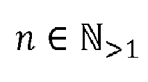
- the invention relates to a cable saddle for supporting cables in a cable loop of a wind turbine next to a free-hanging loop part of the cable loop, wherein the cable saddle n ⁇ N > 1 vertically superposed saddle surfaces, wherein at least one saddle surface has a width sufficient to support at least 1 / n of the cables and all saddle surfaces are dimensioned together to support the cables thereon without overlapping or contacting any two adjacent cables ,
- the invention relates to a wind turbine comprising a tower, a nacelle arranged on the top of the tower such that the nacelle can pivot in the azimuth direction, and a plurality of cables which are guided by a cable loop from the tower into the nacelle, where the cables are supported by a cable saddle mounted in the tower adjacent to the free-hanging loop portion of the cable loop, the cable saddle being designed according to the invention.
- the invention is based on the recognition that a support surface for the free-hanging loop part of the cable loop, which is separated into vertically stacked parts, compared to a one-piece, continuous support surface according to the prior art has several advantages.
- a support surface for the free-hanging loop part of the cable loop which is separated into vertically stacked parts, compared to a one-piece, continuous support surface according to the prior art has several advantages.
- a lighter structure can be achieved.
- the maximum transverse displacement of the outermost cables in the free-hanging loop can be significantly reduced, which reduces the torsional stress of selbiger cable.
- the cable saddle according to the invention still provides support of all cables without them interacting directly with each other, thus avoiding unnecessary wear and tear due to chafing and twisting.
- the number of vertically arranged saddle surfaces is unlimited. However, in most cases, with a manageable number of cables to support (eg, 20 to 30 cables), two cable saddles already provide all the advantages of the invention while keeping the cable saddle structure simple and cost efficient. Thus, it is preferred that the number of cable saddles is n 2 (ie, n 2).
- the cross section of at least one saddle surface comprises a circle section, the convex side forming at least part of the cable support surface.
- the saddle surfaces have the same width and / or the same cross-section. This allows the elements forming the saddle surfaces to be identical to each other, which simplifies their manufacture. If the saddle surfaces have the same width, the cables can be evenly distributed over all saddle surfaces.
- the saddle surfaces can be mounted on a common frame, which fixes the saddle surfaces in their relative position and allows joint mounting of the saddle surfaces. This allows easy installation of the cable saddle in place within the tower.
- the common frame may also include end members or portions that abut and extend beyond the saddle surfaces to prevent cables from slipping off either of the two saddle surfaces.
- the saddle surfaces are provided with a plurality of mounting slots for receiving fixation means, preferably cable ties, for individually fixing cables to the cable surfaces.
- fixation means preferably cable ties
- the cable saddle comprises a non-rotatable but vertically movable holding device to which the cables can be rigidly attached at the other end of the free-hanging loop part.
- the holding device can be connected directly to the cable saddle, z. B. articulated, and thus form an integral part of the latter.
- the holding device is designed as a separate element which is to be mounted individually in the tower of a wind turbine and yet forms a functional part of the cable saddle.
- the holding device comprises on the side facing the free-hanging loop part of the cable loop at least one linear row of cable holders, wherein preferably the axis of the at least one linear row is parallel to the width of the saddle surfaces of the cable saddle.
- the number of linear rows of cable holders is equal to the number of vertically arranged saddle surfaces of the cable saddle.
- the saddle surface, the common frame, the end elements or sections and / or the holding device are preferably made at least partially of steel, preferably of S 235 JR.
- the wind turbine according to the invention is characterized mainly by the use of the cable saddle according to the invention. For details, reference is thus made to above.
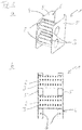
- FIG. 1 a first embodiment of a cable saddle 1 according to the invention is shown in two views. The actual use of the cable saddle 1 is in FIG. 2 displayed.
- the cable saddle 1 is intended to support the cables in a cable loop of a wind turbine next to the free-hanging loop part 31 of the cable loop 30.
- the cable saddle 1 comprises two vertically arranged saddle surfaces 2.
- the saddle surfaces 2 both have an identical width and an identical cross-section in order to simplify a cost-effective production.
- both saddle surfaces 2 consists of a circular section whose convex side forms the actual surface from which the cables 10 are supported.
- the radius of the circular section is chosen such that the cables 10 supported thereon do not bend beyond their respective maximum curvature.
- the width of the two saddle surfaces 2 is chosen so that it can support half of the total number of cables 10 of the cable loop (in this example: a total of 22 cables, ie 11 cables each) sufficiently spaced therefrom, so that no overlap and no contact between two any adjacent cables 10 consists.
- the saddle surfaces 2 are provided with a plurality of mounting slots 3. Cable ties (not shown) may interlock with these mounting slots 3 to individually secure the cables 10 to the saddle surfaces 2 in the desired spaced locations.
- the two saddle surfaces 2 are mounted on a common frame 4 which comprises two end elements 5.
- the two end elements 5 hold the saddle surface 2 in their respective relative position and allow the mounting of the cable saddle 2 on the inner wall of a tower 20 of a wind turbine (of which only a part in FIG. 2b is indicated) by means of fastening holes 6.
- the end elements 5 are designed to be adjacent to the saddle surfaces 2 and project beyond them. In this way, even without the use of cable ties, the cables 10 can not slip from one of the two saddle surfaces 2.
- the free-hanging loop 31 of the cable loop 30 can be arranged by a suitable choice of the length of the cable 10 such that a collision between cables 10, which end on two different saddle surfaces 2 of the cable saddle 1, is avoided.
- FIG. 3 shows a second embodiment of a cable saddle 1 according to the present invention.
- the part of the cable saddle 1, which includes the actual cable surfaces 2, which are mounted on the common frame 4, is with the in the FIGS. 1 and 2 shown cable saddle 1 identical. Thus, for a detailed explanation of this part, see above.
- the in FIG. 3 shown cable saddle 1 further comprises a rotationally fixed, but vertically movable holding device 7, to which the cable 10 at the end of the free-hanging loop member 31 which is not supported by the saddle surfaces 2, can be rigidly attached.
- this holding device 7 With this holding device 7, the twisting of the cable 10 due to the pivoting of the nacelle (not shown) is kept away from the free-hanging loop member 31 of the cable loop 30 in a basically known manner.
- the vertical movement of the holding device 7 is achieved by a hinged mounting of the device 7 on the common frame 4.
- the holding device 7 on the free-hanging loop part 31 of the cable loop 30 side facing comprises two linear rows 8 of cable holders 9, wherein the individual axis of both linear rows to the width of the saddle surfaces 2 of the cable saddle 1 is parallel. With these cable holders 9, a course of the cable 10 as in FIG. 2b can be achieved permanently.
Landscapes
- Engineering & Computer Science (AREA)
- Life Sciences & Earth Sciences (AREA)
- Sustainable Development (AREA)
- Sustainable Energy (AREA)
- Chemical & Material Sciences (AREA)
- Combustion & Propulsion (AREA)
- Mechanical Engineering (AREA)
- General Engineering & Computer Science (AREA)
- Wind Motors (AREA)
Abstract

Description
- Die Erfindung betrifft Kabelsattel zum Stützen von Kabeln in einer Kabelschlaufe einer Windkraftanlage und entsprechende Kabelsattel umfassende Windkraftanlagen.
- Moderne Windkraftanlagen verfügen üblicherweise über eine horizontale Rotorachse, die eine Ausrichtung zum Wind erfordert. Dies wird durch ein Schwenken der die Rotorachse haltenden Gondel bezogen auf den stationären Turm in Azimutrichtung erreicht, um der Windrichtung zu folgen. Während des Betriebs wird die Gondel in einer zufällig verteilten Abfolge, die der stochastischen Windrichtungsverteilung entspricht, geschwenkt. Die elektrische Übertragung von der den Stromgenerator enthaltenden Gondel muss die konstante Relativbewegung zwischen der Gondel und dem Turm mit seiner stationären Verkabelung ausgleichen.
- Für diesen Ausgleich sind sogenannte Kabelschlaufen, bei denen die Kabel in einer hängenden Schlaufe von der Gondel in den Turm geführt werden, weit verbreitet. Die Kabelschlaufe erlaubt gewöhnlich zwei oder drei vollständige Umdrehungen der Gondel, was sich in den meisten Fällen, zumindest dann, wenn die Steuerungseinrichtung der Windkraftanlage ein Notfallprogramm zum Entwirren der Kabelschlaufe bei drohender Überbeanspruchung umfasst, als ausreichend erwiesen hat.
-
WO 2010/105852 A2 hat eine Weiterentwicklung der Kabelschlaufe dahingehend, dass die Kabelschlaufe durch einen drehfesten, aber vertikal bewegbaren Führungsring in zwei Abschnitte, einen lediglich verdrehbaren Abschnitt und einen gekrümmten Längenausgleichsabschnitt, geteilt ist, beschrieben. Bei Letzterer werden durch die Schwenkbewegung der Gondel in keinster Weise verdreht. - Unabhängig davon, ob ein Führungsring vorhanden ist, umfasst die Kabelschlaufe an ihrem unteren Ende einen freihängenden Schlingenteil, dessen turmnahes Ende in der Regel über ein Richtungswechselelement geführt wird. Diese Richtungselemente umfassen eine horizontale Stütze, über welche die Kabel von der Kabelschlaufe locker gehängt werden. Damit nebeneinander liegende Kabel in der Nähe des Richtungswechselelements nicht miteinander in Kontakt stehen, um ein Aneinanderscheuern zu vermeiden, erfordert die horizontale Stütze oft eine erhebliche Breite und somit ein hohes Gewicht der ausreichend stabilen Struktur.
- Alternativ hierzu können die Kabel in ein einziges Richtungswechselelement gezwängt werden, so dass sie wenigstens teilweise über einander liegen. In diesem Fall interagieren die Kabel jedoch ständig (z. B. durch Scheuern aneinander oder miteinander Verdrehen), was zu erhöhtem Verschleiß und erhöhter Abnutzung führt. Weiterhin ist, da Kabel sich umeinander verdrehen können, ein zusätzlicher Sicherheitsspielraum für die Längen der Kabel erforderlich, um eine Verkürzung aufgrund von Verdrehen ausgleichen zu können.
- Es ist Aufgabe der vorliegenden Erfindung, Mittel für eine verbesserte Kabelschlaufe einer Windkraftanlage bereitzustellen, die nicht die aus dem Stand der Technik bekannten Nachteile aufweist.
- Die Lösung nach der Erfindung liegt im Kabelsattel nach dem Hauptanspruch und der Windkraftanlage nach dem nebengeordneten Anspruch 12. Vorteilhafte Erweiterungen bilden den Gegenstand der Unteransprüche.
- Somit betrifft die Erfindung einen Kabelsattel zum Stützen von Kabeln in einer Kabelschlaufe einer Windkraftanlage neben einem freihängenden Schlingenteil der Kabelschlaufe, wobei der Kabelsattel
- Weiterhin betrifft die Erfindung eine Windkraftanlage, die einen Turm, eine auf der Spitze des Turms derart angeordnete Gondel, dass die Gondel in der Azimutrichtung schwenken kann, und eine Mehrzahl an Kabeln, die mittels einer Kabelschlaufe vom Turm in die Gondel geführt werden, umfasst, wo die Kabel von einem Kabelsattel, der im Turm neben dem freihängenden Schlingenteil der Kabelschlaufe montiert ist, gestützt werden, wobei der Kabelsattel nach der Erfindung ausgelegt ist.
- Die Erfindung basiert auf der Erkenntnis, dass eine Stützoberfläche für den freihängenden Schlingenteil der Kabelschlaufe, die in vertikal übereinander angeordnete Teile getrennt ist, gegenüber einer einstückigen, durchgängigen Stützfläche nach dem Stand der Technik mehrere Vorteile aufweist. Im Vergleich des Kabelsattels nach der Erfindung mit einem herkömmlichen Kabelsattel mit einer einstückigen Stützoberfläche von ausreichender Breite zum Stützen aller Kabel, ohne dass diese in Kontakt zueinander stehen, kann eine leichtere Struktur erreicht werden. Weiterhin kann die maximale Querverlagerung der äußersten Kabel in der freihängenden Schlinge erheblich reduziert werden, was die Torsionsbeanspruchung selbiger Kabel reduziert. Dennoch erreicht der Kabelsattel nach der Erfindung nach wie vor eine Stützung aller Kabel, ohne das diese direkt miteinander interagieren, und vermeidet somit unnötige Abnutzung und Verschleiß aufgrund von Scheuern und Verdrehen. Generell ist die Anzahl an vertikal aufeinander angeordneten Sattelflächen unbegrenzt. In den meisten Fällen mit einer überschaubaren Anzahl an zu stützenden Kabeln (z. B. 20 bis 30 Kabel) bieten jedoch bereits zwei Kabelsattel alle Vorteile der Erfindung und halten gleichzeitig die Kabelsattelstruktur einfach und kosteneffizient. Somit ist bevorzugt, dass die Anzahl an Kabelsatteln n 2 ist (d. h. n 2).
- Es ist bevorzugt, dass der Querschnitt von wenigstens einer Sattelfläche einen Kreisabschnitt umfasst, wobei die konvexe Seite wenigstens einen Teil der Kabelstützfläche bildet. Durch Zurückgreifen auf Kreisabschnitte für die Kabelstützfläche kann das Risiko, dass die Kabel über ihre maximale Krümmung hinaus gebogen werden, im Wesentlichen wenigstens in der Nähe des Kabelsattels eliminiert werden. Selbstverständlich muss der Radius der Kreisabschnitte für die Kabelstützflächen an die entsprechenden Kabeleigenschaften angepasst werden.
- Vorzugsweise weisen die Sattelflächen dieselbe Breite und/oder denselben Querschnitt auf. Dies ermöglicht, dass die die Sattelflächen bildenden Elemente zueinander identisch sind, was deren Herstellung vereinfacht. Wenn die Sattelflächen dieselbe Breite aufweisen, können die Kabel über alle Sattelflächen gleichmäßig verteilt sein.
- Die Sattelflächen können an einem gemeinsamen Rahmen montiert sein, der die Sattelflächen in ihrer Relativposition fixiert und eine gemeinschaftliche Montage der Sattelflächen ermöglicht. Dies ermöglicht eine einfache Installation des Kabelsattels vor Ort innerhalb des Turms. Der gemeinsame Rahmen kann zudem Abschlusselemente oder -abschnitte umfassen, die an die Sattelflächen angrenzen und über diese hinausragen, um zu verhindern, dass Kabel von einer der beiden Sattelflächen abrutschen.
- Es ist bevorzugt, dass die Sattelflächen mit einer Mehrzahl an Montageschlitzen versehen sind, um Fixierungsmittel, vorzugsweise Kabelbinder, aufzunehmen, um Kabel einzeln an den Kabelflächen zu fixieren. Auf diese Weise kann das Risiko, dass Kabel in der freihängenden Schlinge der Kabelschlaufe miteinander interagieren, dauerhaft dadurch eliminiert werden, dass sie ausreichend beabstandet befestigt werden.
- Es ist bevorzugt, dass der Kabelsattel eine drehfeste, aber vertikal bewegbare Haltevorrichtung umfasst, an der die Kabel am anderen Ende des freihängenden Schlingenteils starr angebracht werden können. Auf diese Weise kann das Verdrehen von Kabeln aufgrund des Schwenkens der Gondel von dem freihängenden Schlingenteil der Kabelschlaufe ferngehalten werden. Die Haltevorrichtung kann mit dem Kabelsattel direkt verbunden, z. B. angelenkt, sein und somit einen integralen Bestandteil von letzterem bilden. Außerdem ist es möglich, dass die Haltevorrichtung als separates Element, das im Turm einer Windkraftanlage individuell zu montieren ist und dennoch einen funktionalen Bestandteil des Kabelsattels bildet, ausgelegt ist.
- Vorzugsweise umfasst die Haltevorrichtung an der dem freihängenden Schlingenteil der Kabelschlaufe zugewandten Seite wenigstens eine lineare Reihe von Kabelhaltern, wobei vorzugsweise die Achse der wenigstens einen linearen Reihe zu der Breite der Sattelflächen des Kabelsattels parallel ist. Weiterhin ist bevorzugt, dass die Anzahl an linearen Reihen von Kabelhaltern der Anzahl an vertikal aufeinander angeordneten Sattelflächen des Kabelsattels gleich ist. Durch Bereitstellen von einer oder mehreren Reihen von Kabelhaltern kann der Verlauf der einzelnen Kabel in dem freihängenden Schlingenteil der Kabelschlaufe für alle vertikalen Positionen der Haltevorrichtung ziemlich genau definiert werden.
- Die Sattelfläche, der gemeinsame Rahmen, die Abschlusselemente oder -abschnitte und/oder die Haltevorrichtung sind vorzugsweise wenigstens teilweise aus Stahl, vorzugsweise aus S 235 JR, hergestellt.
- Die erfindungsgemäße Windkraftanlage ist hauptsächlich durch die Verwendung des erfindungsgemäßen Kabelsattels gekennzeichnet. Für Details wird somit auf oben verwiesen.
- Figuren genauer beschrieben:
- Figur 1a, b:
- schematische Darstellung einer ersten Ausführungsform eines Kabelsattels nach der Erfindung;
- Figur 2a, b:
- schematische Darstellung des Kabelsattels nach
Figur 1 in Verwendung; und - Figur 3:
- schematische Darstellung einer zweiten Ausführungsform eines Kabelsattels nach der Erfindung.
- In
Figur 1 ist eine erste Ausführungsform eines Kabelsattels 1 nach der Erfindung in zwei Ansichten dargestellt. Die tatsächliche Verwendung des Kabelsattels 1 ist inFigur 2 abgebildet. - Der Kabelsattel 1 soll die Kabel in einer Kabelschlaufe einer Windkraftanlage neben dem freihängenden Schlingenteil 31 der Kabelschlaufe 30 stützen. Dafür umfasst der Kabelsattel 1 zwei vertikal aufeinander angeordnete Sattelflächen 2. Die Sattelflächen 2 weisen beide eine identische Breite und einen identischen Querschnitt auf, um eine kosteneffiziente Herstellung zu vereinfachen.
- Der Querschnitt beider Sattelflächen 2 besteht aus einem Kreisabschnitt, dessen konvexe Seite die tatsächliche Oberfläche, von der die Kabel 10 gestützt werden, bildet. Der Radius des Kreisabschnitts ist derart gewählt, dass die darauf gestützten Kabel 10 sich nicht über ihre jeweilige maximale Krümmung biegen. Die Breite der beiden Sattelflächen 2 ist derart gewählt, dass sie die Hälfte der Gesamtanzahl an Kabeln 10 der Kabelschlaufe (in diesem Beispiel: insgesamt 22 Kabel, d. h. jeweils 11 Kabel) darauf ausreichend beabstandet stützen kann, so dass keine Überlappung und kein Kontakt zwischen zwei beliebigen nebeneinander liegenden Kabeln 10 besteht.
- Die Sattelflächen 2 werden mit einer Mehrzahl an Montageschlitzen 3 bereitgestellt. Mit diesen Montageschlitzen 3 können Kabelbinder (nicht dargestellt) ineinandergreifen, um die Kabel 10 in den gewünschten beabstandeten Positionen an den Sattelflächen 2 individuell zu befestigen.
- Wie aus den Figuren leicht erkennbar ist, sind die beiden Sattelflächen 2 an einem gemeinsamen Rahmen 4, der zwei Abschlusselemente 5 umfasst, montiert. Die beiden Abschlusselemente 5 halten die Sattelfläche 2 in ihrer jeweiligen Relativposition und ermöglichen das Montieren des Kabelsattels 2 an der Innenwand eines Turms 20 einer Windkraftanlage (von welcher nur ein Teil in
Figur 2b angedeutet ist) mittels Befestigungslöchern 6. Weiterhin sind die Abschlusselemente 5 dazu ausgelegt, an die Sattelflächen 2 anzugrenzen und über diese hinauszuragen. Auf diese Weise können selbst ohne Verwendung von Kabelbindern die Kabel 10 nicht von einer der beiden Sattelflächen 2 rutschen. - Wie in
Figur 2b zu sehen ist, kann die freihängende Schlinge 31 der Kabelschlaufe 30 durch eine geeignete Wahl der Länge der Kabel 10 derart angeordnet werden, dass ein Zusammenstoßen zwischen Kabeln 10, die auf zwei unterschiedlichen Sattelflächen 2 des Kabelsattels 1 enden, vermieden wird. -
Figur 3 zeigt eine zweite Ausführungsform eines Kabelsattels 1 nach der vorliegenden Erfindung. Der Teil des Kabelsattels 1, der die tatsächlichen Kabelflächen 2, die am gemeinsamen Rahmen 4 montiert sind, umfasst, ist mit dem in denFiguren 1 und2 gezeigten Kabelsattel 1 identisch. Somit wird für eine ausführliche Erklärung dieses Teils auf oben verwiesen. - Der in
Figur 3 gezeigte Kabelsattel 1 umfasst weiterhin eine drehfeste, aber vertikal bewegbare Haltevorrichtung 7, an der die Kabel 10 am Ende des freihängenden Schlingenteils 31, der nicht von den Sattelflächen 2 gestützt wird, starr angebracht werden können. Mit dieser Haltevorrichtung 7 wird das Verdrehen der Kabel 10 aufgrund des Schwenkens der Gondel (nicht dargestellt) vom freihängenden Schlingenteil 31 der Kabelschlaufe 30 in einer grundsätzlich bekannten Weise ferngehalten. Die vertikale Bewegung der Haltevorrichtung 7 wird durch eine angelenkte Montage der Vorrichtung 7 am gemeinsamen Rahmen 4 erreicht. - Die Haltevorrichtung 7 an der dem freihängenden Schlingenteil 31 der Kabelschlaufe 30 zugewandten Seite umfasst zwei lineare Reihen 8 von Kabelhaltern 9, wobei die individuelle Achse beider linearer Reihen zu der Breite der Sattelflächen 2 des Kabelsattels 1 parallel ist. Mit diesen Kabelhaltern 9 kann ein Verlauf der Kabel 10 wie in
Figur 2b dargestellt dauerhaft erreicht werden. - Die in den Figuren dargestellten Ausführungsformen sind aus Stahl der Klasse S 235 JR hergestellt.
Claims (12)
- Kabelsattel (1) zum Stützen von Kabeln (10) in einer Kabelschlaufe (30) einer Windkraftanlage neben dem freihängenden Schlingenteil (31) der Kabelschlaufe (30), dadurch gekennzeichnet, dass der Kabelsattel (1)

- Kabelsattel nach Anspruch 1, wobei n = 2.
- Kabelsattel nach einem beliebigen der vorstehenden Ansprüche, wobei der Querschnitt von wenigstens einer Sattelfläche (2) einen Kreisabschnitt umfasst, wobei die konvexe Seite wenigstens einen Teil der Kabelstützfläche bildet.
- Kabelsattel nach einem beliebigen der vorstehenden Ansprüche, wobei die Sattelflächen (2) dieselbe Breite und/oder denselben Querschnitt aufweisen.
- Kabelsattel nach einem beliebigen der vorstehenden Ansprüche, wobei die Sattelflächen (2) an einem gemeinsamen Rahmen (4) montiert sind, der die Sattelflächen (2) in ihrer relativen Position fixiert und eine gemeinschaftliche Montage der Sattelflächen (2) ermöglicht.
- Kabelsattel nach den vorstehenden Ansprüchen, wobei der gemeinsame Rahmen (4) Abschlusselemente (5) oder -abschnitte umfasst, die an die Sattelflächen (2) angrenzen und über diese herausragen, um zu verhindern, dass Kabel (10) von einer der beiden Sattelflächen (2) rutschen.
- Kabelsattel nach einem beliebigen der vorstehenden Ansprüche, wobei die Sattelflächen (2) mit einer Mehrzahl an Montageschlitzen (3) versehen sind, um Fixierungsmittel, vorzugsweise Kabelbinder, aufzunehmen, um Kabel (10) individuell an den Sattelflächen (2) zu fixieren.
- Kabelsattel nach einem beliebigen der vorstehenden Ansprüche, wobei der Kabelsattel (1) eine drehfeste, aber vertikal bewegbare Haltevorrichtung (7) umfasst, an welcher die Kabel (10) am anderen Ende des freihängenden Schlingenteils (31) der Kabelschlaufe (30) starr angebracht sein können.
- Kabelsattel nach den vorstehenden Ansprüchen, wobei die Haltevorrichtung (7) an der dem freihängenden Schlingenteil (31) der Kabelschlaufe (30) zugewandten Seite wenigstens eine lineare Reihe (8) von Kabelhaltern (9) umfasst, wobei vorzugsweise die Achse der wenigstens einen linearen Reihe (8) zu der Breite der Sattelflächen (2) des Kabelsattels (1) parallel ist.
- Kabelsattel nach den vorstehenden Ansprüchen, wobei die Anzahl an linearen Reihen(8) von Kabelhaltern (9) der Anzahl an vertikal übereinander angeordneten Sattelflächen (2) des Kabelsattels (1) gleich ist.
- Kabelsattel nach einem beliebigen der vorstehenden Ansprüche, wobei die Sattelfläche (3), der gemeinsame Rahmen (4), die Abschlusselemente (5) oder -abschnitte und/oder die Haltevorrichtung (7) wenigstens teilweise aus Stahl, vorzugsweise aus S 235 JR, hergestellt sind.
- Windkraftanlage, die einen Turm (20), eine auf der Spitze des Turms (20) derart angeordnete Gondel, dass die Gondel in der Azimutrichtung schwenken kann, und eine Mehrzahl an Kabeln (10), die mittels einer Kabelschlaufe (30) vom Turm in die Gondel geführt werden, umfasst, wo die Kabel (10) von einem Kabelsattel (1), der im Turm (20) neben dem freihängenden Schlingenteil (31) der Kabelschlaufe (30) montiert ist, gestützt werden, dadurch gekennzeichnet, dass der Kabelsattel (1) nach einem beliebigen der vorstehenden Ansprüche ausgelegt ist.
Applications Claiming Priority (1)
| Application Number | Priority Date | Filing Date | Title |
|---|---|---|---|
| DE102017008893.4A DE102017008893A1 (de) | 2017-09-22 | 2017-09-22 | Kabelsattel zum Stützen von Kabeln in einer Kabelschlaufe einer Windkraftanlage |
Publications (2)
| Publication Number | Publication Date |
|---|---|
| EP3460239A1 true EP3460239A1 (de) | 2019-03-27 |
| EP3460239B1 EP3460239B1 (de) | 2021-06-16 |
Family
ID=63642782
Family Applications (1)
| Application Number | Title | Priority Date | Filing Date |
|---|---|---|---|
| EP18195320.9A Active EP3460239B1 (de) | 2017-09-22 | 2018-09-19 | Kabelsattel zum stützen von kabeln in einer kabelschlaufe einer windkraftanlage |
Country Status (2)
| Country | Link |
|---|---|
| EP (1) | EP3460239B1 (de) |
| DE (1) | DE102017008893A1 (de) |
Citations (4)
| Publication number | Priority date | Publication date | Assignee | Title |
|---|---|---|---|---|
| WO2010105852A2 (de) | 2009-03-20 | 2010-09-23 | Repower Systems Ag | Windenergieanlage mit verdrillbarer gondel-kabelführung |
| US20120133144A1 (en) * | 2011-11-28 | 2012-05-31 | Werner Barton | Unit for cable management and wind turbine |
| EP2495439A1 (de) * | 2009-10-27 | 2012-09-05 | Sinovel Wind Group Co., Ltd | Turmdrehkörper zur wind-elektrostromerzeugung |
| CN103362749B (zh) * | 2012-03-28 | 2015-09-16 | 华锐风电科技(集团)股份有限公司 | 一种风力发电机 |
-
2017
- 2017-09-22 DE DE102017008893.4A patent/DE102017008893A1/de not_active Withdrawn
-
2018
- 2018-09-19 EP EP18195320.9A patent/EP3460239B1/de active Active
Patent Citations (4)
| Publication number | Priority date | Publication date | Assignee | Title |
|---|---|---|---|---|
| WO2010105852A2 (de) | 2009-03-20 | 2010-09-23 | Repower Systems Ag | Windenergieanlage mit verdrillbarer gondel-kabelführung |
| EP2495439A1 (de) * | 2009-10-27 | 2012-09-05 | Sinovel Wind Group Co., Ltd | Turmdrehkörper zur wind-elektrostromerzeugung |
| US20120133144A1 (en) * | 2011-11-28 | 2012-05-31 | Werner Barton | Unit for cable management and wind turbine |
| CN103362749B (zh) * | 2012-03-28 | 2015-09-16 | 华锐风电科技(集团)股份有限公司 | 一种风力发电机 |
Also Published As
| Publication number | Publication date |
|---|---|
| EP3460239B1 (de) | 2021-06-16 |
| DE102017008893A1 (de) | 2019-03-28 |
Similar Documents
| Publication | Publication Date | Title |
|---|---|---|
| EP2577058B1 (de) | Turm für eine windturbine | |
| EP2409031B1 (de) | Windenergieanlage mit verdrillbarer gondel-kabelführung | |
| EP2789561A1 (de) | Aufzug | |
| DE2260301B2 (de) | Anordnung zur Überlastkontrolle von Verzurr- und/oder Anschlagketten | |
| EP2762723B1 (de) | Windenergieanlage mit Turm und Kabeln im Turm | |
| EP2812599A2 (de) | Energieführungsvorrichtung für grosse verdrehwinkel | |
| DE3715118C2 (de) | ||
| EP3460239B1 (de) | Kabelsattel zum stützen von kabeln in einer kabelschlaufe einer windkraftanlage | |
| EP3319898B1 (de) | Turmkran | |
| EP3857681B1 (de) | Rotor für eine elektrische maschine | |
| EP3658770B1 (de) | Windenergieanlagen-stahlturmringsegment und verfahren | |
| DE102017214152B3 (de) | Einrichtung einer Windenergieanlage zur elektrischen Verbindung einer drehbar gelagerten Einheit mit nach unten geführten Leitungen | |
| DE3126181A1 (de) | Abstandshalter und daempfer fuer die kabel von ueberland-hochspannungs-leitungen | |
| DE102022128717B4 (de) | Höhensicherungsvorrichtung zum einfachen an- und abkoppeln | |
| EP1985502A1 (de) | Kabelführung in einer Antriebseinheit eines deichselgelenkten Flurförderzeugs | |
| DE102008031181A1 (de) | Konsole | |
| EP3166808B1 (de) | Elektromechanischer stellantrieb | |
| WO2012025262A1 (de) | Kippbarer konverter mit pendelstabaufhängung | |
| DE102018208714A1 (de) | Kabelhalterung sowie ein Kabelführungssystem zum Einsatz in Fahrzeugen | |
| DE102007038567A1 (de) | Kabelführeinrichtung für Kabel- und Leitungsverbindungen an relativ zueinander drehbewegten Teilen von Geräten und Maschinen | |
| DE202020106401U1 (de) | Ausgabevorrichtung für eine flexible Leitungsanordnung und Leitungsführungseinrichtung mit Fördereinheit | |
| DE7811316U1 (de) | Vorrichtung zum Führen von Energieleitungen | |
| DE125382C (de) | ||
| DE69903946T2 (de) | Zwischenträger für eine langgestreckte sicherheitsleitung oder schiene | |
| DE1303181C2 (de) | Trag- und antriebsvorrichtung fuer das rohr eines drehrohrofens |
Legal Events
| Date | Code | Title | Description |
|---|---|---|---|
| PUAI | Public reference made under article 153(3) epc to a published international application that has entered the european phase |
Free format text: ORIGINAL CODE: 0009012 |
|
| STAA | Information on the status of an ep patent application or granted ep patent |
Free format text: STATUS: THE APPLICATION HAS BEEN PUBLISHED |
|
| AK | Designated contracting states |
Kind code of ref document: A1 Designated state(s): AL AT BE BG CH CY CZ DE DK EE ES FI FR GB GR HR HU IE IS IT LI LT LU LV MC MK MT NL NO PL PT RO RS SE SI SK SM TR |
|
| AX | Request for extension of the european patent |
Extension state: BA ME |
|
| STAA | Information on the status of an ep patent application or granted ep patent |
Free format text: STATUS: REQUEST FOR EXAMINATION WAS MADE |
|
| 17P | Request for examination filed |
Effective date: 20190927 |
|
| RBV | Designated contracting states (corrected) |
Designated state(s): AL AT BE BG CH CY CZ DE DK EE ES FI FR GB GR HR HU IE IS IT LI LT LU LV MC MK MT NL NO PL PT RO RS SE SI SK SM TR |
|
| RIC1 | Information provided on ipc code assigned before grant |
Ipc: F03D 80/80 20160101AFI20201202BHEP |
|
| GRAP | Despatch of communication of intention to grant a patent |
Free format text: ORIGINAL CODE: EPIDOSNIGR1 |
|
| STAA | Information on the status of an ep patent application or granted ep patent |
Free format text: STATUS: GRANT OF PATENT IS INTENDED |
|
| INTG | Intention to grant announced |
Effective date: 20210121 |
|
| RAP1 | Party data changed (applicant data changed or rights of an application transferred) |
Owner name: SIEMENS GAMESA RENEWABLE ENERGY SERVICE GMBH |
|
| GRAS | Grant fee paid |
Free format text: ORIGINAL CODE: EPIDOSNIGR3 |
|
| GRAA | (expected) grant |
Free format text: ORIGINAL CODE: 0009210 |
|
| STAA | Information on the status of an ep patent application or granted ep patent |
Free format text: STATUS: THE PATENT HAS BEEN GRANTED |
|
| AK | Designated contracting states |
Kind code of ref document: B1 Designated state(s): AL AT BE BG CH CY CZ DE DK EE ES FI FR GB GR HR HU IE IS IT LI LT LU LV MC MK MT NL NO PL PT RO RS SE SI SK SM TR |
|
| REG | Reference to a national code |
Ref country code: GB Ref legal event code: FG4D Free format text: NOT ENGLISH |
|
| REG | Reference to a national code |
Ref country code: CH Ref legal event code: EP |
|
| REG | Reference to a national code |
Ref country code: DE Ref legal event code: R096 Ref document number: 502018005720 Country of ref document: DE |
|
| REG | Reference to a national code |
Ref country code: AT Ref legal event code: REF Ref document number: 1402547 Country of ref document: AT Kind code of ref document: T Effective date: 20210715 |
|
| REG | Reference to a national code |
Ref country code: IE Ref legal event code: FG4D Free format text: LANGUAGE OF EP DOCUMENT: GERMAN |
|
| REG | Reference to a national code |
Ref country code: LT Ref legal event code: MG9D |
|
| PG25 | Lapsed in a contracting state [announced via postgrant information from national office to epo] |
Ref country code: HR Free format text: LAPSE BECAUSE OF FAILURE TO SUBMIT A TRANSLATION OF THE DESCRIPTION OR TO PAY THE FEE WITHIN THE PRESCRIBED TIME-LIMIT Effective date: 20210616 Ref country code: LT Free format text: LAPSE BECAUSE OF FAILURE TO SUBMIT A TRANSLATION OF THE DESCRIPTION OR TO PAY THE FEE WITHIN THE PRESCRIBED TIME-LIMIT Effective date: 20210616 Ref country code: FI Free format text: LAPSE BECAUSE OF FAILURE TO SUBMIT A TRANSLATION OF THE DESCRIPTION OR TO PAY THE FEE WITHIN THE PRESCRIBED TIME-LIMIT Effective date: 20210616 Ref country code: BG Free format text: LAPSE BECAUSE OF FAILURE TO SUBMIT A TRANSLATION OF THE DESCRIPTION OR TO PAY THE FEE WITHIN THE PRESCRIBED TIME-LIMIT Effective date: 20210916 |
|
| REG | Reference to a national code |
Ref country code: NL Ref legal event code: MP Effective date: 20210616 |
|
| PG25 | Lapsed in a contracting state [announced via postgrant information from national office to epo] |
Ref country code: GR Free format text: LAPSE BECAUSE OF FAILURE TO SUBMIT A TRANSLATION OF THE DESCRIPTION OR TO PAY THE FEE WITHIN THE PRESCRIBED TIME-LIMIT Effective date: 20210917 Ref country code: SE Free format text: LAPSE BECAUSE OF FAILURE TO SUBMIT A TRANSLATION OF THE DESCRIPTION OR TO PAY THE FEE WITHIN THE PRESCRIBED TIME-LIMIT Effective date: 20210616 Ref country code: RS Free format text: LAPSE BECAUSE OF FAILURE TO SUBMIT A TRANSLATION OF THE DESCRIPTION OR TO PAY THE FEE WITHIN THE PRESCRIBED TIME-LIMIT Effective date: 20210616 Ref country code: NO Free format text: LAPSE BECAUSE OF FAILURE TO SUBMIT A TRANSLATION OF THE DESCRIPTION OR TO PAY THE FEE WITHIN THE PRESCRIBED TIME-LIMIT Effective date: 20210916 Ref country code: LV Free format text: LAPSE BECAUSE OF FAILURE TO SUBMIT A TRANSLATION OF THE DESCRIPTION OR TO PAY THE FEE WITHIN THE PRESCRIBED TIME-LIMIT Effective date: 20210616 |
|
| PG25 | Lapsed in a contracting state [announced via postgrant information from national office to epo] |
Ref country code: EE Free format text: LAPSE BECAUSE OF FAILURE TO SUBMIT A TRANSLATION OF THE DESCRIPTION OR TO PAY THE FEE WITHIN THE PRESCRIBED TIME-LIMIT Effective date: 20210616 Ref country code: ES Free format text: LAPSE BECAUSE OF FAILURE TO SUBMIT A TRANSLATION OF THE DESCRIPTION OR TO PAY THE FEE WITHIN THE PRESCRIBED TIME-LIMIT Effective date: 20210616 Ref country code: SM Free format text: LAPSE BECAUSE OF FAILURE TO SUBMIT A TRANSLATION OF THE DESCRIPTION OR TO PAY THE FEE WITHIN THE PRESCRIBED TIME-LIMIT Effective date: 20210616 Ref country code: SK Free format text: LAPSE BECAUSE OF FAILURE TO SUBMIT A TRANSLATION OF THE DESCRIPTION OR TO PAY THE FEE WITHIN THE PRESCRIBED TIME-LIMIT Effective date: 20210616 Ref country code: CZ Free format text: LAPSE BECAUSE OF FAILURE TO SUBMIT A TRANSLATION OF THE DESCRIPTION OR TO PAY THE FEE WITHIN THE PRESCRIBED TIME-LIMIT Effective date: 20210616 Ref country code: RO Free format text: LAPSE BECAUSE OF FAILURE TO SUBMIT A TRANSLATION OF THE DESCRIPTION OR TO PAY THE FEE WITHIN THE PRESCRIBED TIME-LIMIT Effective date: 20210616 Ref country code: NL Free format text: LAPSE BECAUSE OF FAILURE TO SUBMIT A TRANSLATION OF THE DESCRIPTION OR TO PAY THE FEE WITHIN THE PRESCRIBED TIME-LIMIT Effective date: 20210616 Ref country code: PT Free format text: LAPSE BECAUSE OF FAILURE TO SUBMIT A TRANSLATION OF THE DESCRIPTION OR TO PAY THE FEE WITHIN THE PRESCRIBED TIME-LIMIT Effective date: 20211018 |
|
| PG25 | Lapsed in a contracting state [announced via postgrant information from national office to epo] |
Ref country code: PL Free format text: LAPSE BECAUSE OF FAILURE TO SUBMIT A TRANSLATION OF THE DESCRIPTION OR TO PAY THE FEE WITHIN THE PRESCRIBED TIME-LIMIT Effective date: 20210616 |
|
| RAP4 | Party data changed (patent owner data changed or rights of a patent transferred) |
Owner name: SIEMENS GAMESA RENEWABLE ENERGY SERVICE GMBH |
|
| REG | Reference to a national code |
Ref country code: DE Ref legal event code: R097 Ref document number: 502018005720 Country of ref document: DE |
|
| PLBE | No opposition filed within time limit |
Free format text: ORIGINAL CODE: 0009261 |
|
| STAA | Information on the status of an ep patent application or granted ep patent |
Free format text: STATUS: NO OPPOSITION FILED WITHIN TIME LIMIT |
|
| PG25 | Lapsed in a contracting state [announced via postgrant information from national office to epo] |
Ref country code: DK Free format text: LAPSE BECAUSE OF FAILURE TO SUBMIT A TRANSLATION OF THE DESCRIPTION OR TO PAY THE FEE WITHIN THE PRESCRIBED TIME-LIMIT Effective date: 20210616 |
|
| REG | Reference to a national code |
Ref country code: CH Ref legal event code: PL |
|
| REG | Reference to a national code |
Ref country code: BE Ref legal event code: MM Effective date: 20210930 |
|
| 26N | No opposition filed |
Effective date: 20220317 |
|
| PG25 | Lapsed in a contracting state [announced via postgrant information from national office to epo] |
Ref country code: MC Free format text: LAPSE BECAUSE OF FAILURE TO SUBMIT A TRANSLATION OF THE DESCRIPTION OR TO PAY THE FEE WITHIN THE PRESCRIBED TIME-LIMIT Effective date: 20210616 Ref country code: AL Free format text: LAPSE BECAUSE OF FAILURE TO SUBMIT A TRANSLATION OF THE DESCRIPTION OR TO PAY THE FEE WITHIN THE PRESCRIBED TIME-LIMIT Effective date: 20210616 |
|
| PG25 | Lapsed in a contracting state [announced via postgrant information from national office to epo] |
Ref country code: LU Free format text: LAPSE BECAUSE OF NON-PAYMENT OF DUE FEES Effective date: 20210919 Ref country code: IT Free format text: LAPSE BECAUSE OF FAILURE TO SUBMIT A TRANSLATION OF THE DESCRIPTION OR TO PAY THE FEE WITHIN THE PRESCRIBED TIME-LIMIT Effective date: 20210616 Ref country code: IE Free format text: LAPSE BECAUSE OF NON-PAYMENT OF DUE FEES Effective date: 20210919 Ref country code: BE Free format text: LAPSE BECAUSE OF NON-PAYMENT OF DUE FEES Effective date: 20210930 |
|
| PG25 | Lapsed in a contracting state [announced via postgrant information from national office to epo] |
Ref country code: LI Free format text: LAPSE BECAUSE OF NON-PAYMENT OF DUE FEES Effective date: 20210930 Ref country code: CH Free format text: LAPSE BECAUSE OF NON-PAYMENT OF DUE FEES Effective date: 20210930 |
|
| PG25 | Lapsed in a contracting state [announced via postgrant information from national office to epo] |
Ref country code: CY Free format text: LAPSE BECAUSE OF FAILURE TO SUBMIT A TRANSLATION OF THE DESCRIPTION OR TO PAY THE FEE WITHIN THE PRESCRIBED TIME-LIMIT Effective date: 20210616 |
|
| PG25 | Lapsed in a contracting state [announced via postgrant information from national office to epo] |
Ref country code: HU Free format text: LAPSE BECAUSE OF FAILURE TO SUBMIT A TRANSLATION OF THE DESCRIPTION OR TO PAY THE FEE WITHIN THE PRESCRIBED TIME-LIMIT; INVALID AB INITIO Effective date: 20180919 |
|
| PG25 | Lapsed in a contracting state [announced via postgrant information from national office to epo] |
Ref country code: MK Free format text: LAPSE BECAUSE OF FAILURE TO SUBMIT A TRANSLATION OF THE DESCRIPTION OR TO PAY THE FEE WITHIN THE PRESCRIBED TIME-LIMIT Effective date: 20210616 |
|
| PG25 | Lapsed in a contracting state [announced via postgrant information from national office to epo] |
Ref country code: MT Free format text: LAPSE BECAUSE OF FAILURE TO SUBMIT A TRANSLATION OF THE DESCRIPTION OR TO PAY THE FEE WITHIN THE PRESCRIBED TIME-LIMIT Effective date: 20210616 |
|
| PGFP | Annual fee paid to national office [announced via postgrant information from national office to epo] |
Ref country code: DE Payment date: 20240926 Year of fee payment: 7 |
|
| PGFP | Annual fee paid to national office [announced via postgrant information from national office to epo] |
Ref country code: GB Payment date: 20240924 Year of fee payment: 7 |
|
| PGFP | Annual fee paid to national office [announced via postgrant information from national office to epo] |
Ref country code: FR Payment date: 20240925 Year of fee payment: 7 |
|
| REG | Reference to a national code |
Ref country code: AT Ref legal event code: MM01 Ref document number: 1402547 Country of ref document: AT Kind code of ref document: T Effective date: 20230919 |
|
| PG25 | Lapsed in a contracting state [announced via postgrant information from national office to epo] |
Ref country code: AT Free format text: LAPSE BECAUSE OF NON-PAYMENT OF DUE FEES Effective date: 20230919 |
|
| PG25 | Lapsed in a contracting state [announced via postgrant information from national office to epo] |
Ref country code: AT Free format text: LAPSE BECAUSE OF NON-PAYMENT OF DUE FEES Effective date: 20230919 |
|
| PG25 | Lapsed in a contracting state [announced via postgrant information from national office to epo] |
Ref country code: TR Free format text: LAPSE BECAUSE OF FAILURE TO SUBMIT A TRANSLATION OF THE DESCRIPTION OR TO PAY THE FEE WITHIN THE PRESCRIBED TIME-LIMIT Effective date: 20210616 |
|
| PGFP | Annual fee paid to national office [announced via postgrant information from national office to epo] |
Ref country code: AT Payment date: 20260410 Year of fee payment: 5 |