EP3459765B1 - Lauffläche für einen reifen - Google Patents
Lauffläche für einen reifen Download PDFInfo
- Publication number
- EP3459765B1 EP3459765B1 EP18194473.7A EP18194473A EP3459765B1 EP 3459765 B1 EP3459765 B1 EP 3459765B1 EP 18194473 A EP18194473 A EP 18194473A EP 3459765 B1 EP3459765 B1 EP 3459765B1
- Authority
- EP
- European Patent Office
- Prior art keywords
- groove
- tire
- tread
- sidewalls
- rib
- Prior art date
- Legal status (The legal status is an assumption and is not a legal conclusion. Google has not performed a legal analysis and makes no representation as to the accuracy of the status listed.)
- Active
Links
Images

Classifications
-
- B—PERFORMING OPERATIONS; TRANSPORTING
- B60—VEHICLES IN GENERAL
- B60C—VEHICLE TYRES; TYRE INFLATION; TYRE CHANGING; CONNECTING VALVES TO INFLATABLE ELASTIC BODIES IN GENERAL; DEVICES OR ARRANGEMENTS RELATED TO TYRES
- B60C11/00—Tyre tread bands; Tread patterns; Anti-skid inserts
- B60C11/03—Tread patterns
- B60C11/13—Tread patterns characterised by the groove cross-section, e.g. for buttressing or preventing stone-trapping
-
- B—PERFORMING OPERATIONS; TRANSPORTING
- B60—VEHICLES IN GENERAL
- B60C—VEHICLE TYRES; TYRE INFLATION; TYRE CHANGING; CONNECTING VALVES TO INFLATABLE ELASTIC BODIES IN GENERAL; DEVICES OR ARRANGEMENTS RELATED TO TYRES
- B60C11/00—Tyre tread bands; Tread patterns; Anti-skid inserts
- B60C11/03—Tread patterns
- B60C11/0302—Tread patterns directional pattern, i.e. with main rolling direction
-
- B—PERFORMING OPERATIONS; TRANSPORTING
- B60—VEHICLES IN GENERAL
- B60C—VEHICLE TYRES; TYRE INFLATION; TYRE CHANGING; CONNECTING VALVES TO INFLATABLE ELASTIC BODIES IN GENERAL; DEVICES OR ARRANGEMENTS RELATED TO TYRES
- B60C11/00—Tyre tread bands; Tread patterns; Anti-skid inserts
- B60C11/03—Tread patterns
- B60C11/04—Tread patterns in which the raised area of the pattern consists only of continuous circumferential ribs, e.g. zig-zag
- B60C11/042—Tread patterns in which the raised area of the pattern consists only of continuous circumferential ribs, e.g. zig-zag further characterised by the groove cross-section
-
- B—PERFORMING OPERATIONS; TRANSPORTING
- B60—VEHICLES IN GENERAL
- B60C—VEHICLE TYRES; TYRE INFLATION; TYRE CHANGING; CONNECTING VALVES TO INFLATABLE ELASTIC BODIES IN GENERAL; DEVICES OR ARRANGEMENTS RELATED TO TYRES
- B60C11/00—Tyre tread bands; Tread patterns; Anti-skid inserts
- B60C11/03—Tread patterns
- B60C11/04—Tread patterns in which the raised area of the pattern consists only of continuous circumferential ribs, e.g. zig-zag
- B60C11/042—Tread patterns in which the raised area of the pattern consists only of continuous circumferential ribs, e.g. zig-zag further characterised by the groove cross-section
- B60C11/047—Tread patterns in which the raised area of the pattern consists only of continuous circumferential ribs, e.g. zig-zag further characterised by the groove cross-section the groove bottom comprising stone trapping protection elements, e.g. ribs
-
- B—PERFORMING OPERATIONS; TRANSPORTING
- B60—VEHICLES IN GENERAL
- B60C—VEHICLE TYRES; TYRE INFLATION; TYRE CHANGING; CONNECTING VALVES TO INFLATABLE ELASTIC BODIES IN GENERAL; DEVICES OR ARRANGEMENTS RELATED TO TYRES
- B60C11/00—Tyre tread bands; Tread patterns; Anti-skid inserts
- B60C11/03—Tread patterns
- B60C2011/0337—Tread patterns characterised by particular design features of the pattern
- B60C2011/0339—Grooves
- B60C2011/0341—Circumferential grooves
-
- B—PERFORMING OPERATIONS; TRANSPORTING
- B60—VEHICLES IN GENERAL
- B60C—VEHICLE TYRES; TYRE INFLATION; TYRE CHANGING; CONNECTING VALVES TO INFLATABLE ELASTIC BODIES IN GENERAL; DEVICES OR ARRANGEMENTS RELATED TO TYRES
- B60C11/00—Tyre tread bands; Tread patterns; Anti-skid inserts
- B60C11/03—Tread patterns
- B60C2011/0337—Tread patterns characterised by particular design features of the pattern
- B60C2011/0339—Grooves
- B60C2011/0341—Circumferential grooves
- B60C2011/0355—Circumferential grooves characterised by depth
-
- B—PERFORMING OPERATIONS; TRANSPORTING
- B60—VEHICLES IN GENERAL
- B60C—VEHICLE TYRES; TYRE INFLATION; TYRE CHANGING; CONNECTING VALVES TO INFLATABLE ELASTIC BODIES IN GENERAL; DEVICES OR ARRANGEMENTS RELATED TO TYRES
- B60C11/00—Tyre tread bands; Tread patterns; Anti-skid inserts
- B60C11/03—Tread patterns
- B60C11/13—Tread patterns characterised by the groove cross-section, e.g. for buttressing or preventing stone-trapping
- B60C11/1353—Tread patterns characterised by the groove cross-section, e.g. for buttressing or preventing stone-trapping with special features of the groove bottom
- B60C2011/1361—Tread patterns characterised by the groove cross-section, e.g. for buttressing or preventing stone-trapping with special features of the groove bottom with protrusions extending from the groove bottom
Definitions
- the present invention relates to a pneumatic tire with an improved tread, and more particularly, relates to a pneumatic tire tread having improved acoustic characteristics.
- pneumatic tire treads often have sipes on a tread surface in order to demonstrate favorable functional characteristics (e.g., low rolling resistance, good traction, good durability, etc.).
- JP02189204 discloses a tire with a reduced noise generation, wherein partition parts are provided in groove which have defined widths in relation to the width of the groove.
- US 2,260,193 discloses a tire comprising serpentine load support ribs comprising additional reinforcing ribs of less height than the load support ribs in adjacent grooves.
- US 2,197,662 discloses in an embodiment a tire having double ribs and in grooves between each pair of double ribs a fin 16 which helps to avoid stone getting stuck in the grooves between the pairs of ribs.
- JP2000177323 discloses a tire intended to improve wear resistance and in particular uneven wear resistance. For that purpose some ribs have slightly different radial height and special widths compared to neighboring ribs.
- US 2014/0116588 provides a special tread pattern for avoiding cracks in groove bottoms. This is amongst others achieved by specific radii of the tread rubber at the groove bottom corners and a defined heights of adjacent ribs.
- Axial and “Axially” means the lines or directions that are parallel to the axis of rotation of the tire.
- “Circumferential” means circular lines or directions extending along the perimeter of the surface of the annular tread perpendicular to the axial direction; it can also refer to the direction of the sets of adjacent circular curves whose radii define the axial curvature of the tread, as viewed in cross section.
- dBA means A-weighted decibels, abbreviated dBA, or dBa, or dB(a), which are an expression of the relative loudness of sounds in air as perceived by the human ear.
- dBA A-weighted decibels
- dBA or dBa, or dB(a)
- Directional Tread Pattern means a tread pattern designed for specific direction of rotation.
- Equatorial Plane means the plane perpendicular to the tire's axis of rotation and passing through the center of its tread; or the plane containing the circumferential centerline of the tread.
- “Groove” means an elongated void area in a tread that may extend circumferentially or laterally in the tread in a straight, curved or zigzag manner. It is understood that all groove widths are measured perpendicular to the centerline of the groove.
- Hertz means number of cycles per second.
- “Lateral” means a direction going from one sidewall of the tire towards the other sidewall of the tire.
- Net to gross means the ratio of the net ground contacting tread surface to the gross area of the tread including the ground contacting tread surface and void spaces comprising grooves, notches and sipes.
- Notch means a void area of limited length that may be used to modify the variation of net to gross void area at the edges of blocks.
- Ring and radially mean directions radially toward or away from the axis of rotation of the tire.
- Sipe means a groove having a width in the range of 0.2% to 0.8% of the axial tread width. Sipes are typically formed by steel blades having a 0.4 to 1.6 mm, inserted into a cast or machined mold.
- Tangential and “Tangentially” refer to segments of circular curves that intersect at a point through which can be drawn a single line that is mutually tangential to both circular segments.
- Thread means the ground contacting portion of a tire.
- TW Thread width
- Vehicle Space means areas of the tread surface comprising grooves, notches and sipes.
- the invention relates to a tread in accordance with claim 1 and to a tire in accordance with claim 10.
- the radial height of the first groove rib is one-half the radial height of the first circumferential groove.
- a fourth circumferential groove extends in a circumferential direction entirely encircling the tire, the fourth circumferential groove having two sidewalls extending radially outward from an annular base, each sidewall defining a plane perpendicular to a rotational axis of the tire; and a fourth groove rib projects radially outward from the annular base of the fourth circumferential groove, the fourth groove rib extending circumferentially and entirely encircling the tire, the fourth groove rib having two sidewalls extending radially outward from the annular base of the fourth circumferential groove to a radially outermost annular surface of the fourth groove rib, each sidewall of the fourth groove rib defining a plane perpendicular to a rotational axis of the tire, the sidewalls of the fourth circumferential groove extending circumferentially and parallel to the sidewalls of the fourth groove rib, the fourth groove rib having a radial height less than a radial
- the sidewalls of each of the first, second, third, and fourth groove ribs are parallel to each other.
- the sidewalls of each of the first, second, third, and fourth circumferential grooves are parallel to the sidewalls of the first groove rib.
- each of the sidewalls of the first circumferential groove is parallel to each of the sidewalls of the second groove rib.
- each of the sidewalls of the second circumferential groove is parallel to each of the sidewalls of the third groove rib.
- each of the sidewalls of the third circumferential groove is parallel to each of the sidewalls of the fourth groove rib.
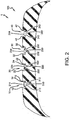
- a pneumatic tire 1 in accordance with an embodiment of the present invention includes a tread 100 with a first main circumferential groove 10, a second main circumferential groove 20, a third main circumferential groove 30, and a fourth main circumferential groove 40 all extending in a circumferential direction C of the pneumatic tire forming the tread 100.
- Five land portions, or ribs 110, 120, 130, 140, 150 are formed by these main circumferential grooves 10, 20, 30, 40.
- the main circumferential grooves 10, 20, 30, 40 preferably have a lateral width in a range of from 3.0 mm to 20.0 mm, more preferably 3mm to 10 mm, and preferably have a radial depth in a range of from 5.0 mm to 13.0 mm.
- the first circumferential groove 10 has two sidewalls 12 extending radially outward from an annular base 14. Each sidewall 12 thereby defines a plane perpendicular to a rotational axis 5 of the tire 1.
- Projecting radially outward from the base 14 of the groove 10 is a rectangular groove rib 210.
- the groove rib 210 has two sidewalls 212 extending radially outward from the base 14 to a radially outermost annular surface 214 of the groove rib.
- Each sidewall 212 thereby defines a plane perpendicular to a rotational axis 5 of the tire 1.
- the sidewalls 12 of the first circumferential groove 10 extend circumferentially and parallel to the sidewalls 212 of the groove rib 210.
- the sidewalls 212 of the groove rib 210 preferably have a radial height above the base 14 of about one-half a radial height of the sidewalls 12 of the first circumferential groove 10.
- the sidewalls 212 of the groove rib 210 preferably have a maximum radial height of from 2.5 mm to 4.0 mm.
- the radially outermost annular surface 214 of the first groove rib 210 forms a cylinder concentric with a cylinder formed by the annular base 14 of the first circumferential groove 10.
- the second circumferential groove 20 has two sidewalls 22 extending radially outward from an annular base 24. Each sidewall 22 thereby defines a plane perpendicular to a rotational axis 5 of the tire 1.
- Projecting radially outward from the base 24 of the groove 20 is a rectangular groove rib 220.
- the groove rib 220 has two sidewalls 222 extending radially outward from the base 24 to a radially outermost annular surface 224 of the groove rib.
- Each sidewall 222 thereby defines a plane perpendicular to a rotational axis 5 of the tire 1.
- the sidewalls 22 of the second circumferential groove 20 extend circumferentially and parallel to the sidewalls 212, 222 of the groove ribs 210, 220.
- the sidewalls 222 of the groove rib 220 preferably have a radial height above the base 24 of about one-half a radial height of the sidewalls 22 of the second circumferential groove 20.
- the sidewalls 222 of the groove rib 220 may have a maximum radial height of from 2.5 mm to 4.0 mm.
- the radially outermost annular surface 224 of the second groove rib 220 forms a cylinder concentric with the cylinders formed by the annular bases 14, 24 of the first and second circumferential groove 10, 20.
- the third circumferential groove 30 has two sidewalls 32 extending radially outward from an annular base 34. Each sidewall 32 thereby defines a plane perpendicular to a rotational axis 5 of the tire 1.
- Projecting radially outward from the base 34 of the groove 30 is a rectangular groove rib 230.
- the groove rib 230 has two sidewalls 232 extending radially outward from the base 34 to a radially outermost annular surface 234 of the groove rib.
- Each sidewall 232 thereby define a plane perpendicular to a rotational axis 5 of the tire 1.
- the sidewalls 32 of the third circumferential groove 30 extend circumferentially and parallel to the sidewalls 212, 222, 232 of the groove ribs 210, 220, 230.
- the sidewalls 232 of the groove rib 230 preferably have a radial height above the base 34 of about one-half a radial height of the sidewalls 32 of the third circumferential groove 30.
- the sidewalls 232 of the groove rib 230 may have a maximum radial height in a range of from 2.5 mm to 4.0 mm.
- the radially outermost annular surface 234 of the third groove rib 230 forms a cylinder concentric with the cylinders formed by the annular bases 14, 24, 34 of the first, second, and third circumferential grooves 10, 20, 30.
- the fourth circumferential groove 40 have two sidewalls 42 extending radially outward from an annular base 44. Each sidewall 42 thereby defines a plane perpendicular to a rotational axis 5 of the tire 1.
- Projecting radially outward from the base 44 of the groove 40 is a rectangular groove rib 240.
- the groove rib 240 has two sidewalls 242 extending radially outward from the base 44 to a radially outermost annular surface 244 of the groove rib. Each sidewall 242 thereby defines a plane perpendicular to a rotational axis 5 of the tire 1.
- the sidewalls 42 of the fourth circumferential groove 40 extend circumferentially and parallel to the sidewalls 212, 222, 232, 242 of the groove ribs 210, 220, 230, 240.
- the sidewalls 242 of the groove rib 240 have a radial height above the base 44 of preferably about one-half a radial height of the sidewalls 42 of the fourth circumferential groove 40.
- the sidewalls 242 of the groove rib 240 may have a maximum radial height in a range of from 2.5 mm to 4.0 mm.
- the radially outermost annular surface 244 of the fourth groove rib 240 forms a cylinder concentric with the cylinders formed by the annular bases 14, 24, 34, 44 of the first, second, third, and fourth circumferential grooves 10, 20, 30, 40.
- the groove ribs 210, 220, 230, 240 are disconnected from the sidewalls 12, 22, 32, 42 of the circumferential grooves 10, 20, 30, 40.
- the tread and tire in accordance with the invention reduces exterior noise under operating conditions of the tread 100 and tire 1 while having minimal effect on other functional characteristics of the tread and tire, such as cornering, braking, rolling resistance, wear, etc.
- the groove ribs 210, 220, 230, 240 in the circumferential grooves 10, 20, 30, 40 do not significantly alter the structural behavior of the tread 100 and tire 1, other than reduction of noise.
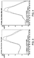
- Fig. 3 and Fig. 4 show this noise reduction through almost the entire test frequency range when adding the groove ribs 210, 220, 230, 240 to a tread pattern, such as the tread 100.
- the groove rib 240 Projecting radially outward from the base 44 of the groove 40 is a rectangular groove rib 240.
- the groove rib 240 has two sidewalls 242 extending radially outward from the base 44 to a radially outermost annular surface 244 of the groove rib. Each sidewall 242 thereby defines a plane perpendicular to a rotational axis 5 of the tire 1.
- the sidewalls 42 of the fourth circumferential groove 40 extend circumferentially and parallel to the sidewalls 212, 222, 232, 242 of the groove ribs 210, 220, 230, 240.
- the sidewalls 242 of the groove rib 240 have a radial height above the base 44 of preferably about one-half a radial height of the sidewalls 42 of the fourth circumferential groove 40.
- the sidewalls 242 of the groove rib 240 may have a maximum radial height in a range of from 2.5 mm to 4.0 mm.
- the radially outermost annular surface 244 of the fourth groove rib 240 forms a cylinder concentric with the cylinders formed by the annular bases 14, 24, 34, 44 of the first, second, third, and fourth circumferential grooves 10, 20, 30, 40.
- the groove ribs 210, 220, 230, 240 are disconnected from the sidewalls 12, 22, 32, 42 of the circumferential grooves 10, 20, 30, 40.
- the tread and tire in accordance with the invention reduces exterior noise under operating conditions of the tread 100 and tire 1 while having minimal effect on other functional characteristics of the tread and tire, such as cornering, braking, rolling resistance, wear, etc.
- the groove ribs 210, 220, 230, 240 in the circumferential grooves 10, 20, 30, 40 do not significantly alter the structural behavior of the tread 100 and tire 1, other than reduction of noise.
- Fig. 3 and Fig. 4 show this noise reduction through almost the entire test frequency range when adding the groove ribs 210, 220, 230, 240 to a tread pattern, such as the tread 100.
Landscapes
- Engineering & Computer Science (AREA)
- Mechanical Engineering (AREA)
- Tires In General (AREA)
Claims (10)
- Lauffläche für einen Reifen, wobei die Lauffläche Folgendes umfasst:eine erste zirkumferenzielle Rille (10), die sich in einer zirkumferenziellen Richtung zum vollständigen Umschließen des Reifens (1) erstreckt, wenn die Lauffläche (100) an einem Reifen (1) montiert ist, wobei die erste zirkumferenzielle Rille (10) zwei Seitenwände (12) aufweist, die sich von einer ringförmigen Basis (14) radial nach außen erstrecken, wobei jede Seitenwand (12) eine Ebene senkrecht zu einer Drehachse des Reifens (1) definiert, wenn die Lauffläche (100) an dem Reifen (1) montiert ist;eine erste Rillenrippe (210), die von der ringförmigen Basis (14) der ersten zirkumferenziellen Rille (10) radial nach außen vorsteht, wobei sich die erste Rillenrippe (210) zirkumferenziell erstreckt und den Reifen (1) vollständig umgibt, wenn die Lauffläche (100) an dem Reifen (1) montiert ist, wobei die erste Rillenrippe (210) zwei Seitenwände (212) aufweist, die sich von der ringförmigen Basis (14) der ersten zirkumferenziellen Rille (10) zu einer radial äußersten ringförmigen Oberfläche (214) der ersten Rillenrippe (210) radial nach außen erstrecken, wobei jede Seitenwand (212) der ersten Rillenrippe (210) eine Ebene senkrecht zu einer Drehachse (5) des Reifens (1) definiert, wenn die Lauffläche (100) an dem Reifen (1) montiert ist, wobei sich die Seitenwände (212) der ersten zirkumferenziellen Rille (10) zirkumferenziell und parallel zu den Seitenwänden (212) der ersten Rillenrippe (210) erstrecken, wobei die erste Rillenrippe (210) eine radiale Höhe, wie von der ringförmigen Basis (14) gemessen, von weniger als einer radialen Höhe der ersten zirkumferenziellen Rille (10) aufweist;eine zweite zirkumferenzielle Rille (20), die sich in einer zirkumferenziellen Richtung zum vollständigen Umschließen des Reifens (1) erstreckt, wenn die Lauffläche (100) an einem Reifen (1) montiert ist, wobei die zweite zirkumferenzielle Rille (20) zwei Seitenwände (22) aufweist, die sich von einer ringförmigen Basis (24) radial nach außen erstrecken, wobei jede Seitenwand (22) eine Ebene senkrecht zu einer Drehachse des Reifens (1) definiert, wenn die Lauffläche (100) an dem Reifen (1) montiert ist;eine zweite Rillenrippe (220), die von der ringförmigen Basis (24) der zweiten zirkumferenziellen Rille (20) radial nach außen vorsteht, wobei sich die zweite Rillenrippe (220) zirkumferenziell erstreckt und den Reifen (1) vollständig umgibt, wenn die Lauffläche (100) an dem Reifen (1) montiert ist, wobei die zweite Rillenrippe (220) zwei Seitenwände (222) aufweist, die sich von der ringförmigen Basis (24) der zweiten zirkumferenziellen Rille (20) zu einer radial äußersten ringförmigen Oberfläche (224) der zweiten Rillenrippe (220) radial nach außen erstrecken, wobei jede Seitenwand (222) der zweiten Rillenrippe (220) eine Ebene senkrecht zu einer Drehachse (5) des Reifens (1) definiert, wenn die Lauffläche (100) an dem Reifen (1) montiert ist, wobei sich die Seitenwände (222) der zweiten zirkumferenziellen Rille (20) zirkumferenziell und parallel zu den Seitenwänden (222) der zweiten Rillenrippe (220) erstrecken, wobei die zweite Rillenrippe (220) eine radiale Höhe, wie von der ringförmigen Basis (24) gemessen, von weniger als einer radialen Höhe der zweiten zirkumferenziellen Rille (20) aufweist;eine dritte zirkumferenzielle Rille (30), die sich in einer zirkumferenziellen Richtung zum vollständigen Umschließen des Reifens (1) erstreckt, wenn die Lauffläche (100) an einem Reifen (1) montiert ist, wobei die dritte zirkumferenzielle Rille (30) zwei Seitenwände (32) aufweist, die sich von einer ringförmigen Basis radial nach außen erstrecken, wobei jede Seitenwand (32) eine Ebene senkrecht zu einer Drehachse des Reifens (1) definiert, wenn die Lauffläche (100) an dem Reifen (1) montiert ist; undeine dritte Rillenrippe (230), die von der ringförmigen Basis der dritten zirkumferenziellen Rille (30) radial nach außen vorsteht, wobei sich die dritte Rillenrippe (230) zirkumferenziell erstreckt und den Reifen (1) vollständig umgibt, wenn die Lauffläche (100) an dem Reifen (1) montiert ist, wobei die dritte Rillenrippe (230) zwei Seitenwände (232) aufweist, die sich von der ringförmigen Basis der dritten zirkumferenziellen Rille (30) zu einer radial äußersten ringförmigen Oberfläche (234) der dritten Rillenrippe (230) radial nach außen erstrecken, wobei jede Seitenwand (232) der dritten Rillenrippe (230) eine Ebene senkrecht zu einer Drehachse (5) des Reifens (1) definiert, wenn die Lauffläche (100) an dem Reifen (1) montiert ist, wobei sich die Seitenwände (232) der dritten zirkumferenziellen Rille (30) zirkumferenziell und parallel zu den Seitenwänden (232) der dritten Rillenrippe (230) erstrecken, wobei die dritte Rillenrippe (230) eine radiale Höhe, wie von der ringförmigen Basis gemessen, von weniger als einer radialen Höhe der dritten zirkumferenziellen Rille (30) aufweist, dadurch gekennzeichnet, dasssich die erste, die zweite und die dritte zirkumferenzielle Rille (10, 20, 30) auf eine gerade Weise erstrecken und(i) die radiale Höhe der ersten Rillenrippe (210) in einem Bereich von 40 bis 60 Prozent der radialen Höhe der ersten zirkumferenziellen Rille (10) liegt;(ii) die radiale Höhe der zweiten Rillenrippe (220) in einem Bereich von 40 bis 60 Prozent der radialen Höhe der zweiten zirkumferenziellen Rille (20) liegt; und(iii) die radiale Höhe der dritten Rillenrippe (230) in einem Bereich von 40 bis 60 Prozent der radialen Höhe der dritten zirkumferenziellen Rille (30) liegt.
- Lauffläche nach Anspruch 1, die ferner Folgendes umfasst:eine vierte zirkumferenzielle Rille (40), die sich in einer zirkumferenziellen Richtung zum vollständigen Umschließen des Reifens (1) erstreckt, wenn die Lauffläche (100) an einem Reifen (1) montiert ist, wobei die vierte zirkumferenzielle Rille (40) zwei Seitenwände (42) aufweist, die sich von einer ringförmigen Basis radial nach außen erstrecken, wobei jede Seitenwand (42) eine Ebene senkrecht zu einer Drehachse des Reifens (1) definiert, wenn die Lauffläche (100) an dem Reifen (1) montiert ist; undeine vierte Rillenrippe (240), die von der ringförmigen Basis der vierten zirkumferenziellen Rille (40) radial nach außen vorsteht, wobei sich die vierte Rillenrippe (240) zirkumferenziell erstreckt und den Reifen (1) vollständig umgibt, wenn die Lauffläche (100) an dem Reifen (1) montiert ist, wobei die vierte Rillenrippe (240) zwei Seitenwände (242) aufweist, die sich von der ringförmigen Basis der vierten zirkumferenziellen Rille (40) zu einer radial äußersten ringförmigen Oberfläche (244) der vierten Rillenrippe (240) radial nach außen erstrecken, wobei jede Seitenwand (242) der vierten Rillenrippe (240) eine Ebene senkrecht zu einer Drehachse (5) des Reifens (1) definiert, wenn die Lauffläche (100) an dem Reifen (1) montiert ist, wobei sich die Seitenwände (242) der vierten zirkumferenziellen Rille (40) zirkumferenziell und parallel zu den Seitenwänden (242) der vierten Rillenrippe (240) erstrecken, wobei die vierte Rillenrippe (240) eine radiale Höhe, wie von der ringförmigen Basis gemessen, von weniger als einer radialen Höhe der vierten zirkumferenziellen Rille (40) aufweist, undwobei die radiale Höhe der vierten Rillenrippe (240) in einem Bereich von 40 bis 60 Prozent der radialen Höhe der vierten zirkumferenziellen Rille (40) liegt.
- Lauffläche nach wenigstens einem der vorhergehenden Ansprüche, wobei die Seitenwände (212, 222, 232, 242) von wenigstens zwei, wenigstens drei oder jeder der ersten, der zweiten, der dritten und der vierten Rillenrippe (210, 220, 230, 240) parallel zueinander sind.
- Lauffläche nach wenigstens einem der vorhergehenden Ansprüche, wobei die Seitenwände (12, 22, 32, 42) von wenigstens einer, wenigstens zwei, wenigstens drei oder jeder der ersten, der zweiten, der dritten und der vierten zirkumferenziellen Rille (20, 30, 40) parallel zu den Seitenwänden (12) der ersten Rillenrippe sind.
- Lauffläche nach wenigstens einem der vorhergehenden Ansprüche, wobei jede der Seitenwände (12) der ersten zirkumferenziellen Rille (10) parallel zu jeder der Seitenwände (222) der zweiten Rillenrippe (210) ist und/oder wobei jede der Seitenwände (22) der zweiten zirkumferenziellen Rille (20) parallel zu jeder der Seitenwände (232) der dritten Rillenrippe (30) ist und/oder wobei jede der Seitenwände (32) der dritten zirkumferenziellen Rille (30) parallel zu jeder der Seitenwände (242) der vierten Rillenrippe (240) ist.
- Lauffläche nach wenigstens einem der vorhergehenden Ansprüche, wobei die Lauffläche frei von seitlichen Rillen ist.
- Lauffläche nach wenigstens einem der vorhergehenden Ansprüche, wobei sich wenigstens eine, wenigstens zwei, wenigstens drei oder jede der ringförmigen Basen (14, 24) der ersten, der zweiten, der dritten beziehungsweise der vierten zirkumferenziellen Rille (10, 20, 30, 40) und wenigstens eine, wenigstens zwei, wenigstens drei oder jede der radial äußersten Ringoberfläche (214, 224, 234, 244) der ersten, der zweiten, der dritten beziehungsweise der vierten Rillenrippe (210, 220, 230, 240) parallel zu der Drehachse (5) des Reifens (1) erstrecken, wenn die Lauffläche (100) an dem Reifen (1) montiert ist.
- Lauffläche nach wenigstens einem der vorhergehenden Ansprüche, wobei sich wenigstens eine, wenigstens zwei, wenigstens drei oder jede der ersten, der zweiten, der dritten oder der vierten zirkumferenziellen Rille (10, 20, 30, 40) parallel zu der äquatorialen Ebene der Lauffläche (100) oder des Reifens (1) erstrecken, wenn die Lauffläche (100) an dem Reifen (1) montiert ist.
- Lauffläche nach wenigstens einem der vorhergehenden Ansprüche, wobei wenigstens eine, wenigstens zwei, wenigstens drei oder jede der ringförmigen Basen (14, 24) der ersten, der zweiten, der dritten beziehungsweise der vierten zirkumferenziellen Rille (10, 20, 30, 40) einen Zylinder ausbildet, der konzentrisch zu einem Zylinder ist, der durch die radial äußerste Ringoberfläche (214, 224, 234, 244) von wenigstens einer, wenigstens zwei, wenigstens drei oder jeder der ersten, der zweiten, der dritten oder der vierten Rillenrippe (210, 220, 230, 240) ausgebildet ist.
- Reifen, vorzugsweise ein Luftreifen, der eine Lauffläche (100) nach wenigstens einem der vorhergehenden Ansprüche aufweist.
Applications Claiming Priority (1)
| Application Number | Priority Date | Filing Date | Title |
|---|---|---|---|
| US15/712,174 US20190092101A1 (en) | 2017-09-22 | 2017-09-22 | Tread for a tire |
Publications (2)
| Publication Number | Publication Date |
|---|---|
| EP3459765A1 EP3459765A1 (de) | 2019-03-27 |
| EP3459765B1 true EP3459765B1 (de) | 2022-01-05 |
Family
ID=63592578
Family Applications (1)
| Application Number | Title | Priority Date | Filing Date |
|---|---|---|---|
| EP18194473.7A Active EP3459765B1 (de) | 2017-09-22 | 2018-09-14 | Lauffläche für einen reifen |
Country Status (2)
| Country | Link |
|---|---|
| US (1) | US20190092101A1 (de) |
| EP (1) | EP3459765B1 (de) |
Family Cites Families (7)
| Publication number | Priority date | Publication date | Assignee | Title |
|---|---|---|---|---|
| US2197662A (en) * | 1937-05-17 | 1940-04-16 | Hannah Lorig | Tire of the type adapted to be used on automobiles and various vehicles |
| US2260193A (en) * | 1938-07-25 | 1941-10-21 | M C O Corp | Nonskid tire |
| JPH02189204A (ja) * | 1989-01-19 | 1990-07-25 | Bridgestone Corp | 低騒音リブタイヤ |
| JP4149057B2 (ja) * | 1998-12-15 | 2008-09-10 | 株式会社ブリヂストン | 空気入りタイヤ |
| JP5148102B2 (ja) * | 2006-11-24 | 2013-02-20 | 東洋ゴム工業株式会社 | 空気入りタイヤ |
| JP5294735B2 (ja) * | 2008-07-03 | 2013-09-18 | 株式会社ブリヂストン | 空気入りタイヤ |
| DE102011050712A1 (de) * | 2011-05-30 | 2012-12-06 | Continental Reifen Deutschland Gmbh | Laufstreifenprofil eines Fahrzeugluftreifens für Nutzfahrzeuge |
-
2017
- 2017-09-22 US US15/712,174 patent/US20190092101A1/en not_active Abandoned
-
2018
- 2018-09-14 EP EP18194473.7A patent/EP3459765B1/de active Active
Non-Patent Citations (1)
| Title |
|---|
| None * |
Also Published As
| Publication number | Publication date |
|---|---|
| US20190092101A1 (en) | 2019-03-28 |
| EP3459765A1 (de) | 2019-03-27 |
Similar Documents
| Publication | Publication Date | Title |
|---|---|---|
| US9302553B2 (en) | Pneumatic tire | |
| EP2614966B1 (de) | LKW-Luftreifen | |
| US10814678B2 (en) | Tire | |
| EP3575108B1 (de) | Laufstreifen für einen luftreifen sowie luftreifen | |
| CN101130332A (zh) | 充气轮胎 | |
| JP6312646B2 (ja) | 空気入りタイヤ | |
| JP2019209874A (ja) | 空気入りタイヤ | |
| EP3666551B1 (de) | Reifenprofil | |
| EP3444128A1 (de) | Lauffläche für geländegängige reifen | |
| CN110561985A (zh) | 充气轮胎 | |
| JPH05319026A (ja) | 空気入りタイヤ | |
| JP2016203747A (ja) | 重荷重用タイヤ | |
| JP2008296858A (ja) | 空気入りタイヤ | |
| JP4285617B2 (ja) | 空気入りラジアルタイヤ | |
| EP3459765A1 (de) | Lauffläche für einen reifen | |
| EP3446889B1 (de) | Geräuscharme lauffläche für einen luftreifen | |
| JP5265310B2 (ja) | 空気入りタイヤ | |
| JP7225853B2 (ja) | タイヤ | |
| JP5437851B2 (ja) | 空気入りタイヤ | |
| WO2021111665A1 (ja) | 空気入りタイヤ | |
| WO2021111664A1 (ja) | 空気入りタイヤ | |
| JP5621333B2 (ja) | 空気入りタイヤ | |
| JP5363896B2 (ja) | 空気入りタイヤ | |
| JP2010105416A (ja) | 空気入りタイヤ | |
| JP5653251B2 (ja) | 空気入りタイヤ |
Legal Events
| Date | Code | Title | Description |
|---|---|---|---|
| PUAI | Public reference made under article 153(3) epc to a published international application that has entered the european phase |
Free format text: ORIGINAL CODE: 0009012 |
|
| STAA | Information on the status of an ep patent application or granted ep patent |
Free format text: STATUS: THE APPLICATION HAS BEEN PUBLISHED |
|
| AK | Designated contracting states |
Kind code of ref document: A1 Designated state(s): AL AT BE BG CH CY CZ DE DK EE ES FI FR GB GR HR HU IE IS IT LI LT LU LV MC MK MT NL NO PL PT RO RS SE SI SK SM TR |
|
| AX | Request for extension of the european patent |
Extension state: BA ME |
|
| STAA | Information on the status of an ep patent application or granted ep patent |
Free format text: STATUS: REQUEST FOR EXAMINATION WAS MADE |
|
| 17P | Request for examination filed |
Effective date: 20190927 |
|
| RBV | Designated contracting states (corrected) |
Designated state(s): AL AT BE BG CH CY CZ DE DK EE ES FI FR GB GR HR HU IE IS IT LI LT LU LV MC MK MT NL NO PL PT RO RS SE SI SK SM TR |
|
| STAA | Information on the status of an ep patent application or granted ep patent |
Free format text: STATUS: EXAMINATION IS IN PROGRESS |
|
| 17Q | First examination report despatched |
Effective date: 20201125 |
|
| GRAP | Despatch of communication of intention to grant a patent |
Free format text: ORIGINAL CODE: EPIDOSNIGR1 |
|
| STAA | Information on the status of an ep patent application or granted ep patent |
Free format text: STATUS: GRANT OF PATENT IS INTENDED |
|
| INTG | Intention to grant announced |
Effective date: 20210802 |
|
| GRAS | Grant fee paid |
Free format text: ORIGINAL CODE: EPIDOSNIGR3 |
|
| GRAA | (expected) grant |
Free format text: ORIGINAL CODE: 0009210 |
|
| STAA | Information on the status of an ep patent application or granted ep patent |
Free format text: STATUS: THE PATENT HAS BEEN GRANTED |
|
| AK | Designated contracting states |
Kind code of ref document: B1 Designated state(s): AL AT BE BG CH CY CZ DE DK EE ES FI FR GB GR HR HU IE IS IT LI LT LU LV MC MK MT NL NO PL PT RO RS SE SI SK SM TR |
|
| REG | Reference to a national code |
Ref country code: GB Ref legal event code: FG4D |
|
| REG | Reference to a national code |
Ref country code: CH Ref legal event code: EP |
|
| REG | Reference to a national code |
Ref country code: AT Ref legal event code: REF Ref document number: 1460204 Country of ref document: AT Kind code of ref document: T Effective date: 20220115 |
|
| REG | Reference to a national code |
Ref country code: DE Ref legal event code: R096 Ref document number: 602018029021 Country of ref document: DE |
|
| REG | Reference to a national code |
Ref country code: IE Ref legal event code: FG4D |
|
| REG | Reference to a national code |
Ref country code: LT Ref legal event code: MG9D |
|
| REG | Reference to a national code |
Ref country code: NL Ref legal event code: MP Effective date: 20220105 |
|
| REG | Reference to a national code |
Ref country code: AT Ref legal event code: MK05 Ref document number: 1460204 Country of ref document: AT Kind code of ref document: T Effective date: 20220105 |
|
| PG25 | Lapsed in a contracting state [announced via postgrant information from national office to epo] |
Ref country code: NL Free format text: LAPSE BECAUSE OF FAILURE TO SUBMIT A TRANSLATION OF THE DESCRIPTION OR TO PAY THE FEE WITHIN THE PRESCRIBED TIME-LIMIT Effective date: 20220105 |
|
| PG25 | Lapsed in a contracting state [announced via postgrant information from national office to epo] |
Ref country code: SE Free format text: LAPSE BECAUSE OF FAILURE TO SUBMIT A TRANSLATION OF THE DESCRIPTION OR TO PAY THE FEE WITHIN THE PRESCRIBED TIME-LIMIT Effective date: 20220105 Ref country code: RS Free format text: LAPSE BECAUSE OF FAILURE TO SUBMIT A TRANSLATION OF THE DESCRIPTION OR TO PAY THE FEE WITHIN THE PRESCRIBED TIME-LIMIT Effective date: 20220105 Ref country code: PT Free format text: LAPSE BECAUSE OF FAILURE TO SUBMIT A TRANSLATION OF THE DESCRIPTION OR TO PAY THE FEE WITHIN THE PRESCRIBED TIME-LIMIT Effective date: 20220505 Ref country code: NO Free format text: LAPSE BECAUSE OF FAILURE TO SUBMIT A TRANSLATION OF THE DESCRIPTION OR TO PAY THE FEE WITHIN THE PRESCRIBED TIME-LIMIT Effective date: 20220405 Ref country code: LT Free format text: LAPSE BECAUSE OF FAILURE TO SUBMIT A TRANSLATION OF THE DESCRIPTION OR TO PAY THE FEE WITHIN THE PRESCRIBED TIME-LIMIT Effective date: 20220105 Ref country code: HR Free format text: LAPSE BECAUSE OF FAILURE TO SUBMIT A TRANSLATION OF THE DESCRIPTION OR TO PAY THE FEE WITHIN THE PRESCRIBED TIME-LIMIT Effective date: 20220105 Ref country code: ES Free format text: LAPSE BECAUSE OF FAILURE TO SUBMIT A TRANSLATION OF THE DESCRIPTION OR TO PAY THE FEE WITHIN THE PRESCRIBED TIME-LIMIT Effective date: 20220105 Ref country code: BG Free format text: LAPSE BECAUSE OF FAILURE TO SUBMIT A TRANSLATION OF THE DESCRIPTION OR TO PAY THE FEE WITHIN THE PRESCRIBED TIME-LIMIT Effective date: 20220405 |
|
| PG25 | Lapsed in a contracting state [announced via postgrant information from national office to epo] |
Ref country code: PL Free format text: LAPSE BECAUSE OF FAILURE TO SUBMIT A TRANSLATION OF THE DESCRIPTION OR TO PAY THE FEE WITHIN THE PRESCRIBED TIME-LIMIT Effective date: 20220105 Ref country code: LV Free format text: LAPSE BECAUSE OF FAILURE TO SUBMIT A TRANSLATION OF THE DESCRIPTION OR TO PAY THE FEE WITHIN THE PRESCRIBED TIME-LIMIT Effective date: 20220105 Ref country code: GR Free format text: LAPSE BECAUSE OF FAILURE TO SUBMIT A TRANSLATION OF THE DESCRIPTION OR TO PAY THE FEE WITHIN THE PRESCRIBED TIME-LIMIT Effective date: 20220406 Ref country code: FI Free format text: LAPSE BECAUSE OF FAILURE TO SUBMIT A TRANSLATION OF THE DESCRIPTION OR TO PAY THE FEE WITHIN THE PRESCRIBED TIME-LIMIT Effective date: 20220105 Ref country code: AT Free format text: LAPSE BECAUSE OF FAILURE TO SUBMIT A TRANSLATION OF THE DESCRIPTION OR TO PAY THE FEE WITHIN THE PRESCRIBED TIME-LIMIT Effective date: 20220105 |
|
| PG25 | Lapsed in a contracting state [announced via postgrant information from national office to epo] |
Ref country code: IS Free format text: LAPSE BECAUSE OF FAILURE TO SUBMIT A TRANSLATION OF THE DESCRIPTION OR TO PAY THE FEE WITHIN THE PRESCRIBED TIME-LIMIT Effective date: 20220505 |
|
| REG | Reference to a national code |
Ref country code: DE Ref legal event code: R097 Ref document number: 602018029021 Country of ref document: DE |
|
| PG25 | Lapsed in a contracting state [announced via postgrant information from national office to epo] |
Ref country code: SM Free format text: LAPSE BECAUSE OF FAILURE TO SUBMIT A TRANSLATION OF THE DESCRIPTION OR TO PAY THE FEE WITHIN THE PRESCRIBED TIME-LIMIT Effective date: 20220105 Ref country code: SK Free format text: LAPSE BECAUSE OF FAILURE TO SUBMIT A TRANSLATION OF THE DESCRIPTION OR TO PAY THE FEE WITHIN THE PRESCRIBED TIME-LIMIT Effective date: 20220105 Ref country code: RO Free format text: LAPSE BECAUSE OF FAILURE TO SUBMIT A TRANSLATION OF THE DESCRIPTION OR TO PAY THE FEE WITHIN THE PRESCRIBED TIME-LIMIT Effective date: 20220105 Ref country code: EE Free format text: LAPSE BECAUSE OF FAILURE TO SUBMIT A TRANSLATION OF THE DESCRIPTION OR TO PAY THE FEE WITHIN THE PRESCRIBED TIME-LIMIT Effective date: 20220105 Ref country code: DK Free format text: LAPSE BECAUSE OF FAILURE TO SUBMIT A TRANSLATION OF THE DESCRIPTION OR TO PAY THE FEE WITHIN THE PRESCRIBED TIME-LIMIT Effective date: 20220105 Ref country code: CZ Free format text: LAPSE BECAUSE OF FAILURE TO SUBMIT A TRANSLATION OF THE DESCRIPTION OR TO PAY THE FEE WITHIN THE PRESCRIBED TIME-LIMIT Effective date: 20220105 |
|
| PLBE | No opposition filed within time limit |
Free format text: ORIGINAL CODE: 0009261 |
|
| STAA | Information on the status of an ep patent application or granted ep patent |
Free format text: STATUS: NO OPPOSITION FILED WITHIN TIME LIMIT |
|
| PG25 | Lapsed in a contracting state [announced via postgrant information from national office to epo] |
Ref country code: AL Free format text: LAPSE BECAUSE OF FAILURE TO SUBMIT A TRANSLATION OF THE DESCRIPTION OR TO PAY THE FEE WITHIN THE PRESCRIBED TIME-LIMIT Effective date: 20220105 |
|
| 26N | No opposition filed |
Effective date: 20221006 |
|
| PG25 | Lapsed in a contracting state [announced via postgrant information from national office to epo] |
Ref country code: SI Free format text: LAPSE BECAUSE OF FAILURE TO SUBMIT A TRANSLATION OF THE DESCRIPTION OR TO PAY THE FEE WITHIN THE PRESCRIBED TIME-LIMIT Effective date: 20220105 |
|
| PG25 | Lapsed in a contracting state [announced via postgrant information from national office to epo] |
Ref country code: MC Free format text: LAPSE BECAUSE OF FAILURE TO SUBMIT A TRANSLATION OF THE DESCRIPTION OR TO PAY THE FEE WITHIN THE PRESCRIBED TIME-LIMIT Effective date: 20220105 |
|
| REG | Reference to a national code |
Ref country code: CH Ref legal event code: PL |
|
| GBPC | Gb: european patent ceased through non-payment of renewal fee |
Effective date: 20220914 |
|
| REG | Reference to a national code |
Ref country code: BE Ref legal event code: MM Effective date: 20220930 |
|
| PG25 | Lapsed in a contracting state [announced via postgrant information from national office to epo] |
Ref country code: LU Free format text: LAPSE BECAUSE OF NON-PAYMENT OF DUE FEES Effective date: 20220914 |
|
| PG25 | Lapsed in a contracting state [announced via postgrant information from national office to epo] |
Ref country code: LI Free format text: LAPSE BECAUSE OF NON-PAYMENT OF DUE FEES Effective date: 20220930 Ref country code: IE Free format text: LAPSE BECAUSE OF NON-PAYMENT OF DUE FEES Effective date: 20220914 Ref country code: CH Free format text: LAPSE BECAUSE OF NON-PAYMENT OF DUE FEES Effective date: 20220930 |
|
| PG25 | Lapsed in a contracting state [announced via postgrant information from national office to epo] |
Ref country code: BE Free format text: LAPSE BECAUSE OF NON-PAYMENT OF DUE FEES Effective date: 20220930 |
|
| PG25 | Lapsed in a contracting state [announced via postgrant information from national office to epo] |
Ref country code: GB Free format text: LAPSE BECAUSE OF NON-PAYMENT OF DUE FEES Effective date: 20220914 |
|
| PG25 | Lapsed in a contracting state [announced via postgrant information from national office to epo] |
Ref country code: HU Free format text: LAPSE BECAUSE OF FAILURE TO SUBMIT A TRANSLATION OF THE DESCRIPTION OR TO PAY THE FEE WITHIN THE PRESCRIBED TIME-LIMIT; INVALID AB INITIO Effective date: 20180914 |
|
| PG25 | Lapsed in a contracting state [announced via postgrant information from national office to epo] |
Ref country code: CY Free format text: LAPSE BECAUSE OF FAILURE TO SUBMIT A TRANSLATION OF THE DESCRIPTION OR TO PAY THE FEE WITHIN THE PRESCRIBED TIME-LIMIT Effective date: 20220105 |
|
| PG25 | Lapsed in a contracting state [announced via postgrant information from national office to epo] |
Ref country code: MK Free format text: LAPSE BECAUSE OF FAILURE TO SUBMIT A TRANSLATION OF THE DESCRIPTION OR TO PAY THE FEE WITHIN THE PRESCRIBED TIME-LIMIT Effective date: 20220105 |
|
| PG25 | Lapsed in a contracting state [announced via postgrant information from national office to epo] |
Ref country code: TR Free format text: LAPSE BECAUSE OF FAILURE TO SUBMIT A TRANSLATION OF THE DESCRIPTION OR TO PAY THE FEE WITHIN THE PRESCRIBED TIME-LIMIT Effective date: 20220105 |
|
| PG25 | Lapsed in a contracting state [announced via postgrant information from national office to epo] |
Ref country code: MT Free format text: LAPSE BECAUSE OF FAILURE TO SUBMIT A TRANSLATION OF THE DESCRIPTION OR TO PAY THE FEE WITHIN THE PRESCRIBED TIME-LIMIT Effective date: 20220105 |
|
| PGFP | Annual fee paid to national office [announced via postgrant information from national office to epo] |
Ref country code: DE Payment date: 20240702 Year of fee payment: 7 |
|
| PGFP | Annual fee paid to national office [announced via postgrant information from national office to epo] |
Ref country code: FR Payment date: 20240702 Year of fee payment: 7 |
|
| PGFP | Annual fee paid to national office [announced via postgrant information from national office to epo] |
Ref country code: IT Payment date: 20240812 Year of fee payment: 7 |