EP3459666A1 - Säge - Google Patents
Säge Download PDFInfo
- Publication number
- EP3459666A1 EP3459666A1 EP17020438.2A EP17020438A EP3459666A1 EP 3459666 A1 EP3459666 A1 EP 3459666A1 EP 17020438 A EP17020438 A EP 17020438A EP 3459666 A1 EP3459666 A1 EP 3459666A1
- Authority
- EP
- European Patent Office
- Prior art keywords
- saw
- dust
- dust receptacle
- saw according
- carriage
- Prior art date
- Legal status (The legal status is an assumption and is not a legal conclusion. Google has not performed a legal analysis and makes no representation as to the accuracy of the status listed.)
- Granted
Links
Images


Classifications
-
- B—PERFORMING OPERATIONS; TRANSPORTING
- B23—MACHINE TOOLS; METAL-WORKING NOT OTHERWISE PROVIDED FOR
- B23D—PLANING; SLOTTING; SHEARING; BROACHING; SAWING; FILING; SCRAPING; LIKE OPERATIONS FOR WORKING METAL BY REMOVING MATERIAL, NOT OTHERWISE PROVIDED FOR
- B23D59/00—Accessories specially designed for sawing machines or sawing devices
- B23D59/006—Accessories specially designed for sawing machines or sawing devices for removing or collecting chips
- B23D59/0064—Accessories specially designed for sawing machines or sawing devices for removing or collecting chips by suction
-
- B—PERFORMING OPERATIONS; TRANSPORTING
- B23—MACHINE TOOLS; METAL-WORKING NOT OTHERWISE PROVIDED FOR
- B23D—PLANING; SLOTTING; SHEARING; BROACHING; SAWING; FILING; SCRAPING; LIKE OPERATIONS FOR WORKING METAL BY REMOVING MATERIAL, NOT OTHERWISE PROVIDED FOR
- B23D45/00—Sawing machines or sawing devices with circular saw blades or with friction saw discs
- B23D45/04—Sawing machines or sawing devices with circular saw blades or with friction saw discs with a circular saw blade or the stock carried by a pivoted lever
- B23D45/042—Sawing machines or sawing devices with circular saw blades or with friction saw discs with a circular saw blade or the stock carried by a pivoted lever with the saw blade carried by a pivoted lever
-
- B—PERFORMING OPERATIONS; TRANSPORTING
- B23—MACHINE TOOLS; METAL-WORKING NOT OTHERWISE PROVIDED FOR
- B23Q—DETAILS, COMPONENTS, OR ACCESSORIES FOR MACHINE TOOLS, e.g. ARRANGEMENTS FOR COPYING OR CONTROLLING; MACHINE TOOLS IN GENERAL CHARACTERISED BY THE CONSTRUCTION OF PARTICULAR DETAILS OR COMPONENTS; COMBINATIONS OR ASSOCIATIONS OF METAL-WORKING MACHINES, NOT DIRECTED TO A PARTICULAR RESULT
- B23Q11/00—Accessories fitted to machine tools for keeping tools or parts of the machine in good working condition or for cooling work; Safety devices specially combined with or arranged in, or specially adapted for use in connection with, machine tools
- B23Q11/0042—Devices for removing chips
- B23Q11/0046—Devices for removing chips by sucking
-
- B—PERFORMING OPERATIONS; TRANSPORTING
- B27—WORKING OR PRESERVING WOOD OR SIMILAR MATERIAL; NAILING OR STAPLING MACHINES IN GENERAL
- B27G—ACCESSORY MACHINES OR APPARATUS FOR WORKING WOOD OR SIMILAR MATERIALS; TOOLS FOR WORKING WOOD OR SIMILAR MATERIALS; SAFETY DEVICES FOR WOOD WORKING MACHINES OR TOOLS
- B27G19/00—Safety guards or devices specially adapted for wood saws; Auxiliary devices facilitating proper operation of wood saws
- B27G19/02—Safety guards or devices specially adapted for wood saws; Auxiliary devices facilitating proper operation of wood saws for circular saws
- B27G19/04—Safety guards or devices specially adapted for wood saws; Auxiliary devices facilitating proper operation of wood saws for circular saws for manually-operated power-driven circular saws
-
- B—PERFORMING OPERATIONS; TRANSPORTING
- B27—WORKING OR PRESERVING WOOD OR SIMILAR MATERIAL; NAILING OR STAPLING MACHINES IN GENERAL
- B27G—ACCESSORY MACHINES OR APPARATUS FOR WORKING WOOD OR SIMILAR MATERIALS; TOOLS FOR WORKING WOOD OR SIMILAR MATERIALS; SAFETY DEVICES FOR WOOD WORKING MACHINES OR TOOLS
- B27G3/00—Arrangements for removing bark-zones, chips, waste, or dust, specially designed for use in connection with wood-working machine or in wood-working plants
-
- B—PERFORMING OPERATIONS; TRANSPORTING
- B28—WORKING CEMENT, CLAY, OR STONE
- B28D—WORKING STONE OR STONE-LIKE MATERIALS
- B28D7/00—Accessories specially adapted for use with machines or devices of the preceding groups
- B28D7/02—Accessories specially adapted for use with machines or devices of the preceding groups for removing or laying dust, e.g. by spraying liquids; for cooling work
Definitions
- the invention relates to a saw, in particular a chop saw, miter miter saw or crosscut miter saw according to the preamble of claim 1.
- the saw has a machine frame and a machine head pivotally received thereon, which carries the saw blade.
- the machine frame may for example be in the form of a stand connected to a table or a base, on which the machine head is articulated and may be biased into a lifted from the table or pad rest position from which it is pressed down for sawing down.
- a dust bag is usually provided, which is placed on a suction on a saw blade covering the top of blade guard to dust and chips that arise during cutting, catch.
- the air flow generated by the rotating saw blade is used here. Dust and chips are entrained and collect in the dust bag.
- a saw is for example in the European patent application EP 1 990 121 A1 shown.
- the disadvantage here is that the dust collecting bag moves with the machine head when swiveling for sawing. Because when the machine head is pressed down to saw, the dust bag is almost in a vertical position above the saw blade. The air flow in this position is often no longer sufficient to carry dust and chips in the dust bag and there to hold.
- a linear guide is provided in the machine frame, in a carriage is slidably received, on which the dust receptacle is arranged, which via a flexible or flexible connection line with the Connecting piece is connected.
- the connecting line is thus so flexible that it does not kink when pivoting the machine head, but pulls or pushes the dust receptacle.
- the carriage can be designed as a frame which surrounds the formed as a form unstable Staubfangsack dust receptacle multi-sided. As a result, the form-unstable dust bag can be clamped and held in clamped form.
- the dust receptacle may be formed as a dimensionally stable container, for example as a plastic container, so that such clamping and thus the frame is not absolutely necessary.
- the carriage can then simply consist of a pad for the preferably molded plastic container.
- the dimensionally stable container for removing the collected chips have a removable side wall or a closable with a flap access opening, in particular on its underside.
- An advantageous embodiment would be, for example, a drawer or closure plate guided in two grooves.
- the linear guide can have two parallel guide grooves, for example in the form of two guide rails which are fixedly mounted on the machine frame at or near the pivot joint on which the machine head is pivotally mounted on the machine frame and each having a longitudinal groove.
- the carriage can then have four pins or guide body, two at its front and at its rear end, which project away from each other and protrude with their free ends to the outside in the local guide and thus guided there. This ensures that the carriage and thus the container or dust bag mounted thereon perform a purely translational movement.
- the flexibility or flexibility of the connecting line can be produced, for example, in that it is designed as a folded tube or bellows or rubber hose.
- a zipper can be provided to allow access to the interior of the dust receptacle for emptying.
- the dust receptacle can be horizontally pivotable and releasably secured against horizontal pivoting be added to the frame.
- the zipper could then go to one Location of the dust bag are located, which is arranged in the application of the saw down in the carriage base facing area and thereby protected. To empty the dust bag this can then be swung horizontally until the zipper is accessible.
- the connecting line can advantageously be connected via a rotating or clamping ring directly to the dust receptacle or the frame carrying the dust receptacle, which can open and close the ring to the connecting line on the one hand from the dust receiving unit on the other hand (consisting of the carriage and the dust receptacle ) to separate. It would also be conceivable to set up the rotary ring on the horizontal pivot axis of the dust bag, so that it can be used simultaneously for horizontal pivoting of the dust bag in the removal position.
- the dust receptacle is releasably secured to the carriage and thus removable, especially if it is a trained as a dimensionally stable container dust receptacle so that it can be easily emptied.
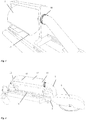
- FIG. 1 shows a chop saw with a machine frame only partially shown, designated 6 and a machine head articulated thereto, which machine head carries a saw blade with a top-side saw blade cover 8.
- the saw blade cover 8 in this case has a connection piece 9, on which a leading to a dust bag 1 connecting line 7 leads.
- a machine frame 6 mounted on the linear guide 3 consisting of two guide rails with four guide grooves or Slotted holes 4 provided, as well as slidably guided therein carriage, which is designed as the dust bag 1 supporting frame 2 and at its front and rear ends each having a pair of guided in the two guide rails pin 5.
- the two guide rails forming the linear guide 3 can be attached to the outer sides of the condyle of the machine frame 6, on which the machine head carrying the saw blade is articulated.
- the dust bag 1 connecting the machine head or the connecting piece 9 on the blade guard 8 connecting line 7 can be designed as a bellows or corrugated pipe or, as shown, as a rubber hose, so that it does not kink in an upward or downward movement of the machine head, but due to his Flexibility or flexibility simply yields something, but translates the pivotal movement of the machine head in a translational movement of together with the frame 2 a dust trap unit forming dust bag 1 along the linear guide 3.
- the flexible connecting line 7 pulls the dust collecting bag 1 in the frame 2 horizontally in the direction of the machine head ( FIG. 2 ). If the machine head is returned to its original position, then the connecting line 7 pushes the dust collecting bag 1 and the frame 2 horizontally back into their starting position ( FIG. 1 ).
- the dust bag 1 To empty the dust bag 1, this can be from his in the FIG. 1 work position shown in a FIG. 3 shown, contrast horizontally pivoted emptying position twist.
- a with the dust bag 1 horizontally rotatable or pivotally supporting axis connected rotary ring 10 is provided with which the dust bag 1 from his in FIG. 1 shown working position in the in FIG. 3 shown emptying position and can pivot back.
- the dust bag 1 At its lower side in the working position, the dust bag 1 has a preferably extending over its entire length zipper 11, which is used to empty the dust bag open.
- FIGS. 4 to 7 Another embodiment of the invention is in the FIGS. 4 to 7 shown. It is in the in the FIGS. 1 to 3 shown embodiment, dimensionally unstable and therefore held over a frame 2 dust bag 1 replaced by a dimensionally stable, advantageously parallelepiped-shaped container 12, which may further advantageously consist of transparent and impact-resistant plastic.
- a carriage 14 may be provided on which the dust collector 12 is simply placed and secured in a known professional art there, for example via clip connections or the like.
- the only one base plate instead of a frame having carriage 14 can then be guided in turn over four pins 5 in a linear guide 3, which as well as the connecting line 7 of those already in connection with the FIGS. 1 to 3 illustrated embodiment of the invention corresponds.
- blower unit 13 in the form of a conventional 12 V DC PC fan 16 with a control unit 17, an on-off switch 18 and a speed controller 20 is mounted, which by a circular opening in the Rear side of the dust collector 12 generates an additional air flow through the dust collector 12 through.
- the PC fan 16 and the control unit 17 are fed, for example, via a wall transformer 20, which supplies the necessary DC voltage.
- the wall transformer 20 has a corresponding plug 21, which is connected to a connection socket of the blower unit 13.
- a battery or battery-operated variant of the blower unit would be conceivable.
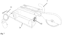
- the dust collector 12 is connected via a clamping ring 22 with the flexible connecting line 7. If the clamping ring 22 is rotated accordingly, then the connecting line 7 can be pulled off. The dust collector 12 can then be removed from the carriage 14, as in FIG. 7 shown to the dust collector 12 to empty.
- the dust collecting container designed as a drawer bottom 23, which is guided in two longitudinal grooves 24 in the vertical side walls of the dust collector 12, so that the dust collector 12 can be emptied.
- the dust collector 12 further comprises two curved baffle plates 15 (FIG. FIG. 4 ), which prevent dust and chips are blown directly through the hole leading to the blower opening 13 in the back wall through back outside.
Landscapes
- Engineering & Computer Science (AREA)
- Mechanical Engineering (AREA)
- Life Sciences & Earth Sciences (AREA)
- Wood Science & Technology (AREA)
- Forests & Forestry (AREA)
- Sawing (AREA)
Abstract
Description
- Die Erfindung betrifft eine Säge, insbesondere eine Kappsäge, Kapp-Gehrungs-Säge oder Kapp-Zug-Gehrungs-Säge gemäß dem Oberbegriff des Anspruchs 1.
- Dementsprechend weist die Säge ein Maschinengestell und einen daran schwenkbar aufgenommenen Maschinenkopf auf, welcher das Sägeblatt trägt. Das Maschinengestell kann beispielsweise in Form eines mit einem Tisch oder einer Unterlage verbundenen Ständers ausgebildet sein, an dem der Maschinenkopf angelenkt ist und in eine von dem Tisch oder der Unterlage abgehobenen Ruhestellung vorgespannt sein kann, aus der er zum Sägen nach unten gedrückt wird.
- Dabei ist herkömmlich meist ein Staubfangsack vorgesehen, der auf einen Absaugstutzen an einem das Sägeblatt oben abdeckenden Sägeblattschutz gesteckt wird, um Staub und Späne, die während des Schneidens entstehen, aufzufangen. Genutzt wird hier der Luftstrom, der durch das rotierende Sägeblatt entsteht. Staub und Späne werden mitgerissen und sammeln sich im Staubfangsack. Eine derartige Säge ist beispielsweise in der europäischen Patentanmeldung
EP 1 990 121 A1 gezeigt. - Nachteilig dabei ist es, dass sich der Staubfangsack mit dem Maschinenkopf beim Einschwenken zum Sägen mitbewegt. Denn wenn der Maschinenkopf zum Sägen nach unten gedrückt wird, befindet sich der Staubfangsack beinahe in vertikaler Position oberhalb des Sägeblatts. Der Luftstrom reicht in dieser Position oft nicht mehr aus, um Staub und Späne in den Staubfangsack zu befördern und dort auch zu halten.
- Die US-Patentanmeldung
US 2004/0089125 A1 offenbart daher schon einen Staubfangsack, der an einem Bett ortsfest und in Form gehalten am Maschinengestell montiert ist und deshalb auch bei einem Verschwenken des Maschinenkopfs nach unten nicht mitverschwenkt. Die nötige Beweglichkeit liefert dabei ein flexibler Anschlusshals des Staubfangsacks, an dem das in einen Bereich des Sägeblatts führende Staubabfuhrrohr angeschlossen ist, welches dann beim Herunterdrücken des Maschinenkopfs von der Sägeblattabdeckung weggedrückt wird. - Ein weiterer Lösungsversuch besteht in der Verwendung schwenkbar ineinander eingreifender und teleskopierbarer Abschnitte der Saugleitung. Eine derartige Anordnung zeigt die europäische Patentschrift
EP 2 377 636 B1 . Diese zeigt eine Kapp-Zug-Säge mit einem feststehend angeordneten Staubauffangbehälter und beweglichem Maschinenkopf mit Sägeblatt, wobei beide mit der auf vorstehend beschriebene Art flexiblen Saugleitung miteinander verbunden sind. - Hiervon ausgehend stellt sich die Aufgabe, eine alternative Lösung zur Überwindung der eingangs geschilderten Nachteile herkömmlicher Sägen der gattungsgemäßen Art zu finden.
- Diese Aufgabe wird mit den Merkmalen des Anspruchs 1 gelöst.
- Bei einer Säge, insbesondere einer Kappsäge, Kapp-Zug-Säge oder Kapp-Zug-Gehrungs-Säge, mit einem an einem Maschinengestell in einer vertikalen Ebene schwenkbeweglich angebrachten Maschinenkopf, welcher zum Sägen aus einer Ruhestellung nach unten drückbar am Maschinengestell aufgenommen ist und ein zum Sägen rotierendes Sägeblatt trägt, und mit einer Staubaufnahme, die zur Aufnahme der während des Sägens anfallenden Späne und Stäube dient und die mit einem Anschlussstutzen an einer oberhalb des Sägeblatts am Maschinenkopf angebrachten Sägeblattabdeckung verbunden ist, ist erfindungsgemäß an dem Maschinengestell eine Linearführung vorgesehen, in der ein Schlitten verschiebbar aufgenommen ist, auf dem die Staubaufnahme angeordnet ist, welche über eine biegsame beziehungsweise flexible Verbindungsleitung mit dem Anschlussstutzen verbunden ist.
- Dadurch, dass die Staubaufnahme auf oder in dem Schlitten sitzt, der entlang der Linearführung am Maschinengestell verschiebbar angebracht ist, wird vermieden, dass die Staubaufnahme bei Herunterdrücken des Maschinenkopfs in die vertikale Stellung oberhalb des Sägeblatts verkippt wird und erreicht, dass die Staubaufnahme lediglich eine lineare Verschiebebewegung macht, wobei die Biegsamkeit beziehungsweise Flexibilität der Verbindungsleitung zwischen dem Absaugstutzen und der Staubaufnahme die unterschiedlichen Bewegungsrichtungen des nach unten verschwenkten Maschinenkopfs beziehungsweise der Sägeblattabdeckung einerseits und der Staubaufnahme andererseits ausgleicht. Die Verbindungsleitung ist dabei also so biegsam, dass sie beim Verschwenken des Maschinenkopfs nicht knickt, sondern die Staubaufnahme zieht beziehungsweise drückt.
- Vorteilhafte Weiterbildungen sind Gegenstand der Unteransprüche.
- So ist es im Hinblick auf eine einfache Beweglichkeit und eine geringe zur Spanabsaugung nötige Luftzufuhr vorteilhaft, wenn die Linearführung so angeordnet ist, dass sie bei auf einer horizontalen Unterlage aufsitzendem Maschinengestell horizontal verläuft.
- Der Schlitten kann dabei als Rahmen ausgebildet sein, welcher die als forminstabiler Staubfangsack ausgebildete Staubaufnahme mehrseitig umgibt. Dadurch kann der forminstabile Staubfangsack aufgespannt und in aufgespannter Form gehalten werden.
- Alternativ dazu kann die Staubaufnahme als formstabiler Behälter ausgebildet sein, beispielsweise als Kunststoffbehälter, so dass ein solches Aufspannen und damit der Rahmen nicht unbedingt nötig ist. Der Schlitten kann dann einfach aus einer Unterlage für den vorzugsweise aus Kunststoff ausgeformten Behälter bestehen. Andererseits wäre es auch denkbar, den Schlitten und den Behälter einstückig auszubilden. Auch bei einem formstabilen Behälter wäre jedoch ein ihn mehrseitig umgebender Rahmen denkbar.
- Dabei kann der formstabile Behälter zur Entnahme der aufgefangenen Späne eine abnehmbare Seitenwand oder eine mit einer Klappe verschließbare Zugriffsöffnung aufweisen, insbesondere an seiner Unterseite. Eine vorteilhafte Ausbildung wäre beispielsweise eine in zwei Nuten geführte Schublade beziehungsweise Verschlussplatte.
- Die Linearführung kann dabei zwei parallele Führungsnuten aufweisen, beispielsweise in Form von zwei Führungsschienen, die am oder nahe des Schwenkgelenks, an dem der Maschinenkopf verschwenkbar am Maschinengestell angebracht ist, ortsfest am Maschinengestell angebracht sind und jeweils eine Längsnut aufweisen. Der Schlitten kann dann vier Zapfen oder Führungskörper aufweisen, je zwei an seinem vorderen und an seinem hinteren Ende, welche voneinander weg abstehen und mit ihren freien Enden nach außen hin in die dortige Führungsnut hineinragen und somit dort geführt werden. Dadurch ist sichergestellt, dass der Schlitten und damit der darauf angebrachte Behälter oder Staubfangsack eine rein translatorische Bewegung durchführen.
- Die Flexibilität beziehungsweise Biegsamkeit der Verbindungsleitung kann dabei beispielsweise dadurch hergestellt werden, dass sie als Faltenrohr beziehungsweise Faltenbalg oder Gummischlauch ausgebildet ist.
- Insbesondere bei einer als Staubaufnahmesack ausgebildeten Staubaufnahme kann dabei ein Reißverschluss vorgesehen sein, um Zugriff auf das Innere der Staubaufnahme zum Ausleeren zu gewähren.
- Die Staubaufnahme kann dabei horizontal schwenkbar und gegen horizontales Verschwenken lösbar gesichert in dem Rahmen aufgenommen sein. Beispielsweise könnten zwischen zwei vertikalen Rahmenstreben vor und hinter der vorzugsweise als Staubfangsack gestalteten Staubaufnahme Drehgelenke angebracht sein, an denen die Staubaufnahme horizontal drehbar beziehungsweise schwenkbar an dem Rahmen angebracht ist. Der Reißverschluss könnte sich dann an einer Stelle des Staubfangsacks befinden, der im Einsatzfall der Säge unten im dem Schlittenboden zugewandten Bereich angeordnet und dadurch geschützt ist. Zum Leeren des Staubfangsacks kann dieser dann horizontal ausgeschwenkt werden, bis der Reißverschluss zugänglich ist.
- Weiterhin vorteilhaft ist es, insbesondere bei einem als Kunststoffbehälter ausgebildeten und daher zunächst luftundurchlässigen Staubfangbehälter, wenn eine zusätzliche Gebläseeinheit, beispielsweise in Form eines handelsüblichen PC-12V-Lüfters vorgesehen ist, welche einen Luftzug durch die Staubaufnahme erzeugt, wozu die als Kunststoffbehälter ausgebildete Staubaufnahme vorteilhaft eine der Gebläseeinheit zugeordnete Öffnung aufweist, welche mittels eines Filterelements und/oder eines oder mehrerer Ablenkelemente, wie beispielsweise einer Ablenkplatte, verdeckt ist. Auch am Einlass des Staubaufnahmebehälters kann eine solche Prallplatte beziehungsweise Ablenkplatte vorgesehen sein, um den Luftstrom zunächst zum Boden des Behälters hin zu lenken.
- Die Verbindungsleitung kann dabei vorteilhaft über einen Dreh- oder Klemmring direkt mit der Staubaufnahme oder mit dem die Staubaufnahme tragenden Rahmen verbunden sein, wobei sich der Ring öffnen und schließen lässt, um die Verbindungsleitung einerseits von der Staubaufnahmeeinheit andererseits (bestehend aus dem Schlitten und der Staubaufnahme) zu trennen. Es wäre auch denkbar, den Drehring auf der horizontalen Schwenkachse des Staubfangsacks aufzusetzen, so dass dieser gleichzeitig zum horizontalen Ausschwenken des Staubfangsacks in die Entnahmestellung verwendet werden kann.
- Vorteilhaft ist die Staubaufnahme dabei auf dem Schlitten lösbar befestigt und somit abnehmbar, insbesondere wenn es sich um eine als formstabilen Behälter ausgebildete Staubaufnahme handelt, so dass sie sich leicht entleeren lässt.
- In den beiliegenden Zeichnungen werden vorteilhafte Ausführungsformen der Erfindung dargestellt. Es zeigen:
- Figur 1
- eine perspektivische Ansicht einer Säge gemäß einer vorteilhaften Ausführungsform der Erfindung in Ruhestellung;
- Figur 2
- die in
Figur 1 gezeigte Säge in Sägestellung; - Figur 3
- eine perspektivische Teilansicht der in
Figur 1 und 2 in Ruhestellung gezeigten Säge bei zur Leerung ausgeschwenktem Staubfangsack; - Figur 4
- eine perspektivische Ansicht einer Säge gemäß einer weiteren Ausführungsform der Erfindung in Sägestellung;
- Figur 5
- eine weitere perspektivische Ansicht der in
Figur 4 gezeigten Säge in Sägestellung von der rückwärtigen Seite aus; - Figur 6
- eine perspektivische Teilansicht der Rückseite der in den
Figuren 4 und5 gezeigten Säge; und - Figur 7
- die in den
Figuren 4 bis 6 gezeigte Säge bei abgenommenem Staubfangbehälter. - Zunächst wird Bezug genommen auf die
Figur 1 , welche eine Kappsäge mit einem nur teilweise gezeigten, mit 6 bezeichneten Maschinengestell und einem daran angelenkten Maschinenkopf zeigt, welcher Maschinenkopf ein Sägeblatt mit einer oberseitigen Sägeblattabdeckung 8 trägt. Zum Sägen wird der Maschinenkopf mit dem Sägeblatt dabei aus der in derFigur 1 gezeigten, angehobenen Stellung nach unten in die inFigur 2 gezeigte Sägestellung verschwenkt. Die Sägeblattabdeckung 8 weist dabei einen Anschlussstutzen 9 auf, an dem eine zu einem Staubfangsack 1 führende Verbindungsleitung 7 führt. - Um die nötige Bewegungsfreiheit des Maschinenkopfs sicherzustellen und gleichzeitig ein Mitverschwenken des Staubfangsacks 1 mit dem Maschinenkopf zu vermeiden, ist dabei eine am Maschinengestell 6 angebrachte Linearführung 3, bestehend aus zwei Führungsschienen mit vier Führungsnuten beziehungsweise Langlöchern 4 vorgesehen, sowie ein darin verschiebbar geführter Schlitten, der als den Staubfangsack 1 tragender Rahmen 2 gestaltet ist und an seinem vorderen und hinteren Ende jeweils ein Paar von in den beiden Führungsschienen geführten Zapfen 5 aufweist. Die beiden die Linearführung 3 bildenden Führungsschienen können dabei an den Außenseiten des Gelenkkopfs des Maschinengestells 6 angebracht sein, an dem der das Sägeblatt tragende Maschinenkopf angelenkt ist.
- Die den Staubfangsack 1 mit dem Maschinenkopf beziehungsweise dem Anschlussstutzen 9 am Sägeblattschutz 8 verbindende Verbindungsleitung 7 kann dabei als Faltenbalg beziehungsweise Faltenrohr oder, wie dargestellt, als Gummischlauch ausgebildet sein, so dass es bei einer Aufwärts- oder Abwärtsbewegung des Maschinenkopfs nicht abknickt, sondern aufgrund seiner Biegsamkeit beziehungsweise Flexibilität einfach etwas nachgibt, aber die Schwenkbewegung des Maschinenkopfs in eine Translationsbewegung des zusammen mit dem Rahmen 2 eine Staubfangeinheit bildenden Staubfangsacks 1 entlang der Linearführung 3 übersetzt.
- Wird der Maschinenkopf nach unten gedrückt, so zieht die flexible Verbindungsleitung 7 den Staubfangsack 1 in dem Rahmen 2 horizontal in Richtung zum Maschinenkopf hin (
Figur 2 ). Wird der Maschinenkopf wieder in seine Ausgangsposition zurückgeführt, so schiebt die Verbindungsleitung 7 den Staubfangsack 1 und den Rahmen 2 horizontal wieder in ihre Ausgangsposition (Figur 1 ). - Um den Staubfangsack 1 zu entleeren, lässt sich dieser aus seiner in der
Figur 1 gezeigten Arbeitsstellung in eine inFigur 3 gezeigte, demgegenüber horizontal verschwenkte Leerungsstellung verdrehen. Dazu ist ein mit einer den Staubfangsack 1 horizontal drehbar beziehungsweise verschwenkbar tragenden Achse verbundener Drehring 10 vorgesehen, mit dem sich der Staubfangsack 1 aus seiner inFigur 1 gezeigten Arbeitsstellung in die inFigur 3 gezeigte Leerungsstellung und zurück verschwenken lässt. An seiner in Arbeitsstellung unten gelegenen Seite weist der Staubfangsack 1 dabei einen sich vorzugsweise über seine gesamte Länge erstreckenden Reißverschluss 11 auf, der sich zum Leeren des Staubfangsacks öffnen lässt. - Eine weitere Ausführungsform der Erfindung ist in den
Figuren 4 bis 7 dargestellt. Dabei ist der bei der in denFiguren 1 bis 3 gezeigten Ausführungsform vorgesehene, forminstabile und daher über einen Rahmen 2 gehaltene Staubfangsack 1 durch einen formstabilen, vorteilhaft quaderförmigen Behälter 12 ersetzt, der weiterhin vorteilhaft aus transparentem und schlagfestem Kunststoff bestehen kann. Anstatt eines den forminstabilen Staubfangsack mehrseitig umgebenden Rahmens kann hier ein Schlitten 14 vorgesehen sein, auf dem der Staubfangbehälter 12 einfach aufgestellt und auf fachnotorisch bekannte Art dort befestigt ist, beispielsweise über Klipsverbindungen oder dergleichen. Der lediglich eine Bodenplatte anstatt eines Rahmens aufweisende Schlitten 14 kann dann wiederum über vier Zapfen 5 in einer Linearführung 3 geführt sein, die ebenso wie die Verbindungsleitung 7 derjenigen aus der bereits im Zusammenhang mit denFiguren 1 bis 3 erläuterten Ausführungsform der Erfindung entspricht. - Am dem Maschinenkopf abgewandten, also rückseitigen Ende des Kunststoffbehälters ist dabei eine Gebläseeinheit 13 in Form eines gewöhnlichen 12 V-Gleichstrom PC-Lüfters 16 mit einer Steuereinheit 17, einem Ein-Ausschalter 18 und einem Drehzahlregler 20 angebracht, die durch eine kreisrunde Öffnung in der Rückseite des Staubfangbehälters 12 einen zusätzlichen Luftstrom durch den Staubfangbehälter 12 hindurch erzeugt. Gespeist werden der PC-Lüfter 16 und die Steuereinheit 17 beispielsweise über einen Wandtransformator 20, der die notwendige Gleichspannung liefert. Der Wandtransformator 20 besitzt einen entsprechenden Stecker 21, der mit einer Anschlussbuchse der Gebläseeinheit 13 verbunden ist. Alternativ wäre auch eine batterie- beziehungsweise akkubetriebene Variante der Gebläseeinheit denkbar.
- Der Staubfangbehälter 12 ist über einen Klemmring 22 mit der flexiblen Verbindungsleitung 7 verbunden. Wird der Klemmring 22 entsprechend gedreht, so lässt sich die Verbindungsleitung 7 abziehen. Der Staubfangbehälter 12 kann dann vom Schlitten 14 abgenommen werden, wie in
Figur 7 gezeigt, um den Staubfangbehälter 12 zu entleeren. Dazu weist der Staubfangbehälter eine als Schublade 23 ausgestaltete Unterseite auf, welche in zwei Längsnuten 24 in den vertikalen Seitenwänden des Staubfangbehälters 12 geführt ist, so dass der Staubfangbehälter 12 entleert werden kann. - Der Staubfangbehälter 12 weist des Weiteren zwei kurvenförmig gebogene Ablenkplatten 15 auf (
Figur 4 ), die verhindern, dass Staub und Späne direkt durch das zur Gebläseöffnung 13 führende Loch in der Rückwand hindurch wieder nach draußen geblasen werden. - Abwandlungen und Modifikationen der gezeigten Ausführungsformen sind möglich, ohne den Rahmen der Erfindung zu verlassen.
Claims (13)
- Säge, insbesondere Kappsäge, Kapp-Zug-Säge oder Kapp-Zug-Gehrungs-Säge, mit einem an einem Maschinengestell in einer vertikalen Ebene schwenkbeweglich angebrachten Maschinenkopf, welcher zum Sägen aus einer Ruhestellung nach unten drückbar am Maschinengestell (6) aufgenommen ist und ein zum Sägen rotierendes Sägeblatt trägt, und mit einer Staubaufnahme, die zur Aufnahme der während des Sägens anfallenden Späne und Stäube dient und die mit einem Anschlussstutzen (9) an einer oberhalb des Sägeblatts am Maschinenkopf angebrachten Sägeblattabdeckung (8) verbunden ist,
dadurch kennzeichnet, dass
an dem Maschinengestell (6) eine Linearführung (3) vorgesehen ist und die Staubaufnahme auf einem in der Linearführung (3) verschiebbar aufgenommenen Schlitten angeordnet ist, wobei die Staubaufnahme über eine biegsame Verbindungsleitung mit dem Anschlussstutzen (9) verbunden ist. - Säge nach Anspruch 1, dadurch kennzeichnet, dass die Linearführung (3) so angeordnet ist, dass sie bei auf einer horizontalen Unterlage aufsitzendem Maschinengestell (6) horizontal verläuft.
- Säge nach Anspruch 1 oder 2, dadurch kennzeichnet, dass der Schlitten als Rahmen (2) ausgebildet ist, welcher die als forminstabiler Staubfangsack (1) ausgebildete Staubaufnahme mehrseitig umgibt.
- Säge nach Anspruch 1 oder 2, dadurch kennzeichnet, dass der die Staubaufnahme als formstabiler Behälter (12) insbesondere aus Kunststoff ausgebildet ist und einstückig mit dem Schlitten oder auf dem Schlitten (14) angeordnet ist.
- Säge nach Anspruch 4, dadurch kennzeichnet, dass der Behälter eine abnehmbare Seitenwand aufweist, insbesondere an seiner Unterseite, vorzugsweise in Form einer in zwei Nuten (24) geführten Schublade (23).
- Säge nach einem der vorhergehenden Ansprüche, dadurch kennzeichnet, dass die Linearführung (3) zwei parallele Führungsnuten (4) aufweist und der Schlitten je zwei an seinen vorderen und hinteren Enden voneinander weg abstehende Zapfen (5), die in die beiden Führungsnuten (4) hineinragen.
- Säge nach einem der vorhergehenden Ansprüche, dadurch kennzeichnet, dass die Verbindungsleitung als Faltenbalg (6) oder Gummischlauch ausgebildet ist.
- Säge nach einem der vorhergehenden Ansprüche, dadurch kennzeichnet, dass ein zur Staubentnahme dienender Reißverschluss (11) an der Staubaufnahme angebracht ist.
- Säge nach Anspruch 8, dadurch kennzeichnet, dass die Staubaufnahme horizontal schwenkbar und gegen horizontales Verschwenken lösbar gesichert in dem Rahmen (2) aufgenommen ist, wobei der Reißverschluss (11) in einer ausgeschwenkten Entnahmestellung der Staubaufnahme zugänglich ist und in einer Arbeitsstellung nicht.
- Säge nach einem der vorhergehenden Ansprüche, dadurch kennzeichnet, dass eine Gebläseeinheit (13), beispielsweise ein 12V-Lüfter, vorgesehen ist, welche einen Luftzug durch die Staubaufnahme erzeugt, wobei die Gebläseeinheit vorzugsweise auf der dem Sägeblatt abgewandten Seite der Staubaufnahme, angeordnet ist.
- Säge nach Anspruch 10, dadurch kennzeichnet, dass die Staubaufnahme eine der Gebläseeinheit (13) zugeordnete Öffnung aufweist, welche mittels eines Filterelements und/oder eines Ablenkelements (15) verdeckt ist.
- Säge nach einem der vorhergehenden Ansprüche, dadurch kennzeichnet, dass die Verbindungsleitung über einen öffnen- und schließbaren Klemm- oder Drehring (22) mit der Staubaufnahme verbunden ist.
- Säge nach einem der vorhergehenden Ansprüche, dadurch kennzeichnet, dass die Staubaufnahme auf dem Schlitten lösbar befestigt und daher abnehmbar ist.
Priority Applications (3)
| Application Number | Priority Date | Filing Date | Title |
|---|---|---|---|
| EP17020438.2A EP3459666B1 (de) | 2017-09-22 | 2017-09-22 | Säge |
| AU2018220163A AU2018220163B1 (en) | 2017-09-22 | 2018-08-25 | Saw |
| US16/135,939 US20190091781A1 (en) | 2017-09-22 | 2018-09-19 | Saw having a dust collector |
Applications Claiming Priority (1)
| Application Number | Priority Date | Filing Date | Title |
|---|---|---|---|
| EP17020438.2A EP3459666B1 (de) | 2017-09-22 | 2017-09-22 | Säge |
Publications (2)
| Publication Number | Publication Date |
|---|---|
| EP3459666A1 true EP3459666A1 (de) | 2019-03-27 |
| EP3459666B1 EP3459666B1 (de) | 2020-08-12 |
Family
ID=59955322
Family Applications (1)
| Application Number | Title | Priority Date | Filing Date |
|---|---|---|---|
| EP17020438.2A Active EP3459666B1 (de) | 2017-09-22 | 2017-09-22 | Säge |
Country Status (3)
| Country | Link |
|---|---|
| US (1) | US20190091781A1 (de) |
| EP (1) | EP3459666B1 (de) |
| AU (1) | AU2018220163B1 (de) |
Families Citing this family (2)
| Publication number | Priority date | Publication date | Assignee | Title |
|---|---|---|---|---|
| DE102023110817A1 (de) * | 2023-04-26 | 2024-10-31 | Festool Gmbh | Auffangbehältnis für Werkstückpartikel, Baugruppe umfassend ein motorisch angetriebenes Handwerkzeug und ein Auffangbehältnis sowie Verfahren zum Entleeren eines Auffangbehältnisses |
| CN117301231B (zh) * | 2023-11-29 | 2024-02-13 | 长春市大亚木业有限公司 | 一种家具板材生产用智能化除尘装置 |
Citations (6)
| Publication number | Priority date | Publication date | Assignee | Title |
|---|---|---|---|---|
| DE4140577A1 (de) * | 1991-04-15 | 1992-10-22 | Wilfried Pavel Maschinenbau Fa | Vorrichtung zur bildung einer kompakten kunststoffmasse aus gebrauchten kunststoffolien und/oder kunststoffolien-abfaellen |
| US20040089125A1 (en) | 2002-11-08 | 2004-05-13 | Emerson Electric Co. | Compound miter saw |
| EP1625908A1 (de) * | 2004-07-16 | 2006-02-15 | Makita Corporation | Staubsaugvorrichtungen und Schneidvorrichtungen mit diesen Staubsaugvorrichtungen |
| EP1990121A1 (de) | 2007-05-08 | 2008-11-12 | Makita Corporation | Staubsammelvorrichtungen für ein Bearbeitungsgerät |
| EP2388097A1 (de) * | 2010-05-20 | 2011-11-23 | Makita Corporation | Staubsammelvorrichtungen |
| EP2377636B1 (de) | 2010-04-15 | 2015-10-21 | Makita Corporation | Schneidevorrichtung |
Family Cites Families (7)
| Publication number | Priority date | Publication date | Assignee | Title |
|---|---|---|---|---|
| US4721023A (en) * | 1986-06-20 | 1988-01-26 | Shopsmith, Inc. | Saw guard system |
| US20030047895A1 (en) * | 2001-09-07 | 2003-03-13 | Mcelroy Robert D. | Mobile saw cart |
| TW537158U (en) * | 2002-07-15 | 2003-06-11 | Pei-Lie Jiang | Bit collecting bag apparatus for carpentry machine |
| TW569907U (en) * | 2002-09-26 | 2004-01-01 | P & F Brother Ind Corp | Dust collecting structure for supporting seat of cutting machine |
| US20090139048A1 (en) * | 2007-11-30 | 2009-06-04 | Williams Danny P | Power tool dust-collecting assembly and accessories |
| WO2014151826A1 (en) * | 2013-03-15 | 2014-09-25 | Robert Bosch Gmbh | Dust collection system for a circular saw |
| WO2018195868A2 (zh) * | 2017-04-27 | 2018-11-01 | 永康市丛臻工具有限公司 | 一种无尘多功能切割机 |
-
2017
- 2017-09-22 EP EP17020438.2A patent/EP3459666B1/de active Active
-
2018
- 2018-08-25 AU AU2018220163A patent/AU2018220163B1/en not_active Ceased
- 2018-09-19 US US16/135,939 patent/US20190091781A1/en not_active Abandoned
Patent Citations (6)
| Publication number | Priority date | Publication date | Assignee | Title |
|---|---|---|---|---|
| DE4140577A1 (de) * | 1991-04-15 | 1992-10-22 | Wilfried Pavel Maschinenbau Fa | Vorrichtung zur bildung einer kompakten kunststoffmasse aus gebrauchten kunststoffolien und/oder kunststoffolien-abfaellen |
| US20040089125A1 (en) | 2002-11-08 | 2004-05-13 | Emerson Electric Co. | Compound miter saw |
| EP1625908A1 (de) * | 2004-07-16 | 2006-02-15 | Makita Corporation | Staubsaugvorrichtungen und Schneidvorrichtungen mit diesen Staubsaugvorrichtungen |
| EP1990121A1 (de) | 2007-05-08 | 2008-11-12 | Makita Corporation | Staubsammelvorrichtungen für ein Bearbeitungsgerät |
| EP2377636B1 (de) | 2010-04-15 | 2015-10-21 | Makita Corporation | Schneidevorrichtung |
| EP2388097A1 (de) * | 2010-05-20 | 2011-11-23 | Makita Corporation | Staubsammelvorrichtungen |
Also Published As
| Publication number | Publication date |
|---|---|
| US20190091781A1 (en) | 2019-03-28 |
| AU2018220163B1 (en) | 2019-04-18 |
| EP3459666B1 (de) | 2020-08-12 |
Similar Documents
| Publication | Publication Date | Title |
|---|---|---|
| EP3047944B1 (de) | Anordnung mit einem handgeführten arbeitsgerät und mit einer abstützvorrichtung und handgeführtes arbeitsgerät | |
| US6796208B1 (en) | Sawdust collection hood for table saw | |
| DE60215719T2 (de) | Staubsammler für ein Kraftwerkzeug | |
| DE19750543A1 (de) | Tragbares Sauggerät | |
| DE4411526A1 (de) | Saugreinigungsgerät | |
| EP2815842B1 (de) | Staubsammelvorrichtung für eine Hand-Werkzeugmaschine und Hand-Werkzeugmaschine | |
| DE10297496T5 (de) | Bodenstaubsauger | |
| DE2351769B2 (de) | Saugeinheit | |
| EP3459666B1 (de) | Säge | |
| DE3615736A1 (de) | Kreissaege, insbesondere handkreissaege | |
| DE102015108052B4 (de) | Saugdüse zur Aufnahme von Grobgut und Feinstaub | |
| EP0930134B1 (de) | Medizintechnischer oder dentaltechnischer Arbeitstisch | |
| EP0784922A2 (de) | Mobile Vorrichtung zum Ansaugen von Laub oder dergleichen Gut | |
| EP0956806B1 (de) | Sauggerät zum Ansaugen von Schmutz od.dgl. enthaltendem Sauggut | |
| DE202005002979U1 (de) | Sauggerät | |
| EP0598246B1 (de) | Zahntechnischer Arbeitsplatz mit einem Arbeitstisch und einer Absaugeinrichtung mit einem Filtergerät | |
| DE10209325B4 (de) | Elektrohandwerkzeug | |
| EP1697087B1 (de) | Elektrohandwerkzeugmaschine | |
| EP3944940B1 (de) | Sägemaschine | |
| DE29603771U1 (de) | Absaugeinrichtung | |
| DE202006010774U1 (de) | Holzbearbeitungsmaschine | |
| EP3409162B1 (de) | In der hand gehaltener staubsauger mit einem abgeschrägten teil der bodenfläche der staubabscheidevorrichtung | |
| DE3816098C2 (de) | ||
| DE3246833A1 (de) | Rollbarer reinigungswagen | |
| DE202010000380U1 (de) | Schutzhaube |
Legal Events
| Date | Code | Title | Description |
|---|---|---|---|
| PUAI | Public reference made under article 153(3) epc to a published international application that has entered the european phase |
Free format text: ORIGINAL CODE: 0009012 |
|
| STAA | Information on the status of an ep patent application or granted ep patent |
Free format text: STATUS: REQUEST FOR EXAMINATION WAS MADE |
|
| 17P | Request for examination filed |
Effective date: 20180717 |
|
| AK | Designated contracting states |
Kind code of ref document: A1 Designated state(s): AL AT BE BG CH CY CZ DE DK EE ES FI FR GB GR HR HU IE IS IT LI LT LU LV MC MK MT NL NO PL PT RO RS SE SI SK SM TR |
|
| AX | Request for extension of the european patent |
Extension state: BA ME |
|
| GRAP | Despatch of communication of intention to grant a patent |
Free format text: ORIGINAL CODE: EPIDOSNIGR1 |
|
| STAA | Information on the status of an ep patent application or granted ep patent |
Free format text: STATUS: GRANT OF PATENT IS INTENDED |
|
| INTG | Intention to grant announced |
Effective date: 20191218 |
|
| GRAJ | Information related to disapproval of communication of intention to grant by the applicant or resumption of examination proceedings by the epo deleted |
Free format text: ORIGINAL CODE: EPIDOSDIGR1 |
|
| STAA | Information on the status of an ep patent application or granted ep patent |
Free format text: STATUS: REQUEST FOR EXAMINATION WAS MADE |
|
| INTC | Intention to grant announced (deleted) | ||
| GRAJ | Information related to disapproval of communication of intention to grant by the applicant or resumption of examination proceedings by the epo deleted |
Free format text: ORIGINAL CODE: EPIDOSDIGR1 |
|
| GRAP | Despatch of communication of intention to grant a patent |
Free format text: ORIGINAL CODE: EPIDOSNIGR1 |
|
| GRAR | Information related to intention to grant a patent recorded |
Free format text: ORIGINAL CODE: EPIDOSNIGR71 |
|
| GRAS | Grant fee paid |
Free format text: ORIGINAL CODE: EPIDOSNIGR3 |
|
| STAA | Information on the status of an ep patent application or granted ep patent |
Free format text: STATUS: GRANT OF PATENT IS INTENDED |
|
| GRAA | (expected) grant |
Free format text: ORIGINAL CODE: 0009210 |
|
| STAA | Information on the status of an ep patent application or granted ep patent |
Free format text: STATUS: THE PATENT HAS BEEN GRANTED |
|
| AK | Designated contracting states |
Kind code of ref document: B1 Designated state(s): AL AT BE BG CH CY CZ DE DK EE ES FI FR GB GR HR HU IE IS IT LI LT LU LV MC MK MT NL NO PL PT RO RS SE SI SK SM TR |
|
| INTG | Intention to grant announced |
Effective date: 20200707 |
|
| REG | Reference to a national code |
Ref country code: CH Ref legal event code: EP |
|
| REG | Reference to a national code |
Ref country code: CH Ref legal event code: NV Representative=s name: PATENTANWAELTE MUNK, DE |
|
| REG | Reference to a national code |
Ref country code: IE Ref legal event code: FG4D Free format text: LANGUAGE OF EP DOCUMENT: GERMAN |
|
| REG | Reference to a national code |
Ref country code: DE Ref legal event code: R096 Ref document number: 502017006666 Country of ref document: DE |
|
| REG | Reference to a national code |
Ref country code: AT Ref legal event code: REF Ref document number: 1301062 Country of ref document: AT Kind code of ref document: T Effective date: 20200915 |
|
| REG | Reference to a national code |
Ref country code: SE Ref legal event code: TRGR |
|
| REG | Reference to a national code |
Ref country code: LT Ref legal event code: MG4D |
|
| REG | Reference to a national code |
Ref country code: NL Ref legal event code: MP Effective date: 20200812 |
|
| PG25 | Lapsed in a contracting state [announced via postgrant information from national office to epo] |
Ref country code: HR Free format text: LAPSE BECAUSE OF FAILURE TO SUBMIT A TRANSLATION OF THE DESCRIPTION OR TO PAY THE FEE WITHIN THE PRESCRIBED TIME-LIMIT Effective date: 20200812 Ref country code: BG Free format text: LAPSE BECAUSE OF FAILURE TO SUBMIT A TRANSLATION OF THE DESCRIPTION OR TO PAY THE FEE WITHIN THE PRESCRIBED TIME-LIMIT Effective date: 20201112 Ref country code: LT Free format text: LAPSE BECAUSE OF FAILURE TO SUBMIT A TRANSLATION OF THE DESCRIPTION OR TO PAY THE FEE WITHIN THE PRESCRIBED TIME-LIMIT Effective date: 20200812 Ref country code: FI Free format text: LAPSE BECAUSE OF FAILURE TO SUBMIT A TRANSLATION OF THE DESCRIPTION OR TO PAY THE FEE WITHIN THE PRESCRIBED TIME-LIMIT Effective date: 20200812 Ref country code: NO Free format text: LAPSE BECAUSE OF FAILURE TO SUBMIT A TRANSLATION OF THE DESCRIPTION OR TO PAY THE FEE WITHIN THE PRESCRIBED TIME-LIMIT Effective date: 20201112 Ref country code: GR Free format text: LAPSE BECAUSE OF FAILURE TO SUBMIT A TRANSLATION OF THE DESCRIPTION OR TO PAY THE FEE WITHIN THE PRESCRIBED TIME-LIMIT Effective date: 20201113 |
|
| PG25 | Lapsed in a contracting state [announced via postgrant information from national office to epo] |
Ref country code: LV Free format text: LAPSE BECAUSE OF FAILURE TO SUBMIT A TRANSLATION OF THE DESCRIPTION OR TO PAY THE FEE WITHIN THE PRESCRIBED TIME-LIMIT Effective date: 20200812 Ref country code: NL Free format text: LAPSE BECAUSE OF FAILURE TO SUBMIT A TRANSLATION OF THE DESCRIPTION OR TO PAY THE FEE WITHIN THE PRESCRIBED TIME-LIMIT Effective date: 20200812 Ref country code: RS Free format text: LAPSE BECAUSE OF FAILURE TO SUBMIT A TRANSLATION OF THE DESCRIPTION OR TO PAY THE FEE WITHIN THE PRESCRIBED TIME-LIMIT Effective date: 20200812 Ref country code: PL Free format text: LAPSE BECAUSE OF FAILURE TO SUBMIT A TRANSLATION OF THE DESCRIPTION OR TO PAY THE FEE WITHIN THE PRESCRIBED TIME-LIMIT Effective date: 20200812 Ref country code: IS Free format text: LAPSE BECAUSE OF FAILURE TO SUBMIT A TRANSLATION OF THE DESCRIPTION OR TO PAY THE FEE WITHIN THE PRESCRIBED TIME-LIMIT Effective date: 20201212 |
|
| PG25 | Lapsed in a contracting state [announced via postgrant information from national office to epo] |
Ref country code: SM Free format text: LAPSE BECAUSE OF FAILURE TO SUBMIT A TRANSLATION OF THE DESCRIPTION OR TO PAY THE FEE WITHIN THE PRESCRIBED TIME-LIMIT Effective date: 20200812 Ref country code: EE Free format text: LAPSE BECAUSE OF FAILURE TO SUBMIT A TRANSLATION OF THE DESCRIPTION OR TO PAY THE FEE WITHIN THE PRESCRIBED TIME-LIMIT Effective date: 20200812 Ref country code: CZ Free format text: LAPSE BECAUSE OF FAILURE TO SUBMIT A TRANSLATION OF THE DESCRIPTION OR TO PAY THE FEE WITHIN THE PRESCRIBED TIME-LIMIT Effective date: 20200812 Ref country code: DK Free format text: LAPSE BECAUSE OF FAILURE TO SUBMIT A TRANSLATION OF THE DESCRIPTION OR TO PAY THE FEE WITHIN THE PRESCRIBED TIME-LIMIT Effective date: 20200812 Ref country code: RO Free format text: LAPSE BECAUSE OF FAILURE TO SUBMIT A TRANSLATION OF THE DESCRIPTION OR TO PAY THE FEE WITHIN THE PRESCRIBED TIME-LIMIT Effective date: 20200812 |
|
| REG | Reference to a national code |
Ref country code: DE Ref legal event code: R097 Ref document number: 502017006666 Country of ref document: DE |
|
| PG25 | Lapsed in a contracting state [announced via postgrant information from national office to epo] |
Ref country code: ES Free format text: LAPSE BECAUSE OF FAILURE TO SUBMIT A TRANSLATION OF THE DESCRIPTION OR TO PAY THE FEE WITHIN THE PRESCRIBED TIME-LIMIT Effective date: 20200812 Ref country code: AL Free format text: LAPSE BECAUSE OF FAILURE TO SUBMIT A TRANSLATION OF THE DESCRIPTION OR TO PAY THE FEE WITHIN THE PRESCRIBED TIME-LIMIT Effective date: 20200812 Ref country code: MC Free format text: LAPSE BECAUSE OF FAILURE TO SUBMIT A TRANSLATION OF THE DESCRIPTION OR TO PAY THE FEE WITHIN THE PRESCRIBED TIME-LIMIT Effective date: 20200812 |
|
| PLBE | No opposition filed within time limit |
Free format text: ORIGINAL CODE: 0009261 |
|
| REG | Reference to a national code |
Ref country code: BE Ref legal event code: MM Effective date: 20200930 |
|
| STAA | Information on the status of an ep patent application or granted ep patent |
Free format text: STATUS: NO OPPOSITION FILED WITHIN TIME LIMIT |
|
| PG25 | Lapsed in a contracting state [announced via postgrant information from national office to epo] |
Ref country code: LU Free format text: LAPSE BECAUSE OF NON-PAYMENT OF DUE FEES Effective date: 20200922 Ref country code: SK Free format text: LAPSE BECAUSE OF FAILURE TO SUBMIT A TRANSLATION OF THE DESCRIPTION OR TO PAY THE FEE WITHIN THE PRESCRIBED TIME-LIMIT Effective date: 20200812 |
|
| 26N | No opposition filed |
Effective date: 20210514 |
|
| PG25 | Lapsed in a contracting state [announced via postgrant information from national office to epo] |
Ref country code: IT Free format text: LAPSE BECAUSE OF FAILURE TO SUBMIT A TRANSLATION OF THE DESCRIPTION OR TO PAY THE FEE WITHIN THE PRESCRIBED TIME-LIMIT Effective date: 20200812 |
|
| PG25 | Lapsed in a contracting state [announced via postgrant information from national office to epo] |
Ref country code: BE Free format text: LAPSE BECAUSE OF NON-PAYMENT OF DUE FEES Effective date: 20200930 Ref country code: SI Free format text: LAPSE BECAUSE OF FAILURE TO SUBMIT A TRANSLATION OF THE DESCRIPTION OR TO PAY THE FEE WITHIN THE PRESCRIBED TIME-LIMIT Effective date: 20200812 Ref country code: IE Free format text: LAPSE BECAUSE OF NON-PAYMENT OF DUE FEES Effective date: 20200922 |
|
| PGFP | Annual fee paid to national office [announced via postgrant information from national office to epo] |
Ref country code: CH Payment date: 20210923 Year of fee payment: 5 Ref country code: FR Payment date: 20210927 Year of fee payment: 5 |
|
| PGFP | Annual fee paid to national office [announced via postgrant information from national office to epo] |
Ref country code: SE Payment date: 20210921 Year of fee payment: 5 Ref country code: DE Payment date: 20210930 Year of fee payment: 5 Ref country code: GB Payment date: 20210923 Year of fee payment: 5 |
|
| PG25 | Lapsed in a contracting state [announced via postgrant information from national office to epo] |
Ref country code: TR Free format text: LAPSE BECAUSE OF FAILURE TO SUBMIT A TRANSLATION OF THE DESCRIPTION OR TO PAY THE FEE WITHIN THE PRESCRIBED TIME-LIMIT Effective date: 20200812 Ref country code: MT Free format text: LAPSE BECAUSE OF FAILURE TO SUBMIT A TRANSLATION OF THE DESCRIPTION OR TO PAY THE FEE WITHIN THE PRESCRIBED TIME-LIMIT Effective date: 20200812 Ref country code: CY Free format text: LAPSE BECAUSE OF FAILURE TO SUBMIT A TRANSLATION OF THE DESCRIPTION OR TO PAY THE FEE WITHIN THE PRESCRIBED TIME-LIMIT Effective date: 20200812 |
|
| PG25 | Lapsed in a contracting state [announced via postgrant information from national office to epo] |
Ref country code: MK Free format text: LAPSE BECAUSE OF FAILURE TO SUBMIT A TRANSLATION OF THE DESCRIPTION OR TO PAY THE FEE WITHIN THE PRESCRIBED TIME-LIMIT Effective date: 20200812 |
|
| PG25 | Lapsed in a contracting state [announced via postgrant information from national office to epo] |
Ref country code: PT Free format text: LAPSE BECAUSE OF FAILURE TO SUBMIT A TRANSLATION OF THE DESCRIPTION OR TO PAY THE FEE WITHIN THE PRESCRIBED TIME-LIMIT Effective date: 20200812 |
|
| REG | Reference to a national code |
Ref country code: DE Ref legal event code: R119 Ref document number: 502017006666 Country of ref document: DE |
|
| REG | Reference to a national code |
Ref country code: CH Ref legal event code: PL |
|
| REG | Reference to a national code |
Ref country code: SE Ref legal event code: EUG |
|
| GBPC | Gb: european patent ceased through non-payment of renewal fee |
Effective date: 20220922 |
|
| PG25 | Lapsed in a contracting state [announced via postgrant information from national office to epo] |
Ref country code: LI Free format text: LAPSE BECAUSE OF NON-PAYMENT OF DUE FEES Effective date: 20220930 Ref country code: FR Free format text: LAPSE BECAUSE OF NON-PAYMENT OF DUE FEES Effective date: 20220930 Ref country code: DE Free format text: LAPSE BECAUSE OF NON-PAYMENT OF DUE FEES Effective date: 20230401 Ref country code: CH Free format text: LAPSE BECAUSE OF NON-PAYMENT OF DUE FEES Effective date: 20220930 |
|
| PG25 | Lapsed in a contracting state [announced via postgrant information from national office to epo] |
Ref country code: SE Free format text: LAPSE BECAUSE OF NON-PAYMENT OF DUE FEES Effective date: 20220923 |
|
| PG25 | Lapsed in a contracting state [announced via postgrant information from national office to epo] |
Ref country code: GB Free format text: LAPSE BECAUSE OF NON-PAYMENT OF DUE FEES Effective date: 20220922 |
|
| REG | Reference to a national code |
Ref country code: AT Ref legal event code: MM01 Ref document number: 1301062 Country of ref document: AT Kind code of ref document: T Effective date: 20220922 |
|
| PG25 | Lapsed in a contracting state [announced via postgrant information from national office to epo] |
Ref country code: AT Free format text: LAPSE BECAUSE OF NON-PAYMENT OF DUE FEES Effective date: 20220922 |