EP3456894A1 - Building block - Google Patents
Building block Download PDFInfo
- Publication number
- EP3456894A1 EP3456894A1 EP18194218.6A EP18194218A EP3456894A1 EP 3456894 A1 EP3456894 A1 EP 3456894A1 EP 18194218 A EP18194218 A EP 18194218A EP 3456894 A1 EP3456894 A1 EP 3456894A1
- Authority
- EP
- European Patent Office
- Prior art keywords
- block
- complementary element
- building
- hole
- building block
- Prior art date
- Legal status (The legal status is an assumption and is not a legal conclusion. Google has not performed a legal analysis and makes no representation as to the accuracy of the status listed.)
- Granted
Links
- 230000000295 complement effect Effects 0.000 claims abstract description 149
- 238000000034 method Methods 0.000 claims abstract description 14
- 239000000463 material Substances 0.000 claims description 72
- 229920003023 plastic Polymers 0.000 claims description 36
- 239000004033 plastic Substances 0.000 claims description 36
- 229910052500 inorganic mineral Inorganic materials 0.000 claims description 23
- 239000011707 mineral Substances 0.000 claims description 23
- 239000000654 additive Substances 0.000 claims description 15
- 230000000996 additive effect Effects 0.000 claims description 15
- 239000002131 composite material Substances 0.000 claims description 13
- 239000004800 polyvinyl chloride Substances 0.000 claims description 11
- 238000013016 damping Methods 0.000 claims description 9
- 238000002955 isolation Methods 0.000 claims description 9
- 238000005728 strengthening Methods 0.000 claims description 8
- 229920001169 thermoplastic Polymers 0.000 claims description 4
- 229920001187 thermosetting polymer Polymers 0.000 claims description 4
- 239000002699 waste material Substances 0.000 claims description 4
- 229910000366 copper(II) sulfate Inorganic materials 0.000 claims description 3
- JZCCFEFSEZPSOG-UHFFFAOYSA-L copper(II) sulfate pentahydrate Chemical compound O.O.O.O.O.[Cu+2].[O-]S([O-])(=O)=O JZCCFEFSEZPSOG-UHFFFAOYSA-L 0.000 claims description 3
- 239000004020 conductor Substances 0.000 claims description 2
- 230000002708 enhancing effect Effects 0.000 claims description 2
- 238000010276 construction Methods 0.000 abstract description 35
- 230000008901 benefit Effects 0.000 description 75
- 238000007789 sealing Methods 0.000 description 34
- XLYOFNOQVPJJNP-UHFFFAOYSA-N water Substances O XLYOFNOQVPJJNP-UHFFFAOYSA-N 0.000 description 33
- 239000004570 mortar (masonry) Substances 0.000 description 21
- 239000011449 brick Substances 0.000 description 12
- 229920000915 polyvinyl chloride Polymers 0.000 description 9
- 239000004566 building material Substances 0.000 description 7
- 229920001971 elastomer Polymers 0.000 description 6
- 239000002184 metal Substances 0.000 description 6
- 230000000903 blocking effect Effects 0.000 description 5
- 238000003780 insertion Methods 0.000 description 5
- 230000037431 insertion Effects 0.000 description 5
- 238000009434 installation Methods 0.000 description 5
- 238000009413 insulation Methods 0.000 description 5
- 230000009182 swimming Effects 0.000 description 5
- VYPSYNLAJGMNEJ-UHFFFAOYSA-N Silicium dioxide Chemical compound O=[Si]=O VYPSYNLAJGMNEJ-UHFFFAOYSA-N 0.000 description 4
- 239000005060 rubber Substances 0.000 description 4
- 241000282421 Canidae Species 0.000 description 3
- 241000282414 Homo sapiens Species 0.000 description 3
- 241000700159 Rattus Species 0.000 description 3
- 230000006835 compression Effects 0.000 description 3
- 238000007906 compression Methods 0.000 description 3
- 238000005520 cutting process Methods 0.000 description 3
- 230000005611 electricity Effects 0.000 description 3
- 230000035939 shock Effects 0.000 description 3
- 238000003860 storage Methods 0.000 description 3
- VTYYLEPIZMXCLO-UHFFFAOYSA-L Calcium carbonate Chemical compound [Ca+2].[O-]C([O-])=O VTYYLEPIZMXCLO-UHFFFAOYSA-L 0.000 description 2
- 241000282472 Canis lupus familiaris Species 0.000 description 2
- 241000238631 Hexapoda Species 0.000 description 2
- 230000004308 accommodation Effects 0.000 description 2
- 230000004888 barrier function Effects 0.000 description 2
- 238000005253 cladding Methods 0.000 description 2
- 238000004891 communication Methods 0.000 description 2
- 239000004567 concrete Substances 0.000 description 2
- 238000013461 design Methods 0.000 description 2
- 239000000806 elastomer Substances 0.000 description 2
- 230000007613 environmental effect Effects 0.000 description 2
- 239000004794 expanded polystyrene Substances 0.000 description 2
- 239000011521 glass Substances 0.000 description 2
- 238000004519 manufacturing process Methods 0.000 description 2
- 239000011490 mineral wool Substances 0.000 description 2
- 230000035515 penetration Effects 0.000 description 2
- 229920000642 polymer Polymers 0.000 description 2
- 239000000843 powder Substances 0.000 description 2
- 230000009467 reduction Effects 0.000 description 2
- 239000000377 silicon dioxide Substances 0.000 description 2
- 238000012549 training Methods 0.000 description 2
- 239000002023 wood Substances 0.000 description 2
- 238000010146 3D printing Methods 0.000 description 1
- 238000006424 Flood reaction Methods 0.000 description 1
- 241000256602 Isoptera Species 0.000 description 1
- 235000019738 Limestone Nutrition 0.000 description 1
- 241001465754 Metazoa Species 0.000 description 1
- 241000270295 Serpentes Species 0.000 description 1
- PNEYBMLMFCGWSK-UHFFFAOYSA-N aluminium oxide Inorganic materials [O-2].[O-2].[O-2].[Al+3].[Al+3] PNEYBMLMFCGWSK-UHFFFAOYSA-N 0.000 description 1
- 238000004873 anchoring Methods 0.000 description 1
- 230000015572 biosynthetic process Effects 0.000 description 1
- 229910000019 calcium carbonate Inorganic materials 0.000 description 1
- WUKWITHWXAAZEY-UHFFFAOYSA-L calcium difluoride Chemical compound [F-].[F-].[Ca+2] WUKWITHWXAAZEY-UHFFFAOYSA-L 0.000 description 1
- 229910001634 calcium fluoride Inorganic materials 0.000 description 1
- 230000001413 cellular effect Effects 0.000 description 1
- 229910010293 ceramic material Inorganic materials 0.000 description 1
- 230000008859 change Effects 0.000 description 1
- 229910052681 coesite Inorganic materials 0.000 description 1
- 239000011456 concrete brick Substances 0.000 description 1
- 238000001816 cooling Methods 0.000 description 1
- 229920001577 copolymer Polymers 0.000 description 1
- 229910052906 cristobalite Inorganic materials 0.000 description 1
- 230000007423 decrease Effects 0.000 description 1
- 230000000694 effects Effects 0.000 description 1
- 238000001125 extrusion Methods 0.000 description 1
- 239000000835 fiber Substances 0.000 description 1
- 239000000945 filler Substances 0.000 description 1
- 239000011888 foil Substances 0.000 description 1
- 239000003365 glass fiber Substances 0.000 description 1
- 239000003673 groundwater Substances 0.000 description 1
- 238000010438 heat treatment Methods 0.000 description 1
- 238000007373 indentation Methods 0.000 description 1
- 230000004941 influx Effects 0.000 description 1
- 238000001746 injection moulding Methods 0.000 description 1
- 238000005304 joining Methods 0.000 description 1
- 239000006028 limestone Substances 0.000 description 1
- 239000004579 marble Substances 0.000 description 1
- 229910052960 marcasite Inorganic materials 0.000 description 1
- 230000007246 mechanism Effects 0.000 description 1
- 238000000465 moulding Methods 0.000 description 1
- 230000003287 optical effect Effects 0.000 description 1
- 239000013502 plastic waste Substances 0.000 description 1
- 238000009428 plumbing Methods 0.000 description 1
- 244000062645 predators Species 0.000 description 1
- 238000012545 processing Methods 0.000 description 1
- NIFIFKQPDTWWGU-UHFFFAOYSA-N pyrite Chemical compound [Fe+2].[S-][S-] NIFIFKQPDTWWGU-UHFFFAOYSA-N 0.000 description 1
- 229910052683 pyrite Inorganic materials 0.000 description 1
- 239000002994 raw material Substances 0.000 description 1
- 230000004044 response Effects 0.000 description 1
- 239000011343 solid material Substances 0.000 description 1
- 241000894007 species Species 0.000 description 1
- 229910052682 stishovite Inorganic materials 0.000 description 1
- 239000004575 stone Substances 0.000 description 1
- 239000012815 thermoplastic material Substances 0.000 description 1
- 239000004634 thermosetting polymer Substances 0.000 description 1
- 229910052905 tridymite Inorganic materials 0.000 description 1
- 239000010455 vermiculite Substances 0.000 description 1
- 229910052902 vermiculite Inorganic materials 0.000 description 1
- 235000019354 vermiculite Nutrition 0.000 description 1
Images


Classifications
-
- E—FIXED CONSTRUCTIONS
- E04—BUILDING
- E04B—GENERAL BUILDING CONSTRUCTIONS; WALLS, e.g. PARTITIONS; ROOFS; FLOORS; CEILINGS; INSULATION OR OTHER PROTECTION OF BUILDINGS
- E04B2/00—Walls, e.g. partitions, for buildings; Wall construction with regard to insulation; Connections specially adapted to walls
- E04B2/02—Walls, e.g. partitions, for buildings; Wall construction with regard to insulation; Connections specially adapted to walls built-up from layers of building elements
- E04B2/14—Walls having cavities in, but not between, the elements, i.e. each cavity being enclosed by at least four sides forming part of one single element
- E04B2/16—Walls having cavities in, but not between, the elements, i.e. each cavity being enclosed by at least four sides forming part of one single element using elements having specially-designed means for stabilising the position
- E04B2/18—Walls having cavities in, but not between, the elements, i.e. each cavity being enclosed by at least four sides forming part of one single element using elements having specially-designed means for stabilising the position by interlocking of projections or inserts with indentations, e.g. of tongues, grooves, dovetails
-
- E—FIXED CONSTRUCTIONS
- E04—BUILDING
- E04C—STRUCTURAL ELEMENTS; BUILDING MATERIALS
- E04C1/00—Building elements of block or other shape for the construction of parts of buildings
- E04C1/39—Building elements of block or other shape for the construction of parts of buildings characterised by special adaptations, e.g. serving for locating conduits, for forming soffits, cornices, or shelves, for fixing wall-plates or door-frames, for claustra
- E04C1/397—Building elements of block or other shape for the construction of parts of buildings characterised by special adaptations, e.g. serving for locating conduits, for forming soffits, cornices, or shelves, for fixing wall-plates or door-frames, for claustra serving for locating conduits
-
- E—FIXED CONSTRUCTIONS
- E04—BUILDING
- E04B—GENERAL BUILDING CONSTRUCTIONS; WALLS, e.g. PARTITIONS; ROOFS; FLOORS; CEILINGS; INSULATION OR OTHER PROTECTION OF BUILDINGS
- E04B2/00—Walls, e.g. partitions, for buildings; Wall construction with regard to insulation; Connections specially adapted to walls
- E04B2/02—Walls, e.g. partitions, for buildings; Wall construction with regard to insulation; Connections specially adapted to walls built-up from layers of building elements
- E04B2002/0202—Details of connections
- E04B2002/0232—Undercut connections, e.g. using undercut tongues and grooves
- E04B2002/0234—Angular dovetails
-
- E—FIXED CONSTRUCTIONS
- E04—BUILDING
- E04B—GENERAL BUILDING CONSTRUCTIONS; WALLS, e.g. PARTITIONS; ROOFS; FLOORS; CEILINGS; INSULATION OR OTHER PROTECTION OF BUILDINGS
- E04B2/00—Walls, e.g. partitions, for buildings; Wall construction with regard to insulation; Connections specially adapted to walls
- E04B2/02—Walls, e.g. partitions, for buildings; Wall construction with regard to insulation; Connections specially adapted to walls built-up from layers of building elements
- E04B2002/0202—Details of connections
- E04B2002/0243—Separate connectors or inserts, e.g. pegs, pins or keys
- E04B2002/0247—Strips or bars
-
- E—FIXED CONSTRUCTIONS
- E04—BUILDING
- E04B—GENERAL BUILDING CONSTRUCTIONS; WALLS, e.g. PARTITIONS; ROOFS; FLOORS; CEILINGS; INSULATION OR OTHER PROTECTION OF BUILDINGS
- E04B2/00—Walls, e.g. partitions, for buildings; Wall construction with regard to insulation; Connections specially adapted to walls
- E04B2/02—Walls, e.g. partitions, for buildings; Wall construction with regard to insulation; Connections specially adapted to walls built-up from layers of building elements
- E04B2002/0202—Details of connections
- E04B2002/0243—Separate connectors or inserts, e.g. pegs, pins or keys
- E04B2002/0252—Dovetail keys
Definitions
- the present invention relates to a building block for use in the construction of building structures such as walls, more in particular a building block for use in the building of housing, such as temporary or emergency housing or weirs, dams as well as to the building structures such as walls, more in particular housing, such as temporary or emergency housing or weirs, dams themselves.
- the invention also relates to a method for use in same.
- Temporary shelter is often provided to these people in the form of tents, containers or temporary housing such as portable modular buildings. The latter has the advantage that the building parts are usually easier to transport than containers, and they provide a better shelter from weather conditions than tents.
- Temporary housing can be built by stacking lightweight building blocks.
- Tents are well known to the skilled person.
- Portable modular buildings are often used as temporary site offices on building sites where they can be stacked two high with metal stairs to reach the upper level.
- Other uses for these and other types of portable buildings are as guard posts, in-plant offices, rural offices, on-site changing rooms, etc.
- Some portable buildings are very complex and by joining units can be formed into large office blocks.
- Disused containers can also be used to make temporary accommodation.
- the temporary shelter in Kilis, Turkey has been described as a perfect refugee camp with 2,053 identical containers spread out in neat rows.
- the containers are customised, e.g. provided with power and water.
- Each 7m-by-3m container trailer has three rooms, with a lockable front door.
- a bathroom is serviced by its own plumbing and hot-water tank; a kitchen is equipped with both a refrigerator and a stove.
- the building materials should ideally be
- Patent application US 2008/0184649 discloses an interlocking stackable modular building block for making barriers, slabs and emergency living quarters.
- the block is a hollow container that can be placed adjacent to another block in an interlocking position by inserting a tongue on the one end of the block into a groove of the adjacent block.
- Blocks have a narrow ledge on the top and a wider extension on the bottom. The extension on the bottom fits the top of the narrow ledge when blocks are placed on top of each other, wherein both blocks are further held together with screws.
- the building block as disclosed in US2008/0184649 has the disadvantage that it is difficult to use in creating corners. Furthermore, screws are needed to secure two blocks stacked one top of each other. Small building parts such as screws are however difficult and time consuming to use in emergency situations.
- Embodiments of the present invention relate to a building block for use in a wide variety of applications such as being suitable for the quick and easy construction of a wall, whereby the wall can be part of an architectural structure such as a house, a house extension such as a garage or a garden shed, an inner wall, especially a movable inner wall, a temporary house or a weir, or a dam, wherein the block can be adapted to build corners.
- the building block can be lightweight, easy to manipulate in difficult environmental conditions and thermally isolating and protects against ingress by vermin or predators such as wolves, rats or snakes and gives also some protection against human intruders.
- the constructions that can be built with the blocks can be weather resistant, easy and quick to build, with a minimum of training, parts and equipment.
- embodiments of the present invention have some or all of the following advantages:
- a load-bearing building block for building mortarless demountable load-bearing walls comprising:
- a load-bearing building block for building mortarless demountable load-bearing walls comprising:
- a mortarless demountable load-bearing wall can be constructed by use of the building blocks according to the present invention, with a limited amount of building parts and without any need of advanced construction techniques.
- the walls are demountable, so that the building parts such as building blocks and any complementary elements can be stocked in a compact form.
- these parts are basic parts with low-added value, they can be stocked locally, meaning near areas of possible flooding.
- the building blocks are used to build a mortarless wall, having the advantage that the parts can be assembled rapidly, also in areas where the presence of water would impede the construction of traditional mortar-containing walls.
- the building blocks when used for building temporary housing in emergency situations, have as additional advantage that it offers more protection than tents against the elements as well as security against possible intruders, or animals such as vermin. Due to the load-bearing capacities, the building blocks and walls can resist tension and compression, offering safer housing.
- the building block has a first complementary element which is elongate and has a longitudinal seal.
- the first complementary element co-operates with the interconnecting means so that the longitudinal seal seals against the interconnecting means when the first complementary element is installed in the interconnecting means.
- the first complementary element is sheathed by the interconnecting means when the first complementary element is installed in the interconnecting means.
- the first complementary element takes up a single unique functional position in the interconnecting means when the first complementary element is installed in the interconnecting means.
- the first complementary element can take up more than one functional position in the hole when the first complementary element is installed in the hole or the first complementary element can take up a limited number of functional positions in the hole when the first complementary element is installed in the hole.
- the interior of the building block is hollow, said hollow block having a plurality of interior cavities.
- the basic building part - the building block - can be made lightweight which facilitates transport.
- said plurality of interior cavities is formed by strengthening elements for enhancing the rigidity of the building block.
- a tubular element such as a pipe or conductor is insertable in at least one of said plurality of interior cavities.
- said plurality of interior cavities are at least partially filled with a thermal isolation and/or acoustic damping material.
- the length of the building block is twice or about twice the width of the block.
- said interconnecting means comprise a groove having a trapezoidal, dovetail shape in cross-section.
- said interconnecting means allows the building block to be interconnected by form closure.
- said block is made from a material, selected from the group comprising a thermopolymer and a thermosetting polymer.
- the building block is made from a composite material comprising recycled plastic material and a mineral additive with a hardness of 6 or less on Mohs scale of mineral hardness.
- the building block can be lightweight and resistant. As it is partially made from recycled material, it decreases a burden on raw resources.
- said mineral additive has a hardness of 3 or more on Mohs scale of mineral hardness.
- said mineral additive comprises bluestone.
- said recycled plastic material comprises a thermoplastic polymer.
- thermoplastic polymer is poly vinyl chloride (PVC).
- said recycled plastic material comprises at least 50 wt%, preferably at least 60 wt%, more preferably at least 70 wt%, even more preferably at least 80 wt% and most preferably at least 90 wt% plastic material recycled from a waste stream.
- said recycled plastic material further comprises powered thermoset material.
- the building block further comprises a gasket which seals between an upper surface of one block and the lower surface of a second block placed on the first block.
- the first complementary element comprises a second complementary element, wherein said at least one hole is vertically interconnectable with the at least one hole of a similar block, positioned above or below, by use of said second complementary element, the second complementary element being slidable in the first dimension through the hole and has two dimensional form closure when installed in the hole, the second complementary element being sheathed by the hole when the second complementary element is installed in the hole, or the second complementary element have a unique functional position when the second complementary element is installed in the hole.
- each first complementary element of the kit of parts has a double trapezoidal shape in cross-section.
- some of the first complementary elements of the kit of parts are second complementary elements.
- a mortarless demountable load-bearing wall made with a plurality of blocks.
- a method for constructing a mortarless demountable load-bearing wall by use of building blocks, comprising installing a first row of building blocks, Installing a second row of building blocks on top of said first row of building blocks, Interconnecting the building blocks horizontally within the same row by installing said first complementary elements, and vertically by installing said first complementary elements or first and second complementary elements.
- the method further comprises filling cavities in the blocks with a granular inert material to thermally isolate the building constructed by use of the blocks or to provide acoustic damping.
- Form closure refers to the number of degrees of freedom a connection has.
- One part of connection such as the interconnecting means 30 or the hole 60 is a female component of the connection and the first or second complementary element is the male component.
- the internal shape of the interconnecting means 30 or the hole 60 according to any of the embodiments of the present invention is complementary to the outer shape of the first or second complementary element so that the first or second complementary element cannot move in any direction in the horizontal plane but can move in the vertical plane. Not being able to move in the orthogonal axes of the horizontal plane means that the first or second complementary element forms a 2D form closure with the interconnecting means or the hole. In the third dimension, the first or second complementary element is free to slide.
- Sheathed means in the present application that a male component of a connection such as the first or second complementary element is a snug fit in the interconnecting means or the hole. This means that the outer surface of the first or second complementary element is the inverse of the inner surface of the interconnecting means or the hole. A sheathed connection makes the formation of a seal easier and more reliable.
- “Functional position” relates in the present invention relates to the one part of a connection such as the interconnecting means 30 or the hole 60 being a female component of the connection and the first or second complementary element being the male component.
- the internal shape of the interconnecting means 30 or the hole 60 according to any of the embodiments of the present invention is complementary to the outer shape of the first or second complementary element so that the first or second complementary element cannot move in any direction in the horizontal plane but can move in the vertical plane.
- the first complementary element can only assume one functional position in the interconnection means. If the first complementary element is a double dovetail, then this can assume two positions when inserted as the double dovetail is symmetrical. However once installed the two positions are indistinguishable which means they are functionally the same.
- a specific application of the building block described herein concerns the building of temporary housing or temporary homes, such as emergency living quarters or ancillary structures for use therewith such as retaining walls, garages, storage sheds, toilets, showers, swimming pools etc.
- emergency living quarters or ancillary structures for use therewith such as retaining walls, garages, storage sheds, toilets, showers, swimming pools etc.
- safe shelter has to be provided for people fleeing the affected area.
- An aspect of temporary housing and/or ancillary structures constructed in accordance with embodiments of the present invention is therefore that the building materials can be delivered to the site quickly and the housing constructed in a short period of time, preferably even under difficult environmental conditions, such as intense rains, floods, wind, heat or drought.
- embodiments of the present invention allow easily demounting or deconstruction of the temporary housing without damaging or destroying the building materials, so that these can be redeployed in a subsequent situation.
- rescue helpers can be confronted with a variety of specific housing needs during their mission, the building materials according to embodiments of the present invention that make up the temporary houses are modular and can be used in a wide variety of situations.
- a further specific application of the building block according to embodiments of the present invention as described herein concerns providing a building block for use in the construction of architectural structures subject to water such as swimming pools or in the construction of walls that are part of a weir, dam or water divergence guides.
- An aspect of this application is that the building block according to embodiments of the present invention has a high degree of water impermeability, being either completely impermeable or allowing water penetration below an allowable flow rate.
- a further specific application of the building block according to embodiments of the present invention is the construction of barrier walls that separate highways from nearby habitation, with the purpose of reducing traffic noise for residential areas.
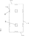
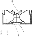
- Figures 1-5 each show an embodiment of the building block 1 according to the present invention.
- the building block has a top surface 10, a bottom surface 11, a first short side surface 12 and a second short side surface 13, both side surfaces preferably being parallel, a first long side surface 14 and a second long side surface 15, both long side surfaces preferably being parallel.
- the block 1 is shown rectangular in horizontal cross-section, the shape is not limited there to but can include square or hexagonal.
- the building block is completely filled, i.e. is a massive solid material (not shown).
- the interior of the building block 1 is preferably hollow, having a plurality of interior cavities 20.
- Said plurality of interior cavities 20 are preferably mutually partitioned by strengthening elements 21, the purpose of which is to enhance the rigidity of the structure of the building block 1.
- Said strengthening elements 21 can have at least partially a planar shape, arcuate or a rounded shape.
- the strengthening elements 21 are preferably made in the same material as the sides of the building block 1 and form one piece with it.
- said strengthening elements can be shaped so as to allow the insertion of a tubular-shaped element (not shown in the figures) in a cavity of said plurality of interior cavities 20.
- the strengthening elements 21 provide at least one cavity having a diameter of at least 90mm, which typically corresponds with the diameter of water drainage.
- the strengthening elements 21 can provide a plurality of cavities which can be configured for specific architectural elements such as water pipes, electricity cable, telecommunications cable, heating or cooling pipes, gas pipes, fibre optical cables etc.
- FIG. 6a An example of a building block arranged with a tubular element is shown in Figure 6a and 6b .
- Figure 6a shows that a hole is drilled in a side surface of the building block 1.
- the tube can then be installed through said hole in a cavity of said plurality of interior cavities 20 as indicated in Figure 6b .
- the cavities of said plurality 20 can be filled with isolation material (not shown in the figures).
- the cavities are preferably filled with a material that is easy removable and that can be used for a subsequent construction or for another application.
- Said isolation material can be, for example cellular insulation, comprising glass, plastic or rubber; fibrous insulation, such as glass fibers, rock wool, slag wool or alumina silica; flake insulation, such as vermiculite; or granular insulation, such as expanded polymers such as expanded polystyrene (EPS).
- the isolation material comprises EPS.
- the filling materials can be provided to improve the acoustic damping of the block.
- the building block 1 can be made in a wide variety of sizes.
- the building blocks 1 will have a size similar to the dimensions of standard stones or concrete bricks that are used for the construction of traditional housing.
- the building block 1 can have a width that is at least 10 cm, preferably at least 15cm, more preferably at least 20 cm, and most preferably at least 25 cm.
- the building block 1 will usually have a width up to 50cm.
- the building block 1 will have a width of around 30cm, p.
- the width can be increased up to the maximum size that can be manufactured such as up to 1 metre.
- the width is in the range 30cm to 80 cm.
- the building block 1 will have a length that is up to 100cm, preferably up to 90cm, more preferably up to 80cm, and most preferably up to 70cm.
- the building block 1 will have a length that is at least 20cm, typically at least 30 cm.
- the length of the building block 1 advantageously is twice or about twice the width of the length. This allows a swift combination of building blocks for construction as will be described here below
- the building block 1 will have a height that is up to 70cm, preferably at most 60cm, more preferably at most 50cm and most preferably at most 40cm.
- the minimum height can be 15cm, or 20 cm or 30 cm, for example
- the side surfaces 12-15 can be planar.
- at least one side surface 12-15 is provided with an interconnecting means 30 for connecting the block sideways to an adjacent block.
- Said interconnecting means 30 can include a protrusion or groove.
- a groove is preferred in all embodiments of the present invention.
- the protrusion or groove preferably has a shape that provides part of a form closure between blocks, such as a tongue-and-groove connection.
- said interconnecting means 30 is a groove extending perpendicularly to the top surface 10, i.e. being a vertical or substantially vertical groove in the side surface when installed.
- the groove can have any geometric form in cross-section, for example including square, triangular or rectangular elements. It is preferred if the groove has a shape that provides part of a form closure between blocks. In particular the groove has a shape that provides part of a 2D form closure between blocks (including blocking rotation) whereby in the third dimension an elongate element with an outer surface matching the internal surface of the groove may slide in the groove.
- matching is meant that preferably the interconnecting means sheaths the elongate element i.e. the elongate element is a snug fit in the interconnecting means but can slide therein.
- the outer surface of the elongate element is preferably the inverse shape of the inner surface of the interconnecting means.
- Figure 5 shows an embodiment wherein the groove has a T-shape.
- the groove has the form which corresponds to the half of a plus sign (+).
- the groove has a trapezoidal shape in cross-section.
- a groove according to this preferred embodiment is herein after referred to as a dovetail groove.
- dovetail grooves as interconnecting means 30.
- the interconnecting means 30 are suitable for a 2D form closure connection (including blocking rotation) between blocks with the ability to slide in the third dimension, i.e. along the groove.
- the dovetail, or T grooves are both suitable for a 2D form closure but allow sliding in the third dimension, i.e. along the groove.
- the first and the second short side surface 12,13 each have at least one dovetail groove, with the purpose of interconnecting adjacent building blocks 1.
- the first and the second short side surface 12,13 each have one dovetail groove.
- the first and second long side surfaces 14,15 each have at least one dovetail groove for similar purposes.
- the long side surfaces 14,15 each have two dovetail grooves.
- the dovetail grooves are provided on the side surfaces 12-15 in such a way that two building blocks 1, placed adjacently for building a wall according to this invention, will have at least one of their respective dovetail grooves in a corresponding position, allowing to interconnect both building blocks by use of a first complementary element 40 which is the elongate element mentioned above.
- the first complementary element 40 in combination with the groove provide a 2D form closure with the first complementary element 40 being slidable in the third dimension, i.e. along the groove.
- the interconnecting means preferably sheaths the first complementary element i.e. the first complementary element is a snug fit in the interconnecting means but can slide therein.
- the outer surface of the first complementary element is preferably the inverse shape of the inner surface of the interconnecting means.
- the first complementary element can assume only one position in the interconnecting means. The double dovetail allows two possible positions for insertion in the interconnecting means however the result is the same in both cases.
- a first complementary element 40 is used for interconnecting two adjacent building blocks 1, by inserting the first complementary element 40 in the respective dovetail grooves of the two adjacent building blocks 1.
- An example of such an arrangement is shown in Figure 7 , where it is clear that the element 40 fits the volume that is formed by the grooves when the blocks 1 are placed against each other.
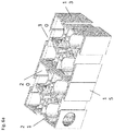
- a perspective view showing how the insertion of the first complementary element 40 interconnects two adjacent blocks can be found in Figure 8 . It is an advantage of the present invention that by laying the building blocks 1 in a series of rows according to the method of the present invention, interconnecting means 30 can be provided suitable for a 2D form closure connection between blocks with the ability to slide in the third dimension.
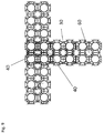
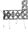
- Figure 9 shows a wall constructed with building blocks 1 according to the invention, wherein the blocks are combined to form a corner.
- a block can also be cut in half laterally, a top view of such a block according to an embodiment is shown in Figure 10a , or a quarter of a block can be cut transversally, a top view of such a block is shown in Figure 10b , and the pieces obtained can be combined in a row with complete building blocks. This can be done to locally complete a gap in a construction, thereby guaranteeing sufficient thermal isolation in all parts of the construction.
- Figure 11 An example of such an arrangement, combining a full block with half a block is shown in Figure 11 .
- said first complementary element 40 can be used to interconnect building blocks 1 vertically. Indeed, when laying series of rows, one row on top of another, according to the invention, interconnecting means such as dovetail grooves of one particular block, an underlying block and an upper block to this particular block, can be situated in a corresponding position, allowing to insert said first complementary element in these interconnecting means such as dovetail grooves, linking the particular block with its underlying and upper counterparts.
- the vertically placed first complementary element 40 provides minimum support for surviving tension in the wall e.g. during seismic activity, e.g. after shocks.
- the first complementary element 40 When connecting adjacent blocks in the same row as well as blocks in rows that are on top of one another, the first complementary element 40 will take a rod-shaped form.
- the first complementary element 40 is preferably made from a rigid material.
- the first complementary element 40 is made from a plastic or a plastic composite, wood or any other material that allows the element to be easily sawn lengthwise or crosswise.
- said first complementary element is made from the same material as the building block.
- the first complementary element 40 has a shape that is complementary to the shape of the interconnecting means 30 of the blocks it is interconnecting.
- the first complementary element 40 will have a shape that is double trapezoidal in cross-section, as it is complementary to two opposing dovetail grooves.
- a first complementary element 40 having such a shape will be referred herein after to as a double dovetail shape.
- the first complementary element will be further referred to as a double dovetail rod. A representation of such a double dovetail rod is shown in Figure 12 .
- sealing 50 is provided along the length of the first complementary element such as the double dovetail rod.
- said sealing 50 is a sealing strip based on a rubber or elastomer.
- the sealing 50 is for sealing between the first complementary element and the interconnecting means 30 i.e. the groove.
- the seal 50 extends over the complete length of the interconnecting means and the first complementary element when the first complementary element is installed.
- the sealing 50 and a gasket between the top of one block and the bottom of the block immediately above makes a wall made with the blocks water tight or with little leakage.
- the sealing 50 and the gasket avoid the use of mortar such that a wall produced with the blocks is mortarless.
- the double dovetail rod is provided with four sealing strips.
- the sealing strips have the advantage that they avoid water seeping through the interconnection of the blocks while still allowing insertion of the rod.
- the sealing strips avoid water seeping from one side of the wall to another such as from the outside to the inside of a house, from a swimming pool to the surrounding earth, through a dam or weir.
- the sealing strips help to append the double dovetail rod to the building blocks.
- the building block 1 has at least one vertical or substantially vertical hole 60, extending from the top surface 10 to the bottom surface 11.
- the at least one hole 60 can have in cross-section of any geometric shape, including round, triangular, or rectangular elements. Particular to the shape of the hole 60 is that it is preferably interconnected to and co-defined by the shape of the first complementary element 40, in that said first complementary element 40 should fit in the hole 60.
- the first complementary element 40 in combination with the shaped hole 60 preferably provides a 2D form closure between blocks (including blocking rotation) with the first complementary element 40 being slidable in the third dimension, i.e. along the hole.
- cutting the block 1 in half laterally, or cutting a quarter of the block 1 transversally can result in a hole 60 in the block 1 to be divided among the obtained pieces.
- the geometrical shape of the hole should then be such that the piece can be interconnected with an interconnecting means 30 of another block 1 by use of a first complementary element 40, i.e. providing a 2D form closure with the first complementary element 40 being slidable in the third dimension, i.e. along the hole.
- the first complementary element 40 can take up a limited number of positions in the hole 60.
- the geometrical features of the interconnecting means 30 will therefore have a similarity with the geometrical shape of the hole 60, i.e. the interconnecting means 30 will have the same geometrical shape of the hole 60 and the first complementary element 40 will have the complementary inverse geometrical shape of the hole 60.
- the embodiment shown in Figure 4 has i.e. two holes 60 having the cross-sectional shape of a plus sign, the interconnecting means 30 being the half of a plus sign.
- the building block according to the embodiments as shown in Figure 1-3 is provided with two holes 60 having a star-like shape in cross-section.
- Said shape comprises two double dovetails with a mutual angle of 90° and will be referred herein after to as a star shape.
- Figures 10a-10b show, cutting the block as described hereabove, allows for the obtained pieces to be interconnected with other blocks, as the remaining part of the hole 60 can house a double dovetail rod.
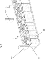
- a second complementary element 70 can be used for vertically connecting building blocks 1 that are stacked on top of one another by inserting said second complementary element 70 vertically in a hole 60 of each of the interconnecting stacked building blocks 1.
- the second complementary element 70 can be sheathed by the hole 60 when inserted, i.e. the second complementary element is a snug fit in the hole but can slide therein.
- the outer surface of the second element is preferably the inverse shape of the inner surface of the hole.
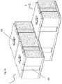
- Figure 13 shows a stack of blocks 1 arranged according to this embodiment of the present invention, wherein a second complementary element 70 is vertically inserted through holes 60 of said vertically stacked building blocks 1.
- the building blocks 1 according to the invention are thereby preferably stacked in such a way that the holes 60 of the blocks 1 are situated in extension of each other, allowing the insertion of said second complementary element 70.
- the advantage of using said second complementary element 70 is that stacked building blocks 1 can be securely held together, thereby making the need for additional elements such as nails or screws superfluous.
- the second complementary element 70 in combination with the shaped hole 60 preferably provides a 2D form closure (including blocking rotation) with the second complementary element 40 being slidable in the third dimension, i.e. along the hole.
- the second complementary element 70 has a rod-like shape.
- the cross-sectional shape of the second complementary element 70 is complementary to the cross-sectional shape of the holes of the building blocks, i.e. the second complementary element 70 will have the complementary inverse geometrical shape of the hole 60. If the holes have a star shape, as defined here above, the second complementary element will be complementary to this shape. Without limiting the invention, the second complementary element will be further referred to as a star-shaped rod. A representation of such a star-shaped rod is shown in Figure 13 .
- sealing 50 is provided along the length of the star-shaped rod.
- said sealing 50 is a sealing strip based on a rubber.
- the star-shaped rod is provided with eight sealing strips, the aim of which is to avoid water seeping through.
- the star-shaped rod as well as the dovetail rod can be sawed to the desired length.
- first and second complementary elements having an interconnected or complementary shape such as double dovetail rods and star rods, allow for the rapid and easy build-up of walls for temporary housing, wherein said walls meet all requirements regarding stability and bearing capacity.
- the top surface 10 and the bottom surface 11 of said building block 1 can be open.
- Stacking open blocks has the advantage that isolation and/or acoustic damping material can be added into a wall after construction has been finished or during construction.
- ducts and tubes are easy to install in a wall with open blocks, due to the fact that such a stack, having cavities of each block lying in the extension of one another, can result in open spaces that extend from the floor level to the top level of the wall in which ducts and tubes can be inserted.
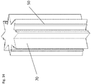
- top surface 10 is a closed surface, an example of which is shown in Figure 15 .
- a building block 1 with a closed top surface 10 can be used for constructing a complete wall.
- a building block 1 according to this alternative embodiment will be used in the arrangement of a top layer of a wall, the other blocks in the wall being blocks with an open top surface, thereby closing off the constructed wall and any isolation material therein.
- the bottom surface 11 is a closed surface.
- a building block 1 having a closed bottom surface 11 can be used as part of a bottom layer of building blocks on top of which the wall is erected.
- the top part of the building block 1 can be made raised and slightly narrower than the bottom of the building block 1 (forming a shoulder around the periphery of the upper surface), so that the narrower top part of a first building block fits or slots into a wider recessed bottom part of a second block that is placed on top of said first building block. This can be done by indenting the ledge of the top part of the building block 1 and by widening the ledge of the bottom part of the block 1.
- FIG. 16 An alternative embodiment is shown in Figure 16 , wherein the building block is provided with vertical extensions on both the top and bottom surface 10-11.
- said vertical extensions are provided either on the top surface or on the bottom surface, allowing two superposed blocks to fit.
- a gas or water sealing 50 can be provided on the building block 1, preferably encircling at least partially the building block 1 on the side.
- An example of such a sealing 50 is shown in Figure 17 .
- a sealing 50 can be placed on the inside of an indented ledge forming a sealing gasket between an upper and lower block when stacked.
- a sealing 50 encircling the building block will be arranged on the inside of the building block 1, at the bottom part of the block, where the sealing 50 can be arranged in a ledge.
- the advantage of placing the sealing 50 in this ledge is that stacking the block on top of another block will make the interconnection waterproof (in conjunction with the sealing strips along the first complementary element) and prevent or reduce water penetration.
- any of the sealings 50 are preferably a rubber-based or elastomer-based sealing.
- a wall made using blocks 1 of any of the embodiments of the present invention is sealed and mortarless when the sealings 50 are in place.
- the sealing 50 can be omitted when a wall made using blocks 1 has no need for being water sealing. This can be the case when a wall is built with the purpose of diverting water. The water sealing requirements of e.g. a dam built by said blocks can therefore be less stringent than when the blocks are used for the construction of housing.
- the building block 1 can be made from a material that ensures an acceptable degree of mechanical rigidity, enabling the building block 1 to bear at least the load of the wall and a roof.
- a wall made using blocks 1 of any of the embodiments of the present invention can be load-bearing.
- the building block 1 can further be weatherproof and UV-resistant.
- construction workers can cut the material of the block 1 without the need for advanced machines.
- the material preferably has a thermal conductivity k that is acceptably low.
- the material of the building block 1 should also be insect-resistant and resist insects such as termites.
- the building block 1 can be made from a material that is chosen from the group consisting of wood, metal, mineral materials, concrete, ceramic materials such as glass, or plastic-based materials.
- the building block 1 can be made as a composite of said materials, wherein some components can be present as fillers or fibres.
- the building block 1 is a composite material, comprising a plastic material and a mineral additive and/or a powder made of a cross-linked thermoset polymer.
- the composite material comprises at least 60wt%, preferably at least 65wt%, more preferably at least 70wt% and most preferably at least 75wt% of said plastic material, with reference to the total weight of the composite material. It is further understood that the composite material comprises at most 95wt%, preferably at most 90wt%, and more preferably at most 85wt% of said plastic material, with reference to the total weight of the composite material.
- a first part of the plastic material can be a recycled plastic material that is recovered from a plastic waste stream.
- a second part of the plastic material can comprise new plastic material, meaning material that is polymerized from raw materials for use in said plastic material. From an ecological point of view, making the building block 1 at least partly from waste stream plastic material has the advantage of relieving the burden on the consumption of natural resources.
- the plastic material can comprise at least 50 wt%, preferably at least 60 wt%, more preferably at least 70 wt%, even more preferably at least 80 wt% and most preferably at least 90 wt% of said recycled plastic material recovered from a waste stream, with reference to the total weight of the plastic material.
- the remaining part of the plastic material consists preferably of said new plastic material.
- the plastic material comprises only recycled plastic material.
- the plastic material can be a thermoplastic material.
- the plastic material comprises poly vinyl chloride polymer (PVC) or copolymer.
- PVC is self-extinguishing.
- PVC can be used for the blocks according to any of the embodiments of the present invention, so that the building materials provided by any of the embodiments of the present invention can be self-extinguishing.
- PVC has a density of 1.35 to 1.45 g/cm 2 .
- PVC can be used for the blocks according to any of the embodiments of the present invention, so that the building materials provided by any of the embodiments of the present invention are heavier than water.
- the PVC is foamed.
- the composite material can further comprise a mineral additive.
- the composite material consists only of said plastic material and said mineral additive.
- the mineral additive is typically used in powder or flake form.
- Mohs scale of hardness is a known and often used classification for mineral hardness.
- the mineral additive preferably has a hardness of 6 or less on Mohs scale of mineral hardness.
- the mineral additive has a hardness of 3 or more on Mohs scale of mineral hardness.
- the additive is based on material from the Carboniferous Limestone Group, or minerals comprising: CaMg (CO 3 ) 2 , SiO 2 , FeS 2 , CaF 2 and/or CaCO 3 .
- the mineral additive comprises bluestone.
- a soft marble species can be used.
- PVC is self-extinguishing.
- PVC with a mineral additive can be used for the blocks according to any of the embodiments of the present invention, so that the building materials provided by any of the embodiments of the present invention can be self-extinguishing.
- the building block 1 can be produced by use of typical processing techniques for plastic composite materials, including injection moulding, rotation moulding, extrusion and 3D printing techniques.
- the building block is foamed.
- the building block 1 is made from a material having a Young's modulus E, measured according to ISO 527-2:2012, which is at least 4200 MPa, preferably at least 4400 MPa, more preferably at least 4600 MPa, even more preferably at least 4800 MPa, more preferably at least 5000 MPa, even more preferably at least 5200 MPa, more preferably at least 5400 MPa, even more preferably at least 5600 MPa and most preferably at least 5800 MPa.
- a Young's modulus E measured according to ISO 527-2:2012, which is at least 4200 MPa, preferably at least 4400 MPa, more preferably at least 4600 MPa, even more preferably at least 4800 MPa, more preferably at least 5000 MPa, even more preferably at least 5200 MPa, more preferably at least 5400 MPa, even more preferably at least 5600 MPa and most preferably at least 5800 MPa.
- the building block 1 is made from a composite material as described here above, having a Young's modulus E which is at least 4200 MPa, preferably at least 4400 MPa, more preferably at least 4600 MPa, even more preferably at least 4800 MPa, more preferably at least 5000 MPa, even more preferably at least 5200 MPa, more preferably at least 5400 MPa, even more preferably at least 5600 MPa and most preferably at least 5800 MPa.
- a Young's modulus E which is at least 4200 MPa, preferably at least 4400 MPa, more preferably at least 4600 MPa, even more preferably at least 4800 MPa, more preferably at least 5000 MPa, even more preferably at least 5200 MPa, more preferably at least 5400 MPa, even more preferably at least 5600 MPa and most preferably at least 5800 MPa.
- a method for building a mortarless demountable load-bearing wall by use of building blocks 1 according to any of the embodiments of the present invention.
- trenches can be dug in a first step according to a planned position of the wall or walls.
- Plastic foils and plates can be provided for blocking groundwater.
- a first row of building blocks 1 is then installed in said trench and the trench is filled up at least partially with concrete, preferably leaving the top part of the row building blocks 1 visible to allow further building on top of said row.
- the first step consists of placing said first row of building blocks 1 on the ground according to the planned position of the walls.
- a form of anchorage is provided for anchoring said row to the ground.
- Building blocks 1 can be combined with cut parts of other blocks, as described here above, to obtain the desired shape.
- a second row of building blocks 1 can be placed on top of said first row of building blocks 1.
- the blocks are shifted 50%, or half a length of a block, with respect to the underlying blocks.
- each individual block of said second row is placed on top of an individual block of the underlying row.
- the building blocks 1 are interconnected horizontally, meaning within the same row, and vertically by said first and second complementary elements.
- said elements can be inserted vertically in holes and/or interconnecting means of a plurality of blocks, thereby interconnecting this plurality of blocks.
- a high degree of freedom is given to the user or construction worker to decide the length of each complementary element.
- the user can i.e. choose to interconnect stapled blocks belonging to a series of rows with a limited amount of long complementary elements.
- the complementary elements can be sawn to a desired length, with the purpose of interconnecting fewer blocks.
- the cavities in the building blocks, which are interconnected can be filled by use of a granular inert material with the purpose of thermally isolate the building the blocks are part of, e.g. to provide thermal isolation or acoustic damping.
- a granular inert material with the purpose of thermally isolate the building the blocks are part of, e.g. to provide thermal isolation or acoustic damping.
- This can be done by pouring said granular inert material in the open top surface 10 of the highest blocks in the constructed wall.
- two elements contribute to thermal insulation or acoustic damping: the granular inert material as well as the air that is permanently trapped in the other cavities 20.
- the building block according to any of the embodiments of the present invention are furthermore provided for the construction of an interior wall.
- building blocks 1 can be used for the interior walls, wherein the blocks making up the interior wall can form an angle of 90° with respect to an exterior wall, as described here above.
- the advantage of using the same blocks for the interior and exterior walls is that only one type of block is necessary for the construction of all the walls.
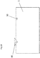
- an interior building block 100 is used, embodiments of which are shown in Figure 18 .
- the interior building blocks 100 are typically more elongated and less wide compared to the building block 1.
- the interior building blocks 100 can be interconnected with building blocks 1 forming an exterior wall, forming an angle of 90° therewith, by use of said first complementary element such as a double dovetail rod.
- the principle for an alternative mechanism for interconnecting the blocks is shown in figure 19 , showing a top view, wherein said building block 1 is provided with an interconnecting means 30, which has a cross-section having a rounded shape, such as a rounded groove. Consequently, the first complementary element 40 is arranged to fit in both the interconnecting means 30, having said rounded groove, and interconnecting means 30 of the interior building block, having for example a trapezoidal cross-section (not shown in Figure 19 ).
- a specific application of said building block 1 according to any of the embodiments of the present invention is the construction of wall to divert the course of water, to provide a weir wall or a dam wall according to a further embodiment of the present invention. Even when water is present the wall can be constructed as all materials are waterproof. This even allows walls to be installed under water e.g. by divers.
Landscapes
- Engineering & Computer Science (AREA)
- Architecture (AREA)
- Civil Engineering (AREA)
- Structural Engineering (AREA)
- Physics & Mathematics (AREA)
- Electromagnetism (AREA)
- Building Environments (AREA)
Abstract
Description
- The present invention relates to a building block for use in the construction of building structures such as walls, more in particular a building block for use in the building of housing, such as temporary or emergency housing or weirs, dams as well as to the building structures such as walls, more in particular housing, such as temporary or emergency housing or weirs, dams themselves. The invention also relates to a method for use in same.
- Disasters can be natural or manmade, the frequency of which may increase in the near future due to climate change, which are some of the known reasons why people are forced to leave their homes to seek safe shelter. Temporary shelter is often provided to these people in the form of tents, containers or temporary housing such as portable modular buildings. The latter has the advantage that the building parts are usually easier to transport than containers, and they provide a better shelter from weather conditions than tents. Temporary housing can be built by stacking lightweight building blocks.
- Tents are well known to the skilled person. Portable modular buildings are often used as temporary site offices on building sites where they can be stacked two high with metal stairs to reach the upper level. Other uses for these and other types of portable buildings are as guard posts, in-plant offices, rural offices, on-site changing rooms, etc. Some portable buildings are very complex and by joining units can be formed into large office blocks. Disused containers can also be used to make temporary accommodation. The temporary shelter in Kilis, Turkey has been described as a perfect refugee camp with 2,053 identical containers spread out in neat rows. The containers are customised, e.g. provided with power and water. Each 7m-by-3m container trailer has three rooms, with a lockable front door. A bathroom is serviced by its own plumbing and hot-water tank; a kitchen is equipped with both a refrigerator and a stove. There is a living room, and television reception is possible e.g. by satellite TV.
- In order to provide comprehensive fast response temporary housing supply centres, the building materials should ideally be
- a) Compact rather than including a large amount of bulky air space
- b) Of low added value such as that high value products are not stored
- c) Can be used in a wide variety of situations to provide a wide variety of different structures as it is never certain what the next disaster can be, such as an earthquake, a flood, a tornado or hurricane, the influx of refugees fleeing a war zone for example
- d) Be easily transportable
- e) Be easily assembled on site with as few as possible additional accessories like nuts and bolts
- f) Be demountable after installation for re-use
- g) Be made of materials that are self-extinguishing, cheap to produce and capable of producing load-bearing structures.
- Patent application
US 2008/0184649 discloses an interlocking stackable modular building block for making barriers, slabs and emergency living quarters. The block is a hollow container that can be placed adjacent to another block in an interlocking position by inserting a tongue on the one end of the block into a groove of the adjacent block. Blocks have a narrow ledge on the top and a wider extension on the bottom. The extension on the bottom fits the top of the narrow ledge when blocks are placed on top of each other, wherein both blocks are further held together with screws. - The building block as disclosed in
US2008/0184649 has the disadvantage that it is difficult to use in creating corners. Furthermore, screws are needed to secure two blocks stacked one top of each other. Small building parts such as screws are however difficult and time consuming to use in emergency situations. - Embodiments of the present invention relate to a building block for use in a wide variety of applications such as being suitable for the quick and easy construction of a wall, whereby the wall can be part of an architectural structure such as a house, a house extension such as a garage or a garden shed, an inner wall, especially a movable inner wall, a temporary house or a weir, or a dam, wherein the block can be adapted to build corners. The building block can be lightweight, easy to manipulate in difficult environmental conditions and thermally isolating and protects against ingress by vermin or predators such as wolves, rats or snakes and gives also some protection against human intruders. The constructions that can be built with the blocks can be weather resistant, easy and quick to build, with a minimum of training, parts and equipment.
- In comparison with the three main types of materials commonly used in emergency situations such as tents, portable modular building and modified containers, embodiments of the present invention have some or all of the following advantages:
- a) Stored in a compact form - not storing of large volume of "air" - this provides an advantage over containers
- b) Basic building blocks are stored - low added value products are stored - this provides an advantage over modular buildings and customised containers which are high value-added products
- c) Demountable and reusable - this provides an advantage over brick and mortar - removal of mortar usually takes a long time
- d) Flexible in design of buildings - this provides an advantage over modular buildings and containers which have fixed predefined shape
- e) Easy and quick to assemble - this provides an advantage over "raw" containers that have to be customized and metal framed portable buildings that require lots of nuts and bolts
- f) Do not require hand applied mortar - this provides an advantage over bricks and mortar
- g) Can be made locally by technically simple methods - this provides an advantage over modular buildings which are high value-added products typically made with complex manufacturing techniques in high tech countries
- h) Light weight - density of the material can be 1.35 -1.45 g/cm2 which is reduced by air space in the block - this provides an advantage over containers and brick and mortar
- i) Blocks and the building are thermally insulated against hot/cold without need for additional materials/cladding - this provides an advantage over tents and containers
- j) Mechanical protection, e.g. from wolves, rats, dogs, human intruders - this provides an advantage over tents
- k) Can make walls that are water sealed immediately after installation, e.g. weirs or dams, or swimming pool walls - this provides an advantage over tents and brick and mortar with which mortar must set before wall is water tight. This provides an advantage over containers and modular buildings which cannot be used to make walls easily
- l) Can be used to make toilet/shower/bathroom buildings (ablutions) which are easy to keep clean. This provides an advantage over tents
- m) Material can be self-extinguishing. This provides an advantage over tents
- n) Buildings meet at least basic seismic resistance requirements (e.g. after shocks) as the walls can withstand both tension and compression due to vertical support elements
- o) Can be used to make inner walls in existing buildings. This provides an advantage over containers, tents.
- p) Can be used to make demountable or movable inner walls in existing buildings - this provides an advantage over containers, tents and brick and mortar.
- q) Can be used to make walls with standard windows - this provides an advantage over tents, and raw containers.
- r) Storage space such as shelving and cupboards and other objects can be fixed to the wall. - this provides an advantage over tents
- s) Walls can be load bearing. - this provides an advantage over tents
- t) Walls can be installed underwater by divers - this provides an advantage over tents, brick and mortar.
- u) No severe reduction in wireless communication reception quality (no metal Faraday cage) - this provides an advantage over containers
- v) Walls can provide acoustic damping - this provides an advantage over containers, tents.
- w) As the blocks can be used for many different applications and are economical to produce, the blocks are suitable for storing in depots ready for use in any of a variety of emergency situations generated by manmade or natural disasters - this provides an advantage over containers and modular buildings which are expensive to make and/or store.
- According to an aspect of the present invention, there is provided a load-bearing building block for building mortarless demountable load-bearing walls, the building block comprising:
- interconnecting means in at least one side surface of the building block for interconnecting the block adjacent to its side surface, with the interconnecting means of a similar block by use of a first complementary element, wherein said interconnecting means comprise a groove and the first complementary element is slidable in a first dimension along the groove and has a two-dimensional form closure when installed in the groove;
- at least one vertical hole, extending from the top to the bottom surface of the block; wherein said at least one hole is vertically interconnectable with the at least one hole of a similar block, positioned above or below, by use of said first complementary element, the first complementary element being slidable in the first dimension through the hole and has two-dimensional form closure when installed in the hole.
- According to an aspect of the present invention, there is provided a load-bearing building block for building mortarless demountable load-bearing walls, the building block comprising:
- interconnecting means in at least one side surface of the building block for interconnecting the block adjacent to its side surface, with the interconnecting means of a similar block by use of a first complementary element, wherein said interconnecting means comprise a groove and the first complementary element is slidable in a first dimension along the groove and has a two-dimensional form closure when installed in the groove, wherein interconnecting means of adjacent building blocks forming a corner are situated in front of one another;
- at least one vertical hole, extending from the top to the bottom surface of the block; wherein said at least one hole is vertically interconnectable with the at least one hole of a similar block, positioned above or below, by use of said first complementary element, the first complementary element being slidable in the first dimension through the hole and has two-dimensional form closure when installed in the hole,
wherein the combination of said building blocks and said first complementary element allow the build-up of said wall, whereby said wall is part of an architectural structure. - It is an advantage of the present invention that a mortarless demountable load-bearing wall can be constructed by use of the building blocks according to the present invention, with a limited amount of building parts and without any need of advanced construction techniques. The walls are demountable, so that the building parts such as building blocks and any complementary elements can be stocked in a compact form. As these parts are basic parts with low-added value, they can be stocked locally, meaning near areas of possible flooding. The building blocks are used to build a mortarless wall, having the advantage that the parts can be assembled rapidly, also in areas where the presence of water would impede the construction of traditional mortar-containing walls. The building blocks, when used for building temporary housing in emergency situations, have as additional advantage that it offers more protection than tents against the elements as well as security against possible intruders, or animals such as vermin. Due to the load-bearing capacities, the building blocks and walls can resist tension and compression, offering safer housing.
- In an embodiment of the present invention, the building block has a first complementary element which is elongate and has a longitudinal seal. The first complementary element co-operates with the interconnecting means so that the longitudinal seal seals against the interconnecting means when the first complementary element is installed in the interconnecting means.
- It is an advantage of this embodiment that a construction built by use of said building blocks can be made water sealing. It is a further advantage that the construction is water sealing directly after installation, as there is no mortar that has to set.
- In an embodiment of the present invention, the first complementary element is sheathed by the interconnecting means when the first complementary element is installed in the interconnecting means.
- It is an advantage of this embodiment that a stable and water sealing installation can be obtained, without a need for any additional elements such as bolts or rivets.
- In an embodiment of the present invention, the first complementary element takes up a single unique functional position in the interconnecting means when the first complementary element is installed in the interconnecting means.
- It is an advantage of this embodiment that construction workers do not need an extensive training, as they can easily assemble the building parts, including the blocks and any complementary parts, into a construction.
- In an embodiment of the present invention, the first complementary element can take up more than one functional position in the hole when the first complementary element is installed in the hole or the first complementary element can take up a limited number of functional positions in the hole when the first complementary element is installed in the hole.
- It is an advantage of this embodiment that this adds to stability of the construction as well as to user-friendliness for possibly poorly trained local construction workers.
- In an embodiment of the present invention, the interior of the building block is hollow, said hollow block having a plurality of interior cavities.
- It is an advantage of this embodiment that the basic building part - the building block - can be made lightweight which facilitates transport.
- In an embodiment of the present invention, said plurality of interior cavities is formed by strengthening elements for enhancing the rigidity of the building block.
- In an embodiment of the present invention, a tubular element such as a pipe or conductor is insertable in at least one of said plurality of interior cavities.
- It is an advantage of this embodiment that utility ducts and pipes can be provided in the walls of housing built with said building blocks - even temporary housing - so that utilities such as electricity and water can be provided to habitants, which is an advantage over the use of tents.
- In an embodiment of the present invention, said plurality of interior cavities are at least partially filled with a thermal isolation and/or acoustic damping material.
- It is an advantage of this embodiment that habitants of housing built with said building blocks are shielded against heat or cold.
- In an embodiment of the present invention, the length of the building block is twice or about twice the width of the block.
- It is an advantage of this embodiment that building blocks can be easily combined in a construction with desired shape, which can be built by possibly poorly trained construction workers.
- In an embodiment of the present invention, said interconnecting means comprise a groove having a trapezoidal, dovetail shape in cross-section.
- It is an advantage of this embodiment that said interconnecting means allows the building block to be interconnected by form closure.
- In an embodiment of the present invention, said block is made from a material, selected from the group comprising a thermopolymer and a thermosetting polymer.
- In an embodiment of the present invention, the building block is made from a composite material comprising recycled plastic material and a mineral additive with a hardness of 6 or less on Mohs scale of mineral hardness.
- It is an advantage of this embodiment that the building block can be lightweight and resistant. As it is partially made from recycled material, it decreases a burden on raw resources.
- In an embodiment of the present invention, said mineral additive has a hardness of 3 or more on Mohs scale of mineral hardness.
- In an embodiment of the present invention, said mineral additive comprises bluestone.
- In an embodiment of the present invention, said recycled plastic material comprises a thermoplastic polymer.
- In an embodiment of the present invention, said thermoplastic polymer is poly vinyl chloride (PVC).
- In an embodiment of the present invention, said recycled plastic material comprises at least 50 wt%, preferably at least 60 wt%, more preferably at least 70 wt%, even more preferably at least 80 wt% and most preferably at least 90 wt% plastic material recycled from a waste stream.
- In an embodiment of the present invention, said recycled plastic material further comprises powered thermoset material.
- In an embodiment of the present invention, the building block further comprises a gasket which seals between an upper surface of one block and the lower surface of a second block placed on the first block.
- It is an advantage of this embodiment that a construction can be obtained which is water sealing. This is useful for the construction of temporary housing in areas experiencing a flood, or for applying the building blocks in the construction of a weir or a dam.
- In an embodiment of the present invention, the first complementary element comprises a second complementary element, wherein said at least one hole is vertically interconnectable with the at least one hole of a similar block, positioned above or below, by use of said second complementary element, the second complementary element being slidable in the first dimension through the hole and has two dimensional form closure when installed in the hole, the second complementary element being sheathed by the hole when the second complementary element is installed in the hole, or the second complementary element have a unique functional position when the second complementary element is installed in the hole.
- According to an aspect of the present invention, there is provided a kit of parts of a plurality of blocks and a plurality of first complementary elements for interconnecting the interconnecting means of a building first block with the interconnecting means of a second block placed adjacent to a side surface and/or the top surface of the first block.
- In an embodiment of the present invention, each first complementary element of the kit of parts has a double trapezoidal shape in cross-section.
- In an embodiment of the present invention, some of the first complementary elements of the kit of parts are second complementary elements.
- According to an aspect of the present invention, there is provided a mortarless demountable load-bearing wall made with a plurality of blocks.
- According to an aspect of the present invention, there is provided a method for constructing a mortarless demountable load-bearing wall, by use of building blocks, comprising installing a first row of building blocks,
Installing a second row of building blocks on top of said first row of building blocks, Interconnecting the building blocks horizontally within the same row by installing said first complementary elements, and vertically by installing said first complementary elements or first and second complementary elements. - In an embodiment of the present invention, the method further comprises filling cavities in the blocks with a granular inert material to thermally isolate the building constructed by use of the blocks or to provide acoustic damping.
- These and other features and advantages of embodiments of the present invention will now be described in more detail with reference to the accompanying drawings, in which:
-
Figures 1a and1b schematically illustrate a building block according to an embodiment of the invention; -
Figure 2 schematically illustrates the building block according to another embodiment of the invention; -
Figure 3 schematically illustrates the building block according to another embodiment of the invention; -
Figure 4 schematically illustrates the building block according to another embodiment of the invention; -
Figure 5 schematically illustrates the building block according to another embodiment of the invention; -
Figures 6a and6b schematically illustrate the arrangement of a tubular element according to an embodiment of the invention; -
Figure 7 shows a top view of an arrangement for interconnecting two adjacent building blocks according to an embodiment of the invention; -
Figure 8 shows a perspective view of an arrangement for interconnecting two adjacent building blocks according to an embodiment of the invention; -
Figure 9 shows a top view of a corner arrangement according to an embodiment of the invention; -
Figures 10a and10b show a top view of a building block according to an embodiment of the invention, wherein the block is respectively cut in half laterally, or wherein a quarter of the block is cut transversally; -
Figure 11 shows a top view of an arrangement, interconnecting a full block with half a block; -
Figure 12 shows a perspective view of a first complementary element according to an embodiment of the invention; -
Figure 13 shows a perspective view of a stack of building blocks according to an embodiment of the invention; -
Figure 14 shows a perspective view of a second complementary element according to an embodiment of the invention; -
Figure 15 shows a perspective view of an arrangement of building blocks having a closed surface for top surface according to an embodiment of the invention; -
Figure 16 shows a perspective view of an arrangement of building blocks, said blocks being provided with vertical extensions on both the top and bottom surface according to an embodiment of the invention; -
Figure 17 shows a perspective view of a sealing according to an embodiment of the invention; -
Figure 18 shows a top view of an interior building block according to embodiments of the invention according to an embodiment of the invention; -
Figure 19 shows a top view of an arrangement for interconnecting a building block with an interior building block according to an embodiment of the invention. - "Form closure" refers to the number of degrees of freedom a connection has. One part of connection such as the interconnecting means 30 or the
hole 60 is a female component of the connection and the first or second complementary element is the male component. The internal shape of the interconnecting means 30 or thehole 60 according to any of the embodiments of the present invention is complementary to the outer shape of the first or second complementary element so that the first or second complementary element cannot move in any direction in the horizontal plane but can move in the vertical plane. Not being able to move in the orthogonal axes of the horizontal plane means that the first or second complementary element forms a 2D form closure with the interconnecting means or the hole. In the third dimension, the first or second complementary element is free to slide. - "Sheathed" means in the present application that a male component of a connection such as the first or second complementary element is a snug fit in the interconnecting means or the hole. This means that the outer surface of the first or second complementary element is the inverse of the inner surface of the interconnecting means or the hole. A sheathed connection makes the formation of a seal easier and more reliable.
- "Functional position" relates in the present invention relates to the one part of a connection such as the interconnecting means 30 or the
hole 60 being a female component of the connection and the first or second complementary element being the male component. The internal shape of the interconnecting means 30 or thehole 60 according to any of the embodiments of the present invention is complementary to the outer shape of the first or second complementary element so that the first or second complementary element cannot move in any direction in the horizontal plane but can move in the vertical plane. The first complementary element can only assume one functional position in the interconnection means. If the first complementary element is a double dovetail, then this can assume two positions when inserted as the double dovetail is symmetrical. However once installed the two positions are indistinguishable which means they are functionally the same. - It is an object of embodiments of the present invention to provide a building block for use in the building of structures especially architectural structure such as those comprising walls as well as to provide the structures especially architectural structure such as those comprising walls made with the building blocks. More in particular, it is an object of embodiments of the present invention to provide a building block for use in the building of houses, home extensions, garages, garden sheds and other constructions, e.g. of the kind that can be used in emergency situations.
- A specific application of the building block described herein concerns the building of temporary housing or temporary homes, such as emergency living quarters or ancillary structures for use therewith such as retaining walls, garages, storage sheds, toilets, showers, swimming pools etc. In cases of a natural or manmade disaster, safe shelter has to be provided for people fleeing the affected area. In such emergency situations, it is crucial to provide safe shelter in the shortest possible time. This can be done by providing accommodation in the form of temporary housing. An aspect of temporary housing and/or ancillary structures constructed in accordance with embodiments of the present invention is therefore that the building materials can be delivered to the site quickly and the housing constructed in a short period of time, preferably even under difficult environmental conditions, such as intense rains, floods, wind, heat or drought. Furthermore, embodiments of the present invention allow easily demounting or deconstruction of the temporary housing without damaging or destroying the building materials, so that these can be redeployed in a subsequent situation. As rescue helpers can be confronted with a variety of specific housing needs during their mission, the building materials according to embodiments of the present invention that make up the temporary houses are modular and can be used in a wide variety of situations.
- A further specific application of the building block according to embodiments of the present invention as described herein concerns providing a building block for use in the construction of architectural structures subject to water such as swimming pools or in the construction of walls that are part of a weir, dam or water divergence guides. An aspect of this application is that the building block according to embodiments of the present invention has a high degree of water impermeability, being either completely impermeable or allowing water penetration below an allowable flow rate.
A further specific application of the building block according to embodiments of the present invention is the construction of barrier walls that separate highways from nearby habitation, with the purpose of reducing traffic noise for residential areas. -
Figures 1-5 each show an embodiment of thebuilding block 1 according to the present invention. The building block has atop surface 10, abottom surface 11, a firstshort side surface 12 and a secondshort side surface 13, both side surfaces preferably being parallel, a firstlong side surface 14 and a secondlong side surface 15, both long side surfaces preferably being parallel. Although theblock 1 is shown rectangular in horizontal cross-section, the shape is not limited there to but can include square or hexagonal. - According to an embodiment of the invention, the building block is completely filled, i.e. is a massive solid material (not shown).
- According to a preferred embodiment of the invention, the interior of the
building block 1 is preferably hollow, having a plurality ofinterior cavities 20. Said plurality ofinterior cavities 20 are preferably mutually partitioned by strengtheningelements 21, the purpose of which is to enhance the rigidity of the structure of thebuilding block 1. Said strengtheningelements 21 can have at least partially a planar shape, arcuate or a rounded shape. The strengtheningelements 21 are preferably made in the same material as the sides of thebuilding block 1 and form one piece with it. Advantageously, said strengthening elements can be shaped so as to allow the insertion of a tubular-shaped element (not shown in the figures) in a cavity of said plurality ofinterior cavities 20. This allows building a wall wherein ducts and tubes for electricity and water supply as well as water drainage can be installed inside the wall, while building the wall. Preferably, the strengtheningelements 21 provide at least one cavity having a diameter of at least 90mm, which typically corresponds with the diameter of water drainage. The strengtheningelements 21 can provide a plurality of cavities which can be configured for specific architectural elements such as water pipes, electricity cable, telecommunications cable, heating or cooling pipes, gas pipes, fibre optical cables etc. - An example of a building block arranged with a tubular element is shown in
Figure 6a and6b .Figure 6a shows that a hole is drilled in a side surface of thebuilding block 1. The tube can then be installed through said hole in a cavity of said plurality ofinterior cavities 20 as indicated inFigure 6b . - The cavities of said
plurality 20 can be filled with isolation material (not shown in the figures). The cavities are preferably filled with a material that is easy removable and that can be used for a subsequent construction or for another application. Said isolation material can be, for example cellular insulation, comprising glass, plastic or rubber; fibrous insulation, such as glass fibers, rock wool, slag wool or alumina silica; flake insulation, such as vermiculite; or granular insulation, such as expanded polymers such as expanded polystyrene (EPS). Preferably, the isolation material comprises EPS. The filling materials can be provided to improve the acoustic damping of the block. - The
building block 1 according to any of the embodiments of the present invention can be made in a wide variety of sizes. Typically, thebuilding blocks 1 will have a size similar to the dimensions of standard stones or concrete bricks that are used for the construction of traditional housing. Thebuilding block 1 can have a width that is at least 10 cm, preferably at least 15cm, more preferably at least 20 cm, and most preferably at least 25 cm. For the construction of housing or temporary housing, thebuilding block 1 will usually have a width up to 50cm. Typically, thebuilding block 1 will have a width of around 30cm, p. For particular applications, such as for building a weir, the width can be increased up to the maximum size that can be manufactured such as up to 1 metre. Preferably, the width is in the range 30cm to 80 cm. - The
building block 1 will have a length that is up to 100cm, preferably up to 90cm, more preferably up to 80cm, and most preferably up to 70cm. Thebuilding block 1 will have a length that is at least 20cm, typically at least 30 cm. - According to an advantageous embodiment of the invention, the length of the
building block 1 advantageously is twice or about twice the width of the length. This allows a swift combination of building blocks for construction as will be described here below - The
building block 1 will have a height that is up to 70cm, preferably at most 60cm, more preferably at most 50cm and most preferably at most 40cm. The minimum height can be 15cm, or 20 cm or 30 cm, for example
The side surfaces 12-15 can be planar. In a preferred embodiment, at least one side surface 12-15 is provided with an interconnecting means 30 for connecting the block sideways to an adjacent block. Said interconnecting means 30 can include a protrusion or groove. A groove is preferred in all embodiments of the present invention. The protrusion or groove preferably has a shape that provides part of a form closure between blocks, such as a tongue-and-groove connection. According to a preferred embodiment of the invention, said interconnecting means 30 is a groove extending perpendicularly to thetop surface 10, i.e. being a vertical or substantially vertical groove in the side surface when installed. - The groove can have any geometric form in cross-section, for example including square, triangular or rectangular elements. It is preferred if the groove has a shape that provides part of a form closure between blocks. In particular the groove has a shape that provides part of a 2D form closure between blocks (including blocking rotation) whereby in the third dimension an elongate element with an outer surface matching the internal surface of the groove may slide in the groove. By matching is meant that preferably the interconnecting means sheaths the elongate element i.e. the elongate element is a snug fit in the interconnecting means but can slide therein. The outer surface of the elongate element is preferably the inverse shape of the inner surface of the interconnecting means.
Figure 5 shows an embodiment wherein the groove has a T-shape. InFigure 4 , the groove has the form which corresponds to the half of a plus sign (+). Preferably, the groove has a trapezoidal shape in cross-section. Such embodiments are shown inFigures 1-3 . A groove according to this preferred embodiment is herein after referred to as a dovetail groove. Without limiting the invention, the invention will be further explained by use of dovetail grooves as interconnecting means 30. The interconnecting means 30 are suitable for a 2D form closure connection (including blocking rotation) between blocks with the ability to slide in the third dimension, i.e. along the groove. The dovetail, or T grooves are both suitable for a 2D form closure but allow sliding in the third dimension, i.e. along the groove. - Typically, the first and the second
short side surface adjacent building blocks 1. Preferably, the first and the secondshort side surface building blocks 1, placed adjacently for building a wall according to this invention, will have at least one of their respective dovetail grooves in a corresponding position, allowing to interconnect both building blocks by use of a firstcomplementary element 40 which is the elongate element mentioned above. The firstcomplementary element 40 in combination with the groove provide a 2D form closure with the firstcomplementary element 40 being slidable in the third dimension, i.e. along the groove. The interconnecting means preferably sheaths the first complementary element i.e. the first complementary element is a snug fit in the interconnecting means but can slide therein. The outer surface of the first complementary element is preferably the inverse shape of the inner surface of the interconnecting means. The first complementary element can assume only one position in the interconnecting means. The double dovetail allows two possible positions for insertion in the interconnecting means however the result is the same in both cases. - A first
complementary element 40 is used for interconnecting twoadjacent building blocks 1, by inserting the firstcomplementary element 40 in the respective dovetail grooves of the twoadjacent building blocks 1. An example of such an arrangement is shown inFigure 7 , where it is clear that theelement 40 fits the volume that is formed by the grooves when theblocks 1 are placed against each other. A perspective view showing how the insertion of the firstcomplementary element 40 interconnects two adjacent blocks can be found inFigure 8 . It is an advantage of the present invention that by laying thebuilding blocks 1 in a series of rows according to the method of the present invention, interconnecting means 30 can be provided suitable for a 2D form closure connection between blocks with the ability to slide in the third dimension. For example, the dovetail grooves of adjacent blocks that were placed in the same row will be situated in front of one another. A specific advantage is that even interconnecting means such as dovetail grooves of adjacent building blocks forming a corner will be situated in front of one another. This is the direct result of the position the interconnecting means such as the dovetail grooves have on the side surfaces.Figure 9 shows a wall constructed withbuilding blocks 1 according to the invention, wherein the blocks are combined to form a corner. - Moreover, a block can also be cut in half laterally, a top view of such a block according to an embodiment is shown in
Figure 10a , or a quarter of a block can be cut transversally, a top view of such a block is shown inFigure 10b , and the pieces obtained can be combined in a row with complete building blocks. This can be done to locally complete a gap in a construction, thereby guaranteeing sufficient thermal isolation in all parts of the construction. An example of such an arrangement, combining a full block with half a block is shown inFigure 11 . - In addition, said first
complementary element 40 can be used to interconnectbuilding blocks 1 vertically. Indeed, when laying series of rows, one row on top of another, according to the invention, interconnecting means such as dovetail grooves of one particular block, an underlying block and an upper block to this particular block, can be situated in a corresponding position, allowing to insert said first complementary element in these interconnecting means such as dovetail grooves, linking the particular block with its underlying and upper counterparts. The vertically placed firstcomplementary element 40 provides minimum support for surviving tension in the wall e.g. during seismic activity, e.g. after shocks. - When connecting adjacent blocks in the same row as well as blocks in rows that are on top of one another, the first
complementary element 40 will take a rod-shaped form. The firstcomplementary element 40 is preferably made from a rigid material. - In general, the first
complementary element 40 is made from a plastic or a plastic composite, wood or any other material that allows the element to be easily sawn lengthwise or crosswise. Preferably, said first complementary element is made from the same material as the building block. - Typically, the first
complementary element 40 has a shape that is complementary to the shape of the interconnecting means 30 of the blocks it is interconnecting. When blocks having a dovetail groove in the side surfaces are used, the firstcomplementary element 40 will have a shape that is double trapezoidal in cross-section, as it is complementary to two opposing dovetail grooves. A firstcomplementary element 40 having such a shape will be referred herein after to as a double dovetail shape. Without limiting the invention, the first complementary element will be further referred to as a double dovetail rod. A representation of such a double dovetail rod is shown inFigure 12 . - In an advantageous embodiment, sealing 50 is provided along the length of the first complementary element such as the double dovetail rod. Preferably, said sealing 50 is a sealing strip based on a rubber or elastomer. The sealing 50 is for sealing between the first complementary element and the interconnecting means 30 i.e. the groove. The
seal 50 extends over the complete length of the interconnecting means and the first complementary element when the first complementary element is installed. The sealing 50 and a gasket between the top of one block and the bottom of the block immediately above makes a wall made with the blocks water tight or with little leakage. The sealing 50 and the gasket avoid the use of mortar such that a wall produced with the blocks is mortarless. InFigure 12 , the double dovetail rod is provided with four sealing strips. The sealing strips have the advantage that they avoid water seeping through the interconnection of the blocks while still allowing insertion of the rod. In other words, the sealing strips avoid water seeping from one side of the wall to another such as from the outside to the inside of a house, from a swimming pool to the surrounding earth, through a dam or weir. Furthermore, the sealing strips help to append the double dovetail rod to the building blocks. - According to a preferred embodiment of the invention, the
building block 1 has at least one vertical or substantiallyvertical hole 60, extending from thetop surface 10 to thebottom surface 11. The at least onehole 60 can have in cross-section of any geometric shape, including round, triangular, or rectangular elements. Particular to the shape of thehole 60 is that it is preferably interconnected to and co-defined by the shape of the firstcomplementary element 40, in that said firstcomplementary element 40 should fit in thehole 60. The firstcomplementary element 40 in combination with the shapedhole 60 preferably provides a 2D form closure between blocks (including blocking rotation) with the firstcomplementary element 40 being slidable in the third dimension, i.e. along the hole. Indeed, cutting theblock 1 in half laterally, or cutting a quarter of theblock 1 transversally, can result in ahole 60 in theblock 1 to be divided among the obtained pieces. The geometrical shape of the hole should then be such that the piece can be interconnected with an interconnecting means 30 of anotherblock 1 by use of a firstcomplementary element 40, i.e. providing a 2D form closure with the firstcomplementary element 40 being slidable in the third dimension, i.e. along the hole. The firstcomplementary element 40 can take up a limited number of positions in thehole 60. - The geometrical features of the interconnecting means 30 will therefore have a similarity with the geometrical shape of the
hole 60, i.e. the interconnecting means 30 will have the same geometrical shape of thehole 60 and the firstcomplementary element 40 will have the complementary inverse geometrical shape of thehole 60. - The embodiment shown in
Figure 4 , has i.e. twoholes 60 having the cross-sectional shape of a plus sign, the interconnecting means 30 being the half of a plus sign. - The building block according to the embodiments as shown in
Figure 1-3 is provided with twoholes 60 having a star-like shape in cross-section. Said shape comprises two double dovetails with a mutual angle of 90° and will be referred herein after to as a star shape. AsFigures 10a-10b show, cutting the block as described hereabove, allows for the obtained pieces to be interconnected with other blocks, as the remaining part of thehole 60 can house a double dovetail rod. - In any of the embodiments of the present invention a second
complementary element 70 can be used for vertically connectingbuilding blocks 1 that are stacked on top of one another by inserting said secondcomplementary element 70 vertically in ahole 60 of each of the interconnecting stackedbuilding blocks 1. The secondcomplementary element 70 can be sheathed by thehole 60 when inserted, i.e. the second complementary element is a snug fit in the hole but can slide therein. The outer surface of the second element is preferably the inverse shape of the inner surface of the hole. -
Figure 13 shows a stack ofblocks 1 arranged according to this embodiment of the present invention, wherein a secondcomplementary element 70 is vertically inserted throughholes 60 of said vertically stackedbuilding blocks 1. Thebuilding blocks 1 according to the invention are thereby preferably stacked in such a way that theholes 60 of theblocks 1 are situated in extension of each other, allowing the insertion of said secondcomplementary element 70. The advantage of using said secondcomplementary element 70 is that stackedbuilding blocks 1 can be securely held together, thereby making the need for additional elements such as nails or screws superfluous. The secondcomplementary element 70 in combination with the shapedhole 60 preferably provides a 2D form closure (including blocking rotation) with the secondcomplementary element 40 being slidable in the third dimension, i.e. along the hole. - According to a preferred embodiment of the invention, the second
complementary element 70 has a rod-like shape. The cross-sectional shape of the secondcomplementary element 70 is complementary to the cross-sectional shape of the holes of the building blocks, i.e. the secondcomplementary element 70 will have the complementary inverse geometrical shape of thehole 60. If the holes have a star shape, as defined here above, the second complementary element will be complementary to this shape. Without limiting the invention, the second complementary element will be further referred to as a star-shaped rod. A representation of such a star-shaped rod is shown inFigure 13 . In an advantageous embodiment, sealing 50 is provided along the length of the star-shaped rod. Preferably, said sealing 50 is a sealing strip based on a rubber. InFigure 14 , the star-shaped rod is provided with eight sealing strips, the aim of which is to avoid water seeping through. - The star-shaped rod as well as the dovetail rod can be sawed to the desired length.
- The inventors have now found that the combination of stackable, modular building blocks as described here above with first and second complementary elements having an interconnected or complementary shape, such as double dovetail rods and star rods, allow for the rapid and easy build-up of walls for temporary housing, wherein said walls meet all requirements regarding stability and bearing capacity.
- According to any of the embodiments of the present invention, the
top surface 10 and thebottom surface 11 of saidbuilding block 1 can be open. Stacking open blocks has the advantage that isolation and/or acoustic damping material can be added into a wall after construction has been finished or during construction. Also, ducts and tubes are easy to install in a wall with open blocks, due to the fact that such a stack, having cavities of each block lying in the extension of one another, can result in open spaces that extend from the floor level to the top level of the wall in which ducts and tubes can be inserted. - Alternatively, the
top surface 10 is a closed surface, an example of which is shown inFigure 15 . Abuilding block 1 with a closedtop surface 10 can be used for constructing a complete wall. Preferably, abuilding block 1 according to this alternative embodiment will be used in the arrangement of a top layer of a wall, the other blocks in the wall being blocks with an open top surface, thereby closing off the constructed wall and any isolation material therein. - According to another alternative, the
bottom surface 11 is a closed surface. Abuilding block 1 having aclosed bottom surface 11 can be used as part of a bottom layer of building blocks on top of which the wall is erected. - According to any of the embodiments of the present invention, the top part of the
building block 1 can be made raised and slightly narrower than the bottom of the building block 1 (forming a shoulder around the periphery of the upper surface), so that the narrower top part of a first building block fits or slots into a wider recessed bottom part of a second block that is placed on top of said first building block. This can be done by indenting the ledge of the top part of thebuilding block 1 and by widening the ledge of the bottom part of theblock 1. - An alternative embodiment is shown in
Figure 16 , wherein the building block is provided with vertical extensions on both the top and bottom surface 10-11. Preferably, said vertical extensions are provided either on the top surface or on the bottom surface, allowing two superposed blocks to fit. - Features such as indentations or extensions have the advantage that they facilitate stacking of the blocks, as the blocks are as it were guided towards their right position. As a result, it becomes easier for the user to insert the first and second
complementary elements - According to any of the embodiments of the present invention, a gas or water sealing 50 can be provided on the
building block 1, preferably encircling at least partially thebuilding block 1 on the side. An example of such a sealing 50 is shown inFigure 17 . A sealing 50 can be placed on the inside of an indented ledge forming a sealing gasket between an upper and lower block when stacked. Typically, a sealing 50 encircling the building block will be arranged on the inside of thebuilding block 1, at the bottom part of the block, where the sealing 50 can be arranged in a ledge. The advantage of placing the sealing 50 in this ledge is that stacking the block on top of another block will make the interconnection waterproof (in conjunction with the sealing strips along the first complementary element) and prevent or reduce water penetration. Any of thesealings 50 are preferably a rubber-based or elastomer-based sealing. A wall made usingblocks 1 of any of the embodiments of the present invention is sealed and mortarless when thesealings 50 are in place. Alternatively, the sealing 50 can be omitted when a wall made usingblocks 1 has no need for being water sealing. This can be the case when a wall is built with the purpose of diverting water. The water sealing requirements of e.g. a dam built by said blocks can therefore be less stringent than when the blocks are used for the construction of housing. - The
building block 1 can be made from a material that ensures an acceptable degree of mechanical rigidity, enabling thebuilding block 1 to bear at least the load of the wall and a roof. A wall made usingblocks 1 of any of the embodiments of the present invention can be load-bearing. Thebuilding block 1 can further be weatherproof and UV-resistant. At the same time, construction workers can cut the material of theblock 1 without the need for advanced machines. The material preferably has a thermal conductivity k that is acceptably low. The material of thebuilding block 1 should also be insect-resistant and resist insects such as termites. - The
building block 1 can be made from a material that is chosen from the group consisting of wood, metal, mineral materials, concrete, ceramic materials such as glass, or plastic-based materials. Thebuilding block 1 can be made as a composite of said materials, wherein some components can be present as fillers or fibres. - According to a particular embodiment, the
building block 1 is a composite material, comprising a plastic material and a mineral additive and/or a powder made of a cross-linked thermoset polymer. - The composite material comprises at least 60wt%, preferably at least 65wt%, more preferably at least 70wt% and most preferably at least 75wt% of said plastic material, with reference to the total weight of the composite material. It is further understood that the composite material comprises at most 95wt%, preferably at most 90wt%, and more preferably at most 85wt% of said plastic material, with reference to the total weight of the composite material.
- A first part of the plastic material can be a recycled plastic material that is recovered from a plastic waste stream. A second part of the plastic material can comprise new plastic material, meaning material that is polymerized from raw materials for use in said plastic material. From an ecological point of view, making the
building block 1 at least partly from waste stream plastic material has the advantage of relieving the burden on the consumption of natural resources. - The plastic material can comprise at least 50 wt%, preferably at least 60 wt%, more preferably at least 70 wt%, even more preferably at least 80 wt% and most preferably at least 90 wt% of said recycled plastic material recovered from a waste stream, with reference to the total weight of the plastic material. The remaining part of the plastic material consists preferably of said new plastic material.
- According to a particular advantageous embodiment of the invention, the plastic material comprises only recycled plastic material.
- The plastic material can be a thermoplastic material. By preference, the plastic material comprises poly vinyl chloride polymer (PVC) or copolymer. PVC is self-extinguishing. Hence PVC can be used for the blocks according to any of the embodiments of the present invention, so that the building materials provided by any of the embodiments of the present invention can be self-extinguishing. PVC has a density of 1.35 to 1.45 g/cm2. Hence PVC can be used for the blocks according to any of the embodiments of the present invention, so that the building materials provided by any of the embodiments of the present invention are heavier than water. Preferably, the PVC is foamed.
- In addition to the plastic material, the composite material can further comprise a mineral additive. Preferably, the composite material consists only of said plastic material and said mineral additive. The mineral additive is typically used in powder or flake form.
- Mohs scale of hardness is a known and often used classification for mineral hardness. The mineral additive preferably has a hardness of 6 or less on Mohs scale of mineral hardness. Preferably, the mineral additive has a hardness of 3 or more on Mohs scale of mineral hardness.
- Preferably, the additive is based on material from the Carboniferous Limestone Group, or minerals comprising: CaMg (CO3)2, SiO2, FeS2, CaF2 and/or CaCO3. Preferably, the mineral additive comprises bluestone. Alternatively, a soft marble species can be used. PVC is self-extinguishing. Hence PVC with a mineral additive can be used for the blocks according to any of the embodiments of the present invention, so that the building materials provided by any of the embodiments of the present invention can be self-extinguishing.
- The
building block 1 can be produced by use of typical processing techniques for plastic composite materials, including injection moulding, rotation moulding, extrusion and 3D printing techniques. Preferably, the building block is foamed. - According to embodiments of the invention, the
building block 1 is made from a material having a Young's modulus E, measured according to ISO 527-2:2012, which is at least 4200 MPa, preferably at least 4400 MPa, more preferably at least 4600 MPa, even more preferably at least 4800 MPa, more preferably at least 5000 MPa, even more preferably at least 5200 MPa, more preferably at least 5400 MPa, even more preferably at least 5600 MPa and most preferably at least 5800 MPa. Preferably, thebuilding block 1 is made from a composite material as described here above, having a Young's modulus E which is at least 4200 MPa, preferably at least 4400 MPa, more preferably at least 4600 MPa, even more preferably at least 4800 MPa, more preferably at least 5000 MPa, even more preferably at least 5200 MPa, more preferably at least 5400 MPa, even more preferably at least 5600 MPa and most preferably at least 5800 MPa. - According to an aspect of the invention, there is provided a method for building a mortarless demountable load-bearing wall, by use of
building blocks 1 according to any of the embodiments of the present invention. - Optionally, trenches can be dug in a first step according to a planned position of the wall or walls. Plastic foils and plates can be provided for blocking groundwater. A first row of
building blocks 1 is then installed in said trench and the trench is filled up at least partially with concrete, preferably leaving the top part of therow building blocks 1 visible to allow further building on top of said row. Alternatively, the first step consists of placing said first row ofbuilding blocks 1 on the ground according to the planned position of the walls. Preferably, a form of anchorage is provided for anchoring said row to the ground.Building blocks 1 can be combined with cut parts of other blocks, as described here above, to obtain the desired shape. - A second row of
building blocks 1 can be placed on top of said first row ofbuilding blocks 1. According to certain embodiments, for adding a row, the blocks are shifted 50%, or half a length of a block, with respect to the underlying blocks. According to an alternative embodiment, each individual block of said second row is placed on top of an individual block of the underlying row. Thebuilding blocks 1 are interconnected horizontally, meaning within the same row, and vertically by said first and second complementary elements. Advantageously, whether the rows have been shifted or not, said elements can be inserted vertically in holes and/or interconnecting means of a plurality of blocks, thereby interconnecting this plurality of blocks. A high degree of freedom is given to the user or construction worker to decide the length of each complementary element. The user can i.e. choose to interconnect stapled blocks belonging to a series of rows with a limited amount of long complementary elements. On the other hand, the complementary elements can be sawn to a desired length, with the purpose of interconnecting fewer blocks. - According to certain embodiments, the cavities in the building blocks, which are interconnected can be filled by use of a granular inert material with the purpose of thermally isolate the building the blocks are part of, e.g. to provide thermal isolation or acoustic damping. This can be done by pouring said granular inert material in the open
top surface 10 of the highest blocks in the constructed wall. Preferably, only the cavities of said plurality ofinterior cavities 20, situated on that part of thebuilding blocks 1 facing the outside, are filled. As a consequence, two elements contribute to thermal insulation or acoustic damping: the granular inert material as well as the air that is permanently trapped in theother cavities 20. - The building block according to any of the embodiments of the present invention are furthermore provided for the construction of an interior wall.
- According to certain embodiments,
building blocks 1 can be used for the interior walls, wherein the blocks making up the interior wall can form an angle of 90° with respect to an exterior wall, as described here above. The advantage of using the same blocks for the interior and exterior walls is that only one type of block is necessary for the construction of all the walls. - Preferably, an
interior building block 100 is used, embodiments of which are shown inFigure 18 . Theinterior building blocks 100 are typically more elongated and less wide compared to thebuilding block 1. Theinterior building blocks 100 can be interconnected withbuilding blocks 1 forming an exterior wall, forming an angle of 90° therewith, by use of said first complementary element such as a double dovetail rod. The principle for an alternative mechanism for interconnecting the blocks is shown infigure 19 , showing a top view, wherein saidbuilding block 1 is provided with an interconnecting means 30, which has a cross-section having a rounded shape, such as a rounded groove. Consequently, the firstcomplementary element 40 is arranged to fit in both the interconnecting means 30, having said rounded groove, and interconnecting means 30 of the interior building block, having for example a trapezoidal cross-section (not shown inFigure 19 ). - A specific application of said
building block 1 according to any of the embodiments of the present invention is the construction of wall to divert the course of water, to provide a weir wall or a dam wall according to a further embodiment of the present invention. Even when water is present the wall can be constructed as all materials are waterproof. This even allows walls to be installed under water e.g. by divers. - With respect to the three main types of materials commonly used in emergency situations such as tents, portable modular building and modified containers the skilled person will appreciate that embodiments of the present invention have some or all of the following advantages:
- aa) Stored in a compact form - not storing of large volume of "air" - this provides an advantage over containers
- bb) Basic building blocks are stored - low added value products are stored - this provides an advantage over modular buildings and customized containers which are high value-added products
- cc) Demountable and reusable - this provides an advantage over brick and mortar - removal of mortar usually takes a long time when demounting
- dd) Flexible in design of buildings - this provides an advantage over modular buildings and containers which have fixed predefined shapes
- ee) Easy and quick to assemble - this provides an advantage over "raw" containers that have to be customized and metal framed portable buildings that require lots of nuts and bolts to assemble or disassemble
- ff) Do not require hand applied mortar - this provides an advantage over bricks and mortar
- gg) Can be made locally by technically simple methods - this provides an advantage over modular buildings which are high value-added products typically made with complex manufacturing techniques in high tech countries
- hh) Light weight - density of the material can be 1.35 -1.45 g/cm2 which is reduced by air space in the block - this provides an advantage over containers and brick and mortar
- ii) Blocks and the building are thermally insulated against hot/cold without need for additional materials/cladding - this provides an advantage over tents and containers
- jj) Mechanical protection, e.g. from wolves, rats, dogs, human intruders - advantage over tents
- kk) Can make walls that are water sealed immediately after installation, e.g. weirs or dams, or swimming pool walls - this provides an advantage over tents and brick and mortar with which mortar must set before wall is water tight. This provides an advantage over containers and modular buildings which cannot be used to make walls easily
- II) Can be used to make toilet/shower/bathroom buildings (ablutions) which are easy to keep clean. This provides an advantage over tents
- mm) Material can be self-extinguishing. This provides an advantage over tents
- nn) Buildings meet at least basic seismic resistance requirements (e.g. after shocks) as the walls can withstand both tension and compression due to vertical support elements
- oo) Can be used to make inner walls in existing buildings. This provides an advantage over containers, tents.
- pp) Can be used to make demountable or movable inner walls in existing buildings - this provides an advantage over containers, tents and brick and mortar.
- qq) Can be used to make walls with standard windows - this provides an advantage over tents, and raw containers.
- rr) Storage space such as shelving and cupboards and other objects can be fixed to the wall. - this provides an advantage over tents
- ss) Walls can be load bearing. - this provides an advantage over tents
- tt) Walls can be installed underwater by divers - this provides an advantage over tents, brick and mortar.
- uu) No severe reduction in wireless communication reception quality (no metal Faraday cage) - this provides an advantage over containers
- vv) Walls can provide acoustic damping - this provides an advantage over containers, tents.
- ww) As the blocks can be used for many different applications and are economical to produce, the blocks are suitable for storing in depots ready for use in any of a variety of emergency situations generated by manmade or natural disasters this provides an advantage over containers and modular buildings.
Claims (15)
- A load-bearing building block (1) for building mortarless demountable load-bearing walls, the building block (1) comprising:- interconnecting means (30) in at least one side surface (12-15) of the building block (1) for interconnecting the block (1) adjacent to its side surface (12-15), with the interconnecting means (30) of a similar block (1) by use of a first complementary element (40), wherein said interconnecting means (30) comprise a groove and the first complementary element (40) is slidable in a first dimension along the groove and has a two-dimensional form closure when installed in the groove, wherein interconnecting means (30) of adjacent building blocks (1) forming a corner are situated in front of one another;- at least one vertical hole (60), extending from the top (10) to the bottom surface (11) of the block (1);
wherein said at least one hole (60) is vertically interconnectable with the at least one hole (60) of a similar block (1), positioned above or below, by use of said first complementary element (40), the first complementary element (40) being slidable in the first dimension through the hole (60) and has two-dimensional form closure when installed in the hole (60), wherein the combination of said building blocks (1) and said first complementary element (40) allow the build-up of said wall, whereby said wall is part of an architectural structure. - The building block (1) of claim 1 wherein the first complementary element (40) is elongate and has a longitudinal seal (50), the first complementary element (40) co-operating with the interconnecting means (30) so that the longitudinal seal (50) seals against the interconnecting means (30) when the first complementary element (40) is installed in the interconnecting means (30).
- The building block (1) of claim 1 or 2 wherein the first complementary element (40) is sheathed by the interconnecting means (30) when the first complementary element (40) is installed in the interconnecting means (30), and/or wherein the first complementary element (40) takes up a single unique functional position in the interconnecting means (30) when the first complementary element (40) is installed in the interconnecting means (30), and/or wherein the first complementary element (40) can take up more than one functional position in the hole (60) when the first complementary element (40) is installed in the hole (60) or the first complementary element (40) can take up a limited number of functional positions in the hole (60) when the first complementary element (40) is installed in the hole (60).
- The building block (1) of any previous claim, wherein the interior of the building block (1) is hollow, said hollow block having a plurality of interior cavities (20).
- The building block (1) of claim 4, wherein said plurality of interior cavities (20) is formed by strengthening elements (21) for enhancing the rigidity of the building block (1), and/or a tubular element such as a pipe or conductor is insertable in at least one of said plurality of interior cavities (20), and/or said plurality of interior cavities (20) are at least partially filled with a thermal isolation and/or acoustic damping material.
- The building block (1) according to any previous claim, wherein said interconnecting means (30) comprise a groove having a trapezoidal, dovetail shape in cross-section.
- The building block (1) according to any previous claim, wherein said block (1) is made from a composite material comprising recycled plastic material and a mineral additive with a hardness of 6 or less on Mohs scale of mineral hardness.
- The building block (1) according to claim 7, wherein said mineral additive has a hardness of 3 or more on Mohs scale of mineral hardness, and/or said mineral additive comprises bluestone, and/or said recycled plastic material comprises a thermoplastic polymer.
- The building block (1) according to claim 8, wherein said thermoplastic polymer is poly vinyl chloride (PVC), and/or said recycled plastic material comprises at least 50 wt%, preferably at least 60 wt%, more preferably at least 70 wt%, even more preferably at least 80 wt% and most preferably at least 90 wt% plastic material recycled from a waste stream, and/or said recycled plastic material further comprises powered thermoset material.
- The building block (1) according to any previous claim, further comprising a gasket which seals between an upper surface (10) of one block (1) and the lower surface (11) of a second block (1) placed on the first block (1).
- The building block (1) according to any previous claim, wherein the first complementary element (40) comprises a second complementary element (70), said at least one hole (60) being vertically interconnectable with the at least one hole (60) of a similar block (1), positioned above or below, by use of said second complementary element (70), the second complementary element (70) being slidable in the first dimension through the hole (60) and has two dimensional form closure when installed in the hole (60), the second complementary element (70) being sheathed by the hole (60) when the second complementary element (70) is installed in the hole (60), or the second complementary element (70) have a unique functional position when the second complementary element (70) is installed in the hole (60).
- A kit of parts of a plurality of blocks (1) according to any of the claims 1 to 11 and a plurality of first complementary elements (40) for interconnecting the interconnecting means (30) of a first building block (1) according to any of claims 1 to 10 with the interconnecting means (30) of a second block (1) placed adjacent to a side surface (12-15) and/or the top surface (10) of the first block (1).
- The kit of parts of claim 12 wherein each first complementary element (40) has a double trapezoidal shape in cross-section, and/or wherein some of the first complementary elements (40) are second complementary elements (70).
- A mortarless demountable load-bearing wall made with a plurality of blocks (1) according to any of the claims 1 to 11.
- A method for constructing a mortarless demountable load-bearing wall, by use of building blocks (1) according to any of the claims 1 to 11, comprising
installing a first row of building blocks (1),
installing a second row of building blocks (1) on top of said first row of building blocks (1), interconnecting the building blocks (1) horizontally within the same row by installing said first complementary elements (40), and vertically by installing said first complementary elements (40) or first and second complementary elements (40,70).
Applications Claiming Priority (1)
| Application Number | Priority Date | Filing Date | Title |
|---|---|---|---|
| BE2017/5652A BE1025147B1 (en) | 2017-09-13 | 2017-09-13 | Building block |
Publications (2)
| Publication Number | Publication Date |
|---|---|
| EP3456894A1 true EP3456894A1 (en) | 2019-03-20 |
| EP3456894B1 EP3456894B1 (en) | 2021-04-21 |
Family
ID=60781408
Family Applications (1)
| Application Number | Title | Priority Date | Filing Date |
|---|---|---|---|
| EP18194218.6A Active EP3456894B1 (en) | 2017-09-13 | 2018-09-13 | Building block |
Country Status (2)
| Country | Link |
|---|---|
| EP (1) | EP3456894B1 (en) |
| BE (1) | BE1025147B1 (en) |
Cited By (5)
| Publication number | Priority date | Publication date | Assignee | Title |
|---|---|---|---|---|
| EP3974594A1 (en) * | 2020-09-29 | 2022-03-30 | Andreas Kraly | Building brick |
| KR102467720B1 (en) * | 2022-06-08 | 2022-11-16 | 서울시립대학교 산학협력단 | Connecting Structure Of 3D Printed Block and Joint |
| WO2023202863A1 (en) * | 2022-04-21 | 2023-10-26 | Birkle Johann | Cuboid construction element, method for manufacturing a construction element, and system comprising two cuboid construction elements |
| IT202200009293A1 (en) * | 2022-05-06 | 2023-11-06 | Associazione Zenzero | DRY WALL OF AN ECONOMIC AND ECO-SUSTAINABLE HOUSE OR SIMILAR, PREFERABLY MADE OF RECYCLED MATERIAL, AS WELL AS DISPOSABLE FORMWORK AND METHOD OF CONSTRUCTION OF THE WALL |
| GB2627212A (en) * | 2023-02-15 | 2024-08-21 | Reid Alan | Apparatus for construction |
Citations (8)
| Publication number | Priority date | Publication date | Assignee | Title |
|---|---|---|---|---|
| FR461529A (en) * | 1912-10-30 | 1913-12-31 | Camille Servenet | Rubble fitting system for construction without slabs |
| DE1960678A1 (en) * | 1969-12-03 | 1971-06-24 | Forsch Entwicklungsgesellschaf | Bricks with or without cavities, in particular exposed bricks |
| DE2435139A1 (en) * | 1973-07-26 | 1975-02-13 | Stavoprojekt Projektova Inzeny | Mortarless masonry building-block assembly - with dovetail grooves closed by removable partitions and central curved-square openings |
| FR2450920A1 (en) * | 1979-03-09 | 1980-10-03 | Lopez Roger | Building block profiles interlocked with concrete and foam - for convenient construction of insulated hollow walls |
| EP1882788A2 (en) * | 2006-07-28 | 2008-01-30 | Polystone GmbH | Component for a modular construction system, in particular for manufacturing temporary buildings |
| US20080302040A1 (en) * | 2005-04-14 | 2008-12-11 | Bs1 | Building Block |
| WO2014003381A1 (en) * | 2012-06-25 | 2014-01-03 | 주식회사 홍성이엔지 | Block-type insulating panel and manufacturing method therefor |
| US20160123004A1 (en) * | 2014-11-03 | 2016-05-05 | Thomas K. Lightfoot | Self-Aligning Interlocking Construction Blocks |
-
2017
- 2017-09-13 BE BE2017/5652A patent/BE1025147B1/en active IP Right Grant
-
2018
- 2018-09-13 EP EP18194218.6A patent/EP3456894B1/en active Active
Patent Citations (8)
| Publication number | Priority date | Publication date | Assignee | Title |
|---|---|---|---|---|
| FR461529A (en) * | 1912-10-30 | 1913-12-31 | Camille Servenet | Rubble fitting system for construction without slabs |
| DE1960678A1 (en) * | 1969-12-03 | 1971-06-24 | Forsch Entwicklungsgesellschaf | Bricks with or without cavities, in particular exposed bricks |
| DE2435139A1 (en) * | 1973-07-26 | 1975-02-13 | Stavoprojekt Projektova Inzeny | Mortarless masonry building-block assembly - with dovetail grooves closed by removable partitions and central curved-square openings |
| FR2450920A1 (en) * | 1979-03-09 | 1980-10-03 | Lopez Roger | Building block profiles interlocked with concrete and foam - for convenient construction of insulated hollow walls |
| US20080302040A1 (en) * | 2005-04-14 | 2008-12-11 | Bs1 | Building Block |
| EP1882788A2 (en) * | 2006-07-28 | 2008-01-30 | Polystone GmbH | Component for a modular construction system, in particular for manufacturing temporary buildings |
| WO2014003381A1 (en) * | 2012-06-25 | 2014-01-03 | 주식회사 홍성이엔지 | Block-type insulating panel and manufacturing method therefor |
| US20160123004A1 (en) * | 2014-11-03 | 2016-05-05 | Thomas K. Lightfoot | Self-Aligning Interlocking Construction Blocks |
Cited By (6)
| Publication number | Priority date | Publication date | Assignee | Title |
|---|---|---|---|---|
| EP3974594A1 (en) * | 2020-09-29 | 2022-03-30 | Andreas Kraly | Building brick |
| WO2023202863A1 (en) * | 2022-04-21 | 2023-10-26 | Birkle Johann | Cuboid construction element, method for manufacturing a construction element, and system comprising two cuboid construction elements |
| CH719616A1 (en) * | 2022-04-21 | 2023-10-31 | Birkle Johann | Cuboid-shaped component, method for producing a cuboid-shaped component and system comprising two cuboid-shaped components. |
| IT202200009293A1 (en) * | 2022-05-06 | 2023-11-06 | Associazione Zenzero | DRY WALL OF AN ECONOMIC AND ECO-SUSTAINABLE HOUSE OR SIMILAR, PREFERABLY MADE OF RECYCLED MATERIAL, AS WELL AS DISPOSABLE FORMWORK AND METHOD OF CONSTRUCTION OF THE WALL |
| KR102467720B1 (en) * | 2022-06-08 | 2022-11-16 | 서울시립대학교 산학협력단 | Connecting Structure Of 3D Printed Block and Joint |
| GB2627212A (en) * | 2023-02-15 | 2024-08-21 | Reid Alan | Apparatus for construction |
Also Published As
| Publication number | Publication date |
|---|---|
| EP3456894B1 (en) | 2021-04-21 |
| BE1025147B1 (en) | 2018-11-13 |
Similar Documents
| Publication | Publication Date | Title |
|---|---|---|
| EP3456894B1 (en) | Building block | |
| RU2605101C2 (en) | House-container with stable structure | |
| US5864997A (en) | Junction members and their uses | |
| US20210062496A1 (en) | Intermodal Container Building | |
| US6763640B2 (en) | Prefab brickwork | |
| US5195282A (en) | Low cost-modular element housing | |
| US20190211548A1 (en) | Interlocking Construction Blocks and Methods for Using Them | |
| ES2762852T3 (en) | Enhanced Composite Concrete and Framing System and Method for Building Construction | |
| US20220074194A1 (en) | Resilient building and site construction system and method | |
| US20090313925A1 (en) | Modular building system | |
| AU6176499A (en) | A building structure utilising modular building elements | |
| ES2664771T3 (en) | A multi-storey apartment building and a method to build such a building | |
| KR20120020254A (en) | Earthquake-proof mortarless interlocking modular block system and wall construction method | |
| US20120311953A1 (en) | Energy and weight efficient building block, manufacturing and application process thereof | |
| EP3610091B1 (en) | Interlocking construction block | |
| US20230358011A1 (en) | Forming, drainage and ventilation system for agriculture, irrigation and athletic fields | |
| WO2015022444A1 (en) | Modular building system | |
| CA2351927A1 (en) | Modular tenon and slot mortise building blocks for habitable shelters | |
| US3600867A (en) | Building block construction and assemblage | |
| US20190048555A1 (en) | Frost Protected Foundation System and Method of Using | |
| WO2012087096A1 (en) | Modular system of thermoplastic structural elements and panels for prefabricated buildings | |
| US10487527B2 (en) | Tornado proof housing | |
| Jovanovic et al. | EARTH AS A MATERIAL FOR THE CONSTRUCTION OF MODERN HOUSES | |
| US3232022A (en) | Method of making a family blast shelter in a basement | |
| Maślak | Houses of the Funj period outside the Citadel: materials and |
Legal Events
| Date | Code | Title | Description |
|---|---|---|---|
| PUAI | Public reference made under article 153(3) epc to a published international application that has entered the european phase |
Free format text: ORIGINAL CODE: 0009012 |
|
| STAA | Information on the status of an ep patent application or granted ep patent |
Free format text: STATUS: THE APPLICATION HAS BEEN PUBLISHED |
|
| AK | Designated contracting states |
Kind code of ref document: A1 Designated state(s): AL AT BE BG CH CY CZ DE DK EE ES FI FR GB GR HR HU IE IS IT LI LT LU LV MC MK MT NL NO PL PT RO RS SE SI SK SM TR |
|
| AX | Request for extension of the european patent |
Extension state: BA ME |
|
| STAA | Information on the status of an ep patent application or granted ep patent |
Free format text: STATUS: REQUEST FOR EXAMINATION WAS MADE |
|
| 17P | Request for examination filed |
Effective date: 20191217 |
|
| RBV | Designated contracting states (corrected) |
Designated state(s): AL AT BE BG CH CY CZ DE DK EE ES FI FR GB GR HR HU IE IS IT LI LT LU LV MC MK MT NL NO PL PT RO RS SE SI SK SM TR |
|
| GRAP | Despatch of communication of intention to grant a patent |
Free format text: ORIGINAL CODE: EPIDOSNIGR1 |
|
| STAA | Information on the status of an ep patent application or granted ep patent |
Free format text: STATUS: GRANT OF PATENT IS INTENDED |
|
| INTG | Intention to grant announced |
Effective date: 20200728 |
|
| GRAJ | Information related to disapproval of communication of intention to grant by the applicant or resumption of examination proceedings by the epo deleted |
Free format text: ORIGINAL CODE: EPIDOSDIGR1 |
|
| STAA | Information on the status of an ep patent application or granted ep patent |
Free format text: STATUS: REQUEST FOR EXAMINATION WAS MADE |
|
| GRAP | Despatch of communication of intention to grant a patent |
Free format text: ORIGINAL CODE: EPIDOSNIGR1 |
|
| STAA | Information on the status of an ep patent application or granted ep patent |
Free format text: STATUS: GRANT OF PATENT IS INTENDED |
|
| INTC | Intention to grant announced (deleted) | ||
| INTG | Intention to grant announced |
Effective date: 20210113 |
|
| GRAS | Grant fee paid |
Free format text: ORIGINAL CODE: EPIDOSNIGR3 |
|
| GRAA | (expected) grant |
Free format text: ORIGINAL CODE: 0009210 |
|
| STAA | Information on the status of an ep patent application or granted ep patent |
Free format text: STATUS: THE PATENT HAS BEEN GRANTED |
|
| AK | Designated contracting states |
Kind code of ref document: B1 Designated state(s): AL AT BE BG CH CY CZ DE DK EE ES FI FR GB GR HR HU IE IS IT LI LT LU LV MC MK MT NL NO PL PT RO RS SE SI SK SM TR |
|
| REG | Reference to a national code |
Ref country code: GB Ref legal event code: FG4D |
|
| REG | Reference to a national code |
Ref country code: CH Ref legal event code: EP |
|
| REG | Reference to a national code |
Ref country code: DE Ref legal event code: R096 Ref document number: 602018015769 Country of ref document: DE Ref country code: IE Ref legal event code: FG4D |
|
| REG | Reference to a national code |
Ref country code: AT Ref legal event code: REF Ref document number: 1384780 Country of ref document: AT Kind code of ref document: T Effective date: 20210515 |
|
| REG | Reference to a national code |
Ref country code: NL Ref legal event code: FP |
|
| REG | Reference to a national code |
Ref country code: LT Ref legal event code: MG9D |
|
| REG | Reference to a national code |
Ref country code: AT Ref legal event code: MK05 Ref document number: 1384780 Country of ref document: AT Kind code of ref document: T Effective date: 20210421 |
|
| PG25 | Lapsed in a contracting state [announced via postgrant information from national office to epo] |
Ref country code: HR Free format text: LAPSE BECAUSE OF FAILURE TO SUBMIT A TRANSLATION OF THE DESCRIPTION OR TO PAY THE FEE WITHIN THE PRESCRIBED TIME-LIMIT Effective date: 20210421 Ref country code: LT Free format text: LAPSE BECAUSE OF FAILURE TO SUBMIT A TRANSLATION OF THE DESCRIPTION OR TO PAY THE FEE WITHIN THE PRESCRIBED TIME-LIMIT Effective date: 20210421 Ref country code: FI Free format text: LAPSE BECAUSE OF FAILURE TO SUBMIT A TRANSLATION OF THE DESCRIPTION OR TO PAY THE FEE WITHIN THE PRESCRIBED TIME-LIMIT Effective date: 20210421 Ref country code: BG Free format text: LAPSE BECAUSE OF FAILURE TO SUBMIT A TRANSLATION OF THE DESCRIPTION OR TO PAY THE FEE WITHIN THE PRESCRIBED TIME-LIMIT Effective date: 20210721 Ref country code: AT Free format text: LAPSE BECAUSE OF FAILURE TO SUBMIT A TRANSLATION OF THE DESCRIPTION OR TO PAY THE FEE WITHIN THE PRESCRIBED TIME-LIMIT Effective date: 20210421 |
|
| PG25 | Lapsed in a contracting state [announced via postgrant information from national office to epo] |
Ref country code: IS Free format text: LAPSE BECAUSE OF FAILURE TO SUBMIT A TRANSLATION OF THE DESCRIPTION OR TO PAY THE FEE WITHIN THE PRESCRIBED TIME-LIMIT Effective date: 20210821 Ref country code: GR Free format text: LAPSE BECAUSE OF FAILURE TO SUBMIT A TRANSLATION OF THE DESCRIPTION OR TO PAY THE FEE WITHIN THE PRESCRIBED TIME-LIMIT Effective date: 20210722 Ref country code: PT Free format text: LAPSE BECAUSE OF FAILURE TO SUBMIT A TRANSLATION OF THE DESCRIPTION OR TO PAY THE FEE WITHIN THE PRESCRIBED TIME-LIMIT Effective date: 20210823 Ref country code: LV Free format text: LAPSE BECAUSE OF FAILURE TO SUBMIT A TRANSLATION OF THE DESCRIPTION OR TO PAY THE FEE WITHIN THE PRESCRIBED TIME-LIMIT Effective date: 20210421 Ref country code: PL Free format text: LAPSE BECAUSE OF FAILURE TO SUBMIT A TRANSLATION OF THE DESCRIPTION OR TO PAY THE FEE WITHIN THE PRESCRIBED TIME-LIMIT Effective date: 20210421 Ref country code: NO Free format text: LAPSE BECAUSE OF FAILURE TO SUBMIT A TRANSLATION OF THE DESCRIPTION OR TO PAY THE FEE WITHIN THE PRESCRIBED TIME-LIMIT Effective date: 20210721 Ref country code: SE Free format text: LAPSE BECAUSE OF FAILURE TO SUBMIT A TRANSLATION OF THE DESCRIPTION OR TO PAY THE FEE WITHIN THE PRESCRIBED TIME-LIMIT Effective date: 20210421 Ref country code: RS Free format text: LAPSE BECAUSE OF FAILURE TO SUBMIT A TRANSLATION OF THE DESCRIPTION OR TO PAY THE FEE WITHIN THE PRESCRIBED TIME-LIMIT Effective date: 20210421 |
|
| REG | Reference to a national code |
Ref country code: DE Ref legal event code: R097 Ref document number: 602018015769 Country of ref document: DE |
|
| PG25 | Lapsed in a contracting state [announced via postgrant information from national office to epo] |
Ref country code: SK Free format text: LAPSE BECAUSE OF FAILURE TO SUBMIT A TRANSLATION OF THE DESCRIPTION OR TO PAY THE FEE WITHIN THE PRESCRIBED TIME-LIMIT Effective date: 20210421 Ref country code: SM Free format text: LAPSE BECAUSE OF FAILURE TO SUBMIT A TRANSLATION OF THE DESCRIPTION OR TO PAY THE FEE WITHIN THE PRESCRIBED TIME-LIMIT Effective date: 20210421 Ref country code: EE Free format text: LAPSE BECAUSE OF FAILURE TO SUBMIT A TRANSLATION OF THE DESCRIPTION OR TO PAY THE FEE WITHIN THE PRESCRIBED TIME-LIMIT Effective date: 20210421 Ref country code: ES Free format text: LAPSE BECAUSE OF FAILURE TO SUBMIT A TRANSLATION OF THE DESCRIPTION OR TO PAY THE FEE WITHIN THE PRESCRIBED TIME-LIMIT Effective date: 20210421 Ref country code: RO Free format text: LAPSE BECAUSE OF FAILURE TO SUBMIT A TRANSLATION OF THE DESCRIPTION OR TO PAY THE FEE WITHIN THE PRESCRIBED TIME-LIMIT Effective date: 20210421 Ref country code: CZ Free format text: LAPSE BECAUSE OF FAILURE TO SUBMIT A TRANSLATION OF THE DESCRIPTION OR TO PAY THE FEE WITHIN THE PRESCRIBED TIME-LIMIT Effective date: 20210421 Ref country code: DK Free format text: LAPSE BECAUSE OF FAILURE TO SUBMIT A TRANSLATION OF THE DESCRIPTION OR TO PAY THE FEE WITHIN THE PRESCRIBED TIME-LIMIT Effective date: 20210421 |
|
| PLBE | No opposition filed within time limit |
Free format text: ORIGINAL CODE: 0009261 |
|
| STAA | Information on the status of an ep patent application or granted ep patent |
Free format text: STATUS: NO OPPOSITION FILED WITHIN TIME LIMIT |
|
| 26N | No opposition filed |
Effective date: 20220124 |
|
| REG | Reference to a national code |
Ref country code: CH Ref legal event code: PL |
|
| PG25 | Lapsed in a contracting state [announced via postgrant information from national office to epo] |
Ref country code: IS Free format text: LAPSE BECAUSE OF FAILURE TO SUBMIT A TRANSLATION OF THE DESCRIPTION OR TO PAY THE FEE WITHIN THE PRESCRIBED TIME-LIMIT Effective date: 20210821 Ref country code: MC Free format text: LAPSE BECAUSE OF FAILURE TO SUBMIT A TRANSLATION OF THE DESCRIPTION OR TO PAY THE FEE WITHIN THE PRESCRIBED TIME-LIMIT Effective date: 20210421 Ref country code: AL Free format text: LAPSE BECAUSE OF FAILURE TO SUBMIT A TRANSLATION OF THE DESCRIPTION OR TO PAY THE FEE WITHIN THE PRESCRIBED TIME-LIMIT Effective date: 20210421 |
|
| PG25 | Lapsed in a contracting state [announced via postgrant information from national office to epo] |
Ref country code: LU Free format text: LAPSE BECAUSE OF NON-PAYMENT OF DUE FEES Effective date: 20210913 Ref country code: IT Free format text: LAPSE BECAUSE OF FAILURE TO SUBMIT A TRANSLATION OF THE DESCRIPTION OR TO PAY THE FEE WITHIN THE PRESCRIBED TIME-LIMIT Effective date: 20210421 Ref country code: IE Free format text: LAPSE BECAUSE OF NON-PAYMENT OF DUE FEES Effective date: 20210913 |
|
| PG25 | Lapsed in a contracting state [announced via postgrant information from national office to epo] |
Ref country code: LI Free format text: LAPSE BECAUSE OF NON-PAYMENT OF DUE FEES Effective date: 20210930 Ref country code: CH Free format text: LAPSE BECAUSE OF NON-PAYMENT OF DUE FEES Effective date: 20210930 |
|
| PG25 | Lapsed in a contracting state [announced via postgrant information from national office to epo] |
Ref country code: CY Free format text: LAPSE BECAUSE OF FAILURE TO SUBMIT A TRANSLATION OF THE DESCRIPTION OR TO PAY THE FEE WITHIN THE PRESCRIBED TIME-LIMIT Effective date: 20210421 |
|
| PG25 | Lapsed in a contracting state [announced via postgrant information from national office to epo] |
Ref country code: HU Free format text: LAPSE BECAUSE OF FAILURE TO SUBMIT A TRANSLATION OF THE DESCRIPTION OR TO PAY THE FEE WITHIN THE PRESCRIBED TIME-LIMIT; INVALID AB INITIO Effective date: 20180913 |
|
| PGFP | Annual fee paid to national office [announced via postgrant information from national office to epo] |
Ref country code: NL Payment date: 20230914 Year of fee payment: 6 Ref country code: GB Payment date: 20230920 Year of fee payment: 6 |
|
| PGFP | Annual fee paid to national office [announced via postgrant information from national office to epo] |
Ref country code: FR Payment date: 20230928 Year of fee payment: 6 Ref country code: DE Payment date: 20230920 Year of fee payment: 6 Ref country code: BE Payment date: 20230914 Year of fee payment: 6 |
|
| PG25 | Lapsed in a contracting state [announced via postgrant information from national office to epo] |
Ref country code: MK Free format text: LAPSE BECAUSE OF FAILURE TO SUBMIT A TRANSLATION OF THE DESCRIPTION OR TO PAY THE FEE WITHIN THE PRESCRIBED TIME-LIMIT Effective date: 20210421 |