EP3456630B1 - Kitesystem - Google Patents
Kitesystem Download PDFInfo
- Publication number
- EP3456630B1 EP3456630B1 EP17191448.4A EP17191448A EP3456630B1 EP 3456630 B1 EP3456630 B1 EP 3456630B1 EP 17191448 A EP17191448 A EP 17191448A EP 3456630 B1 EP3456630 B1 EP 3456630B1
- Authority
- EP
- European Patent Office
- Prior art keywords
- kite
- breaking point
- predetermined breaking
- kite system
- tether
- Prior art date
- Legal status (The legal status is an assumption and is not a legal conclusion. Google has not performed a legal analysis and makes no representation as to the accuracy of the status listed.)
- Active
Links
Images


Classifications
-
- B—PERFORMING OPERATIONS; TRANSPORTING
- B64—AIRCRAFT; AVIATION; COSMONAUTICS
- B64F—GROUND OR AIRCRAFT-CARRIER-DECK INSTALLATIONS SPECIALLY ADAPTED FOR USE IN CONNECTION WITH AIRCRAFT; DESIGNING, MANUFACTURING, ASSEMBLING, CLEANING, MAINTAINING OR REPAIRING AIRCRAFT, NOT OTHERWISE PROVIDED FOR; HANDLING, TRANSPORTING, TESTING OR INSPECTING AIRCRAFT COMPONENTS, NOT OTHERWISE PROVIDED FOR
- B64F1/00—Ground or aircraft-carrier-deck installations
- B64F1/12—Ground or aircraft-carrier-deck installations for anchoring aircraft
- B64F1/14—Towers or masts for mooring airships or balloons
-
- B—PERFORMING OPERATIONS; TRANSPORTING
- B63—SHIPS OR OTHER WATERBORNE VESSELS; RELATED EQUIPMENT
- B63H—MARINE PROPULSION OR STEERING
- B63H9/00—Marine propulsion provided directly by wind power
- B63H9/04—Marine propulsion provided directly by wind power using sails or like wind-catching surfaces
- B63H9/06—Types of sail; Constructional features of sails; Arrangements thereof on vessels
- B63H9/069—Kite-sails for vessels
Definitions
- the invention relates to a kite system with a kite and a tow rope.
- the tow rope extends between the kite and a retrieval point on the ground.
- the kite can fly freely, with the distance to the retrieval point being defined by the length of the pull rope. If the pull rope breaks, the kite can leave its flight path and, under certain circumstances, hit the ground far away from the intended flight area. This can be dangerous.
- document WO 2016/150561 A1 presents an aircraft for a wind power plant, where a point of lower resistance can be arranged in a traction cable near the aircraft in order to create a predetermined breaking point in the traction cable.
- Document US 2004/159747 A1 introduces a kite handlebar with a fail-safe release system.
- the invention is based on the object of presenting a kite system in which the risk of damage caused by the kite is reduced. Starting from the cited prior art, the object is achieved with the features of claim 1. Advantageous embodiments are specified in the subclaims.
- a predetermined breaking point is formed between the kite and the towing rope.
- the predetermined breaking point is bridged by a safety device.
- a break occurs at the predetermined breaking point.
- the aerodynamic state of the kite changes, which is normally accompanied by a reduction in the pulling force acting on the tow rope.
- the safety device prevents the kite can move away from the tow rope in an uncontrolled manner. The kite remains within the intended flight area and can be brought to the ground without causing any danger outside the intended flight area.
- the kite can be guided by a line tree.
- a line tree is a number of lines that are attached to the kite and brought together in such a way that they transfer the pulling force exerted by the kite to the upper end of the towing rope.
- the predetermined breaking point is preferably located between the lower end of the line tree and the towing rope.
- the lower end of the line tree can be attached to a gondola, with a control system for the kite arranged in the gondola.
- the control system can comprise adjusting elements with which the length of individual lines between the gondola and the kite can be adjusted. By changing the length of one or more lines, the direction of movement of the kite can be controlled.
- the control system can be set up so that the kite is steered along predetermined flight paths.
- the predetermined breaking point is preferably arranged between the gondola and the towing rope.
- the breaking point comprises an element through which the entire pulling force exerted by the kite is directed.
- the stability of the breaking point against pulling forces is lower than the stability of the other elements arranged between the kite and the fetching point on the ground, which are exposed to the entire pulling force of the kite.
- the breaking point has a lower stability against pulling forces than the pulling rope. In this way, it can be ensured that that if an overload situation occurs, the predetermined breaking point breaks before any other element of the kite system reaches its load-bearing capacity.
- the over-dimensioning of the other elements of the kite system compared to the predetermined breaking point takes into account an appropriate safety reserve.
- the predetermined breaking point can comprise a shear bolt that breaks when a predetermined tensile force is applied.
- the shear bolt can form a right angle with the direction of the tensile force.
- the predetermined breaking point can comprise a first bolt holding element that is arranged between the shear bolt and the traction cable.
- the predetermined breaking point can comprise a second bolt holding element that is arranged between the shear bolt and the kite.
- the first and second bolt holding elements can comprise holes that are concentrically aligned with one another.
- the first bolt holding element can have two holes that surround the hole of the second bolt holding element from two sides.
- the shear bolt can be inserted into the holes of the first and second bolt holding elements.
- the shear bolt can have a weakening that is preferably positioned at the transition between the first bolt holding element and the second bolt holding element. This weakening can define the area of the shear bolt that shears off when the overload is applied.
- the predetermined breaking point is connected in one piece to the traction cable.
- the predetermined breaking point can be designed as a weaker dimensioned cable section that merges into the upper end of the traction cable. In the area between the predetermined breaking point and the hauling point, the traction cable can have a constant load capacity against tensile forces.
- the weaker dimensioned predetermined breaking point can be connected to a Transition section must be connected to the gondola of the kite system.
- the safety device that bridges the predetermined breaking point is attached at its lower end to a section of the kite system located between the predetermined breaking point and the fetching point on the ground.
- the upper end of the safety device can be attached to a section of the kite system on the other side of the predetermined breaking point.
- the lower end of the safety device is preferably arranged a short distance from the predetermined breaking point.
- the distance between the lower end of the safety device and the predetermined breaking point is preferably less than 10%, more preferably less than 5%, more preferably less than 1% of the length of the tow rope.
- the lower end of the safety device can be attached to the upper end of the tow rope. It is also possible for the lower end of the safety device to be attached to a support device for the predetermined breaking point that is connected to the tow rope.
- the upper end of the safety gear can be attached to the kite.
- the attachment point(s) are preferably arranged in such a way that the kite turns out of the wind on its own after the predetermined breaking point has been broken, so that the pulling force acting on the towing rope decreases.
- the upper end of the safety gear can be attached to the gondola. If the upper end of the safety gear is attached to both the kite and the gondola, the safety gear can be dimensioned such that the gondola can pivot relative to the kite, so that the wind pressure acting on the kite is reduced. In particular, a section of the safety device extending to the gondola can be dimensioned such that the gondola can move a greater distance than the kite after the predetermined breaking point has been broken.
- the upper end of the safety gear can be attached to one or more lines of the line boom.
- the safety catch can be equipped with a shock absorber so that the safety catch does not suddenly block after the predetermined breaking point is broken, but rather the safety catch builds up a tensile force before the complete blockage.
- the tensile force exerted by the safety catch before blocking can increase continuously or be exerted in several steps.
- the shock absorber can comprise, for example, a friction element or a spring element.
- the arresting device can have a freewheel section so that the kite can move a predetermined distance away from the traction cable after the predetermined breaking point has been broken before the pulling force of the arresting device takes effect. After the end of the freewheel section, the arresting device can begin to exert a pulling force.
- the freewheel section can be used to exploit the fact that the kite changes its aerodynamic state after the predetermined breaking point has been broken and thus The first braking of the kite can therefore take place without any pulling force acting on the suspension line.
- the free-running section can be dimensioned so that it is at least as large as the elastic stretch of the towing rope.
- Elastic stretch of the towing rope refers to the distance by which the towing rope shortens when it is no longer under the pulling force of the kite.
- the elastic stretch refers to the state in which the towing rope is released to its maximum length.
- the elastic stretch can, for example, be between 2% and 5% of the length of the towing rope. If the free-running section is larger than the elastic stretch of the towing rope, the towing rope can contract after the predetermined breaking point is broken without the safety gear being tensioned.
- the breaking point As long as the breaking point is intact, the lower end of the safety gear and the upper end of the safety gear furthest from the lower end have an initial distance from each other. After the breaking point is broken, the distance between these two points of the safety gear increases until the safety line blocks and the two points have a final distance from each other. The movement of the two points of the safety gear relative to each other between the initial distance and the final distance is called the catch path.
- the freewheel section can extend over at least 10%, preferably at least 20%, more preferably at least 50% of the catch path.
- the remaining part of the catch path can be completely or partially taken up by the shock absorber.
- the safety device may comprise a safety line bridging the predetermined breaking point.
- the safety line may be relaxed when the two ends of the safety device are at the initial distance to each other.
- the safety line can be taut when the two ends of the safety device have the final distance from each other.
- the shock absorber can act on the safety line so that a predetermined tensile force must be overcome in order to bring a section of the safety line into a stretched state.
- the safety line can be sewn into itself, with the seam being designed in such a way that it tears after overcoming a predetermined tear resistance.
- the pull rope can be the only connection between the predetermined breaking point and the pull point that is suitable for absorbing pulling forces.
- the pull point is the attachment point on the ground to which the pull rope runs.
- the kite system according to the invention can be designed in such a way that the pull point is also used to pull in the pull rope. Pulling in means shortening the pull rope between the pull point and the kite so that the kite is pulled in.
- the kite system can include an energy generation component that converts the energy introduced by releasing and retrieving the tow rope into another form of energy.
- the energy generation component can be, for example, a generator that generates electrical energy.
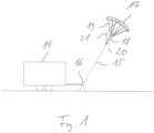
- An inventive kite system comprises a ground station 14 with a hauling point 16 from which a towing rope 15 extends to a kite 17.
- a gondola 18 is connected to the upper end of the towing rope 15 and is connected to the kite 17 via a line tree 19.
- a control system is arranged in the gondola 18 and is designed to change the length of the lines of the line tree 19 individually or in groups in order to steer the kite 17 along predetermined flight paths.
- the ground station 14 comprises a generator, to whose drive shaft the traction cable 15 is connected. If a pulling force is exerted on the traction cable 15 with the kite 17 and the traction cable 15 is released over the pull point 16 under the influence of the pulling force, the generator can be driven and electrical energy can be generated. The electrical energy can, for example, be fed into an electrical connection network.
- a predetermined breaking point 20 is formed between the gondola 18 and the hauling point 16.
- the predetermined breaking point 20 is arranged at a small distance from the gondola 18 and at a large distance from the hauling point 16, so that the traction cable 15 can be pulled in far can be done without the predetermined breaking point 20 running into the hole point 16.
- the traction rope 15 has a greater resistance to tensile forces than the predetermined breaking point 20. In the event of a tensile force overload, the predetermined breaking point 20 will break before the traction rope 15 or other components of the kite system are damaged.
- the predetermined breaking point 20 is bridged by a safety line 21, which forms a safety device in the sense of the invention.
- the safety line 21 ensures that the kite 17 cannot fly away unhindered even after the predetermined breaking point 20 has broken, but remains within the predetermined flight area.
- the lower end of the safety line 21 is attached to the towing rope 15 at a short distance from the predetermined breaking point 20.
- the upper end of the safety line 21 is attached to the kite 17.
- the kite 17 can initially move a little way away from the tow rope 15 before the suspension line 21 begins to exert a pulling force.
- the phase in which the predetermined breaking point 20 is broken but the suspension line 21 is not yet exerting a pulling force is referred to as the free-running phase.
- the suspension line 21 then begins to exert a pulling force on the kite 17 via a shock absorber, the functioning of which is explained in more detail below, in order to gently slow the kite 17 down. Once the shock absorber has been exhausted, the suspension line 21 is taut so that the kite 17 can no longer move any further away from the tow rope 15. In this state, the two ends of the suspension line 21 are at their maximum distance from each other, which is referred to as the final distance.
- the kite system is designed in such a way that when the final distance is reached, the kite 17 is sufficiently slowed down so that it can be retrieved without further damage.
- a predetermined breaking point 20 is shown, which is arranged between the upper end of the traction cable 15 and the gondola 18.
- the predetermined breaking point 20 comprises a shear bolt 22, which connects a first bolt holding element 23 and a second bolt holding element 24 to one another.
- the first bolt holding element 23 is connected to the gondola 18.
- the second bolt holding element 24 is connected to the upper end of the traction cable 15.
- the first bolt holding element 23 surrounds the second bolt holding element 24 from two sides, so that a hole formed in the first bolt holding element 23 is aligned with a hole in the second bolt holding element 24.
- the shear bolt 22 is inserted into the hole and has a weakening at the transition between the first bolt holding element 23 and the second bolt holding element 24. In the area of this weakening, the shear bolt 22 shears off when a defined tensile force is exceeded.
- the predetermined breaking point 20 is according to Fig.3 connected in one piece to the traction cable 15. In the area of the predetermined breaking point 20, the cross-section is reduced compared to the rest of the traction cable 15.
- the predetermined breaking point 20 is connected to the gondola 18 by a transition section 25.
- a sleeve 26 is arranged at the upper end of the traction cable 15 and extends around the traction cable 15. The lower end of the suspension line 21 is attached to the sleeve 26.
- the suspension line 21 extends along a curved path as long as the predetermined breaking point 20 is intact. Adjacent turns of the suspension line 21 are connected to one another by connecting pieces 27 which are shorter than the suspension line section to whose ends the connecting pieces are attached.
- the kite 17 pulls on the upper end of the suspension line 21.
- the suspension line 21 offers no resistance to this pull until all connecting pieces 27 are taut. If a predetermined pulling force is exceeded, which is less than the pulling force exerted by the kite 17, the connecting pieces 27 tear. As the kite 17 continues to move, the connecting pieces 27 are torn one after the other until finally the suspension line 21 is stretched to its maximum length, so that further movement of the kite 17 in the pulling direction is prevented.
- the connecting pieces 27 as a whole form a shock absorber, which slows down the movement of the kite 17 more and more.
- the kite system is designed so that the kite 17 is sufficiently slowed down when the suspension line 21 is fully tensioned. In this state, the kite 17 can be retrieved together with the gondola 18 without causing further damage.
Landscapes
- Engineering & Computer Science (AREA)
- Mechanical Engineering (AREA)
- Life Sciences & Earth Sciences (AREA)
- Sustainable Development (AREA)
- Sustainable Energy (AREA)
- Chemical & Material Sciences (AREA)
- Combustion & Propulsion (AREA)
- Ocean & Marine Engineering (AREA)
- Aviation & Aerospace Engineering (AREA)
- Catching Or Destruction (AREA)
- Wind Motors (AREA)
Description
- Die Erfindung betrifft ein Kitesystem mit einem Kite und einem Zugseil. Das Zugseil erstreckt sich zwischen dem Kite und einem Holepunkt am Boden.
- Bei einem solchen Kitesystem kann der Kite frei ausfliegen, wobei der Abstand zum Holepunkt durch die Länge des Zugseils definiert ist. Wenn das Zugseil reißt, kann der Kite seine Flugbahn verlassen und unter Umständen weit entfernt von dem zugedachten Flugraum auf dem Boden aufschlagen. Dies kann eine Gefährdung darstellen.
- Dokument
WO 2016/150561 A1 stellt ein Fluggerät für ein Windkraftwerk vor, wobei in einem Zugseil ein Punkt geringerer Widerstandskraft in der Nähe des Fluggeräts angeordnet sein kann, um eine Sollbruchstelle in dem Zugseil herzustellen. DokumentUS 2004/159747 A1 stellt eine Kite-Lenkstange mit einem ausfallsicheren Lösesystem vor. - Der Erfindung liegt die Aufgabe zugrunde, ein Kitesystem vorzustellen, bei dem das Risiko von durch den Kite verursachten Schäden vermindert ist. Ausgehend vom genannten Stand der Technik wird die Aufgabe gelöst mit den Merkmalen des Anspruchs 1. Vorteilhafte Ausführungsformen sind in den Unteransprüchen angegeben.
- Bei dem erfindungsgemäßen Kitesystem ist zwischen dem Kite und dem Zugseil eine Sollbruchstelle ausgebildet. Die Sollbruchstelle ist durch eine Fangeinrichtung überbrückt.
- Bevor das Zugseil reißt, kommt es zu einem Bruch an der Sollbruchstelle. Mit dem Bruch der Sollbruchstelle verändert sich der aerodynamische Zustand des Kites, was normalerweise mit einer Verminderung der auf das Zugseil einwirkenden Zugkraft einhergeht. Durch die Fangeinrichtung wird verhindert, dass der Kite sich unkontrolliert von dem Zugseil entfernen kann. Der Kite bleibt innerhalb des vorgesehenen Flugraums und kann zu Boden geholt werden, ohne dass es außerhalb des vorgesehenen Flugraums zu einer Gefährdung kommt.
- Der Kite kann durch einen Leinenbaum geführt sein. Als Leinenbaum wird eine Mehrzahl von Leinen bezeichnet, die an dem Kite angeschlagen sind und so zusammengeführt sind, dass sie die von dem Kite ausgeübte Zugkraft auf das obere Ende des Zugseils übertragen. Die Sollbruchstelle ist vorzugsweise zwischen dem unteren Ende des Leinenbaums und dem Zugseil angeordnet.
- Das untere Ende des Leinenbaums kann an einer Gondel befestigt sein, wobei in der Gondel eine Steuerung für den Kite angeordnet ist. Die Steuerung kann Stellelemente umfassen, mit denen die Länge einzelner Leinen zwischen der Gondel und dem Kite eingestellt werden kann. Durch eine Veränderung der Länge von einer oder mehreren Leinen kann die Bewegungsrichtung des Kites gesteuert werden. Die Steuerung kann so eingerichtet sein, dass der Kite entlang vorgegebener Flugbahnen gesteuert wird. Die Sollbruchstelle ist vorzugsweise zwischen der Gondel und dem Zugseil angeordnet.
- Die Sollbruchstelle umfasst ein Element, über das die gesamte von dem Kite ausgeübte Zugkraft geleitet wird. Die Standfestigkeit der Sollbruchstelle gegenüber Zugkräften ist geringer als die Standfestigkeit der übrigen zwischen dem Kite und dem Holepunkt am Boden angeordneten Elemente, die der gesamten Zugkraft des Kites ausgesetzt sind. Insbesondere hat die Sollbruchstelle eine geringere Standfestigkeit gegenüber Zugkräften als das Zugseil. Auf diese Weise kann sichergestellt werden, dass bei Auftreten einer Überlastsituation die Sollbruchstelle bricht, bevor ein anderes Element des Kitesystems die Grenze seiner Belastbarkeit erreicht. Die Überdimensionierung der anderen Elemente des Kitesystems gegenüber der Sollbruchstelle erfolgt unter Berücksichtigung einer angemessenen Sicherheitsreserve.
- Die Sollbruchstelle kann einen Scherbolzen umfassen, der bei Einwirkung einer vorgegebenen Zugkraft bricht. Der Scherbolzen kann mit der Richtung der Zugkraft einen rechten Winkel einschließen. Die Sollbruchstelle kann ein erstes Bolzen-Halteelement umfassen, das zwischen dem Scherbolzen und dem Zugseil angeordnet ist. Die Sollbruchstelle kann ein zweites Bolzen-Halteelement umfassen, das zwischen dem Scherbolzen und dem Kite angeordnet ist. Das erste und das zweite Bolzen-Halteelement können konzentrisch zueinander ausgerichtete Bohrungen umfassen. Insbesondere kann das erste Bolzen-Halteelement zwei Bohrungen aufweisen, die die Bohrung des zweiten Bolzen-Halteelements von zwei Seiten umgreifen. Der Scherbolzen kann in die Bohrungen des ersten und des zweiten Bolzen-Halteelements eingesetzt sein. Der Scherbolzen kann eine Schwächung aufweisen, die vorzugsweise am Übergang zwischen dem ersten Bolzen-Halteelement und dem zweiten Bolzen-Halteelement positioniert ist. Diese Schwächung kann den Bereich des Scherbolzens definieren, der bei Einwirken der Überlast abschert.
- In einer Ausführungsform der Erfindung ist die Sollbruchstelle einstückig mit dem Zugseil verbunden. Die Sollbruchstelle kann als schwächer dimensionierter Seilabschnitt ausgebildet sein, der in das obere Ende des Zugseils übergeht. Im Bereich zwischen der Sollbruchstelle und dem Holepunkt kann das Zugseil eine konstante Belastbarkeit gegenüber Zugkräften aufweisen. Die schwächer dimensionierte Sollbruchstelle kann mit einem Übergangsabschnitt an die Gondel des Kitesystems angeschlossen sein.
- Die Fangeinrichtung, die die Sollbruchstelle überbrückt, ist mit ihrem unteren Ende befestigt an einem zwischen der Sollbruchstelle und dem Holepunkt am Boden angeordneten Abschnitt des Kitesystems. Das obere Ende der Fangeinrichtung kann an einem auf der anderen Seite der Sollbruchstelle liegenden Abschnitt des Kitesystems befestigt sein. Das untere Ende der Fangeinrichtung ist vorzugsweise in einem geringen Abstand zu der Sollbruchstelle angeordnet. Der Abstand zwischen dem unteren Ende der Fangeinrichtung und der Sollbruchstelle ist vorzugsweise kleiner als 10 %, weiter vorzugsweise kleiner als 5 %, weiter vorzugsweise kleiner als 1 % der Länge des Zugseils. Das untere Ende der Fangeinrichtung kann an dem oberen Ende des Zugseils angeschlagen sein. Möglich ist auch, dass das untere Ende der Fangeinrichtung an einer mit dem Zugseil verbundenen Trageeinrichtung für die Sollbruchstelle angeschlagen ist.
- Das obere Ende der Fangeinrichtung kann an dem Kite angeschlagen sein. Es kann einen oder mehrere Anlenkpunkte zwischen dem oberen Ende der Fangeinrichtung und dem Kite geben. Der oder die Anlenkpunkte sind vorzugsweise so angeordnet, dass der Kite sich nach dem Brechen der Sollbruchstelle von alleine aus dem Wind dreht, so dass die auf das Zugseil wirkende Zugkraft abnimmt.
- Zusätzlich oder alternativ dazu kann das obere Ende der Fangeinrichtung an der Gondel angeschlagen sein. Ist das obere Ende der Fangeinrichtung sowohl an dem Kite als auch an der Gondel angeschlagen, so kann die Fangeinrichtung so bemessen sein, dass die Gondel relativ zu dem Kite schwenken kann, so dass der auf den Kite wirkende Winddruck vermindert wird. Insbesondere kann ein sich zu der Gondel erstreckender Abschnitt der Fangeinrichtung so bemessen sein, dass die Gondel sich nach dem Brechen der Sollbruchstelle über eine größere Strecke bewegen kann als der Kite.
- Zusätzlich oder alternativ dazu kann das obere Ende der Fangeinrichtung an einer oder mehreren Leinen des Leinenbaums angeschlagen sein. Durch geeignete Auswahl der Anlenkpunkte zwischen der Fangeinrichtung und den Leinen des Leinenbaums kann erreicht werden, dass der Kite nach dem Brechen der Sollbruchstelle einigermaßen kontrolliert seine Geschwindigkeit vermindert.
- Die Fangeinrichtung kann mit einem Ruckdämpfer ausgestattet sein, so dass die Fangeinrichtung nach dem Brechen der Sollbruchstelle nicht schlagartig blockiert, sondern dass die Fangeinrichtung bereits vor der vollständigen Blockade eine Zugkraft aufbaut. Die von der Fangeinrichtung vor dem Blockieren ausgeübte Zugkraft kann sich kontinuierlich erhöhen oder in mehreren Schritten ausgeübt werden. Der Ruckdämpfer kann beispielsweise ein Reibelement oder ein Federelement umfassen.
- Zusätzlich oder alternativ zu dem Ruckdämpfer kann die Fangeinrichtung einen Freilaufabschnitt aufweisen, so dass der Kite sich nach dem Brechen der Sollbruchstelle eine vorgegebene Strecke von dem Zugseil entfernen kann, bevor die Zugkraft der Fangeinrichtung eingreift. Nach dem Ende des Freilaufabschnitts kann die Fangeinrichtung beginnen, eine Zugkraft auszuüben. Mit dem Freilaufabschnitt kann der Umstand ausgenutzt werden, dass der Kite nach dem Brechen der Sollbruchstelle seinen aerodynamischen Zustand ändert und dadurch abgebremst wird. Das erste Abbremsen des Kites kann also erfolgen, ohne dass eine Zugkraft auf die Fangleine wirkt.
- Der Freilaufabschnitt kann so bemessen sein, dass er wenigstens so groß ist wie die elastische Dehnung des Zugseils. Elastische Dehnung des Zugseils bezeichnet die Strecke, um die sich das Zugseil verkürzt, wenn es nicht mehr unter der Zugkraft des Kites steht. Die elastische Dehnung bezieht sich auf den Zustand, in dem das Zugseil auf maximale Länge gefiert ist. Die elastische Dehnung kann beispielsweise zwischen 2 % und 5 % der Länge des Zugseils liegen. Wenn der Freilaufabschnitt größer ist als die elastische Dehnung des Zugseils, kann das Zugseil sich nach dem Brechen der Sollbruchstelle zusammenziehen, ohne dass die Fangeinrichtung gespannt ist.
- Solange die Sollbruchstelle intakt ist, haben das untere Ende der Fangeinrichtung und das am weitesten von dem unteren Ende entfernte obere Ende der Fangeinrichtung einen Anfangsabstand zueinander. Nach dem Brechen der Sollbruchstelle vergrößert sich der Abstand zwischen diesen beiden Punkten der Fangeinrichtung, bis die Fangleine blockiert und die beiden Punkte einen Endabstand zueinander haben. Die Bewegung der beiden Punkte der Fangeinrichtung relativ zueinander zwischen dem Anfangsabstand und dem Endabstand wird als Fangweg bezeichnet.
- Der Freilaufabschnitt kann sich über wenigstens 10 %, vorzugsweise wenigstens 20 %, weiter vorzugsweise wenigstens 50 % des Fangwegs erstrecken. Der verbleibende Teil des Fangwegs kann ganz oder teilweise von dem Ruckdämpfer aufgenommen werden.
- Die Fangeinrichtung kann eine die Sollbruchstelle überbrückende Fangleine umfassen. Die Fangleine kann entspannt sein, wenn die beiden Enden der Fangeinrichtung den Anfangsabstand zueinander haben. Die Fangleine kann gespannt sein, wenn die beiden Enden der Fangeinrichtung den Endabstand zueinander haben. Der Ruckdämpfer kann auf die Fangleine wirken, so dass eine vorgegebenen Zugkraft zu überwinden ist, um einen Abschnitt der Fangleine in einen gestreckten Zustand zu bringen. Beispielweise kann die Fangleine in sich vernäht sein, wobei die Naht so ausgebildet ist, dass sie nach Überwindung eines vorgegebenen Reißwiderstands reißt.
- Das Zugseil kann die einzige Verbindung zwischen der Sollbruchstelle und dem Holepunkt sein, die zur Aufnahme von Zugkräften geeignet ist. Als Holepunkt wird der Befestigungspunkt am Boden bezeichnet, auf den das Zugseil zuläuft. Das erfindungsgemäße Kitesystem kann so ausgelegt sein, dass der Holepunkt auch genutzt wird, um das Zugseil einzuholen. Einholen bedeutet, das Zugseil zwischen dem Holepunkt und dem Kite zu verkürzen, so dass der Kite herangeholt wird.
- Das Kitesystem kann eine Energieerzeugungskomponente umfassen, die durch Fieren und Einholen des Zugseils eingebrachte Energie in eine andere Energieform umwandelt. Die in der Energieerzeugungskomponente kann beispielsweise ein Generator sein, mit dem elektrische Energie erzeugt wird. Wenn das Kitesystem auf diese Weise verwendet wird, gibt es regelmäßig einen Abschnitt des Zugseils, der im Bereich des Holepunkts umgelenkt und/oder aufgewickelt wird. Dieser Abschnitt des Zugseils wird in verstärktem Maße belastet. Die Sollbruchstelle und/oder der untere Anlenkpunkt der Fangeinrichtung liegen vorzugsweise außerhalb dieses Abschnitts des Zugseils.
- Die Erfindung wird nachfolgend unter Bezugnahme auf die beigefügten Zeichnungen anhand vorteilhafter Ausführungsformen beispielhaft beschrieben. Es zeigen:
- Fig. 1:
- eine schematische Darstellung eines erfindungsgemäßen Kitesystems;
- Fig. 2:
- eine Sollbruchstelle bei einer ersten Ausführungsform der Erfindung;
- Fig. 3:
- eine Sollbruchstelle bei einer zweiten Ausführungsform der Erfindung;
- Fig. 4:
- eine Fangleine eines erfindungsgemäßen Kitesystems.
- Ein erfindungsgemäßes Kitesystem gemäß
Fig. 1 umfasst eine Bodenstation 14 mit einem Holepunkt 16, von dem sich ein Zugseil 15 zu einem Kite 17 erstreckt. An das obere Ende des Zugseils 15 ist eine Gondel 18 angeschlossen, die über einen Leinenbaum 19 mit dem Kite 17 verbunden ist. In der Gondel 18 ist eine Steuerung angeordnet, die dazu ausgelegt ist, die Länge der Leinen des Leinenbaums 19 einzeln oder in Gruppen zu verändern, um den Kite 17 entlang vorgegebener Flugbahnen zu lenken. - Die Bodenstation 14 umfasst einen Generator, an dessen Antriebswelle das Zugseil 15 angeschlossen ist. Wird mit dem Kite 17 eine Zugkraft auf das Zugseil 15 ausgeübt und das Zugseil 15 unter dem Einfluss der Zugkraft über den Holepunkt 16 gefiert, so kann der Generator angetrieben werden und elektrische Energie erzeugt werden. Die elektrische Energie kann beispielsweise in ein elektrisches Anschlussnetz eingespeist werden.
- Zwischen der Gondel 18 und dem Holepunkt 16 ist eine Sollbruchstelle 20 ausgebildet. Die Sollbruchstelle 20 ist mit geringem Abstand zu der Gondel 18 und mit großem Abstand zu dem Holepunkt 16 angeordnet, so dass das Zugseil 15 weit eingeholt werden kann, ohne dass die Sollbruchstelle 20 in den Holepunkt 16 läuft.
- Das Zugseil 15 hat eine größere Beständigkeit gegenüber Zugkräften als die Sollbruchstelle 20. Im Fall einer Zugkraft-Überlastung kommt es zu einem Bruch der Sollbruchstelle 20, bevor das Zugseil 15 oder andere Komponenten des Kitesystems Schaden nehmen.
- Die Sollbruchstelle 20 ist mit einer Fangleine 21 überbrückt, die eine Fangeinrichtung im Sinne der Erfindung bildet. Durch die Fangleine 21 wird bewirkt, dass der Kite 17 auch nach einem Bruch der Sollbruchstelle 20 nicht ungehindert davon fliegen kann, sondern innerhalb des vorbestimmten Flugbereichs bleibt. Das untere Ende der Fangleine 21 ist mit geringem Abstand zu der Sollbruchstelle 20 an dem Zugseil 15 angeschlagen. Das obere Ende der Fangleine 21 ist an dem Kite 17 angeschlagen.
- Kommt es zu einem Bruch der Sollbruchstelle 20, so kann der Kite 17 sich zunächst ein Stück weit von dem Zugseil 15 entfernen, bevor die Fangleine 21 beginnt, eine Zugkraft auszuüben. Die Phase, in der die Sollbruchstelle 20 gebrochen ist, die Fangleine 21 aber noch keine Zugkraft ausübt, wird als Freilaufphase bezeichnet. Anschließend beginnt die Fangleine 21, über einen Ruckdämpfer, dessen Funktionsweise unten näher erläutert wird, eine Zugkraft auf den Kite 17 auszuüben, um den Kite 17 sanft abzubremsen. Nach Erschöpfung des Ruckdämpfers ist die Fangleine 21 gespannt, so dass der Kite 17 sich nicht mehr weiter von dem Zugseil 15 entfernen kann. In diesem Zustand haben die beiden Enden der Fangleine 21 ihren maximalen Abstand zueinander, der als Endabstand bezeichnet wird.
- Das Kitesystem ist so ausgelegt, dass der Kite 17 bei Erreichen des Endabstands hinreichend abgebremst ist, so dass er ohne weitere Schäden eingeholt werden kann.
- In
Fig. 2 ist ein Ausführungsbeispiel einer Sollbruchstelle 20 gezeigt, die zwischen dem oberen Ende des Zugseils 15 und der Gondel 18 angeordnet ist. Die Sollbruchstelle 20 umfasst einen Scherbolzen 22, der ein erstes Bolzen-Halteelement 23 und ein zweites Bolzen-Halteelement 24 miteinander verbindet. Das erste Bolzen-Halteelement 23 ist an die Gondel 18 angeschlossen. Das zweite Bolzen-Halteelement 24 schließt an das obere Ende des Zugseils 15 an. Das erste Bolzen-Halteelement 23 umgreift das zweite Bolzen-Halteelement 24 von zwei Seiten, so dass eine in dem ersten Bolzen-Halteelement 23 ausgebildete Bohrung mit einer Bohrung in dem zweiten Bolzen-Halteelement 24 fluchtet. Der Scherbolzen 22 ist in die Bohrung eingeführt und hat am Übergang zwischen dem ersten Bolzen-Halteelement 23 und dem zweiten Bolzen-Halteelement 24 eine Schwächung. Im Bereich dieser Schwächung schert der Scherbolzen 22 bei Überschreiten einer definierten Zugkraft ab. - In einer alternativen Ausführungsform der Erfindung ist die Sollbruchstelle 20 gemäß
Fig. 3 einstückig mit dem Zugseil 15 verbunden. Im Bereich der Sollbruchstelle 20 ist der Querschnitt verglichen mit dem Rest des Zugseils 15 vermindert. Mit einem Übergangsabschnitt 25 ist die Sollbruchstelle 20 an die Gondel 18 angeschlossen. Am oberen Ende des Zugseils 15 ist eine Manschette 26 angeordnet, die sich um das Zugseil 15 herum erstreckt. An der Manschette 26 ist das untere Ende der Fangleine 21 befestigt. - Gemäß
Fig. 4 erstreckt die Fangleine 21 sich entlang einem geschwungenen Weg, solange die Sollbruchstelle 20 intakt ist. Benachbarte Windungen der Fangleine 21 sind durch Verbindungsstücke 27 miteinander verbunden, die kürzer sind als der Fangleinenabschnitt, an dessen Enden die Verbindungsstücke befestigt sind. - Kommt es zu einem Bruch der Sollbruchstelle 20, so zieht der Kite 17 an dem oberen Ende der Fangleine 21. Die Fangleine 21 setzt diesem Zug so lange keinen Widerstand entgegen, bis alle Verbindungsstücke 27 gespannt sind. Bei Überschreiten einer vorgegebenen Zugkraft, die kleiner ist als die von dem Kite 17 ausgeübte Zugkraft, reißen die Verbindungsstücke 27. Mit der weiteren Bewegung des Kites 17 werden die Verbindungsstücke 27 nacheinander zerrissen, bis schließlich die Fangleine 21 auf ihre maximale Länge gedehnt ist, so dass eine weitere Bewegung des Kites 17 in Zugrichtung verhindert wird. Die Verbindungsstücke 27 bilden in ihrer Gesamtheit einen Ruckdämpfer, durch den die Bewegung des Kites 17 immer weiter abgebremst wird.
- Das Kitesystem ist so eingerichtet, dass der Kite 17 hinreichend abgebremst ist, wenn die Fangleine 21 voll gespannt ist. In diesem Zustand kann der Kite 17 zusammen mit der Gondel 18 eingeholt werden, ohne dass es zu weiteren Schäden kommt.
Claims (13)
- Kitesystem mit einem Kite (17) und mit einem Zugseil (15), wobei das Zugseil (15) sich zwischen dem Kite (17) und einem Holepunkt (16) am Boden erstreckt, wobei zwischen dem Kite (17) und dem Zugseil (15) eine Sollbruchstelle (20) ausgebildet ist, dadurch gekennzeichnet, dass die Sollbruchstelle (20) durch eine Fangeinrichtung (21) überbrückt ist.
- Kitesystem nach Anspruch 1, dadurch gekennzeichnet, dass die Sollbruchstelle (20) zwischen einem Leinenbaum (19) des Kites (17) und dem Zugseil (15) angeordnet ist.
- Kitesystem nach Anspruch 1 oder 2, dadurch gekennzeichnet, dass die Sollbruchstelle (20) zwischen einer Gondel (18) des Kitesystems und dem Zugseil (15) angeordnet ist.
- Kitesystem nach einem der Ansprüche 1 bis 3, dadurch gekennzeichnet, dass die Sollbruchstelle (20) einen Scherbolzen (22) umfasst.
- Kitesystem nach Anspruch 4, dadurch gekennzeichnet, dass der Scherbolzen (22) eine Schwächung aufweist, die an einem Übergang zwischen einem ersten Bolzen-Halteelement (23) und einem zweiten Bolzen-Halteelement (24) angeordnet ist.
- Kitesystem nach einem der Ansprüche 1 bis 3, dadurch gekennzeichnet, dass die Sollbruchstellen (20) einstückig mit dem Zugseil (15) verbunden ist.
- Kitesystem nach einem der Ansprüche 1 bis 6, dadurch gekennzeichnet, dass der Abstand zwischen dem unteren Ende der Fangeinrichtung (21) und der Sollbruchstelle (20) kleiner ist als 10 %, vorzugsweise kleiner ist als 5 %, weiter vorzugsweise kleiner ist als 1 % der Länge des Zugseils (15).
- Kitesystem nach einem der Ansprüche 1 bis 7, dadurch gekennzeichnet, dass das obere Ende der Fangeinrichtung (21) an dem Kite (17), an dem Leinenbaum (19) und/oder an der Gondel (18) angeschlagen ist.
- Kitesystem nach einem der Ansprüche 1 bis 8, dadurch gekennzeichnet, dass die Fangeinrichtung (21) mit einem Ruckdämpfer (27) ausgestattet ist.
- Kitesystem nach einem der Ansprüche 1 bis 9, dadurch gekennzeichnet, dass die Fangeinrichtung (21) einen Freilaufabschnitt aufweist, so dass der Kite (17) sich nach dem Brechen der Sollbruchstelle (20) eine vorgegebene Strecke von dem Zugseil (15) entfernen kann, bevor eine Zugkraft der Fangeinrichtung (21) eingreift.
- Kitesystem nach einem der Ansprüche 1 bis 10, dadurch gekennzeichnet, dass der Freilaufabschnitt kann sich über wenigstens 10 %, vorzugsweise wenigstens 20 %, weiter vorzugsweise wenigstens 50 % des Fangwegs erstreckt.
- Kitesystem nach einem der Ansprüche 1 bis 11, dadurch gekennzeichnet, dass die Fangeinrichtung (21) eine die Sollbruchstelle (20) überbrückende Fangleine umfasst.
- Kitesystem nach Anspruch 12, soweit zurückgezogen auf Anspruch 9, dadurch gekennzeichnet, dass der Ruckdämpfer (27) auf die Fangleine (21) wirkt, so dass eine vorgegebenen Zugkraft zu überwinden ist, um einen Abschnitt der Fangleine (21) in einen gestreckten Zustand zu bringen.
Priority Applications (1)
| Application Number | Priority Date | Filing Date | Title |
|---|---|---|---|
| EP17191448.4A EP3456630B1 (de) | 2017-09-15 | 2017-09-15 | Kitesystem |
Applications Claiming Priority (1)
| Application Number | Priority Date | Filing Date | Title |
|---|---|---|---|
| EP17191448.4A EP3456630B1 (de) | 2017-09-15 | 2017-09-15 | Kitesystem |
Publications (3)
| Publication Number | Publication Date |
|---|---|
| EP3456630A1 EP3456630A1 (de) | 2019-03-20 |
| EP3456630C0 EP3456630C0 (de) | 2024-08-14 |
| EP3456630B1 true EP3456630B1 (de) | 2024-08-14 |
Family
ID=59914307
Family Applications (1)
| Application Number | Title | Priority Date | Filing Date |
|---|---|---|---|
| EP17191448.4A Active EP3456630B1 (de) | 2017-09-15 | 2017-09-15 | Kitesystem |
Country Status (1)
| Country | Link |
|---|---|
| EP (1) | EP3456630B1 (de) |
Families Citing this family (1)
| Publication number | Priority date | Publication date | Assignee | Title |
|---|---|---|---|---|
| EP4234401A1 (de) | 2022-02-28 | 2023-08-30 | SkySails Power GmbH | Verfahren zum landen eines kitesystems und kitesystem |
Family Cites Families (3)
| Publication number | Priority date | Publication date | Assignee | Title |
|---|---|---|---|---|
| US6830220B2 (en) * | 2003-02-19 | 2004-12-14 | Max Robert Runyan | Kite control bar with ninety-degree handles and fail-safe release system |
| DE202011104335U1 (de) * | 2011-08-12 | 2011-09-29 | Stefan Radev | Kite Sicherheitsleine |
| US10953970B2 (en) * | 2015-03-20 | 2021-03-23 | Skypull Sa | Traction air device, air device for a wind plant and wind plant for electric power production, ship provided with a traction air device |
-
2017
- 2017-09-15 EP EP17191448.4A patent/EP3456630B1/de active Active
Also Published As
| Publication number | Publication date |
|---|---|
| EP3456630A1 (de) | 2019-03-20 |
| EP3456630C0 (de) | 2024-08-14 |
Similar Documents
| Publication | Publication Date | Title |
|---|---|---|
| DE102005035437B3 (de) | Fluggerät mit einem Rettungslandesystem | |
| EP2920369B1 (de) | Aufreissbremse | |
| EP3948150B1 (de) | Abfangnetz mit absorptionseinrichtung zum abfangen von drohnen | |
| WO2010031377A2 (de) | Flugkörper mit zumindest einem bremsfallschirm sowie befestigungsvorrichtung zur befestigung eines bremsfallschirms an einem flugkörper | |
| DE102011003602B4 (de) | Sicherungssystem für ein Rotorblatt einer Windenergieanlage, Rotorblatt und Windenergieanlage | |
| EP3938648B1 (de) | Flanschverbindung, windenergieanlage mit selbiger, und verfahren zur überwachung selbiger | |
| DE2834435A1 (de) | Trennvorrichtung zum loesen einer aerodynamischen bremseinrichtung von einer last | |
| EP1939132A2 (de) | Fernbetätigbarer Lastbügel oder -haken | |
| EP3456630A1 (de) | Kitesystem | |
| DE20303089U1 (de) | Sportgerät mit einer Sicherheitseinrichtung | |
| EP1569726B1 (de) | Sportgerät mit einer sicherheitseinrichtung | |
| DE2503936B2 (de) | LastentrennschloB für Fallschirme | |
| EP4234401A1 (de) | Verfahren zum landen eines kitesystems und kitesystem | |
| DE10304072A1 (de) | Sportgerät mit zwei Lenkleinen und einer Sicherheitseinrichtung | |
| AT525117B1 (de) | Vorrichtung zum Lösen einer mit einer Zugkraft belasteten Seilverbindung | |
| DE10258637B4 (de) | Sportgerät mit einer Sicherheitseinrichtung | |
| EP2643257B1 (de) | Seilfangvorrichtung | |
| EP2198696A1 (de) | Zugsystem | |
| DE4415899C2 (de) | Schleppleitungsvorrichtung | |
| EP4234390A1 (de) | Kitesystem | |
| DE19800666C2 (de) | Seilfangvorrichtung | |
| DE4244366A1 (de) | Verfahren zum Verlegen eines zwischen weit auseinanderliegenden Auflagern wie Freileitungs- oder Seilbahnmasten laufenden Seils, Kabels o. dgl. | |
| DE102022130489A1 (de) | Arbeitsbühne | |
| DE202025101592U1 (de) | Vorrichtung zum Unterstützen des Öffnungsvorgangs eines Rettungsschirmes für ein Luftfahrzeug | |
| DE102009053342A1 (de) | Einrichtung zum Unterbrechen einer Zugkraft in einem Zugsystem |
Legal Events
| Date | Code | Title | Description |
|---|---|---|---|
| PUAI | Public reference made under article 153(3) epc to a published international application that has entered the european phase |
Free format text: ORIGINAL CODE: 0009012 |
|
| STAA | Information on the status of an ep patent application or granted ep patent |
Free format text: STATUS: THE APPLICATION HAS BEEN PUBLISHED |
|
| AK | Designated contracting states |
Kind code of ref document: A1 Designated state(s): AL AT BE BG CH CY CZ DE DK EE ES FI FR GB GR HR HU IE IS IT LI LT LU LV MC MK MT NL NO PL PT RO RS SE SI SK SM TR |
|
| AX | Request for extension of the european patent |
Extension state: BA ME |
|
| STAA | Information on the status of an ep patent application or granted ep patent |
Free format text: STATUS: REQUEST FOR EXAMINATION WAS MADE |
|
| 17P | Request for examination filed |
Effective date: 20190913 |
|
| RBV | Designated contracting states (corrected) |
Designated state(s): AL AT BE BG CH CY CZ DE DK EE ES FI FR GB GR HR HU IE IS IT LI LT LU LV MC MK MT NL NO PL PT RO RS SE SI SK SM TR |
|
| STAA | Information on the status of an ep patent application or granted ep patent |
Free format text: STATUS: EXAMINATION IS IN PROGRESS |
|
| 17Q | First examination report despatched |
Effective date: 20220426 |
|
| P01 | Opt-out of the competence of the unified patent court (upc) registered |
Effective date: 20230525 |
|
| GRAP | Despatch of communication of intention to grant a patent |
Free format text: ORIGINAL CODE: EPIDOSNIGR1 |
|
| STAA | Information on the status of an ep patent application or granted ep patent |
Free format text: STATUS: GRANT OF PATENT IS INTENDED |
|
| RIC1 | Information provided on ipc code assigned before grant |
Ipc: B64F 1/14 20060101ALI20240326BHEP Ipc: B63H 9/06 20060101ALI20240326BHEP Ipc: B64C 31/06 20060101AFI20240326BHEP |
|
| INTG | Intention to grant announced |
Effective date: 20240423 |
|
| GRAS | Grant fee paid |
Free format text: ORIGINAL CODE: EPIDOSNIGR3 |
|
| GRAA | (expected) grant |
Free format text: ORIGINAL CODE: 0009210 |
|
| STAA | Information on the status of an ep patent application or granted ep patent |
Free format text: STATUS: THE PATENT HAS BEEN GRANTED |
|
| AK | Designated contracting states |
Kind code of ref document: B1 Designated state(s): AL AT BE BG CH CY CZ DE DK EE ES FI FR GB GR HR HU IE IS IT LI LT LU LV MC MK MT NL NO PL PT RO RS SE SI SK SM TR |
|
| REG | Reference to a national code |
Ref country code: GB Ref legal event code: FG4D Free format text: NOT ENGLISH |
|
| REG | Reference to a national code |
Ref country code: CH Ref legal event code: EP |
|
| REG | Reference to a national code |
Ref country code: DE Ref legal event code: R096 Ref document number: 502017016341 Country of ref document: DE |
|
| REG | Reference to a national code |
Ref country code: IE Ref legal event code: FG4D Free format text: LANGUAGE OF EP DOCUMENT: GERMAN |
|
| U01 | Request for unitary effect filed |
Effective date: 20240905 |
|
| RAP4 | Party data changed (patent owner data changed or rights of a patent transferred) |
Owner name: SKYSAILS POWER GMBH |
|
| U07 | Unitary effect registered |
Designated state(s): AT BE BG DE DK EE FI FR IT LT LU LV MT NL PT RO SE SI Effective date: 20241004 |
|
| U20 | Renewal fee for the european patent with unitary effect paid |
Year of fee payment: 8 Effective date: 20240930 |
|
| P04 | Withdrawal of opt-out of the competence of the unified patent court (upc) registered |
Free format text: CASE NUMBER: APP_54061/2024 Effective date: 20240930 |
|
| P05 | Withdrawal of opt-out of the competence of the unified patent court (upc) changed |
Free format text: CASE NUMBER: APP_54061/2024 Effective date: 20241004 |
|
| PG25 | Lapsed in a contracting state [announced via postgrant information from national office to epo] |
Ref country code: NO Free format text: LAPSE BECAUSE OF FAILURE TO SUBMIT A TRANSLATION OF THE DESCRIPTION OR TO PAY THE FEE WITHIN THE PRESCRIBED TIME-LIMIT Effective date: 20241114 |
|
| PG25 | Lapsed in a contracting state [announced via postgrant information from national office to epo] |
Ref country code: PL Free format text: LAPSE BECAUSE OF FAILURE TO SUBMIT A TRANSLATION OF THE DESCRIPTION OR TO PAY THE FEE WITHIN THE PRESCRIBED TIME-LIMIT Effective date: 20240814 Ref country code: GR Free format text: LAPSE BECAUSE OF FAILURE TO SUBMIT A TRANSLATION OF THE DESCRIPTION OR TO PAY THE FEE WITHIN THE PRESCRIBED TIME-LIMIT Effective date: 20241115 |
|
| PG25 | Lapsed in a contracting state [announced via postgrant information from national office to epo] |
Ref country code: IS Free format text: LAPSE BECAUSE OF FAILURE TO SUBMIT A TRANSLATION OF THE DESCRIPTION OR TO PAY THE FEE WITHIN THE PRESCRIBED TIME-LIMIT Effective date: 20241214 |
|
| PG25 | Lapsed in a contracting state [announced via postgrant information from national office to epo] |
Ref country code: HR Free format text: LAPSE BECAUSE OF FAILURE TO SUBMIT A TRANSLATION OF THE DESCRIPTION OR TO PAY THE FEE WITHIN THE PRESCRIBED TIME-LIMIT Effective date: 20240814 |
|
| PG25 | Lapsed in a contracting state [announced via postgrant information from national office to epo] |
Ref country code: ES Free format text: LAPSE BECAUSE OF FAILURE TO SUBMIT A TRANSLATION OF THE DESCRIPTION OR TO PAY THE FEE WITHIN THE PRESCRIBED TIME-LIMIT Effective date: 20240814 Ref country code: RS Free format text: LAPSE BECAUSE OF FAILURE TO SUBMIT A TRANSLATION OF THE DESCRIPTION OR TO PAY THE FEE WITHIN THE PRESCRIBED TIME-LIMIT Effective date: 20241114 |
|
| PG25 | Lapsed in a contracting state [announced via postgrant information from national office to epo] |
Ref country code: RS Free format text: LAPSE BECAUSE OF FAILURE TO SUBMIT A TRANSLATION OF THE DESCRIPTION OR TO PAY THE FEE WITHIN THE PRESCRIBED TIME-LIMIT Effective date: 20241114 Ref country code: PL Free format text: LAPSE BECAUSE OF FAILURE TO SUBMIT A TRANSLATION OF THE DESCRIPTION OR TO PAY THE FEE WITHIN THE PRESCRIBED TIME-LIMIT Effective date: 20240814 Ref country code: NO Free format text: LAPSE BECAUSE OF FAILURE TO SUBMIT A TRANSLATION OF THE DESCRIPTION OR TO PAY THE FEE WITHIN THE PRESCRIBED TIME-LIMIT Effective date: 20241114 Ref country code: IS Free format text: LAPSE BECAUSE OF FAILURE TO SUBMIT A TRANSLATION OF THE DESCRIPTION OR TO PAY THE FEE WITHIN THE PRESCRIBED TIME-LIMIT Effective date: 20241214 Ref country code: HR Free format text: LAPSE BECAUSE OF FAILURE TO SUBMIT A TRANSLATION OF THE DESCRIPTION OR TO PAY THE FEE WITHIN THE PRESCRIBED TIME-LIMIT Effective date: 20240814 Ref country code: GR Free format text: LAPSE BECAUSE OF FAILURE TO SUBMIT A TRANSLATION OF THE DESCRIPTION OR TO PAY THE FEE WITHIN THE PRESCRIBED TIME-LIMIT Effective date: 20241115 Ref country code: ES Free format text: LAPSE BECAUSE OF FAILURE TO SUBMIT A TRANSLATION OF THE DESCRIPTION OR TO PAY THE FEE WITHIN THE PRESCRIBED TIME-LIMIT Effective date: 20240814 |
|
| PG25 | Lapsed in a contracting state [announced via postgrant information from national office to epo] |
Ref country code: SM Free format text: LAPSE BECAUSE OF FAILURE TO SUBMIT A TRANSLATION OF THE DESCRIPTION OR TO PAY THE FEE WITHIN THE PRESCRIBED TIME-LIMIT Effective date: 20240814 |
|
| PG25 | Lapsed in a contracting state [announced via postgrant information from national office to epo] |
Ref country code: CZ Free format text: LAPSE BECAUSE OF FAILURE TO SUBMIT A TRANSLATION OF THE DESCRIPTION OR TO PAY THE FEE WITHIN THE PRESCRIBED TIME-LIMIT Effective date: 20240814 |
|
| PG25 | Lapsed in a contracting state [announced via postgrant information from national office to epo] |
Ref country code: SK Free format text: LAPSE BECAUSE OF FAILURE TO SUBMIT A TRANSLATION OF THE DESCRIPTION OR TO PAY THE FEE WITHIN THE PRESCRIBED TIME-LIMIT Effective date: 20240814 |
|
| REG | Reference to a national code |
Ref country code: CH Ref legal event code: PL |
|
| PLBE | No opposition filed within time limit |
Free format text: ORIGINAL CODE: 0009261 |
|
| STAA | Information on the status of an ep patent application or granted ep patent |
Free format text: STATUS: NO OPPOSITION FILED WITHIN TIME LIMIT |
|
| PG25 | Lapsed in a contracting state [announced via postgrant information from national office to epo] |
Ref country code: MC Free format text: LAPSE BECAUSE OF FAILURE TO SUBMIT A TRANSLATION OF THE DESCRIPTION OR TO PAY THE FEE WITHIN THE PRESCRIBED TIME-LIMIT Effective date: 20240814 |
|
| 26N | No opposition filed |
Effective date: 20250515 |
|
| GBPC | Gb: european patent ceased through non-payment of renewal fee |
Effective date: 20241114 |
|
| PG25 | Lapsed in a contracting state [announced via postgrant information from national office to epo] |
Ref country code: CH Free format text: LAPSE BECAUSE OF NON-PAYMENT OF DUE FEES Effective date: 20240930 |
|
| PG25 | Lapsed in a contracting state [announced via postgrant information from national office to epo] |
Ref country code: IE Free format text: LAPSE BECAUSE OF NON-PAYMENT OF DUE FEES Effective date: 20240915 |
|
| PG25 | Lapsed in a contracting state [announced via postgrant information from national office to epo] |
Ref country code: GB Free format text: LAPSE BECAUSE OF NON-PAYMENT OF DUE FEES Effective date: 20241114 |
|
| U20 | Renewal fee for the european patent with unitary effect paid |
Year of fee payment: 9 Effective date: 20250924 |
|
| PG25 | Lapsed in a contracting state [announced via postgrant information from national office to epo] |
Ref country code: CY Free format text: LAPSE BECAUSE OF FAILURE TO SUBMIT A TRANSLATION OF THE DESCRIPTION OR TO PAY THE FEE WITHIN THE PRESCRIBED TIME-LIMIT; INVALID AB INITIO Effective date: 20170915 |
|
| PG25 | Lapsed in a contracting state [announced via postgrant information from national office to epo] |
Ref country code: HU Free format text: LAPSE BECAUSE OF FAILURE TO SUBMIT A TRANSLATION OF THE DESCRIPTION OR TO PAY THE FEE WITHIN THE PRESCRIBED TIME-LIMIT; INVALID AB INITIO Effective date: 20170915 |