EP3456162B1 - Gehäuse mit talkgefülltem pp und integriertem aluminiumkühlkörper mit elastomerschichten für elektronisches modul - Google Patents
Gehäuse mit talkgefülltem pp und integriertem aluminiumkühlkörper mit elastomerschichten für elektronisches modul Download PDFInfo
- Publication number
- EP3456162B1 EP3456162B1 EP16901569.0A EP16901569A EP3456162B1 EP 3456162 B1 EP3456162 B1 EP 3456162B1 EP 16901569 A EP16901569 A EP 16901569A EP 3456162 B1 EP3456162 B1 EP 3456162B1
- Authority
- EP
- European Patent Office
- Prior art keywords
- heat sink
- plastic housing
- plastic
- housing portion
- housing
- Prior art date
- Legal status (The legal status is an assumption and is not a legal conclusion. Google has not performed a legal analysis and makes no representation as to the accuracy of the status listed.)
- Active
Links
Images


Classifications
-
- H—ELECTRICITY
- H05—ELECTRIC TECHNIQUES NOT OTHERWISE PROVIDED FOR
- H05K—PRINTED CIRCUITS; CASINGS OR CONSTRUCTIONAL DETAILS OF ELECTRIC APPARATUS; MANUFACTURE OF ASSEMBLAGES OF ELECTRICAL COMPONENTS
- H05K7/00—Constructional details common to different types of electric apparatus
- H05K7/20—Modifications to facilitate cooling, ventilating, or heating
- H05K7/2039—Modifications to facilitate cooling, ventilating, or heating characterised by the heat transfer by conduction from the heat generating element to a dissipating body
- H05K7/20409—Outer radiating structures on heat dissipating housings, e.g. fins integrated with the housing
- H05K7/20418—Outer radiating structures on heat dissipating housings, e.g. fins integrated with the housing the radiating structures being additional and fastened onto the housing
Definitions
- the present application relates to an improved plastic housing with a heat sink for an electronic device.
- the plastic housing includes polypropylene (PP), which is filled with talc.
- thermal management methods A wide range of thermal management methods is available for electronic devices. These thermal management methods can be categorized into two groups, namely active heat dissipation methods and passive heat dissipation methods.
- the active heat dissipation methods use an energized mechanical device to remove heat.
- the mechanical device include a device for forcing air, a device for forcing liquid, and a solid-state heat pump.
- the passive heat dissipation methods use a component to remove heat. Examples of the component include a heat sink, a heat spreader, and a thermal interface material. These heat dissipation methods often use a few parts or components to form a complete thermal management system.
- WO 2007/122239 A1 describes a preparation of a polypropylene having a Melt Flow Rate (MFR) of 230 degree C, 2.16 kg from 45 to 150 grams/10 minutes. This polypropylene is suitable for preparing a living hinge.
- MFR Melt Flow Rate
- WO 2014/036096 A1 describes a housing unit with a heat sink inserted into an opening in the cover.
- the heat sink has a lip which forms a seal between the heat sink and the cover.
- US 5 212 627 A describes an overmoulded heat sink forming part of a housing for a connector.
- the living hinge frequently also referred to as a plastic hinge, provides an integrated and flexible connection between two pieces of a moulded polymer part, which allows the two pieces to bend along a line of the hinge.
- PP polypropylene
- the application provides an improved housing unit for surrounding and protecting an electronic device of a vehicle.
- the vehicle is used for transporting goods and people.
- the electronic device includes active components, such as microchips and transistors, which uses electricity and generates heat. In a general sense, the electronic device be used for other application, instead of the vehicle.
- the housing unit includes a heat sink and a plastic housing.
- the plastic housing includes a polypropylene (PP) material, which is filled with talc.
- PP polypropylene
- the talc filled PP material allows the plastic housing to be rigid while having a low cost.
- the talc filled PP material has often has a low elongation or expansion. In other words, the plastic housing has low flexibility.
- the plastic housing is integrated with the heat sink or is formed around the heat sink such that the plastic housing is connected with the heat sink.
- the heat sink receives heat from the energized electronic device.
- the heat sink then dissipates this heat.
- the temperature of the heat sink also rises, wherein the heat sink then expands often slightly.
- the housing unit includes one or more elastomer layers.
- the elastomer layer is placed next to an area of the heat sink such that the elastomer layer is placed between a part of the heat sink and a part of the plastic housing.
- the elastomer layer is also in contact with the heat sink part and in contact with the plastic housing part.
- the arrangement of the elastomer layers prevents the plastic housing from receiving an expansion force of the heated heat sink.
- the elastomer layers absorb the expansion of the heated heat sink such that the plastic housing does not receive any or little force from the enlarged heat sink.
- This arrangement of the housing unit advantageously provides the housing unit with a low cost due to its talc-filled PP material while using the elastomer layer to accommodate the low flexibility of the talc-filled PP material.
- the housing unit can have several additional features.
- the heat sink often includes a contact area for touching the electronic device in order to receive heat by conduction.
- the plastic housing also often includes a first plastic housing portion with a second plastic housing as well as a plastic hinge being integrally connected to the first plastic housing portion and to second plastic housing. These parts can be produced in a single step using injection moulding to save cost.
- the first plastic housing portion and the second plastic housing portion can include a plastic locking mechanism for locking the first plastic housing portion to the second plastic housing portion.
- the locking mechanism can attach the first plastic housing portion to the second plastic housing portion after an electronic device is inserted into the plastic housing.
- the first plastic housing portion can include an opening for receiving easily the heat sink.
- a rim of the opening can also include at least one groove part for receiving and gripping the heat sink.
- the second plastic housing portion can also include a service door or cover as well as a plastic hinge for connecting the service door to a part of the second plastic housing portion.
- the second plastic housing portion with the service door and the plastic hinge can be produced in one step using injection moulding to save cost.
- the door allows easy insertion of a component, such as a battery, into the housing unit.
- the service door and a part of the second plastic housing portion can include a plastic locking mechanism for locking the service door to the part of the second plastic housing portion.
- the plastic housing is often formed using insert moulding.
- the heat sink is inserted into a mould.
- a moulding material is injected into the mould, often at a high temperature, for forming the plastic housing.
- the elastomer layer is often provided on the heat sink using over-moulding.
- the over-moulding is a form of insert moulding.
- the heat sink is placed in a mould, wherein a part of the mould allows a elastomer material to be placed on one or more parts of the heat sink to form the elastomer layers.
- the heatsink is often formed from a metal using die-casting.
- the application also provides a method of producing a housing unit for an electronic device.
- the method includes a step of providing a heat sink. After this, an elastomer layer is provided on the heat sink.
- a plastic housing is then provided or is formed from a polypropylene (PP) material that is filled with talc. This is done such that the elastomer layer is provided between the one or more parts of the heat sink and the plastic housing.
- the elastomer layer is also provided such that it prevents the plastic housing from receiving an expansion force of the heated heat sink.
- the method can include several additional steps.
- the heat sink can be provided from a metal using die-casting.
- the elastomer layer can be provided on the heat sink using over-moulding.
- the plastic housing can be provided using insert moulding.
- the application provides a plastic housing unit that includes a plastic housing, a heat sink, and a layer of elastomer.
- the elastomer layer is provided between the heat sink and the plastic housing.
- the plastic housing includes mainly polypropylene (PP), which is filled with talc, for lowering material cost of the plastic housing.
- the heat sink includes a metal, such as aluminium, for providing a passive means of heat dissipation, which is often cheaper than an active heat dissipation means.
- the heat sink contacts the electronic device and it acts to dissipate heat from the electronic device.
- the heat sink receives heat energy from the electronic device, which then transfers the heat energy to another media, such as external air.
- the plastic housing unit is adapted such that, when the heat sink receives this heat energy, the heat sink expands slightly.
- the expanded heat sink then exerts a compressive force on elastomer layer such that the plastic housing does not experience any force or a little force from the expanded heat sink.
- the elastomer layer absorbs the thermal expansion of the heat sink. Without this absorption, the thermal expansion can damage the plastic housing.
- the elastomer layer prevents transfer of thermal energy from the heat sink to the plastic housing.
- housing units which are produced by insertion moulding, wherein a heat sink is placed into a cavity of a mould.
- the heat sink does not have an elastic layer.
- a plastic material is then injected into the mould to surround the heat sink to form a plastic housing.
- this heat sink receives heat energy, it expands and it essentially exerts its entire force from the thermal expansion on the plastic housing.
- This plastic housing unit of the application has an advantage of providing low cost while achieving desired heat dissipation of the electronic device.
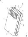
- Fig. 1 shows a plastic housing unit 10 for an electronic device.
- the plastic housing unit 10 includes a plastic housing 13, a heat sink 15, and a layer 18 of elastomer.
- the heat sink 15 is attached to the plastic housing 13 while the elastomer layer 18 is placed between a part of the plastic housing 13 and a part of the heat sink 15.
- An outer surface of the elastomer layer 18 is placed next to a part for the plastic housing 13 while an inner surface of the elastomer layer 18 is placed to a part of the heat sink 15, as better seen in Fig. 8 .
- the plastic housing 13 comprises a plastic first housing portion 21 with a plastic second housing portion 24 and a plastic housing portion living hinge 26.
- the living hinge 26 is also simply called a plastic hinge.
- Each of the first housing portion 21 and the second housing portion 24 has a shape of an open rectangular box with a rim.
- the housing portion living hinge 26 integrally joins the rim of the first housing portion 21 with the rim of the second housing portion 24 such that the first housing portion 21 or the second housing portion 24 can rotate about a longitudinal axis of the housing portion living hinge 26.
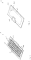
- the first housing portion 21 includes several plastic first housing portion locking elements 29 and a heat sink opening 32.
- the heat sink opening 32 is located at an inner part of the first housing portion 21 while the first housing portion locking elements 29 are located at the rim of the first housing portion 21.
- the heat sink opening 32 includes a rim or edge 35 with a groove.
- the groove extends along the entire rim 35 of the heat sink opening 32.
- the second housing portion 24 includes several plastic second housing portion locking elements, which are located along the rim of the second housing portion 24 and which are adapted for locking with the first housing portion locking elements 29.
- the second housing portion locking elements are not shown in the Figures.
- the second housing portion 24 also includes a plastic service door 38 or cover and a plastic door living hinge 39, which integrally joins the service door 38 to another part of the second housing portion 24.
- the plastic service door 38 includes a door locking element.
- a part of the second housing portion 24 also includes a corresponding door locking element, which is adapted for locking with the door locking element of the service door 38. These locking elements are not shown in the Figures.
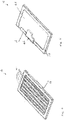
- the heat sink 15 includes a thin and generally rectangular block 40, several parallel fin element portions 41, a housing portion contact part 44, and an electronic device contact area 46.
- the contact part 44 is also called a shoulder.
- the rectangular block 40 comprises an outer major rectangular surface 40o with an inner major rectangular surface 40i and four side minor rectangular surfaces.
- the outer major rectangular surface 40o is shown in Fig. 2 while the inner major rectangular surface 40i is shown in Fig. 3 .
- the side minor rectangular surfaces are not shown in the Figures.
- the inner major surface 40i is located essentially parallel to the outer major surface 40o.
- the four side minor rectangular surfaces form a rectangular loop, which joins the outer major rectangular surface 40o to the inner major rectangular surface 40i.
- Each fin element portion 41 comprises an elongated protrusion.
- the fin element portions 41 are located on the outer major surface 40i.
- the electronic device contact area 46 is located on the inner major surface 40i.
- the housing portion contact part 44 includes an elongated protrusion with a generally rectangular cross-section.
- the elongated protrusion is located next to the four side minor rectangular surfaces and is joined integrally to the side minor rectangular surfaces. In short, the elongated protrusion surrounds the rectangular block 40.
- the heat sink 15 is inserted into the heat sink opening 32 of the first housing portion 21 such that the housing portion contact part 44 of the heat sink 15 is inserted into the groove of the rim 35 of the heat sink opening 32.
- the elastomer layer 18 is located on an outer surface of the housing portion contact part 44.
- the elastomer layer 18 is also located between the housing portion contact part 44 and the groove of the heat sink opening rim 35.
- the inner surface of the elastomer layer 18 is also located next to the housing portion contact part 44 while the outer surface of the elastomer layer 18 is located next to the groove of the heat sink opening rim 35, as seen in Fig. 8 .
- the elastomer layer 18 is provided to separate the housing portion contact part 44 from the groove of the heat sink opening rim 35.
- the heat sink 15 is produced from aluminium using die-casting while the plastic housing 13 is produced from polypropylene (PP), which is filled with talc using insert moulding.
- PP polypropylene
- the plastic housing unit 10 is used for enclosing an electronic device, wherein the plastic housing unit 10 serves to protect and to dissipate heat from the electronic device.
- the electronic device is intended for used in a vehicle, although it can also be used for other applications.
- the groove of the heat sink opening rim 35 of the first housing portion 21 is used for holding the heat sink 15.
- the heat sink opening 32 is used for receiving the heat sink 15 while allowing the heat sink fin element portions 41 to be exposed to external air.
- the electronic device contact area 46 then contacts a heat dissipation area of the vehicle electronic device and receives heat from the electronic device, especially when the electronic device is energised.
- the protrusions of the fin element portions 41 act to increase surface area of the heat sink 15 for improving efficiency of transfer of the heat to external air.
- the elastomer layer 18 acts as a heat barrier or shield between the heat sink 15 and the first housing portion 21.
- the elastomer layer 18 also acts as a cushion for preventing a thermal expansion of the heating heat sink 15 from exerting a force on the first housing portion 21.
- the elastomer layer 18 absorbs this expansion such that the first housing portion 21 does not experience any force or only a little force from the expanded heat sink 15. Without this elastomer layer 18, this expansion can damage the first housing portion 21. In short, the elastomer layer absorbs the thermal expansion of the heat sink 15.
- a method for producing the 10 is described below.
- the method includes a step of producing the heat sink 15 from aluminium using die-casting.
- a step of providing the elastomer layer 18 on the heat sink 15 using over-moulding to form a heat sink sub-assembly is then performed. This step includes placing the heat sink 15 in a mould. The elastomer layer 18 is then placed on the housing portion contact part 44.
- a further step of integrating the heat sink sub-assembly with the plastic housing 13 using insert moulding process is later performed.
- This further step includes placing the heat sink sub-assembly in a further mould.
- Molten polypropylene (PP) which is filled with talc, is then injected into the further mould to form the plastic housing 13, which encloses the heat sink 15.
- the fin element portion 41 are exposed or are not covered with the talc filled PP while the heat sink opening rim 35 covers and encloses the heat sink housing portion contact part 44.
- the plastic housing 13, which is integrated with the heat sink 15 is removed from the mould.
- the integration of the talc filled PP plastic housing 13 with the heat sink 15 is done to provide a single piece without any screws, thereby allowing for production of the plastic housing 13 with the heat sink 15 at a reduced cost.
- the heat sink 15 allows for efficient heat transfer, wherein its surface area is enlarged for improving heat dissipation with ambient air.
- the elastomer layer reduces incompatibility of material between the plastic housing 13 and the heat sink 15, especially in high heat condition.
- the integration of the heat sink 15 with the plastic housing 13 allows for a seamless design for meeting product design requirement.
- the talc filled PP material of the plastic housing 13 acts to reduce cost of the plastic housing 13. scope of the embodiments should be determined by the claims.
Landscapes
- Physics & Mathematics (AREA)
- Thermal Sciences (AREA)
- Engineering & Computer Science (AREA)
- Microelectronics & Electronic Packaging (AREA)
- Casings For Electric Apparatus (AREA)
- Injection Moulding Of Plastics Or The Like (AREA)
Claims (15)
- Gehäuseeinheit (10) für eine elektronische Vorrichtung, die Gehäuseeinheit (10) Folgendes aufweisendeinen Kühlkörper (15) zum Ableiten von Wärme aus der elektronischen Vorrichtung undein Kunststoffgehäuse (13), das talkgefülltes Polypropylen-Material (PP-Material) zum Verbinden mit dem Kühlkörper aufweist,dadurch gekennzeichnet, dassdie Gehäuseeinheit (10) weiterhin mindestens eine Elastomerschicht (18) aufweist, die zwischen mindestens einem Teil des Kühlkörpers (15) und mindestens einem Teil des Kunststoffgehäuses (13) bereitgestellt ist,die Elastomerschicht (18) eingerichtet ist, um zu verhindern, dass das Kunststoffgehäuse (13) eine Dehnungskraft des Kühlkörpers (15) aufnimmt, unddas Kunststoffgehäuse (13) und eine Kühlkörper-Subeinheit, die den Kühlkörper (15) und die mindestens eine Elastomerschicht (18) aufweist, als ein einziges Stück bereitgestellt sind.
- Gehäuseeinheit (10) nach Anspruch 1, wobei der Kühlkörper (15) eine Kontaktfläche (46) mit der elektronischen Vorrichtung aufweist.
- Gehäuseeinheit (10) nach Anspruch 1, wobei das Kunststoffgehäuse (13) einen ersten Kunststoffgehäuseabschnitt (21) mit einem zweiten Kunststoffgehäuseabschnitt (24) und ein Kunststoffscharnier (26) aufweist, das integral mit dem ersten Kunststoffgehäuseabschnitt (21) und mit dem zweiten Kunststoffgehäuseabschnitt (24) verbunden ist.
- Gehäuseeinheit (10) nach Anspruch 3, wobei der erste Kunststoffgehäuseabschnitt (21) und der zweite Kunststoffgehäuseabschnitt (24) einen Kunststoffverriegelungsmechanismus zum Verriegeln des ersten Kunststoffgehäuseabschnitts (21) an dem zweiten Kunststoffgehäuseabschnitt (24) aufweisen.
- Gehäuseeinheit (10) nach Anspruch 3, wobei der erste Kunststoffgehäuseabschnitt (21) eine Öffnung (32) aufweist, die den Kühlkörper (15) aufnimmt.
- Gehäuseeinheit (10) nach Anspruch 5, wobei ein Rand (35) der Öffnung (32) mindestens einen Nutteil aufweist, der den Kühlkörper (15) aufnimmt.
- Gehäuseeinheit (10) nach Anspruch 3, wobei der zweite Kunststoffgehäuseabschnitt (24) eine Zugangsklappe (38) und ein Kunststoffscharnier (39) zum Verbinden der Zugangsklappe (38) mit einem Teil des zweiten Kunststoffgehäuseabschnitts (24) aufweist.
- Gehäuseeinheit (10) nach Anspruch 7, wobei die Zugangsklappe (38) und ein Teil des zweiten Kunststoffgehäuseabschnitts (24) einen Kunststoffverriegelungsmechanismus zum Verriegeln der Zugangsklappe (38) an dem Teil des zweiten Kunststoffgehäuseabschnitts (24) aufweisen.
- Gehäuseeinheit (10) nach Anspruch 1, wobei das Kunststoffgehäuse (13) unter Verwendung von Insert-Formen mit dem Kühlkörper (15) und der mindestens einen Elastomerschicht (18) integriert ist.
- Gehäuseeinheit (10) nach Anspruch 1, wobei die Elastomerschicht (18) unter Verwendung von Überspritzen auf dem Kühlkörper (15) bereitgestellt wird.
- Gehäuseeinheit (10) nach Anspruch 1, wobei der Kühlkörper (15) unter Verwendung von Druckgießen aus einem Metall ausgebildet wird.
- Verfahren zum Herstellen einer Gehäuseeinheit (10) für eine elektronische Vorrichtung, das Verfahren Folgendes aufweisendBereitstellen eines Kühlkörpers (15),Bereitstellen mindestens einer Elastomerschicht (18) auf mindestens einem Teil des Kühlkörpers (15), um eine Kühlkörper-Subeinheit auszubilden,Bereitstellen eines Kunststoffgehäuses (13), das talkgefülltes Polypropylen-Material (PP-Material) aufweist,Integrieren der Kühlkörper-Subeinheit mit dem Kunststoffgehäuse (13), so dass ein einziges Stück bereitgestellt wird,wobei die Elastomerschicht (18) zwischen dem mindestens einen Teil des Kühlkörpers (15) und dem Kunststoffgehäuse (13) bereitgestellt wird undwobei die Elastomerschicht (18) verhindert, dass das Kunststoffgehäuse (13) eine Dehnungskraft des Kühlkörpers (15) aufnimmt.
- Verfahren nach Anspruch 12, wobei der Kühlkörper (15) unter Verwendung von Druckgießen aus einem Metall bereitgestellt wird.
- Verfahren nach Anspruch 12, wobei die Elastomerschicht (18) unter Verwendung von Überspritzen auf dem Kühlkörper (15) bereitgestellt wird.
- Verfahren nach Anspruch 12, wobei das Kunststoffgehäuse (13) unter Verwendung von Insert-Formen mit dem Kühlkörper (15) integriert ist, der die mindestens eine Elastomerschicht (18) aufweist.
Applications Claiming Priority (1)
| Application Number | Priority Date | Filing Date | Title |
|---|---|---|---|
| PCT/IB2016/052715 WO2017194996A1 (en) | 2016-05-12 | 2016-05-12 | Integrated aluminum heat sink, elastomer on talc filled pp housing for electronic module |
Publications (3)
| Publication Number | Publication Date |
|---|---|
| EP3456162A1 EP3456162A1 (de) | 2019-03-20 |
| EP3456162A4 EP3456162A4 (de) | 2020-01-08 |
| EP3456162B1 true EP3456162B1 (de) | 2022-11-09 |
Family
ID=60266489
Family Applications (1)
| Application Number | Title | Priority Date | Filing Date |
|---|---|---|---|
| EP16901569.0A Active EP3456162B1 (de) | 2016-05-12 | 2016-05-12 | Gehäuse mit talkgefülltem pp und integriertem aluminiumkühlkörper mit elastomerschichten für elektronisches modul |
Country Status (2)
| Country | Link |
|---|---|
| EP (1) | EP3456162B1 (de) |
| WO (1) | WO2017194996A1 (de) |
Cited By (1)
| Publication number | Priority date | Publication date | Assignee | Title |
|---|---|---|---|---|
| IT202300008649A1 (it) * | 2023-05-03 | 2024-11-03 | Taco Italia S R L | Motore elettrico con sistema di dissipazione di calore |
Family Cites Families (7)
| Publication number | Priority date | Publication date | Assignee | Title |
|---|---|---|---|---|
| US5212627A (en) * | 1992-01-31 | 1993-05-18 | Motorola, Inc. | Electronic module housing and assembly with integral heatsink |
| US6741089B2 (en) * | 2002-01-14 | 2004-05-25 | Micro Control Company | Hinged heat sink burn-in socket |
| JP3994810B2 (ja) * | 2002-07-09 | 2007-10-24 | 住友電装株式会社 | バッテリーヒューズを内蔵したボックス |
| US7355857B2 (en) * | 2006-02-07 | 2008-04-08 | Methode Electronics, Inc. | Heat sink gasket |
| US7845395B2 (en) * | 2007-07-02 | 2010-12-07 | Cooler Master Co., Ltd. | Heat-dissipating casing structure |
| JP2011091167A (ja) * | 2009-10-21 | 2011-05-06 | Yazaki Corp | 発熱部品収納体 |
| US9007773B2 (en) * | 2012-08-31 | 2015-04-14 | Flextronics Ap, Llc | Housing unit with heat sink |
-
2016
- 2016-05-12 WO PCT/IB2016/052715 patent/WO2017194996A1/en not_active Ceased
- 2016-05-12 EP EP16901569.0A patent/EP3456162B1/de active Active
Cited By (2)
| Publication number | Priority date | Publication date | Assignee | Title |
|---|---|---|---|---|
| IT202300008649A1 (it) * | 2023-05-03 | 2024-11-03 | Taco Italia S R L | Motore elettrico con sistema di dissipazione di calore |
| EP4459851A1 (de) * | 2023-05-03 | 2024-11-06 | TACO ITALIA S.r.l. | Elektromotor mit wärmeabfuhrsystem |
Also Published As
| Publication number | Publication date |
|---|---|
| EP3456162A4 (de) | 2020-01-08 |
| WO2017194996A1 (en) | 2017-11-16 |
| EP3456162A1 (de) | 2019-03-20 |
Similar Documents
| Publication | Publication Date | Title |
|---|---|---|
| US10888031B2 (en) | Memory device with memory modules located within liquid coolant chamber | |
| KR101428933B1 (ko) | 방열판을 이용한 차량의 전자 제어 장치 및 그 제조 방법 | |
| US6377219B2 (en) | Composite molded antenna assembly | |
| JP6494645B2 (ja) | 包囲及びスペーサ(sas)構造を備える熱電ヒートポンプ | |
| US6651732B2 (en) | Thermally conductive elastomeric heat dissipation assembly with snap-in heat transfer conduit | |
| CN1222053C (zh) | 热电变换装置 | |
| US20190067656A1 (en) | Frame and battery module | |
| US10111363B2 (en) | System for effectively transfering heat from electronic devices and method for forming the same | |
| KR102335853B1 (ko) | 수지 몰드 금형 및 수지 몰드 방법 | |
| JP2012512545A (ja) | 封止された端部を有するソーラーモジュール | |
| CN110662372A (zh) | 电子单元及其制造方法 | |
| EP3456162B1 (de) | Gehäuse mit talkgefülltem pp und integriertem aluminiumkühlkörper mit elastomerschichten für elektronisches modul | |
| JP2025516690A (ja) | 冷却系アレンジメント、制御手段、ヒートシンク並びにその製造方法 | |
| US20130228311A1 (en) | Heat-dissipating assembly and method for manufacturing the same | |
| CN208143100U (zh) | 电容器直接冷却方式的逆变器 | |
| JP4382396B2 (ja) | 電磁波シールド筐体の製造方法 | |
| KR101821588B1 (ko) | 방열 성능을 개선한 연료펌프 모듈 및 이를 제조하는 연료펌프 모듈 제조방법 | |
| KR20190110695A (ko) | 컨버터 냉각장치 및 이를 구비한 자동차 | |
| KR101597947B1 (ko) | 열전소자를 구비한 냉각모듈 | |
| US20150129174A1 (en) | Component reachable expandable heat plate | |
| KR20190000952A (ko) | 케이스 및 이의 설치방법 | |
| CN207504079U (zh) | 电子设备 | |
| KR101846204B1 (ko) | 내부 방열핀을 구비한 전자 제어 장치 | |
| KR20190110700A (ko) | 컨버터 냉각장치 및 이를 구비한 자동차 | |
| CN109114524A (zh) | 一种led灯外壳及一种应用该led灯外壳的led灯 |
Legal Events
| Date | Code | Title | Description |
|---|---|---|---|
| STAA | Information on the status of an ep patent application or granted ep patent |
Free format text: STATUS: THE INTERNATIONAL PUBLICATION HAS BEEN MADE |
|
| PUAI | Public reference made under article 153(3) epc to a published international application that has entered the european phase |
Free format text: ORIGINAL CODE: 0009012 |
|
| STAA | Information on the status of an ep patent application or granted ep patent |
Free format text: STATUS: REQUEST FOR EXAMINATION WAS MADE |
|
| 17P | Request for examination filed |
Effective date: 20181212 |
|
| AK | Designated contracting states |
Kind code of ref document: A1 Designated state(s): AL AT BE BG CH CY CZ DE DK EE ES FI FR GB GR HR HU IE IS IT LI LT LU LV MC MK MT NL NO PL PT RO RS SE SI SK SM TR |
|
| AX | Request for extension of the european patent |
Extension state: BA ME |
|
| DAV | Request for validation of the european patent (deleted) | ||
| DAX | Request for extension of the european patent (deleted) | ||
| A4 | Supplementary search report drawn up and despatched |
Effective date: 20191209 |
|
| RIC1 | Information provided on ipc code assigned before grant |
Ipc: H05K 7/20 20060101AFI20191203BHEP Ipc: H05K 5/00 20060101ALI20191203BHEP |
|
| RAP1 | Party data changed (applicant data changed or rights of an application transferred) |
Owner name: CONTINENTAL AUTOMOTIVE GMBH |
|
| GRAP | Despatch of communication of intention to grant a patent |
Free format text: ORIGINAL CODE: EPIDOSNIGR1 |
|
| STAA | Information on the status of an ep patent application or granted ep patent |
Free format text: STATUS: GRANT OF PATENT IS INTENDED |
|
| INTG | Intention to grant announced |
Effective date: 20220221 |
|
| GRAJ | Information related to disapproval of communication of intention to grant by the applicant or resumption of examination proceedings by the epo deleted |
Free format text: ORIGINAL CODE: EPIDOSDIGR1 |
|
| STAA | Information on the status of an ep patent application or granted ep patent |
Free format text: STATUS: REQUEST FOR EXAMINATION WAS MADE |
|
| INTC | Intention to grant announced (deleted) | ||
| GRAP | Despatch of communication of intention to grant a patent |
Free format text: ORIGINAL CODE: EPIDOSNIGR1 |
|
| STAA | Information on the status of an ep patent application or granted ep patent |
Free format text: STATUS: GRANT OF PATENT IS INTENDED |
|
| INTG | Intention to grant announced |
Effective date: 20220601 |
|
| RAP1 | Party data changed (applicant data changed or rights of an application transferred) |
Owner name: CONTINENTAL AUTOMOTIVE TECHNOLOGIES GMBH |
|
| GRAS | Grant fee paid |
Free format text: ORIGINAL CODE: EPIDOSNIGR3 |
|
| GRAA | (expected) grant |
Free format text: ORIGINAL CODE: 0009210 |
|
| STAA | Information on the status of an ep patent application or granted ep patent |
Free format text: STATUS: THE PATENT HAS BEEN GRANTED |
|
| AK | Designated contracting states |
Kind code of ref document: B1 Designated state(s): AL AT BE BG CH CY CZ DE DK EE ES FI FR GB GR HR HU IE IS IT LI LT LU LV MC MK MT NL NO PL PT RO RS SE SI SK SM TR |
|
| REG | Reference to a national code |
Ref country code: GB Ref legal event code: FG4D |
|
| REG | Reference to a national code |
Ref country code: CH Ref legal event code: EP Ref country code: AT Ref legal event code: REF Ref document number: 1531170 Country of ref document: AT Kind code of ref document: T Effective date: 20221115 |
|
| REG | Reference to a national code |
Ref country code: DE Ref legal event code: R096 Ref document number: 602016076290 Country of ref document: DE |
|
| REG | Reference to a national code |
Ref country code: IE Ref legal event code: FG4D |
|
| REG | Reference to a national code |
Ref country code: LT Ref legal event code: MG9D |
|
| REG | Reference to a national code |
Ref country code: NL Ref legal event code: MP Effective date: 20221109 |
|
| REG | Reference to a national code |
Ref country code: AT Ref legal event code: MK05 Ref document number: 1531170 Country of ref document: AT Kind code of ref document: T Effective date: 20221109 |
|
| PG25 | Lapsed in a contracting state [announced via postgrant information from national office to epo] |
Ref country code: SE Free format text: LAPSE BECAUSE OF FAILURE TO SUBMIT A TRANSLATION OF THE DESCRIPTION OR TO PAY THE FEE WITHIN THE PRESCRIBED TIME-LIMIT Effective date: 20221109 Ref country code: PT Free format text: LAPSE BECAUSE OF FAILURE TO SUBMIT A TRANSLATION OF THE DESCRIPTION OR TO PAY THE FEE WITHIN THE PRESCRIBED TIME-LIMIT Effective date: 20230309 Ref country code: NO Free format text: LAPSE BECAUSE OF FAILURE TO SUBMIT A TRANSLATION OF THE DESCRIPTION OR TO PAY THE FEE WITHIN THE PRESCRIBED TIME-LIMIT Effective date: 20230209 Ref country code: LT Free format text: LAPSE BECAUSE OF FAILURE TO SUBMIT A TRANSLATION OF THE DESCRIPTION OR TO PAY THE FEE WITHIN THE PRESCRIBED TIME-LIMIT Effective date: 20221109 Ref country code: FI Free format text: LAPSE BECAUSE OF FAILURE TO SUBMIT A TRANSLATION OF THE DESCRIPTION OR TO PAY THE FEE WITHIN THE PRESCRIBED TIME-LIMIT Effective date: 20221109 Ref country code: ES Free format text: LAPSE BECAUSE OF FAILURE TO SUBMIT A TRANSLATION OF THE DESCRIPTION OR TO PAY THE FEE WITHIN THE PRESCRIBED TIME-LIMIT Effective date: 20221109 Ref country code: AT Free format text: LAPSE BECAUSE OF FAILURE TO SUBMIT A TRANSLATION OF THE DESCRIPTION OR TO PAY THE FEE WITHIN THE PRESCRIBED TIME-LIMIT Effective date: 20221109 |
|
| PG25 | Lapsed in a contracting state [announced via postgrant information from national office to epo] |
Ref country code: RS Free format text: LAPSE BECAUSE OF FAILURE TO SUBMIT A TRANSLATION OF THE DESCRIPTION OR TO PAY THE FEE WITHIN THE PRESCRIBED TIME-LIMIT Effective date: 20221109 Ref country code: PL Free format text: LAPSE BECAUSE OF FAILURE TO SUBMIT A TRANSLATION OF THE DESCRIPTION OR TO PAY THE FEE WITHIN THE PRESCRIBED TIME-LIMIT Effective date: 20221109 Ref country code: LV Free format text: LAPSE BECAUSE OF FAILURE TO SUBMIT A TRANSLATION OF THE DESCRIPTION OR TO PAY THE FEE WITHIN THE PRESCRIBED TIME-LIMIT Effective date: 20221109 Ref country code: IS Free format text: LAPSE BECAUSE OF FAILURE TO SUBMIT A TRANSLATION OF THE DESCRIPTION OR TO PAY THE FEE WITHIN THE PRESCRIBED TIME-LIMIT Effective date: 20230309 Ref country code: HR Free format text: LAPSE BECAUSE OF FAILURE TO SUBMIT A TRANSLATION OF THE DESCRIPTION OR TO PAY THE FEE WITHIN THE PRESCRIBED TIME-LIMIT Effective date: 20221109 Ref country code: GR Free format text: LAPSE BECAUSE OF FAILURE TO SUBMIT A TRANSLATION OF THE DESCRIPTION OR TO PAY THE FEE WITHIN THE PRESCRIBED TIME-LIMIT Effective date: 20230210 |
|
| PG25 | Lapsed in a contracting state [announced via postgrant information from national office to epo] |
Ref country code: NL Free format text: LAPSE BECAUSE OF FAILURE TO SUBMIT A TRANSLATION OF THE DESCRIPTION OR TO PAY THE FEE WITHIN THE PRESCRIBED TIME-LIMIT Effective date: 20221109 |
|
| PG25 | Lapsed in a contracting state [announced via postgrant information from national office to epo] |
Ref country code: SM Free format text: LAPSE BECAUSE OF FAILURE TO SUBMIT A TRANSLATION OF THE DESCRIPTION OR TO PAY THE FEE WITHIN THE PRESCRIBED TIME-LIMIT Effective date: 20221109 Ref country code: RO Free format text: LAPSE BECAUSE OF FAILURE TO SUBMIT A TRANSLATION OF THE DESCRIPTION OR TO PAY THE FEE WITHIN THE PRESCRIBED TIME-LIMIT Effective date: 20221109 Ref country code: EE Free format text: LAPSE BECAUSE OF FAILURE TO SUBMIT A TRANSLATION OF THE DESCRIPTION OR TO PAY THE FEE WITHIN THE PRESCRIBED TIME-LIMIT Effective date: 20221109 Ref country code: DK Free format text: LAPSE BECAUSE OF FAILURE TO SUBMIT A TRANSLATION OF THE DESCRIPTION OR TO PAY THE FEE WITHIN THE PRESCRIBED TIME-LIMIT Effective date: 20221109 Ref country code: CZ Free format text: LAPSE BECAUSE OF FAILURE TO SUBMIT A TRANSLATION OF THE DESCRIPTION OR TO PAY THE FEE WITHIN THE PRESCRIBED TIME-LIMIT Effective date: 20221109 |
|
| REG | Reference to a national code |
Ref country code: DE Ref legal event code: R097 Ref document number: 602016076290 Country of ref document: DE |
|
| PG25 | Lapsed in a contracting state [announced via postgrant information from national office to epo] |
Ref country code: SK Free format text: LAPSE BECAUSE OF FAILURE TO SUBMIT A TRANSLATION OF THE DESCRIPTION OR TO PAY THE FEE WITHIN THE PRESCRIBED TIME-LIMIT Effective date: 20221109 Ref country code: AL Free format text: LAPSE BECAUSE OF FAILURE TO SUBMIT A TRANSLATION OF THE DESCRIPTION OR TO PAY THE FEE WITHIN THE PRESCRIBED TIME-LIMIT Effective date: 20221109 |
|
| PLBE | No opposition filed within time limit |
Free format text: ORIGINAL CODE: 0009261 |
|
| STAA | Information on the status of an ep patent application or granted ep patent |
Free format text: STATUS: NO OPPOSITION FILED WITHIN TIME LIMIT |
|
| 26N | No opposition filed |
Effective date: 20230810 |
|
| PG25 | Lapsed in a contracting state [announced via postgrant information from national office to epo] |
Ref country code: SI Free format text: LAPSE BECAUSE OF FAILURE TO SUBMIT A TRANSLATION OF THE DESCRIPTION OR TO PAY THE FEE WITHIN THE PRESCRIBED TIME-LIMIT Effective date: 20221109 |
|
| REG | Reference to a national code |
Ref country code: CH Ref legal event code: PL |
|
| PG25 | Lapsed in a contracting state [announced via postgrant information from national office to epo] |
Ref country code: MC Free format text: LAPSE BECAUSE OF FAILURE TO SUBMIT A TRANSLATION OF THE DESCRIPTION OR TO PAY THE FEE WITHIN THE PRESCRIBED TIME-LIMIT Effective date: 20221109 |
|
| GBPC | Gb: european patent ceased through non-payment of renewal fee |
Effective date: 20230512 |
|
| REG | Reference to a national code |
Ref country code: BE Ref legal event code: MM Effective date: 20230531 |
|
| PG25 | Lapsed in a contracting state [announced via postgrant information from national office to epo] |
Ref country code: MC Free format text: LAPSE BECAUSE OF FAILURE TO SUBMIT A TRANSLATION OF THE DESCRIPTION OR TO PAY THE FEE WITHIN THE PRESCRIBED TIME-LIMIT Effective date: 20221109 Ref country code: LU Free format text: LAPSE BECAUSE OF NON-PAYMENT OF DUE FEES Effective date: 20230512 Ref country code: LI Free format text: LAPSE BECAUSE OF NON-PAYMENT OF DUE FEES Effective date: 20230531 Ref country code: CH Free format text: LAPSE BECAUSE OF NON-PAYMENT OF DUE FEES Effective date: 20230531 |
|
| REG | Reference to a national code |
Ref country code: DE Ref legal event code: R081 Ref document number: 602016076290 Country of ref document: DE Owner name: CONTINENTAL AUTOMOTIVE TECHNOLOGIES GMBH, DE Free format text: FORMER OWNER: CONTINENTAL AUTOMOTIVE TECHNOLOGIES GMBH, 30165 HANNOVER, DE Ref country code: DE Ref legal event code: R081 Ref document number: 602016076290 Country of ref document: DE Owner name: AUMOVIO GERMANY GMBH, DE Free format text: FORMER OWNER: CONTINENTAL AUTOMOTIVE TECHNOLOGIES GMBH, 30165 HANNOVER, DE |
|
| REG | Reference to a national code |
Ref country code: IE Ref legal event code: MM4A |
|
| PG25 | Lapsed in a contracting state [announced via postgrant information from national office to epo] |
Ref country code: IE Free format text: LAPSE BECAUSE OF NON-PAYMENT OF DUE FEES Effective date: 20230512 |
|
| PG25 | Lapsed in a contracting state [announced via postgrant information from national office to epo] |
Ref country code: IE Free format text: LAPSE BECAUSE OF NON-PAYMENT OF DUE FEES Effective date: 20230512 Ref country code: GB Free format text: LAPSE BECAUSE OF NON-PAYMENT OF DUE FEES Effective date: 20230512 |
|
| PG25 | Lapsed in a contracting state [announced via postgrant information from national office to epo] |
Ref country code: IT Free format text: LAPSE BECAUSE OF FAILURE TO SUBMIT A TRANSLATION OF THE DESCRIPTION OR TO PAY THE FEE WITHIN THE PRESCRIBED TIME-LIMIT Effective date: 20221109 Ref country code: BE Free format text: LAPSE BECAUSE OF NON-PAYMENT OF DUE FEES Effective date: 20230531 |
|
| PG25 | Lapsed in a contracting state [announced via postgrant information from national office to epo] |
Ref country code: BG Free format text: LAPSE BECAUSE OF FAILURE TO SUBMIT A TRANSLATION OF THE DESCRIPTION OR TO PAY THE FEE WITHIN THE PRESCRIBED TIME-LIMIT Effective date: 20221109 |
|
| PG25 | Lapsed in a contracting state [announced via postgrant information from national office to epo] |
Ref country code: BG Free format text: LAPSE BECAUSE OF FAILURE TO SUBMIT A TRANSLATION OF THE DESCRIPTION OR TO PAY THE FEE WITHIN THE PRESCRIBED TIME-LIMIT Effective date: 20221109 |
|
| PGFP | Annual fee paid to national office [announced via postgrant information from national office to epo] |
Ref country code: DE Payment date: 20250531 Year of fee payment: 10 |
|
| PGFP | Annual fee paid to national office [announced via postgrant information from national office to epo] |
Ref country code: FR Payment date: 20250528 Year of fee payment: 10 |
|
| PG25 | Lapsed in a contracting state [announced via postgrant information from national office to epo] |
Ref country code: CY Free format text: LAPSE BECAUSE OF FAILURE TO SUBMIT A TRANSLATION OF THE DESCRIPTION OR TO PAY THE FEE WITHIN THE PRESCRIBED TIME-LIMIT; INVALID AB INITIO Effective date: 20160512 |
|
| PG25 | Lapsed in a contracting state [announced via postgrant information from national office to epo] |
Ref country code: HU Free format text: LAPSE BECAUSE OF FAILURE TO SUBMIT A TRANSLATION OF THE DESCRIPTION OR TO PAY THE FEE WITHIN THE PRESCRIBED TIME-LIMIT; INVALID AB INITIO Effective date: 20160512 |
|
| PG25 | Lapsed in a contracting state [announced via postgrant information from national office to epo] |
Ref country code: TR Free format text: LAPSE BECAUSE OF FAILURE TO SUBMIT A TRANSLATION OF THE DESCRIPTION OR TO PAY THE FEE WITHIN THE PRESCRIBED TIME-LIMIT Effective date: 20221109 |
|
| REG | Reference to a national code |
Ref country code: DE Ref legal event code: R081 Ref document number: 602016076290 Country of ref document: DE Owner name: AUMOVIO GERMANY GMBH, DE Free format text: FORMER OWNER: CONTINENTAL AUTOMOTIVE TECHNOLOGIES GMBH, 30175 HANNOVER, DE |