EP3455449B1 - Tiefenkompensierter aktuator und verwendung davon in verbindung mit einem transportablen tauchbewegungsausgleicher - Google Patents
Tiefenkompensierter aktuator und verwendung davon in verbindung mit einem transportablen tauchbewegungsausgleicher Download PDFInfo
- Publication number
- EP3455449B1 EP3455449B1 EP17796464.0A EP17796464A EP3455449B1 EP 3455449 B1 EP3455449 B1 EP 3455449B1 EP 17796464 A EP17796464 A EP 17796464A EP 3455449 B1 EP3455449 B1 EP 3455449B1
- Authority
- EP
- European Patent Office
- Prior art keywords
- cylinder
- piston
- volume
- actuator
- rod
- Prior art date
- Legal status (The legal status is an assumption and is not a legal conclusion. Google has not performed a legal analysis and makes no representation as to the accuracy of the status listed.)
- Active
Links
Images


Classifications
-
- E—FIXED CONSTRUCTIONS
- E21—EARTH OR ROCK DRILLING; MINING
- E21B—EARTH OR ROCK DRILLING; OBTAINING OIL, GAS, WATER, SOLUBLE OR MELTABLE MATERIALS OR A SLURRY OF MINERALS FROM WELLS
- E21B19/00—Handling rods, casings, tubes or the like outside the borehole, e.g. in the derrick; Apparatus for feeding the rods or cables
- E21B19/002—Handling rods, casings, tubes or the like outside the borehole, e.g. in the derrick; Apparatus for feeding the rods or cables specially adapted for underwater drilling
- E21B19/004—Handling rods, casings, tubes or the like outside the borehole, e.g. in the derrick; Apparatus for feeding the rods or cables specially adapted for underwater drilling supporting a riser from a drilling or production platform
- E21B19/006—Handling rods, casings, tubes or the like outside the borehole, e.g. in the derrick; Apparatus for feeding the rods or cables specially adapted for underwater drilling supporting a riser from a drilling or production platform including heave compensators
-
- B—PERFORMING OPERATIONS; TRANSPORTING
- B66—HOISTING; LIFTING; HAULING
- B66C—CRANES; LOAD-ENGAGING ELEMENTS OR DEVICES FOR CRANES, CAPSTANS, WINCHES, OR TACKLES
- B66C13/00—Other constructional features or details
- B66C13/02—Devices for facilitating retrieval of floating objects, e.g. for recovering crafts from water
-
- B—PERFORMING OPERATIONS; TRANSPORTING
- B66—HOISTING; LIFTING; HAULING
- B66C—CRANES; LOAD-ENGAGING ELEMENTS OR DEVICES FOR CRANES, CAPSTANS, WINCHES, OR TACKLES
- B66C13/00—Other constructional features or details
- B66C13/04—Auxiliary devices for controlling movements of suspended loads, or preventing cable slack
-
- F—MECHANICAL ENGINEERING; LIGHTING; HEATING; WEAPONS; BLASTING
- F15—FLUID-PRESSURE ACTUATORS; HYDRAULICS OR PNEUMATICS IN GENERAL
- F15B—SYSTEMS ACTING BY MEANS OF FLUIDS IN GENERAL; FLUID-PRESSURE ACTUATORS, e.g. SERVOMOTORS; DETAILS OF FLUID-PRESSURE SYSTEMS, NOT OTHERWISE PROVIDED FOR
- F15B21/00—Common features of fluid actuator systems; Fluid-pressure actuator systems or details thereof, not covered by any other group of this subclass
- F15B21/006—Compensation or avoidance of ambient pressure variation
Definitions
- the present invention relates to a system comprising a depth compensated actuator and a gas accumulator.
- the system is intended for subsea use, compensating for variation in appearing water pressure.
- the invention relates to a depth compensated actuator suitable for subsea lifting operations, comprising an actuator comprising a cylinder-shaped body and a piston with a piston rod, able to reciprocate inside the cylinder, connection means associated with the cylinder, the heave compensator also comprises volumes intended to contain a fluid, and with an arrangement provided with surface intended to be exposed to external water pressure effect.
- US 2008/0251980 A1 relates to a depth compensated passive heave compensator.
- This prior art heave compensator consists of three major components: an actuator device; an accumulator and a depth compensator.
- the actuator consists of a first cylinder provided with a piston and piston rod, the first cylinder being connected directly or by means of a crane at its upper end to a vessel.
- the piston rod extends from a piston located within the first cylinder through the lower end thereof and is connected to subsea equipment or a payload to be lifted or lowered.
- the accumulator consists of a second cylinder containing a movable piston
- the depth compensator consists of a third cylinder containing a movable piston and a piston rod, the piston rod extending down through the lower end of the cylinder and is provided with a surface exposed to the surrounding water pressure.
- the upper volume of the actuator is in fluid communication with the upper volume of depth compensator
- the lower volume of the actuator is in fluid communication with the volume beneath the piston of the accumulator.
- WO 2017/146591 discloses a mobile active heave compensator provided with an attachment device for suspending the compensator from a load bearing device and an attachment device for carrying a payload.
- the compensator comprises a passive heave compensation part and an active heave compensation part and is associated with a sensor arrangement producing input signals for a control unit and a power source.
- the compensator incorporates a hydraulic fluid pump and/or motor device, affecting the active heave compensating part, producing output signal(s) to the hydraulic fluid and/or motor device to transport the hydraulic fluid as required, based on input signals received from the sensor arrangement.
- the prior art compensation is performed utilizing a pressure intensifier principle in the form of an external cylinder to compensate the effect of the water pressure acting on the piston rod.
- This requires a second hydraulic cylinder the depth compensator) connected to the main hydraulic cylinder (actuator).
- the main disadvantages of the prior art are:
- the main difference between the prior art and the system according to the present invention is the way and manner the depth compensation is obtained, as well as the possibility of using active rod control. According to the present invention a different way and devices for providing depth compensating devices intended to be integrated with an actuator is provided.
- the actuator the depth compensator and the accumulator comprise cylinders, pistons and integrated piston rods fixed to the pistons, the pistons being movably arranged inside the respective cylinder, while at least one end of the depth compensator rod extends out through an end closure of the cylinder, the free end of the rod having a surface, exposed to the surrounding water pressure.
- an actuator, depth compensator, and gas accumulator are provided to obtain an efficient and effective combination, forming an integrated, slender and efficient unit, for example suitable for use as a subsea heave compensator.
- high pressure means pressures up to 500 bar or more, while low pressure or vacuum means pressures below 2 bar.
- An object of the present invention is to provide a system comprising a depth compensated actuator where the overall size, slenderness, and/or weight of the compensator, such as the added weight of the compensation cylinder and possible pressure intensifier devices required and volume of required hydraulic fluid are significantly reduced compared with the prior art compensators.
- Another object of the invention is to provide a system with reduced inherent friction in the system, i.e. friction for example caused by hydraulic seals and/or transfer of fluid in the system, and friction and added inertia of the moving parts of the compensator.
- Another object of the invention is to provide a system with a depth compensated actuator with a free pressure area that can be utilized as part of an active heave compensator.
- Yet another object of the invention is to develop and improve the depth compensated actuator and/or the depth compensator unit configuration to significantly reduce the required size and weight of the unit, limiting the size of working volumes that must be filled with oil, without reducing the capacity or efficiency of the system. Friction is also smaller as the seal size is significantly reduced.
- a further object of the invention is to provide an embodiment of a system comprising a depth compensated actuator, suitable to be used as an integrated part of a heave compensator.
- a system comprising a depth compensated actuator and a gas accumulator, wherein the system with the depth compensated actuator and the gas accumulator is suitable to form a part for example of a transportable inline depth compensated heave compensator for subsea lifting or loading operations, comprising a hollow rod actuator comprising a first cylinder, a first ring piston with a hollow rod actuator and a second cylinder mounted concentric with the first cylinder and fastened to an upper end of the cylinder, the ring piston is adapted to slide on the outer diameter of the second cylinder; a first volume is formed by the outer diameter of the hollow rod, the lower end of the first cylinder, the inner diameter of the first cylinder and the ring piston, and may be filled with oil or gas; a second volume is formed by the outer diameter of the second cylinder, the upper end of the first cylinder, the inner diameter of the first cylinder and the ring piston, and may be filled with oil, gas or be under vacuum; a third volume is formed by
- the conduit means may connect a volume in the hollow actuator piston rod and a volume in the hollow depth compensator piston rod.
- the conduit means may connect the volume at the closed end of the actuator and the closed volume of the piston in the compensator, both opposite side of the piston rod.
- the system may be used in subsea conditions, and the actuator may be a high-pressure depth compensated actuator and comprises is a hollow rod actuator and where the depth compensating is:
- the system may be configured wherein the volume of the hollow piston rod of the actuator communicates with the volume in the hollow rod of the depth compensator through a stationary cylinder inside the actuator cylinder and a stationary cylinder inside the depth compensator cylinder.
- the piston rod of the depth compensator may be ring shaped and may be provided with a stroke limiting device.
- the cylinder of the depth compensator is open downwards and that the inner diameter of the open-ended cylinder corresponds to outer diameter of the hollow piston rod.
- the cross-sectional area of the hollow piston of the depth compensator exposed to the surrounding water is larger than the corresponding exposed area of the actuator.
- the system may comprise:
- Said depth compensated actuator may further be configured in such way that the area ratio between the ring-shaped piston and the ring-shaped piston rod is equal to or smaller than the area ratio between the piston and the piston rod.
- the depth compensator may further consist of a third cylinder; a piston exposed to external pressure; a piston rod connected to the piston and adapted for reciprocation inside the third cylinder; a fourth cylinder, mounted concentrically with the third cylinder at the lower end of the third cylinder; forming a fourth volume V4 between the lower end of the fourth cylinder , the inner diameter of the fourth cylinder, the lower end of the third cylinder and displaced by the piston rod, which may be filled with oil; forming a fifth V5 volume between the lower end of the third cylinder, the inner diameter of the third cylinder, lower end of the piston and the outer diameter of the piston rod, which may be filled with gas or be under vacuum; and conduit means between the fourth volume V4 and the third volume V3.
- the depth compensator may be a depth compensator further consisting of a third cylinder; a piston; a piston rod exposed to external pressure connected to the piston and adapted for reciprocation inside the third cylinder; forming a fifth V5 volume between the lower end of the third cylinder, the inner diameter of the third cylinder, lower end of the piston and the outer diameter of the piston rod, which may be filled with gas or be under vacuum; forming a sixth volume V6 between the upper end of the third cylinder, the inner diameter of the third cylinder and the upper end of the piston which may be filled with oil; and a conduit means between the sixth volume V6 and the second volume V2.
- oil is replaced by any fluid and/or gas is replaced by any fluid and/or vacuum is replaced by any fluid/gas.
- HPDCA high-pressure depth compensated actuator
- the HPDCA uses a hollow rod actuator to significantly reduce the required size and weight of the depth compensator as only the volume of the hollow piston must be filled with oil. Friction is also much smaller as the seal size is significantly reduced (from full actuator diameter to the inside diameter of the hollow piston rod). The required amount of oil flow is also significantly lower than for the prior art solutions.
- actuators or depth compensators are from a simplicity point of view not always disclosed or indicated.
- Typical elements associated with a system such as seals, accumulators, other types of pressure intensifiers, pumps, valves, control systems are not disclosed in detail.
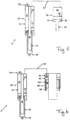
- Figure 1 discloses schematically an illustration of a prior art depth compensated actuator incorporated in a heave compensator for subsea use.
- the parts disclosed are a conventional actuator consisting of a cylinder, a piston 2 reciprocally arranged inside the cylinder 1 and a piston rod 3 rigidly fixed to the piston 2.
- the piston 2 establishes two different volumes in the cylinder 1.
- the actuator 1 is provided with a first connection means 8 while the free end of the piston rod 3 is provided with a second connection means 9.
- the first connection means 8 is configured to be connected to a crane or the like (not shown), while the second connection means 9 is configured to be fixed to a payload (not shown) to be installed on the seabed.
- the actuator is fluidly communicating with a depth compensator 20, consisting of a cylinder 21 and a piston 22, reciprocally arranged inside the depth compensator 20.
- a piston rod 23 is fixed to the piston 22, the piston rod 23 extending out through the bottom closure of the cylinder 21, having an end surface exposed to the surrounding water pressure.
- the upper volume of the depth compensator is in fluid communication with the upper volume of the actuator.
- the system disclosed in Figure 1 also consist of a gas accumulator consisting of a cylinder and a piston reciprocally arranged inside the cylinder, splitting the cylinder into an upper and lower volume.
- the lower volume of the accumulator is in fluid communication with the lower volume of the actuator.
- Figure 2 discloses schematically an illustration of one embodiment of a system according to the present invention with a depth compensated actuator 0 that is forming a part of an active heave compensator, disclosing how to implement active control of the actuator rod, i.e. the active heave compensation.
- the depth compensated actuator 0 disclosed in Figure 2 corresponds to the example disclosed in Figure 5 and will be described in further detail below.
- the following components are added compared to depth compensated actuator 0 disclosed in Figure 5 :
- An active heave compensator comprises an actuator connected to one or more accumulators, which further may be connected to one or more gas tanks.
- the accumulator shown allows for very efficient use of commercially available hydraulic motors, used to gain active control the hydraulic actuator.
- Automatic control of the hydraulic actuator is used to compensate for heave motion.
- the automatic control is controlled by a computer that calculates the control signal based on measurements from several sensors, where the most important ones are the piston position sensor, the accelerometer and the wire rope speed sensor. Information about the wire rope speed is transferred to the compensator with wireless signals while the compensator is in air and with acoustic transmission while it is submerged.
- the compensator can operate in several different modes with variable stiffness and damping with or without active control of the hydraulic actuator and with or without active control of the pressure levels in the various gas volumes.
- the compensator is energy efficient, since the passive part of the compensator carries the entire load of the payload weight and the actively controlled hydraulic pumps only must compensate for gas compression effects and friction, which typically is about 15 % of the force compared to static force. Energy regeneration is also used so that only friction and oil leakage and mechanical losses in the hydraulic pump contributes to the energy consumption.
- acoustic communication subsea and wireless communication topside allows for control and monitoring of the compensator, on-board sensors allows the user to verify performance after a lift is concluded.
- Such AHC has the following advantages compared to the prior art; mobile construction, lower cost for same capacity, as good performance for long wave periods and better performance for short wave periods, excellent splash zone crossing performance, well-suited for resonance protection, reduced wear of the steel wire rope, low energy consumption.
- the main design criterions are:
- the capacity of the compensator determines the size of the actuator piston and the actuator rod outer diameter (rod size indirectly calculated by strength calculations and actuator rod inner diameter) based on a design pressure.
- F phc p phc ⁇ 4 d act 2 ⁇ d rod , o 2
- the compression ratio determines the change in force as the actuator rod is extended due to compression of the gas in the system.
- the final criterion is to make sure that the depth compensator has enough oil available to compensate the full actuator stroke: d act 2 ⁇ d rod , i 2 S act ⁇ d dc 2 S dc where
- the gas accumulator 38 consists of up to four volumes; two pistons 39,40, interconnected by means of a common piston rod 41.
- the second piston 40 has a larger diameter than the first piston 39.
- the second piston 40 is reciprocally arranged in a cylinder 42 with a corresponding inner diameter as the second piston 40, the second piston 40 separating the cylinder 42 into a lower volume, the ninth volume, V9 and an upper volume V10 above the larger piston 40.
- Volume V9 is located between the lower end of the gas accumulator 38 and the large piston 40 and is filled with oil.
- the upper volume V10 is located between the upper surface of the large piston 40 and the upper end of the gas accumulator 38 and is filled with gas.
- Both larger and/or the smaller pistons may be provided with sealing devices (not shown).
- a second cylinder 45 with a smaller diameter is concentrically arranged inside the larger cylinder 42, at the upper end of volume V10.
- the smaller piston 39 is intended to reciprocate inside the smaller cylinder 45.
- the inner diameter of the smaller cylinder 45 corresponds to the outer diameter of the smaller piston 39.
- the smaller piston 39 divides the volume of the smaller cylinder 45 into an upper, eleventh volume V11, placed between the upper surface of the piston 39 and the upper end of the gas accumulator 38, and a smaller, twelfth volume V12 below the lower surface of the smaller piston 39 and the bottom closure of the smaller cylinder 45.
- the lower closure or end of the smaller cylinder 45 is provided with a sealed opening in which the interconnecting piston rod 41 is reciprocating with the pistons 39,40.
- the eleventh volume V11 is filled with oil, while the twelfth volume V12 is normally under low pressure.
- the twelfth volume V12 is ring-shaped due to the volume of the interconnecting piston rod 41, and thus smaller than
- volume V1 is connected to volume V9 through a conduit 43 providing the main passive force in the actuator 10.
- Volume V3 is connected to volume V11 via a conduit 44 with the reversible pump 37, providing active force on the actuator rod 13 in two directions.
- the ring-shaped volume V12 formed between the outer surface of the common piston rod 41 and the inner surface of the smaller cylinder 45 may be separated or sealed from both volume V11 above the smaller piston 39 and the surrounding volume V10, forming a vacuum.
- the volume V12 may be in fluid communication with the volume V11 inside the smaller cylinder 45 above the piston.
- the piston 39 may be removed, leaving only the piston rod 41 to reciprocate inside the smaller cylinder 45, the pressure exposed area then being reduced to the end surface of the piston rod 41.
- the volume V11 is then filled with oil.
- Yet second may be to allow the volume V12 to be in fluid communication with the surrounding volume V12, filled with gas. In such case the seals around the common piston rod 41 may be omitted.
- a transportable heave compensator of this configuration may be substantially more simple, lighter, less cost related to construction, and a more robust and safer solution.
- the overall weight may be decreased by around 10 %, the cost by 10 to 15 %, the risk for jamming of the piston is at least substantially reduced, if not eliminated.
- Figure 3 relates to a high-pressure depth compensated actuator (HPDCA) is an actuator design intended for subsea usage.
- HPDCA high-pressure depth compensated actuator
- the HPDCA uses a hollow rod actuator to significantly reduce the required size and weight of the depth compensator as only the volume of the inner tube must be filled with oil, comparted to the prior art solutions. Friction is also smaller as the seal size is significantly reduced (from full actuator diameter to rod inner diameter).
- the novel design of the HPDCA is use of a hollow rod actuator combined with a high-pressure depth compensator cylinder, to provide a light design with a minimum amount of friction while adding an extra pressure surface.
- Figure 3 illustrates the HPDCA 0 with all the major sub-components numbered 1 through 25, as well as all volumes indicated by V1 through V5.
- the HPDCA 0 can be used vertically, horizontally or at an angle.
- One application can be as an actuator for subsea valves operated at low pressure; another is as an actuator used at different water depths, typically as part of a heave compensator.
- FIG. 3 shows an example of a high-pressure depth compensated actuator (HPDCA), details being explained below:
- HPDCA high-pressure depth compensated actuator
- the fourth volume V4 should normally be without pressure.
- HCA hydraulically compensated actuator
- the novel design of the HCA is use of a traditional actuator combined with a ring based compensation cylinder, all in one compact, symmetrical assembly.
- the ring based compensation cylinder ensures that the water pressure effect is negated.
- FIG. 4 illustrates the HCA (0) with all the major sub-components numbered as listed in the table below.
- the HCA 0 can be used vertically, horizontally or at an angle.
- One application can be as an actuator for subsea valves operated at low pressure; another is as an actuator used at different water depths, typically as part of a heave compensator.
- the first connection means 14 and the second connection means 14 are connected to either a fixed or movable point.
- the first connection means 14 and the second connection means 14 are usually connected to the payload and/or the crane.
- the connection means 14 can be at least one of: a padeye and a clevis, but not limited only thereto.
- the HCA 0 consists of a cylinder 1, with piston 12 and piston rod 3.
- the piston 12 divides the cylinder into two volumes, V1, which is the volume below the piston 12 and housing the piston rod 3.
- a second cylinder 31 is mounted concentrically on the upper part, the volume having a general shape of an annulus (the top side with the first connection means 14, the second cylinder 31 has a larger diameter than the first cylinder 1, but shorter length.
- the second cylinder 31 features a ring-shaped piston 32 connected to a ring-shaped piston rod 33.
- the area ratio between the ring shaped piston 32 and the ring-shaped piston rod 33 is equal to or smaller than the area ration between the piston 12 and the piston rod 3.
- a conduit means 17 connects the oil side of the ring-shaped cylinder 31 and volume V2 in the cylinder 1 together, effectively cancelling the effect of the external pressure.
- the HP side of the cylinder 1 is connected to other hydraulics means, such as a piston accumulator or a HPU (not shown).
- the LP side of the ring-shaped cylinder 31 can be connected to other hydraulic means, such as a hydraulic pump in an active heave compensator, or be gas filled with low pressure gas.
- the piston 32 divides the ring-shaped cylinder 31 into a ring shaped volume or annulus V3, while the ring-shaped piston rod 33 divides the volume below the piston into two concentrically arranged ring-formed volumes V4 and V5, where volume V4 is positioned between the outer wall surface of the centrally arranged volume V2 of the actuator cylinder 1, while volume V5 is arranged between the outer surface of the ring-shaped piston rod 33 and the inner surface of the outer concentrically arranged wall of the ring-shape cylinder 31.
- the area ratio between the ring-shaped piston 32 and the ring-shaped piston rod 33 is equal to or smaller than the area ratio between the piston 12 and the piston rod 3.
- Volume V1 contains a high-pressure fluid
- the volumes V4 and V5 contain a low-pressure fluid.
- the various volumes have a cylindrical cross sectional.
- the high-pressure fluid may be oil, although also gas may be used instead.
- the oil volume in the main cylinder and the ring-shaped cylinder must be equal.
- a conduit means 17 connects the oil side of the ring-shaped cylinder 31 and volume V2 at the top of the cylinder 1 together, effectively cancelling the effect of external pressure.
- the HP side of the cylinder 1 is connected to other hydraulics, such as a piston accumulator or a HPU (not shown).
- the LP side of the ring-shaped cylinder 31 can be connected to other hydraulics, such as a hydraulic pump in an active heave compensator, or be gas filled with low pressure gas.
- the low-pressure volumes may not be exposed to any significant pressure, but a pressure may be used if it is desirable to active controlling the piston rod 3. In such case the volumes may be connected to a hydraulic pressure unit (HPU).
- FIGs 5 and 6 relate to a hydraulically depth compensated actuator (HDCA) is an actuator design intended for subsea usage. It compensates for water pressure effects that often are problematic.
- HDCA hydraulically depth compensated actuator
- the prior art compensation is performed utilizing an external cylinder to compensate the effect of the water pressure acting on the piston rod, thus requiring at least one large second hydraulic cylinder connected to the main hydraulic cylinder, while the present HCDA uses a hollow rod actuator to significantly reduce the required size and weight of the depth compensator as only the volume of the inner tube must be filled with oil. Friction is also much smaller as the seal size is significantly reduced (from full actuator diameter to inner tube diameter).
- the novel design of the HDCA is use of a hollow rod actuator combined with various depth compensators cylinder, to provide a light design with a minimum amount of friction while adding an extra pressure surface.
- FIG. 5 and Figure 6 illustrate the HDCA 0 with all the major sub-components numbered 1 through 34, as well as all volumes indicated by V1 through V10.
- the hydraulically depth compensated actuator (HDCA) 0 can be used vertically, horizontally or at an angle.
- One application can be as an actuator for subsea valves operated at low pressure; another is as an actuator used at different water depths, typically as part of a heave compensator.
- Figure 5 shows the first example which in addition to the common parts contain:
- Figure 6 shows the second example which in addition to the common parts contains:
Landscapes
- Engineering & Computer Science (AREA)
- Mechanical Engineering (AREA)
- Mining & Mineral Resources (AREA)
- Life Sciences & Earth Sciences (AREA)
- Geology (AREA)
- Physics & Mathematics (AREA)
- Fluid Mechanics (AREA)
- General Life Sciences & Earth Sciences (AREA)
- Environmental & Geological Engineering (AREA)
- Geochemistry & Mineralogy (AREA)
- Chemical & Material Sciences (AREA)
- Analytical Chemistry (AREA)
- General Engineering & Computer Science (AREA)
- Actuator (AREA)
- Earth Drilling (AREA)
- Financial Or Insurance-Related Operations Such As Payment And Settlement (AREA)
- Retarders (AREA)
Claims (14)
- System, umfassend einen tiefenkompensierten Aktuator (0) und einen Gasspeicher (38), wobei das System mit dem tiefenkompensierten Aktuator (0) und dem Gasspeicher (38) geeignet ist, einen Teil beispielsweise eines transportablen, in Reihe geschalteten, tiefenkompensierten Hubkompensators für Hebe- oder Ladevorgänge unter Wasser zu bilden, wobei der tiefenkompensierte Aktuator (0) umfasst:- einen Hohlstangenaktuator (10), umfassend einen ersten Zylinder (11), einen ersten Ringkolben (12) mit einer Hohlstange (13), Verbindungsmittel (14) an jedem axialen Ende des Hohlstangenaktuators (10) und einen zweiten Zylinder (15), der konzentrisch zum ersten Zylinder (11) montiert und am oberen Ende des Zylinders (11) befestigt ist;- den Ringkolben (12), der angepasst ist, um auf dem Außendurchmesser des zweiten Zylinders (15) zu gleiten;- ein erstes Volumen (V1), das durch den Außendurchmesser der Hohlstange (13), das untere Ende des ersten Zylinders (11), den Innendurchmesser des ersten Zylinders (11) und den Ringkolben (12) gebildet ist und mit Öl oder Gas gefüllt sein kann;- ein zweites Volumen (V2), das durch den Außendurchmesser des zweiten Zylinders (15), das obere Ende des ersten Zylinders (11), den Innendurchmesser des ersten Zylinders (11) und den Ringkolben (12) gebildet ist und mit Öl oder Gas gefüllt sein oder unter Vakuum stehen kann;- ein drittes Volumen (V3), das durch den Innendurchmesser des zweiten Zylinders (15), das obere Ende des ersten Zylinders (11), den Innendurchmesser der Hohlstange (13) und das untere Ende der Hohlstange (13) gebildet ist und mit Öl oder Gas gefüllt sein oder unter Vakuum stehen kann;- eine Tiefenkompensationsvorrichtung (20), die über Leitungsmittel entweder mit dem zweiten Volumen (V2) oder dem dritten Volumen (V3) verbunden ist; undwobei der Gasspeicher (38) die folgenden Elemente umfasst:- einen ersten Speicherzylinder (42)- einen zweiten Speicherzylinder (45), der einen kleineren Durchmesser als der erste Speicherzylinder (42) aufweist,- einen Kolben (40), der so konfiguriert ist, dass er sich innerhalb des ersten Speicherzylinders (42) hin- und herbewegt, wobei der erste Speicherzylinder (42) in ein neuntes Volumen (V9) und ein zehntes Volumen (V10) aufteilt, und eine Kolbenstange (41), die an dem Kolben (40) befestigt ist und aus diesem herausragt, wobei das gegenüberliegende Ende der Kolbenstange (41) innerhalb des zweiten Speicherzylinders (45) positioniert ist, und- eine erste Leitungsvorrichtung (43) zum Herstellen einer Fluidkommunikation zwischen dem Volumen (V9) des Gasspeichers und dem Volumen (V1) des Aktuators; und- eine zweite Leitungsvorrichtung (44) zum Herstellen einer Fluidkommunikation zwischen dem Speichervolumen (V11) und dem Aktuatorvolumen (V3), wobei eine reversible Pumpe (37) einen Teil der zweiten Leitungsvorrichtung (44) bildet.
- System nach Anspruch 1,
wobei die Leitungsmittel (17) ein Volumen (V3) in der hohlen Aktuatorkolbenstange (13) und ein Volumen (V5) in der hohlen Tiefenkompensatorkolbenstange (22) verbinden. - System nach Anspruch 1,
wobei das Leitungsmittel (17) das Volumen am geschlossenen Ende des Aktuators und das geschlossene Volumen des Kolbens in dem Kompensator miteinander verbindet, die beide auf gegenüberliegenden Seiten der Kolbenstange liegen. - System zur Verwendung unter Unterwasserbedingungen nach einem der Ansprüche 1 oder 2, wobei der Aktuator ein hochdruck-tiefenkompensierter Aktuator ist und einen Hohlstangenaktuator (100) umfasst und wobei die Tiefenkompensation:- ein Hohlstangenaktuator (10) ist, bestehend aus einem ersten Zylinder (11), einem ersten Kolben (12), einer ersten Hohlstange (13), Verbindungsmitteln (16) an jedem axialen Ende des Hohlstangenaktuators (10), einem zweiten Zylinder (14), der konzentrisch zum ersten Zylinder (11) montiert und am oberen Ende des ersten Zylinders (11) befestigt ist, und einem zweiten Kolben (15), der am unteren Ende des zweiten Zylinders (14) montiert ist;- ein erstes Volumen (V1), das durch den Außendurchmesser der Hohlstange (13), das untere Ende des ersten Zylinders (11), den Innendurchmesser des ersten Zylinders (11) und das untere Ende des ersten Kolbens (12) gebildet ist und mit Öl oder Gas gefüllt sein oder unter Vakuum stehen kann;- ein zweites Volumen (V2), das durch den Außendurchmesser des zweiten Zylinders (14), das obere Ende des ersten Zylinders (11), den Innendurchmesser des ersten Zylinders (11), das obere Ende des ersten Kolbens (12), den Innendurchmesser der ersten Hohlstange (13) und das obere Ende des zweiten Kolbens (15) gebildet ist und mit Öl oder Gas gefüllt sein oder unter Vakuum stehen kann;- ein drittes Volumen (V3), das durch den Innendurchmesser des zweiten Zylinders (14), das obere Ende des ersten Zylinders (11), den Innendurchmesser der Hohlstange (13), das untere Ende des zweiten Kolbens (15) und das untere Ende der Hohlstange (13) gebildet ist und mit Öl oder Gas gefüllt sein oder unter Vakuum stehen kann;- einen Tiefenkompensator (20), bestehend aus einem dritten Zylinder (21), einer zweiten Hohlstange (22), einem vierten Zylinder (23), der konzentrisch zum dritten Zylinder (21) montiert und am oberen Ende des dritten Zylinders (21) befestigt ist, einem dritten Kolben (24), der am unteren Ende des vierten Zylinders montiert ist, und einem mechanischen Hubbegrenzer (25), der am oberen Ende der zweiten Hohlstange (22) montiert ist, wodurch ein übermäßiger Hub der zweiten Hohlstange (22) verhindert wird;- ein viertes Volumen (V4), wobei das Volumen zwischen dem unteren Ende des dritten Zylinders (21), dem Innendurchmesser des dritten Zylinders (21), dem Außendurchmesser des vierten Zylinders (23), dem oberen Ende des dritten Kolbens (24) gebildet ist und durch die zweite Hohlstange (22) sowie den mechanischen Hubbegrenzer (25) verdrängt wird und mit Gas gefüllt sein oder unter Vakuum stehen kann;- ein fünftes Volumen (V5), das zwischen dem unteren Ende der zweiten Hohlstange (22), dem Innendurchmesser des vierten Zylinders (23), dem unteren Ende der zweiten Hohlstange (22), dem oberen Ende des dritten Zylinders (23) und dem unteren Ende des dritten Kolbens (24) gebildet ist und mit Öl gefüllt sein kann;- Leitungsmittel (17) zwischen dem fünften Volumen (V5) und dem dritten Volumen (V3).
- System nach Anspruch 1 oder 2,
wobei das Volumen der hohlen Kolbenstange des Aktuators durch einen stationären Zylinder 14 innerhalb des Aktuatorzylinders 11 und einen stationären Zylinder 23 innerhalb des Tiefenkompensatorzylinders mit dem Volumen in der Hohlstange des Tiefenkompensators kommuniziert. - System nach Anspruch 4 oder 5,
wobei die Kolbenstange des Tiefenkompensators ringförmig ist und mit einer Hubbegrenzungsvorrichtung versehen sein kann. - System nach einem der Ansprüche 5 bis 6,
wobei der Zylinder des Tiefenkompensators nach unten offen ist und der Innendurchmesser des Zylinders mit offenem Ende dem Außendurchmesser der hohlen Kolbenstange entspricht. - System nach einem der Ansprüche 5 bis 7,
wobei der Querschnittsbereich des hohlen Kolbens des Tiefenkompensators, der dem umgebenden Wasser ausgesetzt ist, größer ist als der entsprechende freiliegende Bereich des Aktuators. - System nach Anspruch 1,
umfassend:- ein erstes und ein zweites Verbindungsmittel (15), die entweder mit einem festen oder einem beweglichen Punkt verbunden sind;- einen Zylinder (1) mit Kolben (12) und Kolbenstange (3);- einen zweiten Zylinder (31), der konzentrisch auf dem oberen Teil montiert ist, wobei der zweite Zylinder (31) einen größeren Durchmesser als der erste Zylinder (1), aber eine kürzere Länge aufweist;- den zweite Zylinder, der einen ringförmigen Kolben (32) aufweist, der mit einer ringförmigen Kolbenstange (33) verbunden ist;- ein Leitungsmittel (17), das die Ölseite des ringförmigen Zylinders (31) und den Zylinder (1) miteinander verbindet. - System nach Anspruch 9,
wobei das Flächenverhältnis zwischen dem ringförmigen Kolben (32) und der ringförmigen Kolbenstange (33) gleich oder kleiner ist als das Flächenverhältnis zwischen dem Kolben (12) und der Kolbenstange (3). - System nach Anspruch 9 oder 10
wobei das Verbindungsmittel (14) mindestens eines der folgenden Elemente sein kann: ein Decksauge und ein Gabelkopf. - System nach Anspruch 1, wobei das Tiefenkompensationsmittel ein Tiefenkompensator (20) ist, der ferner besteht aus:- einem dritten Zylinder (21);- einem Kolben (22);- einer Kolbenstange (23), die einem äußeren Druck ausgesetzt ist, mit dem Kolben (22) verbunden ist und für eine Hin- und Herbewegung innerhalb des dritten Zylinders (21) angepasst ist;- Bilden eines fünften Volumens (V5) zwischen dem unteren Ende des dritten Zylinders (21), dem Innendurchmesser des dritten Zylinders (21), dem unteren Ende des Kolbens (22) und dem Außendurchmesser der Kolbenstange (23), das mit Gas gefüllt sein oder unter Vakuum stehen kann;- Bilden eines sechsten Volumens (V6) zwischen dem oberen Ende des dritten Zylinders (21), dem Innendurchmesser des dritten Zylinders (21) und dem oberen Ende des Kolbens (22), das mit Öl gefüllt sein kann;- Leitungsmitteln zwischen dem sechsten Volumen (V6) und dem zweiten Volumen (V2).
- System nach Anspruch 1 oder 12, wobei das Tiefenkompensationsmittel ein ringbasierter Tiefenkompensator (30) ist, der ferner besteht aus:- einem fünften Zylinder (31);- einem zweiten Ringkolben (32), der für eine Gleitbewegung des Außendurchmessers eines beliebigen Zylinders (in Figur 4 mit gestrichelter Linie dargestellt) angepasst ist;- einer Ringkolbenstange (33), die mit dem Ringkolben (32) verbunden ist, einem äußeren Druck ausgesetzt ist und für eine Hin- und Herbewegung innerhalb des fünften Zylinders (31) angepasst ist;- Bilden eines achten Volumens (V8) zwischen dem oberen Ende des fünften Zylinders (31), dem Innendurchmesser der Ringkolbenstange (33) und dem zweiten Ringkolben (32), das mit Gas gefüllt sein oder unter Vakuum stehen kann;- Bilden eines neunten Volumens (V9) zwischen dem oberen Ende des fünften Zylinders (31), dem Außendurchmesser der Ringkolbenstange (33), dem Innendurchmesser des fünften Zylinders (31) und dem zweiten Ringkolben (32), das mit Gas gefüllt sein oder unter Vakuum stehen kann;- Bilden eines zehnten Volumens (V10) zwischen dem oberen Ende des fünften Zylinders (31), dem oberen Ende des zweiten Ringkolbens (32) und dem Innendurchmesser des fünften Zylinders (31), das mit Öl gefüllt sein kann;- Leitungsmitteln zwischen dem zehnten Volumen (V10) und dem zweiten Volumen (V2).
- System nach Anspruch 1 oder 12 bis 13,
wobei Öl durch eine beliebige Flüssigkeit ersetzt wird und/oder Gas durch eine beliebige Flüssigkeit ersetzt wird und/oder Vakuum durch eine beliebige Flüssigkeit/ein beliebiges Gas ersetzt wird.
Applications Claiming Priority (4)
| Application Number | Priority Date | Filing Date | Title |
|---|---|---|---|
| NO20160773A NO343533B1 (en) | 2016-05-08 | 2016-05-08 | Hydraulic depth compensated actuator |
| NO20161135A NO346365B1 (en) | 2016-07-07 | 2016-07-07 | Hydraulically depth compensated actuator |
| NO20162010A NO342817B1 (en) | 2016-12-17 | 2016-12-17 | High pressure depth compensated actuator |
| PCT/NO2017/050111 WO2017196181A1 (en) | 2016-05-08 | 2017-05-08 | Depth compensated actuator and use of same in association with a transportable heave compensator |
Publications (4)
| Publication Number | Publication Date |
|---|---|
| EP3455449A1 EP3455449A1 (de) | 2019-03-20 |
| EP3455449A4 EP3455449A4 (de) | 2020-01-15 |
| EP3455449C0 EP3455449C0 (de) | 2025-06-18 |
| EP3455449B1 true EP3455449B1 (de) | 2025-06-18 |
Family
ID=60267185
Family Applications (1)
| Application Number | Title | Priority Date | Filing Date |
|---|---|---|---|
| EP17796464.0A Active EP3455449B1 (de) | 2016-05-08 | 2017-05-08 | Tiefenkompensierter aktuator und verwendung davon in verbindung mit einem transportablen tauchbewegungsausgleicher |
Country Status (9)
| Country | Link |
|---|---|
| US (1) | US10975632B2 (de) |
| EP (1) | EP3455449B1 (de) |
| CN (1) | CN109477361B (de) |
| AU (1) | AU2017262380B2 (de) |
| BR (1) | BR112018072874B1 (de) |
| MX (1) | MX2018013619A (de) |
| MY (1) | MY196914A (de) |
| SG (2) | SG11201808851PA (de) |
| WO (1) | WO2017196181A1 (de) |
Families Citing this family (8)
| Publication number | Priority date | Publication date | Assignee | Title |
|---|---|---|---|---|
| WO2017146591A2 (en) * | 2016-02-22 | 2017-08-31 | Safelink As | Mobile active heave compensator |
| MX2018010085A (es) * | 2016-02-22 | 2019-06-17 | Safelink As | Compensador de elevacion movil para entorno submarino. |
| CN108895044A (zh) * | 2018-09-25 | 2018-11-27 | 天津昊野科技有限公司 | 一种深水作业装置的压力补偿器 |
| CN110594335B (zh) * | 2019-09-23 | 2026-01-30 | 三一汽车制造有限公司 | 悬挂油缸组件、减振系统和车辆 |
| CN111503072A (zh) * | 2020-04-10 | 2020-08-07 | 安徽东海机床制造有限公司 | 高效数控折弯机液压系统及其控制方法 |
| CN111706566B (zh) * | 2020-07-09 | 2025-04-22 | 湖南鹏翔星通汽车有限公司 | 一种双液压缸结构 |
| CN114060333B (zh) * | 2021-12-15 | 2025-04-15 | 上海振华重工(集团)股份有限公司 | 一种主被动运动补偿栈桥变幅系统及其栈桥 |
| CN113936114B (zh) * | 2021-12-20 | 2022-03-18 | 四川省交通勘察设计研究院有限公司 | 一种bim模型构件类别级轻量化方法及系统 |
Family Cites Families (18)
| Publication number | Priority date | Publication date | Assignee | Title |
|---|---|---|---|---|
| US3643751A (en) | 1969-12-15 | 1972-02-22 | Charles D Crickmer | Hydrostatic riser pipe tensioner |
| US3912227A (en) | 1973-10-17 | 1975-10-14 | Drilling Syst Int | Motion compensation and/or weight control system |
| DE3546277A1 (de) | 1985-12-28 | 1987-07-02 | Bomag Menck Gmbh | Kompensatorvorrichtung |
| US4964491A (en) * | 1989-07-11 | 1990-10-23 | The United States Of America As Represented By The Secretary Of The Navy | System for limiting snap load intensity |
| US7934561B2 (en) * | 2007-04-10 | 2011-05-03 | Intermoor, Inc. | Depth compensated subsea passive heave compensator |
| NO335355B1 (no) | 2009-10-23 | 2014-12-01 | Framo Eng As | Trykkforsterkingssystem for undersjøiske verktøy |
| US7980787B1 (en) * | 2009-11-04 | 2011-07-19 | Atp Oil & Gas Corporation | Dual pressure tensioner method |
| CN101865239A (zh) * | 2010-06-02 | 2010-10-20 | 谭晓婧 | 带环形活塞的单出杆磁流变阻尼器 |
| EP3643918B1 (de) * | 2010-06-16 | 2023-08-02 | ClearMotion, Inc. | Integrierter stromerzeugender dämpfer |
| EP2610881B1 (de) | 2011-12-28 | 2014-04-30 | Siemens Aktiengesellschaft | Druckausgleicher für eine Unterwasservorrichtung |
| DE102012012142A1 (de) | 2012-06-20 | 2013-12-24 | Robert Bosch Gmbh | Hydraulische Stelleinrichtung |
| CN103147973B (zh) * | 2013-02-28 | 2015-08-19 | 中国石油大学(华东) | 一种海底泥浆举升泵密封压力补偿装置 |
| DE102013011115A1 (de) * | 2013-07-03 | 2015-01-08 | Hydac Technology Gmbh | Vorrichtung zum Einstellen eines Mediendruckes gegenüber einem Umgebungsdruck |
| CN105556130B (zh) * | 2013-08-12 | 2017-07-21 | Tk控股公司 | 加压致动器 |
| DE112014003721T5 (de) | 2013-08-12 | 2016-04-28 | Tk Holdings, Inc. | Druckbeaufschlagter Aktor |
| DE102014215313B4 (de) * | 2014-08-04 | 2024-10-02 | Van Halteren Technologies Boxtel B.V. | Seegangskompensationseinrichtung |
| NL2014212B1 (en) | 2015-01-29 | 2017-01-11 | Ihc Holland Ie Bv | Compensator device |
| WO2017146591A2 (en) | 2016-02-22 | 2017-08-31 | Safelink As | Mobile active heave compensator |
-
2017
- 2017-05-08 AU AU2017262380A patent/AU2017262380B2/en active Active
- 2017-05-08 MX MX2018013619A patent/MX2018013619A/es unknown
- 2017-05-08 SG SG11201808851PA patent/SG11201808851PA/en unknown
- 2017-05-08 BR BR112018072874-8A patent/BR112018072874B1/pt active IP Right Grant
- 2017-05-08 SG SG10201913233VA patent/SG10201913233VA/en unknown
- 2017-05-08 CN CN201780028271.XA patent/CN109477361B/zh active Active
- 2017-05-08 WO PCT/NO2017/050111 patent/WO2017196181A1/en not_active Ceased
- 2017-05-08 MY MYPI2018703631A patent/MY196914A/en unknown
- 2017-05-08 US US16/099,634 patent/US10975632B2/en active Active
- 2017-05-08 EP EP17796464.0A patent/EP3455449B1/de active Active
Also Published As
| Publication number | Publication date |
|---|---|
| EP3455449A1 (de) | 2019-03-20 |
| BR112018072874A2 (pt) | 2019-03-06 |
| CN109477361B (zh) | 2020-08-18 |
| EP3455449C0 (de) | 2025-06-18 |
| MY196914A (en) | 2023-05-10 |
| US20190145191A1 (en) | 2019-05-16 |
| BR112018072874B1 (pt) | 2023-04-18 |
| SG11201808851PA (en) | 2018-11-29 |
| AU2017262380A1 (en) | 2018-10-18 |
| CN109477361A (zh) | 2019-03-15 |
| MX2018013619A (es) | 2019-04-25 |
| CA3018541A1 (en) | 2017-11-16 |
| WO2017196181A1 (en) | 2017-11-16 |
| US10975632B2 (en) | 2021-04-13 |
| EP3455449A4 (de) | 2020-01-15 |
| AU2017262380B2 (en) | 2022-10-20 |
| SG10201913233VA (en) | 2020-03-30 |
Similar Documents
| Publication | Publication Date | Title |
|---|---|---|
| EP3455449B1 (de) | Tiefenkompensierter aktuator und verwendung davon in verbindung mit einem transportablen tauchbewegungsausgleicher | |
| AU2017222997B2 (en) | Mobile Active Heave Compensator | |
| US7934561B2 (en) | Depth compensated subsea passive heave compensator | |
| CN109195900B (zh) | 可移动直列式升沉补偿器 | |
| EA027589B1 (ru) | Устройство, использующее выталкивающие усилия, и способ использования этого устройства | |
| NO341043B1 (no) | Subsea demperstag | |
| WO2015190972A1 (en) | Hydraulic cylinder | |
| US20190047829A1 (en) | Mobile heave compensator | |
| CA3018541C (en) | Depth compensated actuator and use of same in association with a transportable heave compensator | |
| CN105178887A (zh) | 一种钻柱升沉补偿装置本体 | |
| US20130306179A1 (en) | Hydraulic control block | |
| KR102434572B1 (ko) | 2단 압축 어큐뮬레이터 및 이를 사용한 선박 엔진의 횡방향 진동 감쇄를 위한 탑브레이싱 | |
| CN202793655U (zh) | 一种防爆区域压力测量系统 | |
| CA3013291C (en) | Mobile active heave compensator | |
| NO348411B1 (en) | Depth compensated inline active heave compensator | |
| GB2554617B (en) | Hoisting system | |
| US20240295229A1 (en) | Hydraulic Cylinder with Sequence Valve System and Method | |
| CN202193587U (zh) | 双作用自锁液压千斤顶 | |
| NO342866B1 (en) | Active heave compensator | |
| NO20162010A1 (en) | High pressure depth compensated actuator | |
| AU2010101127A4 (en) | Smart Damping System | |
| NO343286B1 (en) | Inline active subsea heave compensator | |
| NO347769B1 (en) | Semi active inline heave compensator | |
| NO329864B1 (no) | Anordning ved hivkompensator | |
| NO20150153A1 (no) | Anordning for kompensering |
Legal Events
| Date | Code | Title | Description |
|---|---|---|---|
| STAA | Information on the status of an ep patent application or granted ep patent |
Free format text: STATUS: THE INTERNATIONAL PUBLICATION HAS BEEN MADE |
|
| PUAI | Public reference made under article 153(3) epc to a published international application that has entered the european phase |
Free format text: ORIGINAL CODE: 0009012 |
|
| STAA | Information on the status of an ep patent application or granted ep patent |
Free format text: STATUS: REQUEST FOR EXAMINATION WAS MADE |
|
| 17P | Request for examination filed |
Effective date: 20181210 |
|
| AK | Designated contracting states |
Kind code of ref document: A1 Designated state(s): AL AT BE BG CH CY CZ DE DK EE ES FI FR GB GR HR HU IE IS IT LI LT LU LV MC MK MT NL NO PL PT RO RS SE SI SK SM TR |
|
| AX | Request for extension of the european patent |
Extension state: BA ME |
|
| DAV | Request for validation of the european patent (deleted) | ||
| DAX | Request for extension of the european patent (deleted) | ||
| A4 | Supplementary search report drawn up and despatched |
Effective date: 20191218 |
|
| RIC1 | Information provided on ipc code assigned before grant |
Ipc: E21B 19/02 20060101AFI20191212BHEP Ipc: E21B 19/00 20060101ALI20191212BHEP Ipc: B66C 13/04 20060101ALI20191212BHEP Ipc: B66C 13/02 20060101ALI20191212BHEP |
|
| STAA | Information on the status of an ep patent application or granted ep patent |
Free format text: STATUS: EXAMINATION IS IN PROGRESS |
|
| 17Q | First examination report despatched |
Effective date: 20230411 |
|
| GRAP | Despatch of communication of intention to grant a patent |
Free format text: ORIGINAL CODE: EPIDOSNIGR1 |
|
| STAA | Information on the status of an ep patent application or granted ep patent |
Free format text: STATUS: GRANT OF PATENT IS INTENDED |
|
| INTG | Intention to grant announced |
Effective date: 20250122 |
|
| GRAS | Grant fee paid |
Free format text: ORIGINAL CODE: EPIDOSNIGR3 |
|
| GRAA | (expected) grant |
Free format text: ORIGINAL CODE: 0009210 |
|
| STAA | Information on the status of an ep patent application or granted ep patent |
Free format text: STATUS: THE PATENT HAS BEEN GRANTED |
|
| AK | Designated contracting states |
Kind code of ref document: B1 Designated state(s): AL AT BE BG CH CY CZ DE DK EE ES FI FR GB GR HR HU IE IS IT LI LT LU LV MC MK MT NL NO PL PT RO RS SE SI SK SM TR |
|
| RAP3 | Party data changed (applicant data changed or rights of an application transferred) |
Owner name: SAFELINK AS |
|
| REG | Reference to a national code |
Ref country code: GB Ref legal event code: FG4D |
|
| REG | Reference to a national code |
Ref country code: CH Ref legal event code: EP |
|
| REG | Reference to a national code |
Ref country code: DE Ref legal event code: R096 Ref document number: 602017090020 Country of ref document: DE |
|
| REG | Reference to a national code |
Ref country code: CH Ref legal event code: EP |
|
| REG | Reference to a national code |
Ref country code: IE Ref legal event code: FG4D |
|
| U01 | Request for unitary effect filed |
Effective date: 20250717 |
|
| U07 | Unitary effect registered |
Designated state(s): AT BE BG DE DK EE FI FR IT LT LU LV MT NL PT RO SE SI Effective date: 20250722 |
|
| PG25 | Lapsed in a contracting state [announced via postgrant information from national office to epo] |
Ref country code: GR Free format text: LAPSE BECAUSE OF FAILURE TO SUBMIT A TRANSLATION OF THE DESCRIPTION OR TO PAY THE FEE WITHIN THE PRESCRIBED TIME-LIMIT Effective date: 20250919 |
|
| PG25 | Lapsed in a contracting state [announced via postgrant information from national office to epo] |
Ref country code: HR Free format text: LAPSE BECAUSE OF FAILURE TO SUBMIT A TRANSLATION OF THE DESCRIPTION OR TO PAY THE FEE WITHIN THE PRESCRIBED TIME-LIMIT Effective date: 20250618 |
|
| PG25 | Lapsed in a contracting state [announced via postgrant information from national office to epo] |
Ref country code: RS Free format text: LAPSE BECAUSE OF FAILURE TO SUBMIT A TRANSLATION OF THE DESCRIPTION OR TO PAY THE FEE WITHIN THE PRESCRIBED TIME-LIMIT Effective date: 20250918 |
|
| PG25 | Lapsed in a contracting state [announced via postgrant information from national office to epo] |
Ref country code: IS Free format text: LAPSE BECAUSE OF FAILURE TO SUBMIT A TRANSLATION OF THE DESCRIPTION OR TO PAY THE FEE WITHIN THE PRESCRIBED TIME-LIMIT Effective date: 20251018 |
|
| PG25 | Lapsed in a contracting state [announced via postgrant information from national office to epo] |
Ref country code: SM Free format text: LAPSE BECAUSE OF FAILURE TO SUBMIT A TRANSLATION OF THE DESCRIPTION OR TO PAY THE FEE WITHIN THE PRESCRIBED TIME-LIMIT Effective date: 20250618 |
|
| PG25 | Lapsed in a contracting state [announced via postgrant information from national office to epo] |
Ref country code: CZ Free format text: LAPSE BECAUSE OF FAILURE TO SUBMIT A TRANSLATION OF THE DESCRIPTION OR TO PAY THE FEE WITHIN THE PRESCRIBED TIME-LIMIT Effective date: 20250618 |
|
| PG25 | Lapsed in a contracting state [announced via postgrant information from national office to epo] |
Ref country code: PL Free format text: LAPSE BECAUSE OF FAILURE TO SUBMIT A TRANSLATION OF THE DESCRIPTION OR TO PAY THE FEE WITHIN THE PRESCRIBED TIME-LIMIT Effective date: 20250618 |
|
| PG25 | Lapsed in a contracting state [announced via postgrant information from national office to epo] |
Ref country code: SK Free format text: LAPSE BECAUSE OF FAILURE TO SUBMIT A TRANSLATION OF THE DESCRIPTION OR TO PAY THE FEE WITHIN THE PRESCRIBED TIME-LIMIT Effective date: 20250618 |
|
| PG25 | Lapsed in a contracting state [announced via postgrant information from national office to epo] |
Ref country code: ES Free format text: LAPSE BECAUSE OF FAILURE TO SUBMIT A TRANSLATION OF THE DESCRIPTION OR TO PAY THE FEE WITHIN THE PRESCRIBED TIME-LIMIT Effective date: 20250618 |
|
| PLBE | No opposition filed within time limit |
Free format text: ORIGINAL CODE: 0009261 |
|
| STAA | Information on the status of an ep patent application or granted ep patent |
Free format text: STATUS: NO OPPOSITION FILED WITHIN TIME LIMIT |
|
| REG | Reference to a national code |
Ref country code: CH Ref legal event code: L10 Free format text: ST27 STATUS EVENT CODE: U-0-0-L10-L00 (AS PROVIDED BY THE NATIONAL OFFICE) Effective date: 20260430 |