EP3454555A1 - Image processing apparatus and failure diagnosis control method - Google Patents
Image processing apparatus and failure diagnosis control method Download PDFInfo
- Publication number
- EP3454555A1 EP3454555A1 EP18157580.4A EP18157580A EP3454555A1 EP 3454555 A1 EP3454555 A1 EP 3454555A1 EP 18157580 A EP18157580 A EP 18157580A EP 3454555 A1 EP3454555 A1 EP 3454555A1
- Authority
- EP
- European Patent Office
- Prior art keywords
- image processing
- failure diagnosis
- frame
- processing unit
- unit
- Prior art date
- Legal status (The legal status is an assumption and is not a legal conclusion. Google has not performed a legal analysis and makes no representation as to the accuracy of the status listed.)
- Withdrawn
Links
- 238000012545 processing Methods 0.000 title claims abstract description 305
- 238000003745 diagnosis Methods 0.000 title claims abstract description 199
- 238000000034 method Methods 0.000 title claims description 5
- 238000012360 testing method Methods 0.000 claims description 24
- 230000004044 response Effects 0.000 claims description 10
- 238000005259 measurement Methods 0.000 claims 5
- 238000012544 monitoring process Methods 0.000 description 9
- 230000006870 function Effects 0.000 description 6
- 230000003111 delayed effect Effects 0.000 description 4
- 238000001514 detection method Methods 0.000 description 3
- 238000003384 imaging method Methods 0.000 description 3
- 238000006243 chemical reaction Methods 0.000 description 2
- 238000012937 correction Methods 0.000 description 2
- 230000002159 abnormal effect Effects 0.000 description 1
- 238000012986 modification Methods 0.000 description 1
- 230000004048 modification Effects 0.000 description 1
- 239000004065 semiconductor Substances 0.000 description 1
- 238000006467 substitution reaction Methods 0.000 description 1
- 239000002699 waste material Substances 0.000 description 1
Images





Classifications
-
- H—ELECTRICITY
- H04—ELECTRIC COMMUNICATION TECHNIQUE
- H04N—PICTORIAL COMMUNICATION, e.g. TELEVISION
- H04N1/00—Scanning, transmission or reproduction of documents or the like, e.g. facsimile transmission; Details thereof
- H04N1/00002—Diagnosis, testing or measuring; Detecting, analysing or monitoring not otherwise provided for
- H04N1/00026—Methods therefor
- H04N1/00029—Diagnosis, i.e. identifying a problem by comparison with a normal state
-
- H—ELECTRICITY
- H04—ELECTRIC COMMUNICATION TECHNIQUE
- H04N—PICTORIAL COMMUNICATION, e.g. TELEVISION
- H04N17/00—Diagnosis, testing or measuring for television systems or their details
- H04N17/002—Diagnosis, testing or measuring for television systems or their details for television cameras
-
- H—ELECTRICITY
- H04—ELECTRIC COMMUNICATION TECHNIQUE
- H04N—PICTORIAL COMMUNICATION, e.g. TELEVISION
- H04N1/00—Scanning, transmission or reproduction of documents or the like, e.g. facsimile transmission; Details thereof
- H04N1/00002—Diagnosis, testing or measuring; Detecting, analysing or monitoring not otherwise provided for
- H04N1/00026—Methods therefor
- H04N1/00037—Detecting, i.e. determining the occurrence of a predetermined state
-
- H—ELECTRICITY
- H04—ELECTRIC COMMUNICATION TECHNIQUE
- H04N—PICTORIAL COMMUNICATION, e.g. TELEVISION
- H04N25/00—Circuitry of solid-state image sensors [SSIS]; Control thereof
- H04N25/70—SSIS architectures; Circuits associated therewith
- H04N25/76—Addressed sensors, e.g. MOS or CMOS sensors
- H04N25/7795—Circuitry for generating timing or clock signals
-
- H—ELECTRICITY
- H04—ELECTRIC COMMUNICATION TECHNIQUE
- H04N—PICTORIAL COMMUNICATION, e.g. TELEVISION
- H04N25/00—Circuitry of solid-state image sensors [SSIS]; Control thereof
- H04N25/70—SSIS architectures; Circuits associated therewith
- H04N25/709—Circuitry for control of the power supply
Definitions
- Embodiments described herein relate generally to an image processing apparatus and a failure diagnosis control method.
- the image processing apparatus performs the failure diagnosis during an idle time for the image processing by the image processing unit after completion of the image processing for an arbitrary frame before starting image processing for a subsequent frame.
- the failure diagnosis of the image processing unit includes transmitting a scan test pattern to the image processing unit and comparing the scan test result obtained from the image processing unit with an expected value.
- the time required for image processing on image data of one frame is variable depending on congestion of a system bus. For example, when abnormal interrupt processing or the like arises, the timing when the image processing completes may be greatly delayed due to the congestion of the system bus. When the completion timing of the image processing is delayed, the failure diagnosis cannot be completed before the timing to start the image processing of the subsequent frame, and will be stopped. If the scan test is discarded when the failure diagnosis is not able to be completed, the failure diagnosis is useless and becomes a cause of power waste. As an alternative way, when the failure diagnosis processing is interrupted for the image processing of subsequent frame, it may be possible to continue the failure diagnosis processing after the image processing of the subsequent frame.
- an appropriate circuit will be additionally required to save the uncompleted scan test result of each register of the image processing unit.
- another circuit will be required to return the uncompleted scan test result to each register of the image processing unit before continuing the failure diagnosis processing. As a result, a problem that the circuit scale becomes larger arises.
- Certain embodiments provide an image processing apparatus including an image processing unit configured to perform image processing on continuously captured image data frame by frame, a failure diagnosis processing unit configured to diagnose a failure of the image processing unit frame by frame, and a failure diagnosis control unit configured to control whether to perform the failure diagnosis for an arbitrary frame.
- An image processing apparatus is, for example, an in-vehicle camera or another apparatus configured to perform image processing, such as luminance correction, on continuously captured image data frame by frame, and has a function of diagnosing a failure of an image processing unit frame by frame.
- the purpose of diagnosing the failure of the image processing unit frame by frame is to confirm the reliability of image data subjected to image processing and to prevent erroneous image information from being used in a drive assist control.
- An image processing apparatus 1 includes a failure diagnosis control unit 10, an image processing unit 11, a failure diagnosis processing unit 12, an interrupt control unit 13, a system control unit 14, and a storage unit 15.
- the image processing unit 11, the failure diagnosis processing unit 12, the interrupt control unit 13, the system control unit 14, and the storage unit 15 are connected with each other via a system bus 16.
- the storage unit 15 includes a random access memory (RAM), a read only memory (ROM), and a semiconductor memory and the like.
- the storage unit 15 stores image data processed by the image processing unit 11, scan test data to be used by the failure diagnosis processing unit 12, and an expected value thereof.
- the image processing unit 11 includes a digital signal processing unit (DSP) and the like.
- the image processing unit 11 for example, performs image processing according to parameters having been set by the system control unit 14.
- the image processing unit 11 receives image data frame by frame from an imaging apparatus (not illustrated) and performs image processing.
- the image processing unit 11 may perform image processing, such as, color space conversion processing for conversion from RGB to YUV, luminance correction processing suitable for image recognition including amplifying or attenuating the luminance, edge emphasis processing, and zooming processing for changing the size of an object.
- the image processing unit 11 stores the image data subjected to the image processing, via the system bus 16, in the storage unit 15.
- the image processing unit 11 at the timing to start image processing for one frame, sends a frame image processing start signal (image processing start information) to the failure diagnosis control unit 10. Further, the image processing unit 11, upon completion of the image processing for one frame, sends a frame image processing completion signal to the failure diagnosis control unit 10.
- the failure diagnosis processing unit 12 includes a DSP and the like.
- the failure diagnosis processing unit 12 or the storage unit 15 has beforehand an expected value corresponding to the scan test data.
- the failure diagnosis processing unit 12 compares the scan test result of the image processing unit 11 with the expected value.
- the failure diagnosis processing unit 12 determines that the image processing unit 11 is operating normally if the scan test result coincides with the expected value. And the failure diagnosis processing unit 12 determines that the image processing unit 11 has failure if they do not coincide with each other.
- the failure diagnosis processing unit 12 performs the failure diagnosis processing only when a failure diagnosis processing request signal is received from the failure diagnosis control unit 10.
- the failure diagnosis processing unit 12 in response to the diagnosis processing request signal received from the failure diagnosis control unit 10, returns a response signal to the failure diagnosis control unit 10.
- the failure diagnosis processing unit 12 sends a failure detection signal to the interrupt control unit 13 when the diagnosis result indicates that the image processing unit 11 has failure.
- the interrupt control unit 13 sets respective cause registers based on a later-described image processing start signal and a failure diagnosis start signal for a related frame received from the failure diagnosis control unit 10 and the failure detection signal received from the failure diagnosis processing unit 12.
- the interrupt control unit 13 notifies the system control unit 14 of the setting of the cause registers by assertion of an interrupt signal. When the system control unit 14 confirms these causes via the system bus 16 and clears the cause registers, the interrupt signal is deasserted.
- the interrupt control unit 13 can be configured to include an OR logic circuit to which outputs from a plurality of cause registers are supplied.
- the system control unit 14 includes a central processing unit (CPU) and the like, and controls various operations to be performed by the image processing apparatus 1.
- the system control unit 14, for example, when the interrupt control unit 13 has confirmed the cause of a failure interrupt, or when the failure diagnosis start signal has not been confirmed before starting image processing for a subsequent frame, controls each apparatus in a vehicle in such a way as to prevent image data of a related frame from being used in recognition processing and the like. Further, the system control unit 14 may control each apparatus in the vehicle in such a way as to perform a display operation to inform the occurrence of a failure in the image processing unit 11 or unsuccessful execution of the failure diagnosis. Further, the system control unit 14 may have a function of analyzing the cause of a failure with reference to information obtainable from various sensors in the apparatus. Then, the system control unit 14 may cause a display unit (not illustrated) to display the cause of the failure.
- the failure diagnosis control unit 10 controls whether to perform failure diagnosis after completing image processing for an arbitrary frame. More specifically, the failure diagnosis control unit 10 determines whether the failure diagnosis processing to be performed after the image processing for an arbitrary frame can be completed before starting image processing for a subsequent frame. Then, the failure diagnosis control unit 10, if it is determined that the failure diagnosis processing cannot be completed, controls the failure diagnosis processing unit 12 not to perform the failure diagnosis processing after completing the image processing for the arbitrary frame. In detail, if image processing completion information about an arbitrary frame is not received from the image processing unit 11 until a pre-set time elapses since the start of the image processing for the arbitrary frame, the failure diagnosis control unit 10 controls the failure diagnosis processing unit 12 not to perform the failure diagnosis processing after completing the image processing for the arbitrary frame.
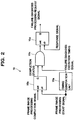
- FIG. 2 illustrates an exemplary configuration of the failure diagnosis control unit 10.
- the failure diagnosis control unit 10 includes a timing generation unit 10a, a set/reset type flip-flop 10b, an AND circuit 10c, and a set/reset type flip-flop 10d.
- the timing generation unit 10a can be configured to include a shift register, a counter, or a timer element and the like.
- FIG s. 3A and 3B are flowcharts illustrating the failure diagnosis control unit according to the first embodiment.
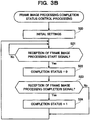
- FIG. 3A is a flowchart illustrating failure diagnosis execution control processing.
- FIG. 3B is a flowchart illustrating frame image processing completion status control processing. The failure diagnosis execution control processing illustrated in FIG. 3A and the frame image processing completion status control processing illustrated in FIG. 3B can be performed in parallel.
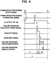
- FIG. 4 is a time chart illustrating the failure diagnosis processing.
- FIG. 5 is a time chart illustrating a case where the failure diagnosis processing is not performed.
- the imaging apparatus upon completing initial settings for the image processing apparatus 1 (step S10), the imaging apparatus (not illustrated) sequentially input image data to the image processing unit 11 at intervals of time T. For example, when the image capturing speed of the imaging apparatus is 30 frames per second, the image processing unit 11 acquires image data of one frame at intervals of approximately 33 msec. The image processing unit 11 sends the frame image processing start signal to the failure diagnosis control unit 10 at the timing to start image processing for one frame. If the failure diagnosis control unit 10 confirms reception of the frame image processing start signal (Yes in step S11), the failure diagnosis control unit 10 activates the counter of the timing generation unit 10a illustrated in FIG. 2 (step S12).
- step S20 initial settings (step S20) and acquisition and monitoring of the frame image processing start signal (step S21) are performed.
- Step S11 and step S21 are common processing. If the frame image processing start signal is acquired (Yes in step S21), the failure diagnosis control unit 10 sets a Q output (completion status) of the flip-flop 10b to low-level as illustrated in FIG. 4 (step S22).
- the timing generation unit 10a illustrated in FIG. 2 upon receiving the frame image processing start signal, activates the counter of the timing generation unit 10a (step S12). Then, the timing generation unit 10a compares a counter value with a setting value having been set beforehand and continues the counting operation until a predetermined time t1 elapses (step S13). The timing generation unit 10a, upon elapse of the predetermined time t1 (Yes in step S13), deactivates and initializes the counter and generates a failure diagnosis execution timing signal (step S14).
- the predetermined time t1 is set beforehand as a time obtainable by subtracting a value equal to or longer than the time required for the failure diagnosis processing from the time of a frame image processing start period.
- the predetermined time t1 is determined to be equal or less than a value obtainable by subtracting response time t2 required for the failure diagnosis processing unit 12 to return a response signal and time t3 required for the failure diagnosis processing from time T of the frame image processing start period.
- the image processing unit 11 upon completion of the image processing for one frame, sends the frame image processing completion signal to the failure diagnosis control unit 10.
- the failure diagnosis control unit 10 if the frame image processing completion signal is received (Yes in step S23), sets the Q output (completion status) of the flip-flop 10b to high-level, as illustrated in FIG. 4 (step S24).
- the duration in which the Q output of the flip-flop 10b remains at low-level is equal to the duration in which the image processing unit 11 is performing the image processing for one frame.
- the failure diagnosis control unit 10 determines whether the frame image processing completion signal has been received prior to the generation of the failure diagnosis execution timing signal by the timing generation unit 10a (step S15). If the frame image processing completion signal has been received prior to the generation of the failure diagnosis execution timing signal by the timing generation unit 10a (Yes in step S15), the Q output (completion status) of the flip-flop 10b turns into high-level before the failure diagnosis execution timing signal output from the timing generation unit 10a illustrated in FIG. 2 turns into high-level, as illustrated in FIG. 4 . Accordingly, as output of the AND circuit 10c, a signal having the same waveform as the failure diagnosis execution timing signal is output. Using this signal as a trigger, the flip-flop 10d outputs the failure diagnosis processing request signal.
- the failure diagnosis processing unit 12 upon receiving the failure diagnosis processing request signal, returns a response signal to the failure diagnosis control unit 10.
- the response signal resets the flip-flop 10d.
- the duration in which the failure diagnosis processing request signal (i.e., the Q output of the flip-flop 10d) remains at high-level is the response time t2 of the failure diagnosis processing unit 12.
- the failure diagnosis processing unit 12 diagnoses a failure of the image processing unit 11 (step S16). More specifically, the failure diagnosis processing unit 12 transmits scan test data to the image processing unit 11. The image processing unit 11 performs a scan test with the received scan test data. The failure diagnosis processing unit 12 receives a scan test result from the image processing unit 11. Then, the failure diagnosis processing unit 12 compares the scan test result with the expected value. The failure diagnosis processing unit 12, if the scan test result coincides with the expected value, determines that the image processing unit 11 has no failure. Further, the failure diagnosis processing unit 12, if the scan test result does not coincide with the expected value, determines that the image processing unit 11 has failure, and sends the failure detection signal to the interrupt control unit 13.
- the failure diagnosis processing unit 12 does not perform the failure diagnosis processing (No in step S15).
- the failure diagnosis control unit 10 repeats for a subsequent frame the processing in step S11 to step S15 (branched to No) or step S16. Further, in the frame image processing completion status control processing, after terminating the processing in step S23 (branched to No) or step S24, the failure diagnosis control unit 10 repeats for the subsequent frame the processing in step S21 to step S23 (branched to No) or step S24.
- the failure diagnosis control unit 10 controls the failure diagnosis processing unit 12 in such a way as to perform failure diagnosis after completing image processing for the corresponding frame.
- the failure diagnosis control unit 10 controls the failure diagnosis processing unit 12 in such a way as not to perform failure diagnosis after completing image processing for the corresponding frame, thereby preventing interruption of the failure diagnosis caused by lack of processing time.
- the failure diagnosis result obtained during the processing is never discarded, it is feasible to prevent any useless processing and contribute to saving of electric power consumption.
- failure diagnosis control unit 10 can be configured to be able to avoid halfway discard during the failure diagnosis with a small-scale circuit configuration illustrated in FIG. 2 , it is feasible to downsize the apparatus and realize electric power saving.
- FIG. 2 merely shows one possible configuration of the failure diagnosis control unit 10.
- the failure diagnosis control unit 10 is not limited to the above configuration.
- a circuit configuration illustrated in FIG. 7 can be employed to realize similar functions.
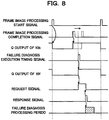
- FIG. 8 illustrates an exemplary operation of the failure diagnosis control unit 10 according to the modified example 1. As illustrated in FIG. 8 , the Q output of the flip-flop 10b turns into low-level at the timing when the frame image processing start signal turns into high-level. Further, the Q output of the flip-flop 10b turns into high-level at the timing when the frame image processing completion signal turns into high-level.
- the Q output of the flip-flop 10b When the Q output of the flip-flop 10b remains at high-level when the failure diagnosis execution timing signal is output from the timing generation unit 10a, a high-level signal is generated from a Q output of a flip-flop 10f. Further, when the Q output of the flip-flop 10b remains at low-level when the failure diagnosis execution timing signal is output from the timing generation unit 10a, a low-level signal is generated from the Q output of the flip-flop 10f. More specifically, in a case where the image processing by the image processing unit 11 is greatly delayed more than a predetermined time, the Q output of the flip-flop 10b remains at low-level at the timing to output the failure diagnosis execution timing signal and therefore the low-level signal is generated from the Q output of the flip-flop 10f.
- the failure diagnosis processing request signal is not output because the flip-flop 10d is not set, and accordingly the failure diagnosis processing is not executed.
- the flip-flop 10f resets beforehand the frame image processing start signal.
- the first embodiment and the modified example 1 employ a logic circuit to realize the failure diagnosis control unit 10.
- software processing may be employed to realize the functions of the failure diagnosis control unit 10.
- it can be realized by monitoring, with the software, the order of reception between the frame image processing completion signal output from the image processing unit 11 and the failure diagnosis execution timing signal output from the timing generation unit 10a, illustrated in FIG. 6 .
- a monitoring flag for monitoring the state of image processing can be provided.
- the frame image processing start signal sets the monitoring flag to 1, and the frame image processing completion signal resets the monitoring flag to 0.
- the CPU can be configured to read the monitoring flag at the reception timing of the failure diagnosis execution timing signal, and can be configured to perform the failure diagnosis processing if the monitoring flag is 0 and skip the failure diagnosis processing if the monitoring flag is 1.
- Using the software processing as mentioned above can realize functions similar to those realized by the hardware.
- the example of the failure diagnosis control processing described with reference to FIG s. 3A and 3B in the first embodiment is characterized by processing, in parallel, the failure diagnosis execution control processing and the frame image processing completion status control processing.
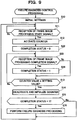
- an example of the failure diagnosis control processing characterized by performing, in series, the failure diagnosis execution control processing and the frame image processing completion status control processing will be described with reference to FIG. 9 .
- the failure diagnosis control unit 10 if the failure diagnosis control unit 10 receives the frame image processing start signal from the image processing unit 11 (Yes in step S11), the failure diagnosis control unit 10 activates the counter in the failure diagnosis control unit 10 (step S12) and clears the completion status in the failure diagnosis control unit 10 (step S22). If the frame image processing completion signal is received from the image processing unit 11 (Yes in step 23) before the counter value reaches the setting value (No in step S13), the failure diagnosis control unit 10 sets the completion status (step S24). If the frame image processing completion signal is not received (No in step S23), the failure diagnosis control unit 10 does not set the completion status.
- the failure diagnosis control unit 10 deactivates and initializes the counter (step S14). Subsequently, the failure diagnosis control unit 10 confirms whether the completion status is set (step S15). The failure diagnosis control unit 10, if the completion status is not set in step S15 (No in step S15), does not output the failure diagnosis processing request signal. The failure diagnosis control unit 10, if the completion status is set (Yes in step S15), outputs the failure diagnosis processing request signal and performs the failure diagnosis processing (step S16). The failure diagnosis control unit 10, upon terminating the processing in step S15 (branched to No) or step S16, repeats for a subsequent frame the processing in step S11 to step S15 (branched to No) or step S16.
- the failure diagnosis control unit 10 if the frame image processing start signal is received from the image processing unit 11 (Yes in step S11), activates the counter in the failure diagnosis control unit 10 (step S12).
- the failure diagnosis control unit 10 if the frame image processing completion signal is received from the image processing unit 11 (Yes in step 23) before the counter reaches the setting value (No in step S13), outputs the failure diagnosis processing request signal and performs the failure diagnosis (step S16).
- the failure diagnosis control unit 10 if the counter reaches the setting value or more in a state where the frame image processing completion signal is not received (Yes in step S13), does not output the failure diagnosis processing request signal.
- the failure diagnosis control unit 10 in response to the counter value reaching the setting value (Yes in step S13), or after outputting the failure diagnosis processing request signal, deactivates and initializes the counter (step S17).
- the failure diagnosis control unit 10 upon terminating the processing in step S17, repeats for a subsequent frame the processing in step S11 to step S17.
- the image processing unit 11, the failure diagnosis processing unit 12, and the system control unit 14 illustrated in FIG. 1 are respectively configured to include the DSP or the CPU.
- the hardware configuration is not limited to the above-mentioned examples.
- a plurality of CPUs or a single CPU may be used to perform all of the required processing.
- the failure diagnosis processing unit 12 is configured to use the scan test pattern and the expected value to perform the failure diagnosis.
- the contents of the failure diagnosis are not limited to the examples described above.
- the image processing unit 11 may be configured to execute some processing within a predetermined time and perform failure diagnosis based on the execution result.
- the ways combining the logic circuits is various.
- the above-mentioned configuration may be replaced by a negative logic circuit or a combination of positive and negative logic circuits.
- the AND circuit 10c illustrated in FIG. 2 may be replaced by a NAND circuit, an OR circuit, or a NOR circuit.
- the logic circuit can be configured without using any flip-flop.
- the positive logic means to constitute a logic circuit by expressing true (e.g., a function exerting state) as 1 (high-level) and false as 0 (low-level).
Landscapes
- Engineering & Computer Science (AREA)
- Multimedia (AREA)
- Signal Processing (AREA)
- Health & Medical Sciences (AREA)
- Biomedical Technology (AREA)
- General Health & Medical Sciences (AREA)
- Facsimiles In General (AREA)
- Test And Diagnosis Of Digital Computers (AREA)
- Image Processing (AREA)
- Testing, Inspecting, Measuring Of Stereoscopic Televisions And Televisions (AREA)
Abstract
Description
- Embodiments described herein relate generally to an image processing apparatus and a failure diagnosis control method.
- There is a conventional image processing apparatus that can perform image processing on a captured image frame by frame and diagnose a failure of an image processing unit frame by frame. The image processing apparatus performs the failure diagnosis during an idle time for the image processing by the image processing unit after completion of the image processing for an arbitrary frame before starting image processing for a subsequent frame. The failure diagnosis of the image processing unit includes transmitting a scan test pattern to the image processing unit and comparing the scan test result obtained from the image processing unit with an expected value.
- The time required for image processing on image data of one frame is variable depending on congestion of a system bus. For example, when abnormal interrupt processing or the like arises, the timing when the image processing completes may be greatly delayed due to the congestion of the system bus. When the completion timing of the image processing is delayed, the failure diagnosis cannot be completed before the timing to start the image processing of the subsequent frame, and will be stopped. If the scan test is discarded when the failure diagnosis is not able to be completed, the failure diagnosis is useless and becomes a cause of power waste. As an alternative way, when the failure diagnosis processing is interrupted for the image processing of subsequent frame, it may be possible to continue the failure diagnosis processing after the image processing of the subsequent frame. However, in such a case, an appropriate circuit will be additionally required to save the uncompleted scan test result of each register of the image processing unit. In addition, another circuit will be required to return the uncompleted scan test result to each register of the image processing unit before continuing the failure diagnosis processing. As a result, a problem that the circuit scale becomes larger arises.
-
-
FIG. 1 illustrates an exemplary configuration of an image processing apparatus according to a first embodiment. -
FIG. 2 illustrates an exemplary configuration of a failure diagnosis control unit according to the first embodiment. -
FIG. 3A is a flowchart illustrating a failure diagnosis control unit according to the first embodiment. -
FIG. 3B is a flowchart illustrating the failure diagnosis control unit according to the first embodiment. -
FIG. 4 illustrates the failure diagnosis control unit according to the first embodiment. -
FIG. 5 illustrates various signals and operational states of the failure diagnosis control unit according to the first embodiment. -
FIG. 6 illustrates the failure diagnosis control unit according to the first embodiment. -
FIG. 7 illustrates an exemplary configuration of a failure diagnosis control unit according to a modified example 1. -
FIG. 8 illustrates the failure diagnosis control unit according to the modified example 1. -
FIG. 9 is a flowchart illustrating a failure diagnosis control unit according to a second embodiment. -
FIG. 10 is a flowchart illustrating a failure diagnosis control unit according to a third embodiment. - Certain embodiments provide an image processing apparatus including an image processing unit configured to perform image processing on continuously captured image data frame by frame, a failure diagnosis processing unit configured to diagnose a failure of the image processing unit frame by frame, and a failure diagnosis control unit configured to control whether to perform the failure diagnosis for an arbitrary frame.
- Hereinafter, image processing apparatuses according to preferred embodiments will be described in detail below with reference to attached drawings.
- An image processing apparatus according to the first embodiment is, for example, an in-vehicle camera or another apparatus configured to perform image processing, such as luminance correction, on continuously captured image data frame by frame, and has a function of diagnosing a failure of an image processing unit frame by frame. The purpose of diagnosing the failure of the image processing unit frame by frame is to confirm the reliability of image data subjected to image processing and to prevent erroneous image information from being used in a drive assist control.
- An image processing apparatus 1, as illustrated in
FIG. 1 , includes a failurediagnosis control unit 10, animage processing unit 11, a failurediagnosis processing unit 12, aninterrupt control unit 13, asystem control unit 14, and astorage unit 15. Theimage processing unit 11, the failurediagnosis processing unit 12, theinterrupt control unit 13, thesystem control unit 14, and thestorage unit 15 are connected with each other via asystem bus 16. - The
storage unit 15 includes a random access memory (RAM), a read only memory (ROM), and a semiconductor memory and the like. Thestorage unit 15 stores image data processed by theimage processing unit 11, scan test data to be used by the failurediagnosis processing unit 12, and an expected value thereof. - The
image processing unit 11 includes a digital signal processing unit (DSP) and the like. Theimage processing unit 11, for example, performs image processing according to parameters having been set by thesystem control unit 14. Theimage processing unit 11 receives image data frame by frame from an imaging apparatus (not illustrated) and performs image processing. Although the contents of the image processing are not limited, theimage processing unit 11 may perform image processing, such as, color space conversion processing for conversion from RGB to YUV, luminance correction processing suitable for image recognition including amplifying or attenuating the luminance, edge emphasis processing, and zooming processing for changing the size of an object. Theimage processing unit 11 stores the image data subjected to the image processing, via thesystem bus 16, in thestorage unit 15. - Further, the
image processing unit 11, at the timing to start image processing for one frame, sends a frame image processing start signal (image processing start information) to the failurediagnosis control unit 10. Further, theimage processing unit 11, upon completion of the image processing for one frame, sends a frame image processing completion signal to the failurediagnosis control unit 10. - The failure
diagnosis processing unit 12 includes a DSP and the like. The failurediagnosis processing unit 12, under the control of the failurediagnosis control unit 10, performs processing for diagnosing a failure of theimage processing unit 11 frame by frame in a dormant period during which theimage processing unit 11 is not performing the image processing. More specifically, the failurediagnosis processing unit 12 sends scan test data to theimage processing unit 11, and acquires a scan test result from theimage processing unit 11. The value of the scan test result is already known when the scan test data has been normally subjected to theimage processing unit 11. The failurediagnosis processing unit 12 or thestorage unit 15 has beforehand an expected value corresponding to the scan test data. The failurediagnosis processing unit 12 compares the scan test result of theimage processing unit 11 with the expected value. The failurediagnosis processing unit 12 determines that theimage processing unit 11 is operating normally if the scan test result coincides with the expected value. And the failurediagnosis processing unit 12 determines that theimage processing unit 11 has failure if they do not coincide with each other. - The failure
diagnosis processing unit 12 performs the failure diagnosis processing only when a failure diagnosis processing request signal is received from the failurediagnosis control unit 10. The failurediagnosis processing unit 12, in response to the diagnosis processing request signal received from the failurediagnosis control unit 10, returns a response signal to the failurediagnosis control unit 10. In addition, the failurediagnosis processing unit 12 sends a failure detection signal to theinterrupt control unit 13 when the diagnosis result indicates that theimage processing unit 11 has failure. - The
interrupt control unit 13 sets respective cause registers based on a later-described image processing start signal and a failure diagnosis start signal for a related frame received from the failurediagnosis control unit 10 and the failure detection signal received from the failurediagnosis processing unit 12. Theinterrupt control unit 13 notifies thesystem control unit 14 of the setting of the cause registers by assertion of an interrupt signal. When thesystem control unit 14 confirms these causes via thesystem bus 16 and clears the cause registers, the interrupt signal is deasserted. Theinterrupt control unit 13 can be configured to include an OR logic circuit to which outputs from a plurality of cause registers are supplied. - The
system control unit 14 includes a central processing unit (CPU) and the like, and controls various operations to be performed by the image processing apparatus 1. Thesystem control unit 14, for example, when theinterrupt control unit 13 has confirmed the cause of a failure interrupt, or when the failure diagnosis start signal has not been confirmed before starting image processing for a subsequent frame, controls each apparatus in a vehicle in such a way as to prevent image data of a related frame from being used in recognition processing and the like. Further, thesystem control unit 14 may control each apparatus in the vehicle in such a way as to perform a display operation to inform the occurrence of a failure in theimage processing unit 11 or unsuccessful execution of the failure diagnosis. Further, thesystem control unit 14 may have a function of analyzing the cause of a failure with reference to information obtainable from various sensors in the apparatus. Then, thesystem control unit 14 may cause a display unit (not illustrated) to display the cause of the failure. - The failure
diagnosis control unit 10 controls whether to perform failure diagnosis after completing image processing for an arbitrary frame. More specifically, the failurediagnosis control unit 10 determines whether the failure diagnosis processing to be performed after the image processing for an arbitrary frame can be completed before starting image processing for a subsequent frame. Then, the failurediagnosis control unit 10, if it is determined that the failure diagnosis processing cannot be completed, controls the failurediagnosis processing unit 12 not to perform the failure diagnosis processing after completing the image processing for the arbitrary frame. In detail, if image processing completion information about an arbitrary frame is not received from theimage processing unit 11 until a pre-set time elapses since the start of the image processing for the arbitrary frame, the failurediagnosis control unit 10 controls the failurediagnosis processing unit 12 not to perform the failure diagnosis processing after completing the image processing for the arbitrary frame. -
FIG. 2 illustrates an exemplary configuration of the failurediagnosis control unit 10. As illustrated inFIG. 2 , the failurediagnosis control unit 10 includes atiming generation unit 10a, a set/reset type flip-flop 10b, an ANDcircuit 10c, and a set/reset type flip-flop 10d. Thetiming generation unit 10a can be configured to include a shift register, a counter, or a timer element and the like. - Next, operations of the failure
diagnosis control unit 10 will be described with reference to FIG s. 3 to 5. FIG s. 3A and 3B are flowcharts illustrating the failure diagnosis control unit according to the first embodiment.FIG. 3A is a flowchart illustrating failure diagnosis execution control processing.FIG. 3B is a flowchart illustrating frame image processing completion status control processing. The failure diagnosis execution control processing illustrated inFIG. 3A and the frame image processing completion status control processing illustrated inFIG. 3B can be performed in parallel.FIG. 4 is a time chart illustrating the failure diagnosis processing.FIG. 5 is a time chart illustrating a case where the failure diagnosis processing is not performed. - In the failure diagnosis execution control processing, upon completing initial settings for the image processing apparatus 1 (step S10), the imaging apparatus (not illustrated) sequentially input image data to the
image processing unit 11 at intervals of time T. For example, when the image capturing speed of the imaging apparatus is 30 frames per second, theimage processing unit 11 acquires image data of one frame at intervals of approximately 33 msec. Theimage processing unit 11 sends the frame image processing start signal to the failurediagnosis control unit 10 at the timing to start image processing for one frame. If the failurediagnosis control unit 10 confirms reception of the frame image processing start signal (Yes in step S11), the failurediagnosis control unit 10 activates the counter of thetiming generation unit 10a illustrated inFIG. 2 (step S12). - In parallel with the above-mentioned processing, in the frame image processing completion status control processing, initial settings (step S20) and acquisition and monitoring of the frame image processing start signal (step S21) are performed. Step S11 and step S21 are common processing. If the frame image processing start signal is acquired (Yes in step S21), the failure
diagnosis control unit 10 sets a Q output (completion status) of the flip-flop 10b to low-level as illustrated inFIG. 4 (step S22). - In the failure diagnosis execution control processing, the
timing generation unit 10a illustrated inFIG. 2 , upon receiving the frame image processing start signal, activates the counter of thetiming generation unit 10a (step S12). Then, thetiming generation unit 10a compares a counter value with a setting value having been set beforehand and continues the counting operation until a predetermined time t1 elapses (step S13). Thetiming generation unit 10a, upon elapse of the predetermined time t1 (Yes in step S13), deactivates and initializes the counter and generates a failure diagnosis execution timing signal (step S14). The predetermined time t1 is set beforehand as a time obtainable by subtracting a value equal to or longer than the time required for the failure diagnosis processing from the time of a frame image processing start period. More specifically, as illustrated inFIG. 4 , the predetermined time t1 is determined to be equal or less than a value obtainable by subtracting response time t2 required for the failurediagnosis processing unit 12 to return a response signal and time t3 required for the failure diagnosis processing from time T of the frame image processing start period. - In parallel with the above-mentioned processing, in the frame image processing completion status control processing, the
image processing unit 11, upon completion of the image processing for one frame, sends the frame image processing completion signal to the failurediagnosis control unit 10. The failurediagnosis control unit 10, if the frame image processing completion signal is received (Yes in step S23), sets the Q output (completion status) of the flip-flop 10b to high-level, as illustrated inFIG. 4 (step S24). Theimage processing unit 11, upon completing the storage of all the image data subjected to the image processing into thestorage unit 15 via thesystem bus 16, outputs the frame image processing completion signal. Accordingly, in a case where thesystem bus 16 is congested due to some reason, the timing to output the frame image processing completion signal may be delayed. The duration in which the Q output of the flip-flop 10b remains at low-level is equal to the duration in which theimage processing unit 11 is performing the image processing for one frame. - Subsequently, the failure
diagnosis control unit 10, as part of the failure diagnosis execution control processing, determines whether the frame image processing completion signal has been received prior to the generation of the failure diagnosis execution timing signal by thetiming generation unit 10a (step S15). If the frame image processing completion signal has been received prior to the generation of the failure diagnosis execution timing signal by thetiming generation unit 10a (Yes in step S15), the Q output (completion status) of the flip-flop 10b turns into high-level before the failure diagnosis execution timing signal output from thetiming generation unit 10a illustrated inFIG. 2 turns into high-level, as illustrated inFIG. 4 . Accordingly, as output of the ANDcircuit 10c, a signal having the same waveform as the failure diagnosis execution timing signal is output. Using this signal as a trigger, the flip-flop 10d outputs the failure diagnosis processing request signal. - The failure
diagnosis processing unit 12, upon receiving the failure diagnosis processing request signal, returns a response signal to the failurediagnosis control unit 10. The response signal resets the flip-flop 10d. The duration in which the failure diagnosis processing request signal (i.e., the Q output of the flip-flop 10d) remains at high-level is the response time t2 of the failurediagnosis processing unit 12. - In response to the failure diagnosis processing request signal, the failure
diagnosis processing unit 12 diagnoses a failure of the image processing unit 11 (step S16). More specifically, the failurediagnosis processing unit 12 transmits scan test data to theimage processing unit 11. Theimage processing unit 11 performs a scan test with the received scan test data. The failurediagnosis processing unit 12 receives a scan test result from theimage processing unit 11. Then, the failurediagnosis processing unit 12 compares the scan test result with the expected value. The failurediagnosis processing unit 12, if the scan test result coincides with the expected value, determines that theimage processing unit 11 has no failure. Further, the failurediagnosis processing unit 12, if the scan test result does not coincide with the expected value, determines that theimage processing unit 11 has failure, and sends the failure detection signal to the interruptcontrol unit 13. - On the other hand, if the frame image processing completion signal is received after the generation of the failure diagnosis execution timing signal by the
timing generation unit 10a (No in step S15), the Q output of the flip-flop 10b remains at low-level when the failure diagnosis execution timing signal output by thetiming generation unit 10a turns into high-level, as illustrated inFIG. 5 . Therefore, the signal of the Q output of the ANDcircuit 10c remains at low-level. Because of the absence of a trigger by the signal from the Q output of the ANDcircuit 10c, no failure diagnosis processing request signal is output from the flip-flop 10d. Accordingly, the failurediagnosis processing unit 12 does not perform the failure diagnosis processing (No in step S15). - In the failure diagnosis execution control processing, after terminating the processing in step S15 (branched to No) or step S16, the failure
diagnosis control unit 10 repeats for a subsequent frame the processing in step S11 to step S15 (branched to No) or step S16. Further, in the frame image processing completion status control processing, after terminating the processing in step S23 (branched to No) or step S24, the failurediagnosis control unit 10 repeats for the subsequent frame the processing in step S21 to step S23 (branched to No) or step S24. - As mentioned above, as illustrated in
FIG. 6 , if the frame image processing completion signal is received from theimage processing unit 11 before the predetermined time t1 elapses since reception of the frame image processing start signal for an arbitrary frame from theimage processing unit 11, the failurediagnosis control unit 10 controls the failurediagnosis processing unit 12 in such a way as to perform failure diagnosis after completing image processing for the corresponding frame. Further, if the frame image processing completion signal is not received from theimage processing unit 11 before the predetermined time t1 elapses since reception of the frame image processing start signal for an arbitrary frame from theimage processing unit 11, the failurediagnosis control unit 10 controls the failurediagnosis processing unit 12 in such a way as not to perform failure diagnosis after completing image processing for the corresponding frame, thereby preventing interruption of the failure diagnosis caused by lack of processing time. In addition, as the failure diagnosis result obtained during the processing is never discarded, it is feasible to prevent any useless processing and contribute to saving of electric power consumption. - Further, as the failure
diagnosis control unit 10 can be configured to be able to avoid halfway discard during the failure diagnosis with a small-scale circuit configuration illustrated inFIG. 2 , it is feasible to downsize the apparatus and realize electric power saving. - In the above description, the circuit illustrated in
FIG. 2 merely shows one possible configuration of the failurediagnosis control unit 10. The failurediagnosis control unit 10 is not limited to the above configuration. For example, a circuit configuration illustrated inFIG. 7 can be employed to realize similar functions.FIG. 8 illustrates an exemplary operation of the failurediagnosis control unit 10 according to the modified example 1. As illustrated inFIG. 8 , the Q output of the flip-flop 10b turns into low-level at the timing when the frame image processing start signal turns into high-level. Further, the Q output of the flip-flop 10b turns into high-level at the timing when the frame image processing completion signal turns into high-level. - When the Q output of the flip-
flop 10b remains at high-level when the failure diagnosis execution timing signal is output from thetiming generation unit 10a, a high-level signal is generated from a Q output of a flip-flop 10f. Further, when the Q output of the flip-flop 10b remains at low-level when the failure diagnosis execution timing signal is output from thetiming generation unit 10a, a low-level signal is generated from the Q output of the flip-flop 10f. More specifically, in a case where the image processing by theimage processing unit 11 is greatly delayed more than a predetermined time, the Q output of the flip-flop 10b remains at low-level at the timing to output the failure diagnosis execution timing signal and therefore the low-level signal is generated from the Q output of the flip-flop 10f. When the Q output of the flip-flop 10f remains at low-level, the failure diagnosis processing request signal is not output because the flip-flop 10d is not set, and accordingly the failure diagnosis processing is not executed. In order to perform the above-mentioned processing frame by frame, the flip-flop 10f resets beforehand the frame image processing start signal. - As described above, the first embodiment and the modified example 1 employ a logic circuit to realize the failure
diagnosis control unit 10. Alternatively, software processing may be employed to realize the functions of the failurediagnosis control unit 10. For example, it can be realized by monitoring, with the software, the order of reception between the frame image processing completion signal output from theimage processing unit 11 and the failure diagnosis execution timing signal output from thetiming generation unit 10a, illustrated inFIG. 6 . More specifically, a monitoring flag for monitoring the state of image processing can be provided. The frame image processing start signal sets the monitoring flag to 1, and the frame image processing completion signal resets the monitoring flag to 0. The CPU can be configured to read the monitoring flag at the reception timing of the failure diagnosis execution timing signal, and can be configured to perform the failure diagnosis processing if the monitoring flag is 0 and skip the failure diagnosis processing if the monitoring flag is 1. Using the software processing as mentioned above can realize functions similar to those realized by the hardware. - The example of the failure diagnosis control processing described with reference to FIG s. 3A and 3B in the first embodiment is characterized by processing, in parallel, the failure diagnosis execution control processing and the frame image processing completion status control processing. In the second embodiment, an example of the failure diagnosis control processing characterized by performing, in series, the failure diagnosis execution control processing and the frame image processing completion status control processing will be described with reference to
FIG. 9 . - In the example of the failure diagnosis control processing illustrated in
FIG. 9 , if the failurediagnosis control unit 10 receives the frame image processing start signal from the image processing unit 11 (Yes in step S11), the failurediagnosis control unit 10 activates the counter in the failure diagnosis control unit 10 (step S12) and clears the completion status in the failure diagnosis control unit 10 (step S22). If the frame image processing completion signal is received from the image processing unit 11 (Yes in step 23) before the counter value reaches the setting value (No in step S13), the failurediagnosis control unit 10 sets the completion status (step S24). If the frame image processing completion signal is not received (No in step S23), the failurediagnosis control unit 10 does not set the completion status. - When the counter in the failure
diagnosis control unit 10 reaches the setting value (Yes in step S13), the failurediagnosis control unit 10 deactivates and initializes the counter (step S14). Subsequently, the failurediagnosis control unit 10 confirms whether the completion status is set (step S15). The failurediagnosis control unit 10, if the completion status is not set in step S15 (No in step S15), does not output the failure diagnosis processing request signal. The failurediagnosis control unit 10, if the completion status is set (Yes in step S15), outputs the failure diagnosis processing request signal and performs the failure diagnosis processing (step S16). The failurediagnosis control unit 10, upon terminating the processing in step S15 (branched to No) or step S16, repeats for a subsequent frame the processing in step S11 to step S15 (branched to No) or step S16. - In the third embodiment, another example of the failure diagnosis control processing characterized by performing, in series, the failure diagnosis execution control processing and the frame image processing completion status control processing will be described with reference to
FIG. 10 . Explanations similar to those in the second embodiment will not be repeated. - In the example of the failure diagnosis control processing illustrated in
FIG. 10 , the failurediagnosis control unit 10, if the frame image processing start signal is received from the image processing unit 11 (Yes in step S11), activates the counter in the failure diagnosis control unit 10 (step S12). The failurediagnosis control unit 10, if the frame image processing completion signal is received from the image processing unit 11 (Yes in step 23) before the counter reaches the setting value (No in step S13), outputs the failure diagnosis processing request signal and performs the failure diagnosis (step S16). The failurediagnosis control unit 10, if the counter reaches the setting value or more in a state where the frame image processing completion signal is not received (Yes in step S13), does not output the failure diagnosis processing request signal. - The failure
diagnosis control unit 10, in response to the counter value reaching the setting value (Yes in step S13), or after outputting the failure diagnosis processing request signal, deactivates and initializes the counter (step S17). The failurediagnosis control unit 10, upon terminating the processing in step S17, repeats for a subsequent frame the processing in step S11 to step S17. - In the above description, the
image processing unit 11, the failurediagnosis processing unit 12, and thesystem control unit 14 illustrated inFIG. 1 are respectively configured to include the DSP or the CPU. However, the hardware configuration is not limited to the above-mentioned examples. For example, a plurality of CPUs or a single CPU may be used to perform all of the required processing. - Further, in the above description, the failure
diagnosis processing unit 12 is configured to use the scan test pattern and the expected value to perform the failure diagnosis. However, the contents of the failure diagnosis are not limited to the examples described above. Theimage processing unit 11 may be configured to execute some processing within a predetermined time and perform failure diagnosis based on the execution result. - Further, although the descriptions referring to FIG s. 2 and 7 are mainly based on the positive logic, the way of combining the logic circuits is various. For example, the above-mentioned configuration may be replaced by a negative logic circuit or a combination of positive and negative logic circuits. As a result, the AND
circuit 10c illustrated inFIG. 2 may be replaced by a NAND circuit, an OR circuit, or a NOR circuit. Further, the logic circuit can be configured without using any flip-flop. The positive logic means to constitute a logic circuit by expressing true (e.g., a function exerting state) as 1 (high-level) and false as 0 (low-level). - While certain embodiments have been described, these embodiments have been presented by way of example only, and are not intended to limit the scope of the inventions. Indeed, the novel embodiments described herein may be embodied in a variety of other forms; furthermore, various omissions, substitutions and changes in the form of the embodiments described herein may be made without departing from the spirit of the inventions. The accompanying claims and their equivalents are intended to cover such forms or modifications as would fall within the scope and sprit of the inventions.
Claims (6)
- An image processing apparatus(1), comprising:an image processing unit(11) configured to perform image processing on continuously captured image data frame by frame;a failure diagnosis processing unit(12) configured to diagnose a failure of the image processing unit(11); anda failure diagnosis control unit(10) configured to control whether to perform failure diagnosis at an arbitrary frame.
- The image processing apparatus(1) according to claim 1, wherein the failure diagnosis processing unit(12) transmits a scan test pattern to the image processing unit(11) and compares a scan test result of the image processing unit(11) with an expected value so as to diagnose a failure of the image processing unit(11), the failure diagnosis control unit(10) determines whether failure diagnosis processing to be performed frame by frame can be completed before starting image processing for a subsequent frame, and if it is determined that the failure diagnosis processing cannot be completed for the related frame before starting image processing for the subsequent frame, the failure diagnosis processing unit(12) is controlled so as not to perform the failure diagnosis processing in the related frame.
- The image processing apparatus(1) according to claim 1 or 2, wherein if image processing completion information about an arbitrary frame is not received from the image processing unit(11) until a pre-set time elapses after an image processing start information about the arbitrary frame is received from the image processing unit(11), the failure diagnosis control unit(10) controls the failure diagnosis processing unit(12) so as not to perform the failure diagnosis processing of the arbitrary frame.
- The image processing apparatus(1) according to any one of claims 1 to 3, wherein the failure diagnosis control unit(10) includes a timing generation unit(10a) configured to measure the pre-set time after the image processing start information about the arbitrary frame is received, and controls the failure diagnosis processing unit(12) so as not to perform the failure diagnosis processing at the arbitrary frame if the image processing completion information about the arbitrary frame is not received before the timing generation unit(10a) completes the measurement of the pre-set time.
- A failure diagnosis control method for an image processing apparatus(1) that includes an image processing unit(11) configured to perform image processing on continuously captured image data frame by frame, diagnoses a failure of the image processing unit(11) through a scan test in a duration in which the image processing unit(11) is not performing image processing for each frame, and controls whether to perform failure diagnosis at an arbitrary frame, the failure diagnosis control method comprising:determining whether failure diagnosis processing for the arbitrary frame can be completed before starting image processing for a subsequent frame; andcontrolling whether to perform the failure diagnosis processing for the arbitrary frame based on a determination result.
- The failure diagnosis control method according to claim 5, wherein the determining includes
starting a measurement of a pre-set time in response to reception of image processing start information about the arbitrary frame as a trigger, and
determining whether image processing completion information about the arbitrary frame has been received before completing the measurement of the pre-set time in the measurement,
wherein, in the determining, if the image processing completion information about the arbitrary frame has not been received before completing the measurement of the pre-set time, it is determined that the failure diagnosis processing at the arbitrary frame cannot be completed before starting the image processing for the subsequent frame, and
the controlling performs a control so as not to perform the failure diagnosis processing for the arbitrary frame, if it is determined that the failure diagnosis processing cannot be completed in the determining.
Applications Claiming Priority (1)
| Application Number | Priority Date | Filing Date | Title |
|---|---|---|---|
| JP2017174039A JP2019049884A (en) | 2017-09-11 | 2017-09-11 | Image processing apparatus and fault diagnosis control method |
Publications (1)
| Publication Number | Publication Date |
|---|---|
| EP3454555A1 true EP3454555A1 (en) | 2019-03-13 |
Family
ID=61580914
Family Applications (1)
| Application Number | Title | Priority Date | Filing Date |
|---|---|---|---|
| EP18157580.4A Withdrawn EP3454555A1 (en) | 2017-09-11 | 2018-02-20 | Image processing apparatus and failure diagnosis control method |
Country Status (4)
| Country | Link |
|---|---|
| US (2) | US10694176B2 (en) |
| EP (1) | EP3454555A1 (en) |
| JP (1) | JP2019049884A (en) |
| CN (1) | CN109495663A (en) |
Families Citing this family (5)
| Publication number | Priority date | Publication date | Assignee | Title |
|---|---|---|---|---|
| JP6771443B2 (en) * | 2017-09-21 | 2020-10-21 | 株式会社東芝 | Arithmetic processing unit and its method |
| JP7310138B2 (en) * | 2018-12-28 | 2023-07-19 | 株式会社リコー | IMAGE PROCESSING DEVICE, FAILURE DETECTION METHOD FOR IMAGE PROCESSING DEVICE, AND PROGRAM |
| JP7218216B2 (en) | 2019-03-08 | 2023-02-06 | 株式会社東芝 | Image processing device and detection method |
| CN112950951B (en) * | 2021-01-29 | 2023-05-02 | 浙江大华技术股份有限公司 | Intelligent information display method, electronic device and storage medium |
| CN112995656B (en) * | 2021-03-04 | 2024-05-17 | 黑芝麻智能科技(上海)有限公司 | Abnormality detection method and system for image processing circuit |
Citations (3)
| Publication number | Priority date | Publication date | Assignee | Title |
|---|---|---|---|---|
| JP2007022360A (en) * | 2005-07-19 | 2007-02-01 | Denso Corp | Vehicle security system |
| EP2879381A1 (en) * | 2012-07-26 | 2015-06-03 | Kyocera Corporation | Image monitoring device, mobile body, program, and failure determination method |
| WO2016117401A1 (en) * | 2015-01-20 | 2016-07-28 | 日立オートモティブシステムズ株式会社 | On-vehicle camera device |
Family Cites Families (20)
| Publication number | Priority date | Publication date | Assignee | Title |
|---|---|---|---|---|
| JPS5823207A (en) | 1981-07-31 | 1983-02-10 | Central Res Inst Of Electric Power Ind | Thermoelectric power plant equipped with stored steam power generation system |
| US5778008A (en) | 1995-05-10 | 1998-07-07 | Hitachi Denshi Kabushiki Kaisha | Fault diagnosis method of television camera apparatus |
| JPH096943A (en) | 1995-06-19 | 1997-01-10 | Hitachi Denshi Ltd | Image processing device failure diagnosis method |
| US9053222B2 (en) * | 2002-05-17 | 2015-06-09 | Lawrence A. Lynn | Patient safety processor |
| JP2005346674A (en) * | 2004-06-07 | 2005-12-15 | Ministry Of National Defense Chung Shan Inst Of Science & Technology | Systems, circuits, and methods for parallel processing of real-time signals using open structures |
| JP2007052669A (en) * | 2005-08-18 | 2007-03-01 | Konica Minolta Business Technologies Inc | Fault location diagnosis system, fault location identification method and apparatus to be diagnosed |
| JP2007274504A (en) * | 2006-03-31 | 2007-10-18 | Eastman Kodak Co | Digital camera |
| JP4255485B2 (en) * | 2006-08-11 | 2009-04-15 | シャープ株式会社 | Image processing apparatus abnormality detection method and image processing method |
| JP4752755B2 (en) | 2006-12-20 | 2011-08-17 | 富士ゼロックス株式会社 | Failure diagnosis device, failure diagnosis system, and failure diagnosis program |
| JP4433030B2 (en) * | 2007-10-01 | 2010-03-17 | ブラザー工業株式会社 | Image processing apparatus and control program for image processing apparatus |
| JP2010056964A (en) * | 2008-08-28 | 2010-03-11 | Canon Inc | Receiving apparatus and control method thereof, program, and recording medium |
| JP2011124986A (en) * | 2009-11-12 | 2011-06-23 | Sharp Corp | Image processing apparatus and image processing system |
| JP2011191511A (en) * | 2010-03-15 | 2011-09-29 | Sharp Corp | Image forming apparatus |
| JP2011211628A (en) * | 2010-03-30 | 2011-10-20 | Sony Corp | Image processing device and method, and program |
| JP6160242B2 (en) | 2013-05-27 | 2017-07-12 | 富士ゼロックス株式会社 | Fault diagnosis apparatus, image forming apparatus, and fault diagnosis system |
| JP6458579B2 (en) | 2014-10-27 | 2019-01-30 | 株式会社デンソー | Image processing device |
| US9852502B2 (en) | 2014-10-27 | 2017-12-26 | Denso Corporation | Image processing apparatus |
| JP6491507B2 (en) * | 2015-03-20 | 2019-03-27 | ルネサスエレクトロニクス株式会社 | Semiconductor device, electronic device and self-diagnosis method of semiconductor device |
| JP6540807B2 (en) * | 2015-07-24 | 2019-07-10 | コニカミノルタ株式会社 | Shooting console |
| US10748277B2 (en) * | 2016-09-09 | 2020-08-18 | Siemens Healthcare Gmbh | Tissue characterization based on machine learning in medical imaging |
-
2017
- 2017-09-11 JP JP2017174039A patent/JP2019049884A/en active Pending
-
2018
- 2018-01-29 CN CN201810082725.8A patent/CN109495663A/en active Pending
- 2018-02-20 EP EP18157580.4A patent/EP3454555A1/en not_active Withdrawn
- 2018-02-21 US US15/901,515 patent/US10694176B2/en active Active
-
2020
- 2020-05-13 US US15/931,098 patent/US10911746B2/en active Active
Patent Citations (4)
| Publication number | Priority date | Publication date | Assignee | Title |
|---|---|---|---|---|
| JP2007022360A (en) * | 2005-07-19 | 2007-02-01 | Denso Corp | Vehicle security system |
| EP2879381A1 (en) * | 2012-07-26 | 2015-06-03 | Kyocera Corporation | Image monitoring device, mobile body, program, and failure determination method |
| WO2016117401A1 (en) * | 2015-01-20 | 2016-07-28 | 日立オートモティブシステムズ株式会社 | On-vehicle camera device |
| EP3249902A1 (en) * | 2015-01-20 | 2017-11-29 | Hitachi Automotive Systems, Ltd. | On-vehicle camera device |
Also Published As
| Publication number | Publication date |
|---|---|
| US20200275090A1 (en) | 2020-08-27 |
| JP2019049884A (en) | 2019-03-28 |
| US10911746B2 (en) | 2021-02-02 |
| US20190082172A1 (en) | 2019-03-14 |
| US10694176B2 (en) | 2020-06-23 |
| CN109495663A (en) | 2019-03-19 |
Similar Documents
| Publication | Publication Date | Title |
|---|---|---|
| US10911746B2 (en) | Image processing apparatus and failure diagnosis control method | |
| US10609296B1 (en) | Electronic device and automatic exposure convergence method | |
| US8351805B2 (en) | Power saving processing apparatus, image forming apparatus, and computer readable medium that are adaptable to abnormalities | |
| US9888175B2 (en) | Image capturing accessory, image capturing apparatus, control method thereof and storage medium storing communication control program | |
| US20170134637A1 (en) | Lighting device that is capable of connecting to electronic apparatus, and control method therefor | |
| US20160156845A1 (en) | Low-powered image processing device and method of driving image processing device with low power | |
| KR101340438B1 (en) | Data processing apparatus, method of controlling the same | |
| US10628374B2 (en) | Electronic apparatus, image forming apparatus, and control method and program therefor | |
| JP2006311771A (en) | Device for detecting voltage variation | |
| US9842480B2 (en) | Alarm processing circuit | |
| US8436915B2 (en) | Image processing apparatus | |
| JPWO2018163554A1 (en) | Image sensor and transmission system | |
| JP7218216B2 (en) | Image processing device and detection method | |
| US20100316256A1 (en) | Object detection apparatus and method thereof | |
| US10922781B1 (en) | System for processing images from multiple image sensors | |
| US20160070610A1 (en) | Semiconductor device | |
| US12567289B2 (en) | Vehicle control system and vehicle control device | |
| US11758266B2 (en) | Image system on chip, image capturing system including the same, and image capturing method | |
| JP2011134057A (en) | Data processing apparatus, processing part, control circuit and data processing method | |
| US20220094906A1 (en) | Semiconductor device | |
| JP2019106053A (en) | Semiconductor device | |
| CN121151679A (en) | An IoT battery camera and its wake-up method, device and medium | |
| JP4403991B2 (en) | Information code reader and control method of information code reader | |
| TW202516466A (en) | Image processing device and method having motion detection mechanism | |
| JP6398780B2 (en) | Electronic control device for internal combustion engine |
Legal Events
| Date | Code | Title | Description |
|---|---|---|---|
| PUAI | Public reference made under article 153(3) epc to a published international application that has entered the european phase |
Free format text: ORIGINAL CODE: 0009012 |
|
| STAA | Information on the status of an ep patent application or granted ep patent |
Free format text: STATUS: REQUEST FOR EXAMINATION WAS MADE |
|
| 17P | Request for examination filed |
Effective date: 20180220 |
|
| AK | Designated contracting states |
Kind code of ref document: A1 Designated state(s): AL AT BE BG CH CY CZ DE DK EE ES FI FR GB GR HR HU IE IS IT LI LT LU LV MC MK MT NL NO PL PT RO RS SE SI SK SM TR |
|
| AX | Request for extension of the european patent |
Extension state: BA ME |
|
| STAA | Information on the status of an ep patent application or granted ep patent |
Free format text: STATUS: EXAMINATION IS IN PROGRESS |
|
| 17Q | First examination report despatched |
Effective date: 20191216 |
|
| STAA | Information on the status of an ep patent application or granted ep patent |
Free format text: STATUS: THE APPLICATION HAS BEEN WITHDRAWN |
|
| 18W | Application withdrawn |
Effective date: 20201112 |