EP3454067B1 - Systeme und verfahren zur prädiktiven batterieprüfung - Google Patents
Systeme und verfahren zur prädiktiven batterieprüfung Download PDFInfo
- Publication number
- EP3454067B1 EP3454067B1 EP18193880.4A EP18193880A EP3454067B1 EP 3454067 B1 EP3454067 B1 EP 3454067B1 EP 18193880 A EP18193880 A EP 18193880A EP 3454067 B1 EP3454067 B1 EP 3454067B1
- Authority
- EP
- European Patent Office
- Prior art keywords
- battery
- data indicative
- life
- resistance
- discharge
- Prior art date
- Legal status (The legal status is an assumption and is not a legal conclusion. Google has not performed a legal analysis and makes no representation as to the accuracy of the status listed.)
- Active
Links
Images




Classifications
-
- G—PHYSICS
- G01—MEASURING; TESTING
- G01R—MEASURING ELECTRIC VARIABLES; MEASURING MAGNETIC VARIABLES
- G01R31/00—Arrangements for testing electric properties; Arrangements for locating electric faults; Arrangements for electrical testing characterised by what is being tested not provided for elsewhere
- G01R31/36—Arrangements for testing, measuring or monitoring the electrical condition of accumulators or electric batteries, e.g. capacity or state of charge [SoC]
- G01R31/392—Determining battery ageing or deterioration, e.g. state of health
-
- G—PHYSICS
- G01—MEASURING; TESTING
- G01R—MEASURING ELECTRIC VARIABLES; MEASURING MAGNETIC VARIABLES
- G01R31/00—Arrangements for testing electric properties; Arrangements for locating electric faults; Arrangements for electrical testing characterised by what is being tested not provided for elsewhere
- G01R31/36—Arrangements for testing, measuring or monitoring the electrical condition of accumulators or electric batteries, e.g. capacity or state of charge [SoC]
- G01R31/3644—Constructional arrangements
- G01R31/3646—Constructional arrangements for indicating electrical conditions or variables, e.g. visual or audible indicators
-
- G—PHYSICS
- G01—MEASURING; TESTING
- G01R—MEASURING ELECTRIC VARIABLES; MEASURING MAGNETIC VARIABLES
- G01R31/00—Arrangements for testing electric properties; Arrangements for locating electric faults; Arrangements for electrical testing characterised by what is being tested not provided for elsewhere
- G01R31/36—Arrangements for testing, measuring or monitoring the electrical condition of accumulators or electric batteries, e.g. capacity or state of charge [SoC]
- G01R31/3644—Constructional arrangements
- G01R31/3648—Constructional arrangements comprising digital calculation means, e.g. for performing an algorithm
-
- G—PHYSICS
- G01—MEASURING; TESTING
- G01R—MEASURING ELECTRIC VARIABLES; MEASURING MAGNETIC VARIABLES
- G01R31/00—Arrangements for testing electric properties; Arrangements for locating electric faults; Arrangements for electrical testing characterised by what is being tested not provided for elsewhere
- G01R31/36—Arrangements for testing, measuring or monitoring the electrical condition of accumulators or electric batteries, e.g. capacity or state of charge [SoC]
- G01R31/385—Arrangements for measuring battery or accumulator variables
-
- G—PHYSICS
- G01—MEASURING; TESTING
- G01R—MEASURING ELECTRIC VARIABLES; MEASURING MAGNETIC VARIABLES
- G01R31/00—Arrangements for testing electric properties; Arrangements for locating electric faults; Arrangements for electrical testing characterised by what is being tested not provided for elsewhere
- G01R31/36—Arrangements for testing, measuring or monitoring the electrical condition of accumulators or electric batteries, e.g. capacity or state of charge [SoC]
- G01R31/389—Measuring internal impedance, internal conductance or related variables
-
- H—ELECTRICITY
- H01—ELECTRIC ELEMENTS
- H01M—PROCESSES OR MEANS, e.g. BATTERIES, FOR THE DIRECT CONVERSION OF CHEMICAL ENERGY INTO ELECTRICAL ENERGY
- H01M10/00—Secondary cells; Manufacture thereof
- H01M10/42—Methods or arrangements for servicing or maintenance of secondary cells or secondary half-cells
- H01M10/44—Methods for charging or discharging
-
- H—ELECTRICITY
- H01—ELECTRIC ELEMENTS
- H01M—PROCESSES OR MEANS, e.g. BATTERIES, FOR THE DIRECT CONVERSION OF CHEMICAL ENERGY INTO ELECTRICAL ENERGY
- H01M10/00—Secondary cells; Manufacture thereof
- H01M10/42—Methods or arrangements for servicing or maintenance of secondary cells or secondary half-cells
- H01M10/48—Accumulators combined with arrangements for measuring, testing or indicating the condition of cells, e.g. the level or density of the electrolyte
-
- H—ELECTRICITY
- H01—ELECTRIC ELEMENTS
- H01M—PROCESSES OR MEANS, e.g. BATTERIES, FOR THE DIRECT CONVERSION OF CHEMICAL ENERGY INTO ELECTRICAL ENERGY
- H01M10/00—Secondary cells; Manufacture thereof
- H01M10/42—Methods or arrangements for servicing or maintenance of secondary cells or secondary half-cells
- H01M10/48—Accumulators combined with arrangements for measuring, testing or indicating the condition of cells, e.g. the level or density of the electrolyte
- H01M10/486—Accumulators combined with arrangements for measuring, testing or indicating the condition of cells, e.g. the level or density of the electrolyte for measuring temperature
-
- H—ELECTRICITY
- H02—GENERATION; CONVERSION OR DISTRIBUTION OF ELECTRIC POWER
- H02J—ELECTRIC POWER NETWORKS; CIRCUIT ARRANGEMENTS OR SYSTEMS FOR SUPPLYING OR DISTRIBUTING ELECTRIC POWER; SYSTEMS FOR STORING ELECTRIC ENERGY
- H02J11/00—Circuit arrangements for providing service supply to auxiliaries of stations in which electric power is generated, distributed or converted
-
- H—ELECTRICITY
- H01—ELECTRIC ELEMENTS
- H01M—PROCESSES OR MEANS, e.g. BATTERIES, FOR THE DIRECT CONVERSION OF CHEMICAL ENERGY INTO ELECTRICAL ENERGY
- H01M2220/00—Batteries for particular applications
- H01M2220/10—Batteries in stationary systems, e.g. emergency power source in plant
-
- Y—GENERAL TAGGING OF NEW TECHNOLOGICAL DEVELOPMENTS; GENERAL TAGGING OF CROSS-SECTIONAL TECHNOLOGIES SPANNING OVER SEVERAL SECTIONS OF THE IPC; TECHNICAL SUBJECTS COVERED BY FORMER USPC CROSS-REFERENCE ART COLLECTIONS [XRACs] AND DIGESTS
- Y02—TECHNOLOGIES OR APPLICATIONS FOR MITIGATION OR ADAPTATION AGAINST CLIMATE CHANGE
- Y02E—REDUCTION OF GREENHOUSE GAS [GHG] EMISSIONS, RELATED TO ENERGY GENERATION, TRANSMISSION OR DISTRIBUTION
- Y02E60/00—Enabling technologies; Technologies with a potential or indirect contribution to GHG emissions mitigation
- Y02E60/10—Energy storage using batteries
Definitions
- the present disclosure relates generally to determining a remaining lifetime of a battery used to power a pitch system of a wind turbine.
- Batteries can be used to provide power in a variety of different applications.
- a battery can lose the ability to provide sufficient voltage to power a load as the battery ages. For instance, as a battery approaches end of life, an output voltage provided to a load can drop quickly.
- the inability of the battery to provide a required output voltage to power a load in certain condition can pose many challenges. For instance, the inability of a battery to power a load in a pitch drive system of a wind turbine system can result in an inability to pitch a wind turbine blade on a wind turbine, potentially leading to damage to the wind turbine.
- WO 2016/174 233 A1 relates to wind turbine backup power supply monitoring involving calculating a characteristic of the backup power supply based on monitored voltage and current values.
- An aspect of the present disclosure is directed to a method for determining the remaining lifetime of a battery used to power a pitch system of a wind turbine.
- the method includes conducting test operations of the battery, wherein each test operation includes controlling, by one or more control devices, a discharge of the battery through a load.
- Each test operation includes obtaining, by the one or more control devices, data indicative of a discharge voltage and a discharge current of the battery during discharge through the load.
- Each test operation includes obtaining, by the one or more control devices, data indicative of a temperature associated with the battery during discharge through the load.
- Each test operation includes determining, by the one or more control devices, data indicative of remaining lifetime of the battery as a function of the discharge voltage, the discharge current, and the temperature.
- Each test operation includes performing, by the one or more control devices, at least one control action based at least in part on the data indicative of the remaining lifetime of the battery. The test operations are conducted more frequently as the battery approaches an end of life of the battery.
- the test system includes a resistive load.
- the test system includes a voltage sensor configured to measure a discharge voltage of the battery.
- the test system includes a current sensor configured to measure a discharge current of the battery.
- the test system includes a temperature sensor configured to measure a temperature associated with the battery.
- the test system includes a switching device configured to couple the resistive load to the battery.
- the test system includes a control device having one or more processors configured to execute computer-readable instructions stored in one or more memory devices to perform test operations of the battery. Each test operation includes controlling the switching device to couple the resistive load to the battery and discharge the battery through the resistive load.
- Each test operation includes obtaining data indicative of a discharge voltage of the battery during discharge through the resistive load from the voltage sensor.
- Each test operation includes obtaining data indicative of a discharge current of the battery during discharge through the resistive load from the current sensor.
- Each test operation includes obtaining data indicative of the temperature associated with the battery during discharge through the resistive load.
- Each test operation includes determining data indicative of remaining lifetime of the battery as a function of the discharge voltage, discharge current, and the temperature.
- Each test operation includes performing at least one control action, particularly providing a notification of a fault condition, based at least in part on the data indicative of remaining lifetime of the battery.
- the control device is configured to conduct the test operations more frequently as the battery approaches an end of life of the battery.
- An example aspect of the present disclosure is directed to a method for preventing damaging loads from occurring during an adverse grid event of a wind turbine.
- the method includes conducting a test operation of at least one battery used to power a pitch drive mechanism of a rotor blade of the wind turbine.
- the method includes determining data indicative of remaining lifetime of the battery as a result of the one or more test operations as a function of a discharge current and a discharge voltage of the battery during the test operation.
- the method includes determining a fault condition based at least in part on data indicative of remaining lifetime of the battery.
- the method includes taking a preventive action based at least in part on the fault condition.
- Example aspects of the present disclosure are directed to systems and methods for determining a remaining lifetime of a battery.
- a remaining lifetime of a battery refers to the time remaining before the battery can no longer provide an output voltage above a threshold under load after being fully charged.
- the remaining lifetime of the battery typically decreases after multiple charging and discharging cycles.
- the remaining lifetime of a battery can be determined by subjecting the battery to a test operation.
- the test operation can include coupling the battery to a resistive load (e.g., a large resistor) and monitoring a discharge current and a discharge voltage of the battery.
- a resistive load e.g., a large resistor
- the test operation can close a switching element (e.g., a relay) to couple a battery to a resistive load for a time interval, such as a 6 second time interval, 5 second time interval, 4 second time interval, or other suitable time interval.
- a control device associated with the battery can obtain data indicative of a discharge current and a discharge voltage of the battery from suitable voltage and current sensors.
- Data indicative of a temperature associated with the battery e.g., a temperature of the battery enclosure or cabinet
- a temperature associated with the battery can also be obtained at the end of the time interval.
- An internal resistance of the battery can be determined based on the discharge voltage and the discharge resistance. For instance, in some embodiments, data indicative of a constant no load voltage for the battery can be obtained (e.g., from data specified by the battery manufacturer or from battery testing). A difference between the no load voltage for the battery and the discharge voltage can be determined. The difference can be divided by the discharge current to determine an internal resistance for the battery.
- the internal resistances for a brand new battery e.g., beginning of life resistance
- worn out battery e.g., end of life resistance
- the beginning of life and end of life resistances can be derived experimentally or from data from the battery manufacturer and correlated as a function of battery temperature.
- data indicative of a beginning of life resistance and an end of life resistance can be obtained.
- data indicative of a remaining lifetime of a battery can be determined based on the determined internal resistance and the beginning of life resistance and end of life resistance. For instance, in some embodiments, the data indicative of a remaining lifetime of a battery can be expressed as a percentage of the difference between beginning of life resistance and the end of life resistance relative to a difference between the internal resistance and the end of life resistance.
- a controller associated with the battery can be configured to take a control action based on the determined remaining lifetime of the battery. For instance, in some embodiments, a notification of a fault condition can be provided when a remaining lifetime of the battery falls below a threshold. In some embodiments, the notification for the fault condition can be provided when an average remaining lifetime over several operating tests of the battery falls below the threshold.
- the notification can be associated with replacing the battery. For instance, in response to the notification, a technician or other user can replace the battery with a fresh battery or battery with sufficient lifetime remaining. In this way, negative events associated with powering systems with worn out batteries can be reduced.
- a wind turbine can include a tower, a generator, a gearbox, a nacelle, and a rotor including one or more rotor blades.
- the rotor blades capture kinetic energy from wind using known foil principles and transmit the kinetic energy through rotational energy to turn a shaft coupling the rotor blades to a gearbox, or if a gearbox is not used, directly to the generator.
- the generator then converts the mechanical energy to electrical energy that may be deployed to a utility grid.
- the direction of the wind which powers the wind turbine may change.
- the wind turbine may thus adjust the nacelle through, for example, a yaw adjustment about a longitudinal axis of the tower to maintain alignment with the wind direction.
- the wind turbine may adjust a pitch angle of one or more of the rotor blades via a pitch drive mechanism configured with a pitch bearing to change the angle of the blades with respect to the wind.
- a pitch drive mechanism can include pitch drive motor, a pitch drive gearbox, and a pitch drive pinion.
- the pitch drive motor can be coupled to the pitch drive gearbox so that the pitch drive motor imparts mechanical force to the pitch drive gearbox.
- the pitch drive gearbox may be coupled to the pitch drive pinion for rotation therewith.
- the pitch drive pinion may, in turn, be in rotational engagement with the pitch bearing coupled between the hub and a corresponding rotor blade such that rotation of the pitch drive pinion causes rotation of the pitch bearing.
- rotation of the pitch drive motor drives the pitch drive gearbox and the pitch drive pinion, thereby rotating the pitch bearing and the rotor blade about the pitch axis.
- the pitch drive motors can be driven by electrical power from the power grid. However, in some instances, such as during an adverse grid event, the pitch drive motors may be driven by one or more backup batteries. If pitching of the blades relies on such batteries (i.e. due to a grid loss), it is important to ensure that the batteries are capable of operating when needed. Over time, however, the motor batteries of the pitch drive mechanisms lose their capacity to store energy and eventually die. Thus, if such batteries die without notice, the rotor blade associated with the dead batteries may become stuck since there is no power available to pitch the blade. In such instances, loads may increase on the stuck rotor blade, thereby causing damage thereto.
- Determining control actions based on determined remaining lifetime of a battery can reduce the likelihood of such damage to a wind turbine.
- a battery used to drive a pitch drive mechanism for a wind turbine can be periodically subjected to a test operation according to example embodiments of the present disclosure.
- Data indicative of remaining lifetime of the battery can be determined during the test operation.
- a fault condition can be determined based at least in part on data indicative of the remaining lifetime of the battery.
- the battery can be replaced, for instance, in response to the fault condition.
- obtaining can include receiving, determining, calculating, accessing, reading or otherwise obtaining data.
- FIG. 1 illustrates a perspective view of one embodiment of a wind turbine 10 according to example aspects of the present disclosure.
- the wind turbine 10 includes a tower 12 extending from a support surface 14, a nacelle 16 mounted on the tower 12, and a rotor 18 coupled to the nacelle 16.
- the rotor 18 includes a rotatable hub 20 and at least one rotor blade 22 coupled to and extending outwardly from the hub 20.
- the rotor 18 includes three rotor blades 22.
- the rotor 18 may include more or less than three rotor blades 22.
- Each rotor blade 22 may be spaced about the hub 20 to facilitate rotating the rotor 18 to enable kinetic energy to be transferred from the wind into usable mechanical energy, and subsequently, electrical energy.
- the hub 20 may be rotatably coupled to an electric generator 24 ( FIG. 2 ) positioned within the nacelle 16 to permit electrical energy to be produced.
- a generator 24 may be disposed within the nacelle 16.
- the generator 24 may be coupled to the rotor 18 of the wind turbine 10 for generating electrical power from the rotational energy generated by the rotor 18.
- the rotor 18 may include a main shaft 40 coupled to the hub 20 for rotation therewith.
- the generator 24 may then be coupled to the main shaft 40 such that rotation of the main shaft 40 drives the generator 24.
- the generator 24 includes a generator shaft 42 rotatably coupled to the main shaft 40 through a gearbox 44.
- the generator shaft 42 may be rotatably coupled directly to the main shaft 40.
- the generator 24 may be directly rotatably coupled to the main shaft 40.
- the main shaft 40 may generally be supported within the nacelle 16 by a support frame or bedplate 46 positioned atop the wind turbine tower 12.
- the main shaft 40 may be supported by the bedplate 46 via a pair of pillow blocks 48 mounted to the bedplate 46.
- the wind turbine 10 may also include a turbine control system or a turbine controller 26 within the nacelle 16.
- the turbine controller 26 is disposed within a control cabinet 52 mounted to a portion of the nacelle 16.
- the turbine controller 26 may be disposed at any location on or in the wind turbine 10, at any location on the support surface 14 or generally at any other location.
- the turbine controller 26 may generally be configured to control the various operating modes (e.g., start-up or shut-down sequences) and/or components of the wind turbine 10.
- Each rotor blade 22 may also include a pitch adjustment mechanism 32 configured to rotate each rotor blade 22 about its pitch axis 34.
- each pitch adjustment mechanism 32 may include a pitch drive motor 33 (e.g., any suitable electric, hydraulic, or pneumatic motor), a pitch drive gearbox 35, and a pitch drive pinion 37.
- the pitch drive motor 33 may be coupled to the pitch drive gearbox 35 so that the pitch drive motor 33 imparts mechanical force to the pitch drive gearbox 35.
- the pitch drive gearbox 35 may be coupled to the pitch drive pinion 37 for rotation therewith.
- the pitch drive pinion 37 may, in turn, be in rotational engagement with a pitch bearing 54 coupled between the hub 20 and a corresponding rotor blade 22 such that rotation of the pitch drive pinion 37 causes rotation of the pitch bearing 54.
- rotation of the pitch drive motor 33 drives the pitch drive gearbox 35 and the pitch drive pinion 37, thereby rotating the pitch bearing 54 and the rotor blade 22 about the pitch axis 34.
- the wind turbine 10 may include one or more yaw drive mechanisms 38 communicatively coupled to the controller 26, with each yaw drive mechanism(s) 38 being configured to change the angle of the nacelle 16 relative to the wind (e.g., by engaging a yaw bearing 56 of the wind turbine 10).
- the turbine controller 26 may also be communicatively coupled to each pitch adjustment mechanism 32 of the wind turbine 10 (one of which is shown) through a separate or integral pitch controller 30 ( FIG. 1 ) for controlling and/or altering the pitch angle of the rotor blades 22 (i.e., an angle that determines a perspective of the rotor blades 22 with respect to the direction 28 of the wind).
- one or more sensors 57, 58, 59 may be provided on the wind turbine 10. More specifically, as shown, a blade sensor 57 may be configured with one or more of the rotor blades 22 to monitor the rotor blades 22. Further, as shown, a wind sensor 58 may be provided on the wind turbine 10. For example, the wind sensor 58 may be a wind vane, an anemometer, a LIDAR sensor, or another suitable sensor that measures wind speed and/or direction. In addition, a pitch sensor 59 may be configured with each of the pitch drive mechanism(s) 32, e.g. with one or more batteries of the pitch drive motors 33 thereof, which will be discussed in more detail below.
- the sensors 57, 58, 59 may further be in communication with the controller 26, and may provide related information to the controller 26.
- the pitch sensor(s) 59 may correspond to temperature sensors that send temperature signals to the controllers 26, 30 to indicate an actual temperature of the pitch batteries, which is described in more detail herein.
- Additional sensors can include voltage and current sensors used as part of a test system for conducting test operations of a battery to determine remaining lifetime of the battery according to example embodiments of the present disclosure.
- the term "monitor" and variations thereof indicates that the various sensors of the wind turbine 10 may be configured to provide a direct measurement of the parameters being monitored and/or an indirect measurement of such parameters.
- the sensors described herein may, for example, be used to generate signals relating to the parameter being monitored, which can then be utilized by the controller 26 to determine the condition.
- a controller is one example of a control device.
- Other control devices can include microcontrollers, microprocessors, processing devices, application specific integrated circuits, or other devices configured to provide any of the control functionality and/or one or more of the operations of any of the methods disclosed herein.
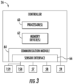
- the controller 26 may include one or more processor(s) 60 and associated memory device(s) 62 configured to perform a variety of computer-implemented functions (e.g., performing the methods, steps, calculations and the like and storing relevant data as disclosed herein). Additionally, the controller 26 may also include a communications module 64 to facilitate communications between the controller 26 and the various components of the wind turbine 10. For instance, the controller 26 can send control signals (e.g., via communications module 64) to switching elements (e.g., relays couple batteries to resistive load).
- control signals e.g., via communications module 64
- switching elements e.g., relays couple batteries to resistive load.
- the communications module 64 may include a sensor interface 66 (e.g., one or more analog-to-digital converters) to permit signals transmitted from one or more sensors 57, 58, 59 to be converted into signals that can be understood and processed by the processors 60.
- the sensors 57, 58, 59 may be communicatively coupled to the communications module 64 using any suitable means.
- the sensors 57, 58, 59 are coupled to the sensor interface 66 via a wired connection.
- the sensors 57, 58, 59 may be coupled to the sensor interface 66 via a wireless connection, such as by using any suitable wireless communications protocol known in the art.
- a voltage sensor 158 can be in communication with the controller 26.
- the voltage sensor 158 can be part of a test system for a battery for powering a pitch adjustment mechanism.
- the voltage sensor 158 can be configured to measure an output voltage (e.g., discharge voltage) of the battery when the battery is coupled to a test resistive load.
- a current sensor 159 can be in communication with the controller 26.
- the current sensor 159 can be part of a test system for a battery for powering a pitch adjustment mechanism.
- the current sensor 159 can be configured to measure an output current (e.g., discharge current) of the battery when the battery is coupled to a test resistive load.
- the term "processor” refers not only to integrated circuits referred to in the art as being included in a computer, but also refers to a controller, a microcontroller, a microcomputer, a programmable logic controller (PLC), an application specific integrated circuit, and other programmable circuits.
- the memory device(s) 62 may generally comprise memory element(s) including, but not limited to, computer readable medium (e.g., random access memory (RAM)), computer readable non-volatile medium (e.g., a flash memory), a floppy disk, a compact disc-read only memory (CD-ROM), a magneto-optical disk (MOD), a digital versatile disc (DVD) and/or other suitable memory elements.
- RAM random access memory
- CD-ROM compact disc-read only memory
- MOD magneto-optical disk
- DVD digital versatile disc
- Such memory device(s) 62 may generally be configured to store suitable computer-readable instructions that, when implemented by the processor(s) 60, configure the controller 26 to perform various functions including, but not limited to, transmitting suitable control signals to implement corrective action(s) in response to a distance signal exceeding a predetermined threshold as described herein, as well as various other suitable computer-implemented functions.
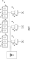
- the pitch system 70 may include a plurality of pitch drive mechanisms 32, i.e. one for each pitch axis 34. Further, as shown, each of the pitch drive mechanisms may be communicatively coupled to the power grid 45 as well as one or more backup batteries 72. More specifically, as shown, each pitch drive mechanism 32 may be associated with a plurality of backup batteries 72 that are stored in a battery cabinet 74. Thus, in certain embodiments, the battery cabinets 74 may be thermally isolated containers.
- the pitch drive motors 33 are driven by the power grid 45. However, in some instances, such as during an adverse grid event or grid loss, the pitch drive motors 33 may be driven by one or more backup batteries 72. If pitching of the rotor blades 22 relies on such batteries 72 (i.e. due to a grid loss), it is important to ensure that the batteries 72 are capable of operating when needed.
- the turbine controller 26 or pitch controller 30 is configured to implement a control strategy to estimate the consumed battery life of one or more of the batteries 72 of the pitch drive mechanisms 32 so as to reduce damaging loads from occurring during an adverse grid event of a wind turbine 10 or any other scenarios where battery power is used to pitch the rotor blades 22.
- FIG. 5 depicts an example test system 100 for conducting a test operation of a battery to determine remaining lifetime of a battery (e.g., batteries 72) according to example embodiments of the present disclosure.
- the test system 100 includes a switching element 110, such as one or more relays, transistors, or other switching elements that can be controlled to be in a conducting state or non-conducting state.
- the test system 100 includes a resistive load 120 (e.g., a test resistive load).
- a control device e.g., controller 26
- the length of the time interval can be, for instance, about 6 seconds, about 5 seconds, about 10 seconds, about 1 second, or any other suitable time interval.
- the battery 72 discharges through the resistive load 120.
- the test system 100 can include a voltage sensor 158 and a current sensor 159.
- the voltage sensor 158 can monitor an output voltage/discharge voltage (V L ) for the battery 72 during discharge of the battery 72 through the load 120.
- the current sensor 159 can monitor an output current/discharge current (I L ) of the battery 72 through the load 120.
- the test system can also include a sensor 59 ( FIG. 4 ) that measures a temperature associated with the battery 72.
- the sensor 59 can measure a temperature of a battery cabinet 74 enclosing the battery 72.
- a model can be used to estimate the internal temperature of the battery based on the measured cabinet temperature.
- the model can correlate internal temperature relative to measured cabinet temperature over time.
- the sensor 59 can measure a temperature associated with one or more battery chargers used to charge the battery.
- the control device e.g., controller 26
- the control device can be configured to determine a remaining lifetime for the battery 72 based on data indicative of the temperature associated with the battery, the discharge voltage V L and the discharge current I L .
- the controller 26 can execute computer-readable instructions stored in a memory to perform operations to determine a remaining lifetime for the battery 72.
- FIG. 6 depicts a flow diagram of an example method (200) (e.g., operations) for determining a lifetime remaining of a battery according to example embodiments of the present disclosure.
- the method (200) can be implemented, for instance, by controller 26 or other control device(s).
- FIG. 6 depicts steps performed in a particular order for purposes of illustration and discussion. Those of ordinary skill in the art, using the disclosures provided herein, will understand that various steps of any of the methods disclosed herein can be adapted, expanded, rearranged, performed simultaneously, and/or rearranged in various ways without deviating from the scope of the present disclosure.
- the method can include controlling a discharge of the battery through a load.
- the controller 26 can send a control signal to switching element 110 to couple the battery 72 to the resistive load 120.
- the method can include obtaining data indicative of a discharge voltage of the battery during discharge through the load.
- the controller 26 can obtain data from voltage sensor 158 indicative of discharge voltage V L .
- the method can include obtaining data indicative of a discharge current of the battery during discharge through the load.
- the controller 26 can obtain data from current sensor 159 indicative of discharge current I L .
- the method can include obtaining data indicative of a temperature associated with the battery, such as a temperature of the cabinet housing the battery and/or a temperature of one or more battery chargers used to charge the battery.
- the controller 26 can obtain data from temperature sensor 59 indicative of a temperature of battery cabinet 74 of the battery 72.
- the method can include determining data indicative of remaining lifetime of the battery.
- the controller 26 can execute logic (e.g., computer-readable instructions) to perform operations to determine remaining lifetime of the battery based at least in part on the data indicative of the discharge voltage V L , the data indicative of the discharge current I L , and the temperature associated with the battery 72.
- the data indicative of remaining lifetime can be associated with internal resistance of the battery.
- the internal resistance can be determined as function of at least the discharge voltage and the discharge current as discussed with reference to FIG. 7 below.
- the data indicative of estimated lifetime of the battery can include a ratio of a difference between the internal resistance and an end of life resistance associated with the battery to a difference between a beginning of life resistance and an end of life resistance associated with the battery.
- an end of life resistance of a battery refers to a resistance value at or near internal resistance of a battery at end of life (e.g., within 20% of the internal resistance of the battery at end of life).
- the end of life resistance can vary as a function of temperature associated with the battery.
- the end of life resistance can be determined from specification from the battery manufacturer or from test data from testing batteries of similar construction.
- a beginning of life resistance of a battery refers to a resistance value at or near internal resistance of a battery at beginning of life. (e.g., within 20% of the internal resistance of the battery at beginning of life).
- the beginning of life resistance can vary as a function of temperature associated with the battery.
- the beginning of life resistance can be determined from specification from the battery manufacturer or from test data from testing batteries of similar construction.
- FIG. 7 depicts a flow diagram of one example method (300) of performing operations to determine data indicative of remaining lifetime of the battery according to example embodiments of the present disclosure.
- the method (300) can be implemented, for instance, by controller 26 or other control device(s).
- FIG. 7 depicts steps performed in a particular order for purposes of illustration and discussion. Those of ordinary skill in the art, using the disclosures provided herein, will understand that various steps of any of the methods disclosed herein can be adapted, expanded, rearranged, performed simultaneously, and/or rearranged in various ways without deviating from the scope of the present disclosure.
- the method includes determining an internal resistance of the battery as a function of at least the discharge voltage and the discharge current.
- the internal resistance can be determined by determining a difference between a no load voltage of the battery and the discharge voltage of the battery. The difference can be divided by the discharge current.
- V NoLoad can be a constant that is obtained from manufacturer specifications or testing of batteries of similar construction.
- the method can include obtaining data indicative of beginning of life resistance and end of life resistance of the battery. As these values can be dependent on temperature, the beginning of life resistance and end of life resistance for the battery can be determined based at least in part on the data indicative of the temperature associated with the battery.
- the method can include determining a first difference between the internal resistance and the end of life resistance. For instance, the internal resistance can be subtracted from the end of life resistance (or vice versa) to determine the first difference.
- the method can include determining a second difference between the beginning of life resistance and the end of life resistance. For instance, the beginning of life resistance can be subtracted from the end of life resistance (or vice versa) to determine the second difference.
- the method can include determining a ratio of the first difference and the second difference. For instance, the first difference can be divided by the second difference.
- the ratio can be expressed as a percentage of lifetime remaining. For example, if the ratio is determined to be 0.20, the percentage of lifetime remaining can be 20%. As another example, if the ratio is determined to be 0.34, the percentage of lifetime remaining can be 34%.
- FIG. 8 depicts a graphical representation of determining a remaining lifetime of a battery according to example embodiments of the present disclosure.
- FIG. 8 plots measured temperature along the horizontal axis and internal resistance of the battery along the vertical axis.
- Curve 410 represents the beginning of life resistance as a function of temperature.
- Curve 420 represents the end of life resistance as a function of temperature.
- Curve 430 represents a threshold resistance as a function of temperature. Curve 430 can be used to determine when to take a control action based on the internal resistance. As shown in FIG. 8 , the calculated resistance can be used to determine a percent lifetime remaining.
- Area 440 represents the percent lifetime remaining of the battery.
- the threshold curve 430 can be compensated based on the charge of the battery, especially in cases where the batteries are not fully charged.
- the method can include performing at least one control action based at least in part on the data indicative of remaining lifetime of the battery.
- the controller 26 can implement at least one control action based at least in part on the data indicative of remaining lifetime of the battery.
- the method can include performing the control action.
- the test operation can be performed multiple times at regular or irregular time intervals to determine a plurality of estimates of remaining lifetime for the battery (e.g., a plurality of internal resistances for the battery). An average remaining lifetime for the battery can be determined.
- a control action can be performed when the average remaining lifetime falls below a threshold.
- the control action can include providing a notification of a fault condition associated with the battery.
- the controller 26 can send a notification using any suitable output device (e.g., display screen, visual indicator, audio speaker, or other suitable output device) indicative of a fault condition of the battery.
- the fault condition can be indicative of the battery nearing end of life.
- the notification can be associated with replacing the battery. For instance, in response to the notification, the battery can be replaced with a new battery or battery with more remaining lifetime.
- control action can include shutting down the wind turbine until the battery is replaced.
- the turbine can be shut down when the remaining lifetime of the battery is below a certain threshold. This threshold can be far enough away from the end of life threshold to avoid battery failure before the next retest.
- the method can be performed and/or modified based on data from multiple batteries.
- the data from a battery can be compared to data from a set of batteries, such as a set of batteries within the same axis, turbine, or age group. If, for example, several or all batteries in the set exhibit the same characteristic, such as being at a similar voltage below the end of life threshold, it can be determined that a condition such as temperature is causing the characteristic.
- the method can be modified. For instance, the voltage threshold can be adjusted or trained at varying temperatures to reflect deviation learned from field experience to better reflect the actual end of life threshold at each temperature.
- the frequency of the tests is determined based on data from the battery.
- the frequency of the tests is based upon the remaining lifetime of the battery.
- the frequency of the tests is increased as the battery approaches end of life.
- the controller 26 can be configured to test the battery infrequently near beginning of life and gradually more frequently as it approaches end of life. This can reduce unnecessary cycling of the batteries caused by testing while ensuring a battery does not reach end of life and fail between tests.
- past patterns of misses such as if the method was not effective in detecting a failing battery prior to failure, can be identified. These past patterns of misses can be used to modify the method. For instance, the past patterns of misses can be used to detect that the algorithm generally was not efficient at detecting failing batteries under a certain pattern of turbine or environmental conditions. The algorithm can then be adjusted or modified based on the past pattern of misses.
- an additional check can be used to help determine false positives.
- the battery can be flagged for recheck based on a recheck algorithm to avoid an early replacement based on a false positive.
- the battery data can be considered, such as by a human, and determined to be in a false positive condition, in which case steps such as a retest and/or ignoring the false positive can be taken.
- FIG. 9 depicts a flow diagram of an example method (500) for preventing damage to a wind turbine according to example embodiments of the present disclosure.
- the method (500) can be at least partially implemented, for instance, by controller 26 or other control device(s).
- the method (500) is used to ensure that a battery used to power a pitch system of a wind turbine does not fail during operation.
- FIG. 9 depicts steps performed in a particular order for purposes of illustration and discussion. Those of ordinary skill in the art, using the disclosures provided herein, will understand that various steps of any of the methods disclosed herein can be adapted, expanded, rearranged, performed simultaneously, and/or rearranged in various ways without deviating from the scope of the present disclosure.
- the method includes conducting a test operation of the battery, such as any of the test operations of the battery disclosed herein.
- the method includes determining data indicative of remaining lifetime of a battery according to any of the methods or operations for determining remaining lifetime disclosed herein.
- a fault condition can be determined based on the remaining lifetime of the battery. For instance, a fault condition can be determined when the remaining lifetime of the battery is below a threshold.
- the method can include replacing the battery in response to the fault condition. In this way, the method can increase the likelihood that a fresh battery will be available to power a pitch system of a wind turbine.
Landscapes
- Physics & Mathematics (AREA)
- General Physics & Mathematics (AREA)
- Engineering & Computer Science (AREA)
- Manufacturing & Machinery (AREA)
- Chemical & Material Sciences (AREA)
- Chemical Kinetics & Catalysis (AREA)
- Electrochemistry (AREA)
- General Chemical & Material Sciences (AREA)
- Power Engineering (AREA)
- Wind Motors (AREA)
- Secondary Cells (AREA)
Claims (15)
- Verfahren (200) zum Bestimmen der verbleibenden Lebensdauer einer Batterie (72), die zum Betreiben eines Pitch-Systems einer Windturbine verwendet wird, wobei das Verfahren (200) das Durchführen von Testvorgängen der Batterie umfasst, wobei jeder Testvorgang umfasst:Steuern (202), durch eine oder mehrere Steuervorrichtungen (26), einer Entladung der Batterie (72) durch eine Last (120);
Erhalten (204), durch die eine oder die mehreren Steuervorrichtungen (26), von Daten, die eine Entladespannung und (206) einen Entladestrom der Batterie (72) während der Entladung durch die Last (120) anzeigen;Erhalten (208), durch die eine oder die mehreren Steuervorrichtungen (26), von Daten, die eine mit der Batterie (72) verknüpfte Temperatur während der Entladung durch die Last (120) anzeigen;Bestimmen (210), durch die eine oder mehreren Steuervorrichtungen (26), von Daten, die die verbleibende Lebensdauer der Batterie (72) anzeigen, als eine Funktion der Entladespannung, des Entladestroms und der Temperatur; undDurchführen (212), durch die eine oder mehreren Steuervorrichtungen (26), mindestens einer Steueraktion, die zumindest teilweise auf den Daten basiert, die die verbleibende Lebensdauer der Batterie (72) anzeigen;wobei die Testvorgänge häufiger durchgeführt werden, wenn sich die Batterie dem Ende ihrer Lebensdauer nähert. - Verfahren (200) nach Anspruch 1, wobei die Daten, die die verbleibende Lebensdauer der Batterie (72) anzeigen, mit einem Innenwiderstand der Batterie (72) verknüpft sind, wobei der Innenwiderstand als eine Funktion von zumindest der Entladespannung und dem Entladestrom bestimmt wird.
- Verfahren (200) nach Anspruch 2, wobei die Daten, die die verbleibende Lebensdauer der Batterie (72) anzeigen, ein Verhältnis einer Differenz zwischen dem Innenwiderstand und einem Widerstand am Ende der Lebensdauer der Batterie zu einer Differenz zwischen einem Widerstand am Anfang der Lebensdauer und dem Widerstand am Ende der Lebensdauer der Batterie umfassen.
- Verfahren (200) nach Anspruch 3, wobei der Anfangswiderstand und der Endwiderstand zumindest teilweise auf der Grundlage von Daten bestimmt werden, die die Temperatur der Batterie (72) anzeigen.
- Verfahren (200) nach Anspruch 3 oder Anspruch 4, wobei (210) das Bestimmen, durch die eine oder die mehreren Steuervorrichtungen (26), von Daten, die die verbleibende Lebensdauer der Batterie (72) anzeigen, umfasst:Bestimmen (302), durch die eine oder die mehreren Steuervorrichtungen (26), des Innenwiderstands der Batterie (72) als eine Funktion von mindestens der Entladespannung und dem Entladestrom;Erhalten (304), durch die eine oder die mehreren Steuervorrichtungen (26), des Widerstands zu Beginn der Lebensdauer und des Widerstands am Ende der Lebensdauer für die Batterie (72); undBestimmen (306), durch die eine oder die mehreren Steuervorrichtungen (26), einer ersten Differenz zwischen dem Innenwiderstand und dem Widerstand am Ende der Lebensdauer;Bestimmen (308), durch die eine oder die mehreren Steuervorrichtungen (26), einer zweiten Differenz zwischen dem Widerstand zu Beginn der Lebensdauer und dem Widerstand am Ende der Lebensdauer; undBestimmen (310), durch die eine oder die mehreren Steuervorrichtungen (26), eines Verhältnisses der ersten Differenz zur zweiten Differenz; undBestimmen (312), durch die eine oder die mehreren Steuervorrichtungen, einer verbleibenden prozentualen Lebensdauer basierend auf dem Verhältnis.
- Verfahren (200) nach einem beliebigen vorhergehenden Anspruch, wobei die mindestens eine Steuerungsaktion das Bereitstellen einer Benachrichtigung über einen Fehlerzustand umfasst, die zumindest teilweise auf den Daten basiert, die die verbleibende Lebensdauer der Batterie (72) anzeigen.
- Verfahren (200) des Anspruchs 6, wobei die Benachrichtigung mit dem Austausch der Batterie (72) verknüpft ist.
- Verfahren (200) nach Anspruch 6 oder 7, wobei das Verfahren umfasst:Bestimmen einer durchschnittlichen prozentualen verbleibenden Lebensdauer für die Batterie (72) zumindest teilweise auf der Grundlage einer Vielzahl von Innenwiderständen, die für jedes einer Vielzahl von Zeitintervallen bestimmt werden; undBereitstellen der Benachrichtigung über einen Fehlerzustand zumindest teilweise auf der Grundlage der durchschnittlichen prozentualen Lebensdauer.
- Verfahren (200) nach einem der vorhergehenden Ansprüche, wobei die Batterie (72) in einem Batterieschrank (74) gelagert wird, wobei die mit der Batterie (72) verknüpfte Temperatur mit einer Schranktemperatur des Batterieschranks (74) korrespondiert.
- Verfahren (200) nach einem der vorhergehenden Ansprüche, wobei die Batterie (72) in einem Batterieschrank (74) gelagert wird, der eine oder mehrere Batterien und ein oder mehrere Batterieladegeräte enthält, wobei die mit der Batterie (72) verknüpfte Temperatur mit der Temperatur des einen oder der mehreren Batterieladegeräte korrespondiert.
- Testsystem (100), das zum Testen der verbleibenden Lebensdauer einer Batterie (72) konfiguriert ist, die zum Betreiben eines Pitch-Systems (32) in einer Windturbine (10) verwendet wird, wobei das Testsystem umfasst:eine ohmsche Last (120);einen Spannungssensor (158), der so konfiguriert ist, dass er eine Entladespannung der Batterie (72) misst;einen Stromsensor (159), der so konfiguriert ist, dass er einen Entladestrom der Batterie (72) misst;einen Temperatursensor (59), der so konfiguriert ist, dass er eine mit der Batterie (72) verknüpfte Temperatur misst;eine Schaltvorrichtung (110), die so konfiguriert ist, dass sie die ohmsche Last (120) mit der Batterie (72) koppelt; undeine Steuervorrichtung (26) mit einem oder mehreren Prozessoren (60), die so konfiguriert sind, dass sie computerlesbare Anweisungen ausführen, die in einer oder mehreren Speichervorrichtungen (62) gespeichert sind, um Testvorgänge der Batterie durchzuführen, wobei jeder Testvorgang umfasst:wobei die Steuervorrichtung (26) so konfiguriert ist, dass sie die Testvorgänge häufiger durchführt, wenn sich die Batterie dem Ende ihrer Lebensdauer nähert.Steuern der Schaltvorrichtung (110), um die ohmsche Last (120) mit der Batterie (72) zu koppeln und die Batterie (72) über die ohmsche Last (120) zu entladen;Erhalten von Daten, die eine Entladespannung der Batterie (72) während der Entladung durch die ohmsche Last (120) anzeigen, von dem Spannungssensor (158);Erhalten von Daten, die einen Entladestrom der Batterie (72) während der Entladung durch die ohmsche Last (120) anzeigen, von dem Stromsensor (159);Erhalten von Daten, die die Temperatur anzeigen, die mit der Batterie (72) während der Entladung durch die ohmsche Last (120) verknüpft ist; undBestimmen von Daten, die die verbleibende Lebensdauer der Batterie (72) als eine Funktion der Entladespannung, des Entladestroms und der Temperatur anzeigen; undDurchführen (212) mindestens einer Steueraktion, die zumindest teilweise auf den Daten basiert, die die verbleibende Lebensdauer der Batterie (72) anzeigen;
- System (100) nach Anspruch 11, wobei die Daten, die die verbleibende Lebensdauer der Batterie (72) anzeigen, mit einem Innenwiderstand der Batterie (72) verknüpft sind, wobei der Innenwiderstand als eine Funktion von mindestens der Entladespannung und dem Entladestrom bestimmt wird.
- System (100) nach Anspruch 12, wobei die Daten, die die verbleibende Lebensdauer der Batterie (72) anzeigen, ein Verhältnis einer Differenz zwischen dem Innenwiderstand und einem Widerstand am Ende der Lebensdauer der Batterie (72) zu einer Differenz zwischen einem Widerstand zu Beginn der Lebensdauer und dem Widerstand am Ende der Lebensdauer der Batterie (72) umfassen.
- System (100) nach Anspruch 13, wobei der Widerstand zu Beginn der Lebensdauer und der Widerstand am Ende der Lebensdauer zumindest teilweise auf der Grundlage der Daten bestimmt werden, die die Temperatur der Batterie (72) anzeigen.
- System (100) nach einem der Ansprüche 11 bis 14, wobei die mindestens eine Steuermaßnahme das Bereitstellen einer Benachrichtigung über einen Fehlerzustand umfasst, die mindestens teilweise auf den Daten basiert, die die verbleibende Lebensdauer der Batterie (72) anzeigen, wobei die Benachrichtigung mit dem Austausch der Batterie (72) verknüpft ist.
Applications Claiming Priority (1)
| Application Number | Priority Date | Filing Date | Title |
|---|---|---|---|
| US15/701,987 US10788538B2 (en) | 2017-09-12 | 2017-09-12 | Predictive battery test systems and methods |
Publications (2)
| Publication Number | Publication Date |
|---|---|
| EP3454067A1 EP3454067A1 (de) | 2019-03-13 |
| EP3454067B1 true EP3454067B1 (de) | 2024-12-04 |
Family
ID=63557378
Family Applications (1)
| Application Number | Title | Priority Date | Filing Date |
|---|---|---|---|
| EP18193880.4A Active EP3454067B1 (de) | 2017-09-12 | 2018-09-11 | Systeme und verfahren zur prädiktiven batterieprüfung |
Country Status (4)
| Country | Link |
|---|---|
| US (1) | US10788538B2 (de) |
| EP (1) | EP3454067B1 (de) |
| DK (1) | DK3454067T3 (de) |
| ES (1) | ES3015119T3 (de) |
Families Citing this family (7)
| Publication number | Priority date | Publication date | Assignee | Title |
|---|---|---|---|---|
| CN112305439B (zh) * | 2019-07-31 | 2022-01-07 | 比亚迪股份有限公司 | 电池寿命测试方法、装置及可读存储介质 |
| CN111766530B (zh) * | 2020-06-30 | 2021-09-10 | 东风商用车有限公司 | 锂离子蓄电池单体寿命检测方法 |
| CN111997843B (zh) * | 2020-08-26 | 2021-10-29 | 中车青岛四方车辆研究所有限公司 | 一种后备电源寿命健康监控方法及监控系统 |
| US12098708B2 (en) * | 2021-01-19 | 2024-09-24 | General Electric Renovables Espana, S.L. | Systems and methods for operating a power generating asset |
| US11879425B2 (en) * | 2021-12-08 | 2024-01-23 | Ge Infrastructure Technology Llc | System and method for controlling blade pitch of wind turbine rotor blades in an idling state of the rotor hub |
| CN114239309B (zh) * | 2021-12-24 | 2025-12-05 | 北京小米移动软件有限公司 | 过滤网寿命的确定方法、电路、装置、电路及存储介质 |
| US11804336B2 (en) * | 2022-03-11 | 2023-10-31 | General Electric Company | Ultracapacitor module with integrated bypass diode and related systems |
Family Cites Families (18)
| Publication number | Priority date | Publication date | Assignee | Title |
|---|---|---|---|---|
| US6087808A (en) | 1999-04-23 | 2000-07-11 | Pritchard; Jeffrey A. | System and method for accurately determining remaining battery life |
| TW594899B (en) | 2002-12-18 | 2004-06-21 | Star Techn Inc | Detection card for semiconductor measurement |
| US7199557B2 (en) | 2003-07-01 | 2007-04-03 | Eaton Power Quality Company | Apparatus, methods and computer program products for estimation of battery reserve life using adaptively modified state of health indicator-based reserve life models |
| TWI286218B (en) | 2006-04-27 | 2007-09-01 | Ablerex Electronics Co Ltd | Method for determining state-of-health of batteries |
| US7982432B2 (en) | 2006-12-22 | 2011-07-19 | Gm Global Technology Operations, Llc | Method and system for monitoring an electrical energy storage device |
| JP5319138B2 (ja) | 2008-03-07 | 2013-10-16 | 株式会社東芝 | 電池システム |
| US9298761B2 (en) | 2009-04-30 | 2016-03-29 | Hewlett Packard Enterprise Development Lp | Adaptive merging in database indexes |
| CA2686250C (en) | 2009-11-12 | 2016-10-11 | Fountainhead, Llc | Floating treatment streambed |
| WO2011078215A1 (ja) * | 2009-12-22 | 2011-06-30 | 三洋電機株式会社 | 電力供給方法、コンピュータ読み取り可能な記録媒体および発電システム |
| EP2534497A1 (de) * | 2010-02-12 | 2012-12-19 | Poweroasis Ltd | Verwaltung von batterieladungen durch coulomb-zählung |
| WO2012148070A1 (ko) | 2011-04-25 | 2012-11-01 | 주식회사 엘지화학 | 배터리 용량 퇴화 추정 장치 및 방법 |
| JP5585616B2 (ja) | 2012-06-26 | 2014-09-10 | 株式会社デンソー | 回路保護装置 |
| JP5737232B2 (ja) | 2012-07-12 | 2015-06-17 | トヨタ自動車株式会社 | 定置用蓄電池の余寿命判定装置 |
| US9228568B2 (en) | 2013-03-06 | 2016-01-05 | General Electric Company | Methods for scheduling the replacement of wind turbine batteries and related systems |
| US20150130421A1 (en) | 2013-11-08 | 2015-05-14 | John Joseph Bevilacqua, III | Battery management electronics with configurable battery module bypass control |
| US9658290B2 (en) * | 2013-11-20 | 2017-05-23 | Life Safety Distribution Ag | System and method of battery life estimation |
| JP6470022B2 (ja) | 2014-11-20 | 2019-02-13 | エイブリック株式会社 | 電池残量予測装置及びバッテリパック |
| KR102005036B1 (ko) | 2015-04-30 | 2019-07-29 | 무그 운나 게엠베하 | 풍력 터빈 백업 전력 공급부 모니터링 |
-
2017
- 2017-09-12 US US15/701,987 patent/US10788538B2/en active Active
-
2018
- 2018-09-11 DK DK18193880.4T patent/DK3454067T3/da active
- 2018-09-11 EP EP18193880.4A patent/EP3454067B1/de active Active
- 2018-09-11 ES ES18193880T patent/ES3015119T3/es active Active
Also Published As
| Publication number | Publication date |
|---|---|
| ES3015119T3 (en) | 2025-04-29 |
| US20190079139A1 (en) | 2019-03-14 |
| US10788538B2 (en) | 2020-09-29 |
| EP3454067A1 (de) | 2019-03-13 |
| DK3454067T3 (da) | 2025-03-03 |
Similar Documents
| Publication | Publication Date | Title |
|---|---|---|
| US10788538B2 (en) | Predictive battery test systems and methods | |
| EP3624302B1 (de) | System und verfahren zur überwachung von ultrakondensatoren | |
| US10914290B2 (en) | System and method for testing an energy storage device of a wind turbine pitch system | |
| CN112825106A (zh) | 基于模型的电池系统监测 | |
| US11629701B2 (en) | System and method for estimating motor temperature of a pitch system of a wind turbine | |
| EP3796016B1 (de) | System und verfahren zur erkennung von batteriefehlern in einem anstellsystem einer windturbine | |
| EP4051898B1 (de) | System und verfahren zur verhinderung von pitchlagerausfällen bei einer windturbine unter verwendung von pitchmotorsignalen | |
| CN106802371A (zh) | 一种超级电容的健康状态监测方法、系统和风电机组 | |
| US9028214B2 (en) | Control system for a wind turbine | |
| EP3722596B1 (de) | System und verfahren zur minderung von schäden in einem rotorblatt einer windturbine | |
| EP3406893B1 (de) | System und verfahren zum schätzen der verbrauchten batterielebensdauer eines blattwinkelsystems einer windturbine | |
| US20180119671A1 (en) | System and method for improved overspeed monitoring of a wind turbine operating at reduced rotor speeds | |
| EP4040626B1 (de) | Systeme und verfahren zum betrieb einer stromerzeugungsanlage | |
| CN117514651A (zh) | 一种后备电源控制装置、系统、风力发电机组及方法 |
Legal Events
| Date | Code | Title | Description |
|---|---|---|---|
| PUAI | Public reference made under article 153(3) epc to a published international application that has entered the european phase |
Free format text: ORIGINAL CODE: 0009012 |
|
| STAA | Information on the status of an ep patent application or granted ep patent |
Free format text: STATUS: THE APPLICATION HAS BEEN PUBLISHED |
|
| AK | Designated contracting states |
Kind code of ref document: A1 Designated state(s): AL AT BE BG CH CY CZ DE DK EE ES FI FR GB GR HR HU IE IS IT LI LT LU LV MC MK MT NL NO PL PT RO RS SE SI SK SM TR |
|
| AX | Request for extension of the european patent |
Extension state: BA ME |
|
| STAA | Information on the status of an ep patent application or granted ep patent |
Free format text: STATUS: REQUEST FOR EXAMINATION WAS MADE |
|
| 17P | Request for examination filed |
Effective date: 20190910 |
|
| RBV | Designated contracting states (corrected) |
Designated state(s): AL AT BE BG CH CY CZ DE DK EE ES FI FR GB GR HR HU IE IS IT LI LT LU LV MC MK MT NL NO PL PT RO RS SE SI SK SM TR |
|
| STAA | Information on the status of an ep patent application or granted ep patent |
Free format text: STATUS: EXAMINATION IS IN PROGRESS |
|
| 17Q | First examination report despatched |
Effective date: 20220310 |
|
| P01 | Opt-out of the competence of the unified patent court (upc) registered |
Effective date: 20230530 |
|
| RAP1 | Party data changed (applicant data changed or rights of an application transferred) |
Owner name: GENERAL ELECTRIC RENOVABLES ESPANA, S.L. |
|
| REG | Reference to a national code |
Ref country code: DE Ref legal event code: R079 Free format text: PREVIOUS MAIN CLASS: G01R0031360000 Ipc: G01R0031389000 Ref document number: 602018077180 Country of ref document: DE |
|
| GRAP | Despatch of communication of intention to grant a patent |
Free format text: ORIGINAL CODE: EPIDOSNIGR1 |
|
| STAA | Information on the status of an ep patent application or granted ep patent |
Free format text: STATUS: GRANT OF PATENT IS INTENDED |
|
| RIC1 | Information provided on ipc code assigned before grant |
Ipc: G01R 31/36 20190101ALI20240208BHEP Ipc: H01M 10/48 20060101ALI20240208BHEP Ipc: G01R 31/392 20190101ALI20240208BHEP Ipc: G01R 31/389 20190101AFI20240208BHEP |
|
| INTG | Intention to grant announced |
Effective date: 20240223 |
|
| GRAJ | Information related to disapproval of communication of intention to grant by the applicant or resumption of examination proceedings by the epo deleted |
Free format text: ORIGINAL CODE: EPIDOSDIGR1 |
|
| STAA | Information on the status of an ep patent application or granted ep patent |
Free format text: STATUS: EXAMINATION IS IN PROGRESS |
|
| INTC | Intention to grant announced (deleted) | ||
| GRAP | Despatch of communication of intention to grant a patent |
Free format text: ORIGINAL CODE: EPIDOSNIGR1 |
|
| STAA | Information on the status of an ep patent application or granted ep patent |
Free format text: STATUS: GRANT OF PATENT IS INTENDED |
|
| INTG | Intention to grant announced |
Effective date: 20240723 |
|
| GRAS | Grant fee paid |
Free format text: ORIGINAL CODE: EPIDOSNIGR3 |
|
| GRAA | (expected) grant |
Free format text: ORIGINAL CODE: 0009210 |
|
| STAA | Information on the status of an ep patent application or granted ep patent |
Free format text: STATUS: THE PATENT HAS BEEN GRANTED |
|
| AK | Designated contracting states |
Kind code of ref document: B1 Designated state(s): AL AT BE BG CH CY CZ DE DK EE ES FI FR GB GR HR HU IE IS IT LI LT LU LV MC MK MT NL NO PL PT RO RS SE SI SK SM TR |
|
| REG | Reference to a national code |
Ref country code: GB Ref legal event code: FG4D |
|
| REG | Reference to a national code |
Ref country code: CH Ref legal event code: EP |
|
| REG | Reference to a national code |
Ref country code: DE Ref legal event code: R096 Ref document number: 602018077180 Country of ref document: DE |
|
| REG | Reference to a national code |
Ref country code: IE Ref legal event code: FG4D |
|
| REG | Reference to a national code |
Ref country code: DK Ref legal event code: T3 Effective date: 20250227 |
|
| REG | Reference to a national code |
Ref country code: LT Ref legal event code: MG9D |
|
| REG | Reference to a national code |
Ref country code: NL Ref legal event code: MP Effective date: 20241204 |
|
| PG25 | Lapsed in a contracting state [announced via postgrant information from national office to epo] |
Ref country code: HR Free format text: LAPSE BECAUSE OF FAILURE TO SUBMIT A TRANSLATION OF THE DESCRIPTION OR TO PAY THE FEE WITHIN THE PRESCRIBED TIME-LIMIT Effective date: 20241204 |
|
| PG25 | Lapsed in a contracting state [announced via postgrant information from national office to epo] |
Ref country code: FI Free format text: LAPSE BECAUSE OF FAILURE TO SUBMIT A TRANSLATION OF THE DESCRIPTION OR TO PAY THE FEE WITHIN THE PRESCRIBED TIME-LIMIT Effective date: 20241204 |
|
| PG25 | Lapsed in a contracting state [announced via postgrant information from national office to epo] |
Ref country code: BG Free format text: LAPSE BECAUSE OF FAILURE TO SUBMIT A TRANSLATION OF THE DESCRIPTION OR TO PAY THE FEE WITHIN THE PRESCRIBED TIME-LIMIT Effective date: 20241204 |
|
| PG25 | Lapsed in a contracting state [announced via postgrant information from national office to epo] |
Ref country code: NO Free format text: LAPSE BECAUSE OF FAILURE TO SUBMIT A TRANSLATION OF THE DESCRIPTION OR TO PAY THE FEE WITHIN THE PRESCRIBED TIME-LIMIT Effective date: 20250304 |
|
| PG25 | Lapsed in a contracting state [announced via postgrant information from national office to epo] |
Ref country code: GR Free format text: LAPSE BECAUSE OF FAILURE TO SUBMIT A TRANSLATION OF THE DESCRIPTION OR TO PAY THE FEE WITHIN THE PRESCRIBED TIME-LIMIT Effective date: 20250305 Ref country code: LV Free format text: LAPSE BECAUSE OF FAILURE TO SUBMIT A TRANSLATION OF THE DESCRIPTION OR TO PAY THE FEE WITHIN THE PRESCRIBED TIME-LIMIT Effective date: 20241204 |
|
| PG25 | Lapsed in a contracting state [announced via postgrant information from national office to epo] |
Ref country code: RS Free format text: LAPSE BECAUSE OF FAILURE TO SUBMIT A TRANSLATION OF THE DESCRIPTION OR TO PAY THE FEE WITHIN THE PRESCRIBED TIME-LIMIT Effective date: 20250304 |
|
| REG | Reference to a national code |
Ref country code: ES Ref legal event code: FG2A Ref document number: 3015119 Country of ref document: ES Kind code of ref document: T3 Effective date: 20250429 |
|
| PG25 | Lapsed in a contracting state [announced via postgrant information from national office to epo] |
Ref country code: NL Free format text: LAPSE BECAUSE OF FAILURE TO SUBMIT A TRANSLATION OF THE DESCRIPTION OR TO PAY THE FEE WITHIN THE PRESCRIBED TIME-LIMIT Effective date: 20241204 |
|
| REG | Reference to a national code |
Ref country code: AT Ref legal event code: MK05 Ref document number: 1748698 Country of ref document: AT Kind code of ref document: T Effective date: 20241204 |
|
| PG25 | Lapsed in a contracting state [announced via postgrant information from national office to epo] |
Ref country code: SM Free format text: LAPSE BECAUSE OF FAILURE TO SUBMIT A TRANSLATION OF THE DESCRIPTION OR TO PAY THE FEE WITHIN THE PRESCRIBED TIME-LIMIT Effective date: 20241204 |
|
| PG25 | Lapsed in a contracting state [announced via postgrant information from national office to epo] |
Ref country code: PL Free format text: LAPSE BECAUSE OF FAILURE TO SUBMIT A TRANSLATION OF THE DESCRIPTION OR TO PAY THE FEE WITHIN THE PRESCRIBED TIME-LIMIT Effective date: 20241204 |
|
| PG25 | Lapsed in a contracting state [announced via postgrant information from national office to epo] |
Ref country code: IS Free format text: LAPSE BECAUSE OF FAILURE TO SUBMIT A TRANSLATION OF THE DESCRIPTION OR TO PAY THE FEE WITHIN THE PRESCRIBED TIME-LIMIT Effective date: 20250404 |
|
| PG25 | Lapsed in a contracting state [announced via postgrant information from national office to epo] |
Ref country code: PT Free format text: LAPSE BECAUSE OF FAILURE TO SUBMIT A TRANSLATION OF THE DESCRIPTION OR TO PAY THE FEE WITHIN THE PRESCRIBED TIME-LIMIT Effective date: 20250404 |
|
| PG25 | Lapsed in a contracting state [announced via postgrant information from national office to epo] |
Ref country code: EE Free format text: LAPSE BECAUSE OF FAILURE TO SUBMIT A TRANSLATION OF THE DESCRIPTION OR TO PAY THE FEE WITHIN THE PRESCRIBED TIME-LIMIT Effective date: 20241204 |
|
| PG25 | Lapsed in a contracting state [announced via postgrant information from national office to epo] |
Ref country code: AT Free format text: LAPSE BECAUSE OF FAILURE TO SUBMIT A TRANSLATION OF THE DESCRIPTION OR TO PAY THE FEE WITHIN THE PRESCRIBED TIME-LIMIT Effective date: 20241204 Ref country code: RO Free format text: LAPSE BECAUSE OF FAILURE TO SUBMIT A TRANSLATION OF THE DESCRIPTION OR TO PAY THE FEE WITHIN THE PRESCRIBED TIME-LIMIT Effective date: 20241204 |
|
| PG25 | Lapsed in a contracting state [announced via postgrant information from national office to epo] |
Ref country code: SK Free format text: LAPSE BECAUSE OF FAILURE TO SUBMIT A TRANSLATION OF THE DESCRIPTION OR TO PAY THE FEE WITHIN THE PRESCRIBED TIME-LIMIT Effective date: 20241204 |
|
| PG25 | Lapsed in a contracting state [announced via postgrant information from national office to epo] |
Ref country code: CZ Free format text: LAPSE BECAUSE OF FAILURE TO SUBMIT A TRANSLATION OF THE DESCRIPTION OR TO PAY THE FEE WITHIN THE PRESCRIBED TIME-LIMIT Effective date: 20241204 |
|
| PG25 | Lapsed in a contracting state [announced via postgrant information from national office to epo] |
Ref country code: IT Free format text: LAPSE BECAUSE OF FAILURE TO SUBMIT A TRANSLATION OF THE DESCRIPTION OR TO PAY THE FEE WITHIN THE PRESCRIBED TIME-LIMIT Effective date: 20241204 |
|
| REG | Reference to a national code |
Ref country code: DE Ref legal event code: R097 Ref document number: 602018077180 Country of ref document: DE |
|
| PG25 | Lapsed in a contracting state [announced via postgrant information from national office to epo] |
Ref country code: SE Free format text: LAPSE BECAUSE OF FAILURE TO SUBMIT A TRANSLATION OF THE DESCRIPTION OR TO PAY THE FEE WITHIN THE PRESCRIBED TIME-LIMIT Effective date: 20241204 |
|
| PGFP | Annual fee paid to national office [announced via postgrant information from national office to epo] |
Ref country code: DK Payment date: 20250820 Year of fee payment: 8 Ref country code: DE Payment date: 20250820 Year of fee payment: 8 |
|
| PLBE | No opposition filed within time limit |
Free format text: ORIGINAL CODE: 0009261 |
|
| STAA | Information on the status of an ep patent application or granted ep patent |
Free format text: STATUS: NO OPPOSITION FILED WITHIN TIME LIMIT |
|
| REG | Reference to a national code |
Ref country code: CH Ref legal event code: L10 Free format text: ST27 STATUS EVENT CODE: U-0-0-L10-L00 (AS PROVIDED BY THE NATIONAL OFFICE) Effective date: 20251015 |
|
| 26N | No opposition filed |
Effective date: 20250905 |
|
| PGFP | Annual fee paid to national office [announced via postgrant information from national office to epo] |
Ref country code: ES Payment date: 20251001 Year of fee payment: 8 |
|
| REG | Reference to a national code |
Ref country code: CH Ref legal event code: H13 Free format text: ST27 STATUS EVENT CODE: U-0-0-H10-H13 (AS PROVIDED BY THE NATIONAL OFFICE) Effective date: 20260425 |