EP4051898B1 - System und verfahren zur verhinderung von pitchlagerausfällen bei einer windturbine unter verwendung von pitchmotorsignalen - Google Patents
System und verfahren zur verhinderung von pitchlagerausfällen bei einer windturbine unter verwendung von pitchmotorsignalen Download PDFInfo
- Publication number
- EP4051898B1 EP4051898B1 EP19805092.4A EP19805092A EP4051898B1 EP 4051898 B1 EP4051898 B1 EP 4051898B1 EP 19805092 A EP19805092 A EP 19805092A EP 4051898 B1 EP4051898 B1 EP 4051898B1
- Authority
- EP
- European Patent Office
- Prior art keywords
- pitch
- bearing
- electrical signals
- motor
- pitch motor
- Prior art date
- Legal status (The legal status is an assumption and is not a legal conclusion. Google has not performed a legal analysis and makes no representation as to the accuracy of the status listed.)
- Active
Links
Images


Classifications
-
- F—MECHANICAL ENGINEERING; LIGHTING; HEATING; WEAPONS; BLASTING
- F03—MACHINES OR ENGINES FOR LIQUIDS; WIND, SPRING, OR WEIGHT MOTORS; PRODUCING MECHANICAL POWER OR A REACTIVE PROPULSIVE THRUST, NOT OTHERWISE PROVIDED FOR
- F03D—WIND MOTORS
- F03D7/00—Controlling wind motors
- F03D7/02—Controlling wind motors the wind motors having rotation axis substantially parallel to the air flow entering the rotor
- F03D7/022—Adjusting aerodynamic properties of the blades
- F03D7/0224—Adjusting blade pitch
-
- F—MECHANICAL ENGINEERING; LIGHTING; HEATING; WEAPONS; BLASTING
- F03—MACHINES OR ENGINES FOR LIQUIDS; WIND, SPRING, OR WEIGHT MOTORS; PRODUCING MECHANICAL POWER OR A REACTIVE PROPULSIVE THRUST, NOT OTHERWISE PROVIDED FOR
- F03D—WIND MOTORS
- F03D7/00—Controlling wind motors
- F03D7/02—Controlling wind motors the wind motors having rotation axis substantially parallel to the air flow entering the rotor
- F03D7/04—Automatic control; Regulation
-
- F—MECHANICAL ENGINEERING; LIGHTING; HEATING; WEAPONS; BLASTING
- F03—MACHINES OR ENGINES FOR LIQUIDS; WIND, SPRING, OR WEIGHT MOTORS; PRODUCING MECHANICAL POWER OR A REACTIVE PROPULSIVE THRUST, NOT OTHERWISE PROVIDED FOR
- F03D—WIND MOTORS
- F03D7/00—Controlling wind motors
- F03D7/02—Controlling wind motors the wind motors having rotation axis substantially parallel to the air flow entering the rotor
- F03D7/04—Automatic control; Regulation
- F03D7/042—Automatic control; Regulation by means of an electrical or electronic controller
- F03D7/043—Automatic control; Regulation by means of an electrical or electronic controller characterised by the type of control logic
- F03D7/045—Automatic control; Regulation by means of an electrical or electronic controller characterised by the type of control logic with model-based controls
-
- F—MECHANICAL ENGINEERING; LIGHTING; HEATING; WEAPONS; BLASTING
- F03—MACHINES OR ENGINES FOR LIQUIDS; WIND, SPRING, OR WEIGHT MOTORS; PRODUCING MECHANICAL POWER OR A REACTIVE PROPULSIVE THRUST, NOT OTHERWISE PROVIDED FOR
- F03D—WIND MOTORS
- F03D80/00—Details, components or accessories not provided for in groups F03D1/00 - F03D17/00
- F03D80/70—Bearing or lubricating arrangements
- F03D80/701—Pitch or yaw bearings
-
- F—MECHANICAL ENGINEERING; LIGHTING; HEATING; WEAPONS; BLASTING
- F05—INDEXING SCHEMES RELATING TO ENGINES OR PUMPS IN VARIOUS SUBCLASSES OF CLASSES F01-F04
- F05B—INDEXING SCHEME RELATING TO WIND, SPRING, WEIGHT, INERTIA OR LIKE MOTORS, TO MACHINES OR ENGINES FOR LIQUIDS COVERED BY SUBCLASSES F03B, F03D AND F03G
- F05B2260/00—Function
- F05B2260/70—Adjusting of angle of incidence or attack of rotating blades
- F05B2260/79—Bearing, support or actuation arrangements therefor
-
- F—MECHANICAL ENGINEERING; LIGHTING; HEATING; WEAPONS; BLASTING
- F05—INDEXING SCHEMES RELATING TO ENGINES OR PUMPS IN VARIOUS SUBCLASSES OF CLASSES F01-F04
- F05B—INDEXING SCHEME RELATING TO WIND, SPRING, WEIGHT, INERTIA OR LIKE MOTORS, TO MACHINES OR ENGINES FOR LIQUIDS COVERED BY SUBCLASSES F03B, F03D AND F03G
- F05B2260/00—Function
- F05B2260/90—Braking
- F05B2260/902—Braking using frictional mechanical forces
-
- Y—GENERAL TAGGING OF NEW TECHNOLOGICAL DEVELOPMENTS; GENERAL TAGGING OF CROSS-SECTIONAL TECHNOLOGIES SPANNING OVER SEVERAL SECTIONS OF THE IPC; TECHNICAL SUBJECTS COVERED BY FORMER USPC CROSS-REFERENCE ART COLLECTIONS [XRACs] AND DIGESTS
- Y02—TECHNOLOGIES OR APPLICATIONS FOR MITIGATION OR ADAPTATION AGAINST CLIMATE CHANGE
- Y02E—REDUCTION OF GREENHOUSE GAS [GHG] EMISSIONS, RELATED TO ENERGY GENERATION, TRANSMISSION OR DISTRIBUTION
- Y02E10/00—Energy generation through renewable energy sources
- Y02E10/70—Wind energy
- Y02E10/72—Wind turbines with rotation axis in wind direction
Definitions
- the present disclosure relates generally to wind turbines, and more particularly to systems and methods for detecting pitch bearing anomalies in a wind turbine using pitch motor signals.
- Wind power is considered one of the cleanest, most environmentally friendly energy sources presently available, and wind turbines have gained increased attention in this regard.
- a modern wind turbine typically includes a tower, a generator, a gearbox, a nacelle, and a rotor including one or more rotor blades.
- the rotor blades capture kinetic energy from wind using known foil principles and transmit the kinetic energy through rotational energy to turn a shaft coupling the rotor blades to a gearbox, or if a gearbox is not used, directly to the generator.
- the generator then converts the mechanical energy to electrical energy that may be deployed to a utility grid.
- the direction of the wind which powers the wind turbine may change.
- the wind turbine may thus adjust the nacelle through, for example, a yaw adjustment about a longitudinal axis of the tower to maintain alignment with the wind direction.
- the wind turbine may adjust a pitch angle of one or more of the rotor blades via a pitch drive mechanism configured with a pitch bearing to change the angle of the blades with respect to the wind.
- Typical pitch drive mechanisms include pitch drive motor, a pitch drive gearbox, and a pitch drive pinion.
- the pitch drive motor is coupled to the pitch drive gearbox so that the pitch drive motor imparts mechanical force to the pitch drive gearbox.
- the pitch drive gearbox may be coupled to the pitch drive pinion for rotation therewith.
- the pitch drive pinion may, in turn, be in rotational engagement with the pitch bearing coupled between the hub and a corresponding rotor blade such that rotation of the pitch drive pinion causes rotation of the pitch bearing.
- rotation of the pitch drive motor drives the pitch drive gearbox and the pitch drive pinion, thereby rotating the pitch bearing and the rotor blade about the pitch axis.
- Pitch bearing failures may occur for a variety of reasons, including for example, loading due to turbulence, shear, thrust, etc., pitching activity (ball bunching, pitch travel, the number of pitch cycles, etc.), bearing design, and/or lubrication.
- pitch bearings are very costly to replace in the event of a failure due to the need of a large crane.
- the present disclosure is directed to systems and methods for detecting pitch bearing anomalies in a wind turbine using signals from the pitch motors so as to avoid a failure event.
- the present disclosure is directed to a method for preventing a pitch bearing failure of a pitch system of a wind turbine.
- the method includes monitoring, via at least one sensor, one or more electrical signals of a pitch motor of a pitch drive mechanism of the pitch system that drives a pitch bearing of the pitch system.
- the method also includes analyzing, via the controller, the one or more electrical signals of the pitch motor so as to remove noise and amplify outliers.
- the method includes estimating bearing friction of the pitch bearing using the analyzed one or more electrical signals of the pitch motor.
- the method includes implementing, via the controller, a control action when the estimated bearing friction of the pitch bearing indicates an anomaly in the pitch bearing.
- the electrical signal(s) may include, for example, current, voltage, power, and/or torque.
- the filter(s) may include a low-pass filter, a high-pass filter, a band-pass filter or combinations thereof.
- analyzing the electrical signal(s) of the pitch motor so as to remove the noise and amplify outliers includes filtering the electrical signal(s) of the pitch motor over the predetermined time period.
- Filtering the electrical signal(s) of the pitch motor over the predetermined time period includes determining a mean drift in the electrical signal(s) of the pitch motor over the predetermined time period and removing the mean drift from the electrical signal(s) of the pitch motor for the predetermined time period to reduce noise of the one or more operational signals due to an aerodynamic torsional moment on the rotor blade.
- filtering the electrical signal(s) of the pitch motor over the predetermined time period may include removing noise due to pitch accelerating torque by detecting a component of motor torque leading pitch rate in phase by 90 degrees and removing the component from the one or more electrical signals, removing noise due to aerodynamic steady state torsional torque by detecting mean drift in motor torque and removing the mean drift from the one or more electrical signals, and normalizing a metric of friction with pitch travel and bearing load.
- estimating the bearing friction of the pitch bearing using the analyzed one or more electrical signals of the pitch motor may include generating, via the controller, a predictive computer model of the pitch bearing using the electrical signal(s) of the pitch motor and one or more operational signals of the pitch system.
- the operational signal(s) of the pitch system may include temperature, ball bearing friction, cage stress, operational hours, thrust, brake activation, or pitching activity of the pitch drive mechanism. More specifically, the pitching activity may include pitch motor energy per degree of pitch travel, amount of pitching, pitch angle, or any other suitable pitching activity.
- the electrical signal(s) of the pitch motor comprises the current.
- analyzing the electrical signal(s) of the pitch motor so as to remove noise and amplify outliers may include altering the current using at least one of a root-mean-square, a standard deviation, or power of the pitch motor to obtain an altered current value and generating a heat map of the pitch bearing as a function of wind speed and time for the predetermined time period using the altered current value.
- estimating the bearing friction of the pitch bearing using the analyzed one or more electrical signals of the pitch motor may include determining a frictional power loss of the pitch bearing from the heat map.
- the method may include generating the heat map of the pitch bearing using a digital twin model.
- implementing the control action when the estimated bearing friction of the pitch bearing indicates an anomaly in the pitch bearing may include implementing the control action when the frictional power loss of the pitch bearing exceeds a predetermined threshold.
- the present disclosure is directed to a system for preventing a pitch bearing failure of a pitch system of a wind turbine as set out in the appended set of claims.
- the system includes at least one sensor configured for monitoring one or more electrical signals of a pitch motor of a pitch drive mechanism of the pitch system that drives a pitch bearing of the pitch system.
- the system also includes a controller communicatively coupled to the sensor(s).
- the controller includes at least one processor configured to perform a plurality of operations, including but not limited to analyzing the one or more electrical signals of the pitch motor so as to remove noise and amplify outliers, estimating bearing friction of the pitch bearing using the analyzed one or more electrical signals of the pitch motor, and implementing a control action when the estimated bearing friction of the pitch bearing indicates an anomaly in the pitch bearing.
- a plurality of operations including but not limited to analyzing the one or more electrical signals of the pitch motor so as to remove noise and amplify outliers, estimating bearing friction of the pitch bearing using the analyzed one or more electrical signals of the pitch motor, and implementing a control action when the estimated bearing friction of the pitch bearing indicates an anomaly in the pitch bearing.
- the system may further include any of the additional features and/or steps as described herein.
- the present disclosure is directed to systems and methods for detecting pitch bearing anomalies in a wind turbine using signals from the pitch motors so as to avoid a failure event.
- pitch motors move wind turbine rotor blades.
- the signals from such motors e.g. current, voltage, power, air-gap torque, temperature, pitch travel, etc.
- the pitch motor signals can be used to estimate bearing friction and detect various bearing and pitch motor failure modes causes by, e.g. lack of lubrication, grease leakage, seal break, cage overlap, cage protrusion and liberation, ball bunching, raceway degradation and truncation, ball wear/breaking, pitch motor degradation, etc.
- systems and methods of the present disclosure can reduce noise in such data by averaging and emphasizing outliers to develop a time-varying covariate that can guide inspections, life extending mitigations like debris removal, greasing, resealing, prognostics on when a bearing may fail, and replacement scheduling for greatest crane productivity.
- the pitch signals can be used to estimate aerodynamic torsional torque by measuring pitch motor counter torque, which can be used to detect blade misalignment, blade wear, icing and wind estimation.
- the pitch signals can be used to detect pitch motor control instability and torsional resonance instability in blades as well as to estimate blade torsional frequency.
- pitching activity can also be monitored and flagged if too high, since increased pitching activity can be caused by closed-loop instability.
- the pitch signals can be normalized for pitch travel and used to estimate net bearing tribology parameters such as friction coefficient, slip at maximum friction, power loss in frictional hysteresis and so on, which may help further differentiate and pinpoint failure modes.
- the pitch signals can be used to estimate the contribution to pitch torque due to gravity and blade bending, use such to estimate blade flap stiffness and blade deflection and possibly shear.
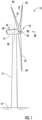
- FIG. 1 illustrates perspective view of one embodiment of a wind turbine 10 according to the present disclosure.
- the wind turbine 10 includes a tower 12 extending from a support surface 14, a nacelle 16 mounted on the tower 12, and a rotor 18 coupled to the nacelle 16.
- the rotor 18 includes a rotatable hub 20 and at least one rotor blade 22 coupled to and extending outwardly from the hub 20.
- the rotor 18 includes three rotor blades 22.
- the rotor 18 may include more or less than three rotor blades 22.
- Each rotor blade 22 may be spaced about the hub 20 to facilitate rotating the rotor 18 to enable kinetic energy to be transferred from the wind into usable mechanical energy, and subsequently, electrical energy.
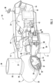
- the hub 20 may be rotatably coupled to an electric generator 24 ( FIG. 2 ) positioned within the nacelle 16 to permit electrical energy to be produced.
- a generator 24 may be disposed within the nacelle 16.
- the generator 24 may be coupled to the rotor 18 of the wind turbine 10 for generating electrical power from the rotational energy generated by the rotor 18.
- the rotor 18 may include a main shaft 40 coupled to the hub 20 for rotation therewith.
- the generator 24 may then be coupled to the main shaft 40 such that rotation of the main shaft 40 drives the generator 24.
- the generator 24 includes a generator shaft 42 rotatably coupled to the main shaft 40 through a gearbox 44.
- the generator shaft 42 may be rotatably coupled directly to the main shaft 40.
- the generator 24 may be directly rotatably coupled to the main shaft 40.
- the main shaft 40 may generally be supported within the nacelle 16 by a support frame or bedplate 46 positioned atop the wind turbine tower 12.
- the main shaft 40 may be supported by the bedplate 46 via a pair of pillow blocks 48, 50 mounted to the bedplate 46.
- the wind turbine 10 may also include a turbine control system or a turbine controller 26 within the nacelle 16.
- the turbine controller 26 is disposed within a control cabinet 52 mounted to a portion of the nacelle 16.
- the turbine controller 26 may be disposed at any location on or in the wind turbine 10, at any location on the support surface 14 or generally at any other location.
- the turbine controller 26 may generally be configured to control the various operating modes (e.g., start-up or shut-down sequences) and/or components of the wind turbine 10.
- Each rotor blade 22 may also include a pitch adjustment mechanism 32 configured to rotate each rotor blade 22 about its pitch axis 34.
- each pitch adjustment mechanism 32 may include a pitch drive motor 33 (e.g., any suitable electric, hydraulic, or pneumatic motor), a pitch drive gearbox 35, and a pitch drive pinion 37.
- the pitch drive motor 33 may be coupled to the pitch drive gearbox 35 so that the pitch drive motor 33 imparts mechanical force to the pitch drive gearbox 35.
- the pitch drive gearbox 35 may be coupled to the pitch drive pinion 37 for rotation therewith.
- the pitch drive pinion 37 may, in turn, be in rotational engagement with a pitch bearing 54 coupled between the hub 20 and a corresponding rotor blade 22 such that rotation of the pitch drive pinion 37 causes rotation of the pitch bearing 54.
- rotation of the pitch drive motor 33 drives the pitch drive gearbox 35 and the pitch drive pinion 37, thereby rotating the pitch bearing 54 and the rotor blade 22 about the pitch axis 34.
- the wind turbine 10 may include one or more yaw drive mechanisms 38 communicatively coupled to the controller 26, with each yaw drive mechanism(s) 38 being configured to change the angle of the nacelle 16 relative to the wind (e.g., by engaging a yaw bearing 56 of the wind turbine 10).
- the turbine controller 26 may also be communicatively coupled to each pitch adjustment mechanism 32 of the wind turbine 10 (one of which is shown) through a separate or integral pitch controller 30 ( FIG. 1 ) for controlling and/or altering the pitch angle of the rotor blades 22 (i.e., an angle that determines a perspective of the rotor blades 22 with respect to the direction 28 of the wind).
- one or more sensors 57, 58 may be provided on the wind turbine 10. More specifically, as shown, a wind sensor 58 may be provided on the wind turbine 10.
- the wind sensor 58 may a wind vane, and anemometer, a LIDAR sensor, or another suitable sensor that measures wind speed and/or direction.
- a pitch sensor 57 may be configured with each of the pitch drive mechanism 32, e.g. to monitor various parameters of the pitch motor 33.
- the sensors 57, 58 may further be in communication with the controller 26, and may provide related information to the controller 26.
- the pitch sensor(s) 59 may correspond to temperature sensors that send temperature signals to the controllers 26, 30 to indicate an actual temperature of the pitch batteries, which is described in more detail herein.
- the term "monitor" and variations thereof indicates that the various sensors of the wind turbine 10 may be configured to provide a direct measurement of the parameters being monitored and/or an indirect measurement of such parameters.
- the sensors described herein may, for example, be used to generate signals relating to the parameter being monitored, which can then be utilized by the controller 26 to determine the condition.
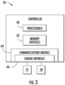
- the controller 26 may include one or more processor(s) 60 and associated memory device(s) 62 configured to perform a variety of computer-implemented functions (e.g., performing the methods, steps, calculations and the like and storing relevant data as disclosed herein). Additionally, the controller 26 may also include a communications module 64 to facilitate communications between the controller 26 and the various components of the wind turbine 10. Further, the communications module 64 may include a sensor interface 66 (e.g., one or more analog-to-digital converters) to permit signals transmitted from one or more sensors 57, 58 to be converted into signals that can be understood and processed by the processors 60.
- a sensor interface 66 e.g., one or more analog-to-digital converters
- the sensors 57, 58 may be communicatively coupled to the communications module 64 using any suitable means.
- the sensors 57, 58 are coupled to the sensor interface 66 via a wired connection.
- the sensors 57, 58 may be coupled to the sensor interface 66 via a wireless connection, such as by using any suitable wireless communications protocol known in the art.
- the term "processor” refers not only to integrated circuits referred to in the art as being included in a computer, but also refers to a controller, a microcontroller, a microcomputer, a programmable logic controller (PLC), an application specific integrated circuit, and other programmable circuits.
- the memory device(s) 62 may generally comprise memory element(s) including, but not limited to, computer readable medium (e.g., random access memory (RAM)), computer readable non-volatile medium (e.g., a flash memory), a floppy disk, a compact disc-read only memory (CD-ROM), a magneto-optical disk (MOD), a digital versatile disc (DVD) and/or other suitable memory elements.
- RAM random access memory
- CD-ROM compact disc-read only memory
- MOD magneto-optical disk
- DVD digital versatile disc
- Such memory device(s) 62 may generally be configured to store suitable computer-readable instructions that, when implemented by the processor(s) 60, configure the controller 26 to perform various functions including, but not limited to, transmitting suitable control signals to implement corrective action(s) in response to a distance signal exceeding a predetermined threshold as described herein, as well as various other suitable computer-implemented functions.
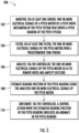
- FIG. 5 illustrates a flow diagram of an embodiment of a method 100 for preventing a pitch bearing failure of a pitch system according to the present disclosure.
- FIG. 6 illustrates a schematic diagram of one embodiment of system 150 for preventing a pitch bearing failure of a pitch system according to the present disclosure.
- FIG. 7 illustrates a schematic diagram of another embodiment of system 150 for preventing a pitch bearing failure of a pitch system according to the present disclosure.
- the method 100 is described herein as implemented using, for example, the pitch system 70 described above.
- the disclosed method 100 may be implemented using any other suitable pitch system now known or later developed in the art.
- FIG. 5 depicts steps performed in a particular order for purposes of illustration and discussion, the methods described herein are not limited to any particular order or arrangement.
- One skilled in the art, using the disclosures provided herein, will appreciate that various steps of the methods can be omitted, rearranged, combined and/or adapted in various ways.
- the method 100 includes monitoring, via at least one sensor (e.g. sensor(s) 57), one or more electrical signals of the pitch motor 33 of the pitch drive mechanism 32 of the pitch system 70.
- the electrical signal(s) may include, for example, current, voltage, power, and/or torque.
- the electrical signal(s) may be pitch current.
- the method 100 includes filtering, via at least one filter, the electrical signal(s) of the pitch motor 33 over a predetermined time period.
- the filter(s) may include a low-pass filter, a high-pass filter, a band-pass filter or combinations thereof. More specifically, as shown in FIGS. 6 and 7 , the pitch current may be filtered via a low-pass filter 152.
- the method 100 includes analyzing, e.g. via the pitch system 70 and/or the turbine controller 26, the electrical signal(s) of the pitch motor 33 so as to remove noise and amplify outliers.
- the method 100 may include determining a mean drift in the electrical signal(s) of the pitch motor 33 over the predetermined time period and removing the mean drift from the electrical signal(s) of the pitch motor 33 for the predetermined time period to reduce noise of the operational signal(s) due to an aerodynamic torsional moment on the rotor blade 22.
- the method 100 may also include removing noise due to pitch accelerating torque by detecting a component of motor torque leading pitch rate in phase by ninety degrees (90°) and removing the component from the electrical signal(s). Moreover, the method 100 may include removing noise due to aerodynamic steady state torsional torque by detecting mean drift in motor torque and removing the mean drift from the electrical signal(s). In such embodiments, the method 100 may include normalizing a metric of friction with pitch travel and bearing load, e.g. so as to further improve diagnostic accuracy and make the method 100 robust to variations in pitch travel and loads.
- the pitch system 70 may be configured to analyze the electrical signal(s) of the pitch motor 33 by altering the pitch current using at least one of a root-mean-square, a standard deviation, and/or power of the pitch motor 33 to obtain an altered current value 156.
- the turbine controller 26 may then determine a maximum value over a certain time interval, such as 10 minutes. Such maximum values may also be stored in a global data repository 162, e.g. of a farm-level controller 160.
- a global data repository 162 e.g. of a farm-level controller 160.
- the method 100 further includes estimating bearing friction of the pitch bearing 54 using the analyzed electrical signal(s) of the pitch motor 33.
- the bearing friction may be estimated by generating, via the turbine controller 26, a predictive computer model of the pitch bearing 54 using the electrical signal(s) of the pitch motor 33 and one or more operational signals of the pitch system 70.
- the operational signal(s) of the pitch system 70 may include temperature, ball bearing friction, cage stress, operational hours, thrust, brake activation, or pitching activity of the pitch drive mechanism 32.
- the pitching activity may include pitch rate, pitch motor energy per degree of pitch travel, amount of pitching, pitch angle, or any other suitable pitching activity.
- the pitch torque may be determined as a function of the pitch current.
- the pitch rate may be used to determine the pitch power, e.g. by multiplying the pitch torque by the pitch rate.
- the pitch rate may be used to determine the pitch travel, e.g. by determining the absolute value of the pitch rate as shown at 170.
- the pitch travel can also be filtered via a low-pass filter 153.
- the outputs 172, 173 of the low-pass filters 152, 153 represent an average frictional power and an average pitch travel rate, respectively.
- the controller 26 can determine the frictional work 176, which can be used to indicate an anomaly in the pitch bearing 54.
- the method 100 may include generating a heat map 164 of the pitch bearing 54 as a function of wind speed and time for the predetermined time period using the altered current value.
- the method 100 may include generating the heat map 164 of the pitch bearing 54 using a digital twin model.
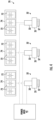
- a damaged pitch bearing FIG. 8B
- FIG. 8B a damaged pitch bearing can be easily detected, e.g. by comparing heat maps for all pitch bearings 54 across all of the rotor blades 22 of the wind turbine 10.
- the method 100 includes implementing, via the turbine controller 26, a control action when the estimated bearing friction of the pitch bearing 54 indicates an anomaly in the pitch bearing 54.
- the method 100 may include determining a frictional power loss of the pitch bearing 54, e.g. from the heat map 164.
- implementing the control action when the estimated bearing friction of the pitch bearing 54 indicates an anomaly in the pitch bearing 54 may include implementing the control action when the frictional power loss of the pitch bearing 54 exceeds a predetermined threshold.
Landscapes
- Engineering & Computer Science (AREA)
- Life Sciences & Earth Sciences (AREA)
- Sustainable Development (AREA)
- Sustainable Energy (AREA)
- Chemical & Material Sciences (AREA)
- Combustion & Propulsion (AREA)
- Mechanical Engineering (AREA)
- General Engineering & Computer Science (AREA)
- Physics & Mathematics (AREA)
- Fluid Mechanics (AREA)
- Wind Motors (AREA)
Claims (9)
- Verfahren zum Verhindern eines Ausfalls eines Pitch-Lagers eines Pitch-Systems (70) einer Windturbine (10), wobei das Verfahren umfasst:Überwachen, über mindestens einen Sensor (57, 58), eines oder mehrerer elektrischer Signale eines Pitch-Motors (33) eines Pitch-Antriebsmechanismus des Pitch-Systems (70), der ein Pitch-Lager (54) des Pitch-Systems (70) antreibt;Analysieren, über die Steuerung (26), des einen oder der mehreren elektrischen Signale des Pitch-Motors (33) um Rauschen zu entfernen und Ausreißer zu verstärken;Schätzen der Lagerreibung des Pitch-Lagers (54) unter Verwendung des analysierten einen oder der analysierten mehreren elektrischen Signale des Pitch-Motors (33); undAusführen einer Steuerungsaktion über die Steuerung (26), wenn die geschätzte Lagerreibung des Pitch-Lagers (54) eine Anomalie im Pitch-Lager (54) anzeigt;wobei das Analysieren des einen oder der mehreren elektrischen Signale des Pitch-Motors (33), um das Rauschen zu entfernen und Ausreißer zu verstärken, ferner das Filtern des einen oder der mehreren elektrischen Signale des Pitch-Motors (33) über einen vorbestimmten Zeitraum umfasst; undwobei das Filtern des einen oder der mehreren elektrischen Signale des Pitch-Motors (33) über den vorbestimmten Zeitraum ferner umfasst:Bestimmen einer mittleren Drift in dem einen oder den mehreren elektrischen Signalen des Pitch-Motors (33) über den vorbestimmten Zeitraum; undEntfernen der mittleren Drift aus dem einen oder den mehreren elektrischen Signalen des Pitch-Motors (33) für den vorbestimmten Zeitraum, um das Rauschen des einen oder der mehreren Betriebssignale aufgrund eines aerodynamischen Torsionsmoments auf dem Rotorblatt (22) zu reduzieren.
- Verfahren nach Anspruch 1, wobei das eine oder die mehreren elektrischen Signale mindestens eines der folgenden Signale umfassen: Strom, Spannung, Leistung oder Drehmoment.
- Verfahren nach einem der Ansprüche 1-2, wobei das Schätzen der Lagerreibung des Pitch-Lagers (54) unter Verwendung des analysierten einen oder der mehreren elektrischen Signale des Pitch-Motors (33) ferner das Erzeugen eines prädiktiven Computermodells des Pitch-Lagers (54) über die Steuerung (26) unter Verwendung des einen oder der mehreren elektrischen Signale des Pitch-Motors (33) und eines oder mehrerer Betriebssignale des Pitch-Systems (70) umfasst.
- Verfahren nach Anspruch 3, wobei das eine oder die mehreren Betriebssignale des Pitch-Systems (70) mindestens eines der folgenden Signale umfassen: Temperatur, Kugellagerreibung, Käfigbelastung, Betriebsstunden, Schub, Bremsaktivierung oder Pitch-Aktivität des Pitch-Antriebsmechanismus, wobei die Pitch-Aktivität mindestens eines von umfasst von: Pitch-Motorenergie pro Grad der Pitch-Bewegung, Pitch-Betrag oder Pitch-Winkel.
- Verfahren nach einem der Ansprüche 1 bis 4, wobei das eine oder die mehreren elektrischen Signale des Pitch-Motors (33) den Strom umfassen und wobei das Analysieren des einen oder der mehreren elektrischen Signale des Pitch-Motors (33), um Rauschen zu entfernen und Ausreißer zu verstärken, ferner umfasst:Ändern des Stroms unter Verwendung mindestens eines Effektivwerts, einer Standardabweichung oder einer Leistung des Pitch-Motors (33), um einen geänderten Stromwert zu erhalten; undErzeugen einer Wärmekarte (164) des Pitch-Lagers (54) als Funktion der Windgeschwindigkeit und der Zeit für den vorbestimmten Zeitraum unter Verwendung des geänderten Stromwerts.
- Verfahren nach einem der Ansprüche 1 bis 5, wobei das Schätzen der Lagerreibung des Blattlagers (54) unter Verwendung des analysierten einen oder der mehreren elektrischen Signale des Pitch-Motors (33) ferner das Bestimmen eines Reibungsverlusts des Blattlagers (54) aus der Wärmekarte (164) umfasst.
- System zum Verhindern eines Ausfalls eines Blattlagers eines Pitch-Systems (70) einer Windturbine (10), wobei das System umfasst:mindestens einen Sensor (57, 58), der zum Überwachen eines oder mehrerer elektrischer Signale eines Pitch-Motors (33) eines Pitch-Antriebsmechanismus des Pitch-Systems (70) konfiguriert ist, der ein Pitch-Lager (54) des Pitch-Systems (70) antreibt;eine Steuerung (26), die mit dem mindestens einen Sensor (57, 58) kommunikativ gekoppelt ist, wobei die Steuerung (26) mindestens einen Prozessor (60) umfasst, der so konfiguriert ist, dass er eine Vielzahl von Operationen ausführt, wobei die Vielzahl von Operationen umfasst:Analysieren des einen oder der mehreren elektrischen Signale des Pitch-Motors (33), um Rauschen zu entfernen und Ausreißer zu verstärken;Schätzen der Lagerreibung des Blattlagers (54) unter Verwendung des analysierten einen oder der mehreren elektrischen Signale des Pitch-Motors (33); undAusführen einer Steuerungsaktion, wenn die geschätzte Lagerreibung des Pitch-Lagers (54) eine Anomalie im Pitch-Lager (54) anzeigt;wobei das Analysieren des einen oder der mehreren elektrischen Signale des Pitch-Motors (33), um das Rauschen zu entfernen und Ausreißer zu verstärken, ferner das Filtern des einen oder der mehreren elektrischen Signale des Pitch-Motors (33) über einen vorbestimmten Zeitraum umfasst; undwobei das Filtern des einen oder der mehreren elektrischen Signale des Pitch-Motors (33) über den vorbestimmten Zeitraum ferner umfasst:Bestimmen einer mittleren Drift in dem einen oder den mehreren elektrischen Signalen des Pitch-Motors (33) über den vorbestimmten Zeitraum; undEntfernen der mittleren Drift aus dem einen oder den mehreren elektrischen Signalen des Pitch-Motors (33) für den vorbestimmten Zeitraum, um das Rauschen des einen oder der mehreren Betriebssignale zu reduzieren.
- System nach Anspruch 7, wobei das eine oder die mehreren elektrischen Signale mindestens eines von Strom, Spannung, Leistung oder Drehmoment umfasst.
- System nach einem der Ansprüche 7 bis 8, wobei die Schätzung der Lagerreibung des Blattlagers (54) unter Verwendung des analysierten einen oder der mehreren elektrischen Signale des Pitch-Motors (33) ferner die Erzeugung eines prädiktiven Computermodells des Pitch-Lagers (54) unter Verwendung des einen oder der mehreren elektrischen Signale des Pitch-Motors (33) und eines oder mehrerer Betriebssignale des Pitch-Systems (70) umfasst.
Applications Claiming Priority (1)
| Application Number | Priority Date | Filing Date | Title |
|---|---|---|---|
| PCT/US2019/058693 WO2021086338A1 (en) | 2019-10-30 | 2019-10-30 | System and method for preventing pitch bearing failures in a wind turbine using pitch motor signals |
Publications (2)
| Publication Number | Publication Date |
|---|---|
| EP4051898A1 EP4051898A1 (de) | 2022-09-07 |
| EP4051898B1 true EP4051898B1 (de) | 2024-11-27 |
Family
ID=68582507
Family Applications (1)
| Application Number | Title | Priority Date | Filing Date |
|---|---|---|---|
| EP19805092.4A Active EP4051898B1 (de) | 2019-10-30 | 2019-10-30 | System und verfahren zur verhinderung von pitchlagerausfällen bei einer windturbine unter verwendung von pitchmotorsignalen |
Country Status (6)
| Country | Link |
|---|---|
| US (1) | US12012930B2 (de) |
| EP (1) | EP4051898B1 (de) |
| CN (1) | CN114641610B (de) |
| DK (1) | DK4051898T3 (de) |
| ES (1) | ES3007810T3 (de) |
| WO (1) | WO2021086338A1 (de) |
Families Citing this family (5)
| Publication number | Priority date | Publication date | Assignee | Title |
|---|---|---|---|---|
| EP3702612A1 (de) * | 2019-02-27 | 2020-09-02 | B&R Industrial Automation GmbH | Verfahren zum halten eines beweglichen teils einer windkraftanlage |
| CN113323803B (zh) * | 2021-05-12 | 2023-02-21 | 东方电气风电股份有限公司 | 一种基于风机动态控制的变桨轴承检测方法 |
| US11767821B2 (en) | 2021-11-29 | 2023-09-26 | General Electric Renovables Espana, S.L. | System and method for responding to a friction coefficient signal of a wind turbine |
| CN115478994A (zh) * | 2022-10-11 | 2022-12-16 | 中车株洲电力机车研究所有限公司 | 一种变桨轴承运行状态评估方法、介质及系统 |
| EP4542031A1 (de) * | 2023-10-19 | 2025-04-23 | Nordex Energy Spain, S.A.U. | Verfahren zum betreiben einer windenergieanlage und windenergieanlage |
Family Cites Families (23)
| Publication number | Priority date | Publication date | Assignee | Title |
|---|---|---|---|---|
| US6600240B2 (en) * | 1997-08-08 | 2003-07-29 | General Electric Company | Variable speed wind turbine generator |
| US6812587B2 (en) * | 2001-02-05 | 2004-11-02 | Capstone Turbine Corporation | Continuous power supply with back-up generation |
| WO2006071150A1 (en) * | 2004-12-27 | 2006-07-06 | Abb Research Ltd. | Electric power flow control |
| WO2009010061A2 (en) * | 2007-07-14 | 2009-01-22 | Vestas Wind Systems A/S | A wind turbine, a method for compensating for disparities in a wind turbine rotor blade pitch system and use of a method. |
| EP2037119B1 (de) * | 2007-09-12 | 2011-10-26 | Siemens Aktiengesellschaft | Giersteuerungsystem für Windturbine und Verfahren zur Giermomentverringerung in einem solchen System |
| US8482147B2 (en) * | 2009-07-21 | 2013-07-09 | George Moser | Wind turbine with powered synchronization system |
| US8317462B2 (en) * | 2011-04-26 | 2012-11-27 | General Electric Company | System for actively monitoring wear on wind turbine brake pads and related methods |
| KR101375266B1 (ko) * | 2012-02-10 | 2014-03-17 | 삼성중공업 주식회사 | 풍력발전기의 독립 피치 제어 시스템 및 그 방법 |
| US9631606B2 (en) * | 2014-04-14 | 2017-04-25 | General Electric Company | System and method for thrust-speed control of a wind turbine |
| CN105134510A (zh) | 2015-09-18 | 2015-12-09 | 北京中恒博瑞数字电力科技有限公司 | 一种风力发电机组变桨系统的状态监测和故障诊断方法 |
| DE102016208051A1 (de) * | 2016-05-10 | 2017-11-16 | Wobben Properties Gmbh | Windenergieanlagen-Rotorblatt, und Windenergieanlage mit selbigem |
| US10273940B2 (en) * | 2016-05-12 | 2019-04-30 | General Electric Company | System and method for detecting pitch bearing damage in a wind turbine |
| CN106930907B (zh) | 2017-04-27 | 2019-01-15 | 湘电风能有限公司 | 一种风力涡轮机变桨轴承降载装置 |
| CN107689059B (zh) | 2017-06-30 | 2020-01-31 | 北京金风科创风电设备有限公司 | 风力发电机组变桨异常的识别方法及装置 |
| CN107327367B (zh) | 2017-06-30 | 2018-12-07 | 北京金风科创风电设备有限公司 | 风力发电机组变桨异常的识别方法及装置 |
| JP6952312B2 (ja) * | 2017-09-25 | 2021-10-20 | 青島大学Qingdao University | ピッチ制御システム |
| ES2858575T3 (es) * | 2017-10-13 | 2021-09-30 | Gen Electric | Procedimiento para mitigar cargas descontroladas de pala en caso de un fallo de sistema de pitch |
| CN207485607U (zh) * | 2017-11-09 | 2018-06-12 | 西安热工研究院有限公司 | 一种风力机变桨轴承故障检测系统 |
| CN108035848A (zh) * | 2017-11-21 | 2018-05-15 | 明阳智慧能源集团股份公司 | 一种风力发电机组基于塔顶载荷的独立变桨控制方法 |
| US11473564B2 (en) * | 2018-01-18 | 2022-10-18 | General Electric Company | System and method for monitoring a wind turbine pitch bearing |
| CN108932580A (zh) | 2018-06-05 | 2018-12-04 | 浙江运达风电股份有限公司 | 基于数据建模的风电机组变桨轴承磨损监测和预警方法 |
| CN109444740B (zh) | 2018-11-14 | 2020-10-02 | 湖南大学 | 一种风电机组的故障状态智能监测与诊断方法 |
| US11767821B2 (en) * | 2021-11-29 | 2023-09-26 | General Electric Renovables Espana, S.L. | System and method for responding to a friction coefficient signal of a wind turbine |
-
2019
- 2019-10-30 DK DK19805092.4T patent/DK4051898T3/da active
- 2019-10-30 CN CN201980101873.2A patent/CN114641610B/zh active Active
- 2019-10-30 US US17/772,685 patent/US12012930B2/en active Active
- 2019-10-30 WO PCT/US2019/058693 patent/WO2021086338A1/en not_active Ceased
- 2019-10-30 EP EP19805092.4A patent/EP4051898B1/de active Active
- 2019-10-30 ES ES19805092T patent/ES3007810T3/es active Active
Also Published As
| Publication number | Publication date |
|---|---|
| US20230003192A1 (en) | 2023-01-05 |
| EP4051898A1 (de) | 2022-09-07 |
| CN114641610A (zh) | 2022-06-17 |
| DK4051898T3 (da) | 2025-03-03 |
| WO2021086338A1 (en) | 2021-05-06 |
| CN114641610B (zh) | 2025-09-05 |
| ES3007810T3 (en) | 2025-03-20 |
| US12012930B2 (en) | 2024-06-18 |
Similar Documents
| Publication | Publication Date | Title |
|---|---|---|
| US12012930B2 (en) | System and method for preventing pitch bearing failures in a wind turbine using pitch motor signals | |
| EP3514376B1 (de) | System und verfahren zur überwachung eines windenergieanlagen-pitchlagers | |
| DK177922B1 (en) | Method and system for monitoring wind turbine | |
| US9624905B2 (en) | System and method for preventing excessive loading on a wind turbine | |
| US10935001B2 (en) | System and method for monitoring wear on a gearbox of a wind turbine | |
| EP3771823B1 (de) | Systeme und verfahren zur detektion von schäden in drehmaschinen | |
| DK2607694T3 (en) | Process for operating a wind turbine | |
| EP4187086B1 (de) | System und verfahren zur reaktion auf ein reibungskoeffizientensignal einer windturbine | |
| US20170306926A1 (en) | System and method for estimating high bandwidth tower deflection for wind turbines | |
| EP3796016B1 (de) | System und verfahren zur erkennung von batteriefehlern in einem anstellsystem einer windturbine | |
| EP3722596B1 (de) | System und verfahren zur minderung von schäden in einem rotorblatt einer windturbine | |
| JP6935297B2 (ja) | 風力発電システム | |
| EP3722597B1 (de) | System und verfahren zur verhinderung von katastrophalen schäden im antriebsstrang einer windturbine | |
| EP4332374A1 (de) | System und verfahren zur erkennung und reaktion auf rotorblattschäden bei einer windturbine |
Legal Events
| Date | Code | Title | Description |
|---|---|---|---|
| STAA | Information on the status of an ep patent application or granted ep patent |
Free format text: STATUS: UNKNOWN |
|
| STAA | Information on the status of an ep patent application or granted ep patent |
Free format text: STATUS: THE INTERNATIONAL PUBLICATION HAS BEEN MADE |
|
| PUAI | Public reference made under article 153(3) epc to a published international application that has entered the european phase |
Free format text: ORIGINAL CODE: 0009012 |
|
| STAA | Information on the status of an ep patent application or granted ep patent |
Free format text: STATUS: REQUEST FOR EXAMINATION WAS MADE |
|
| 17P | Request for examination filed |
Effective date: 20220512 |
|
| AK | Designated contracting states |
Kind code of ref document: A1 Designated state(s): AL AT BE BG CH CY CZ DE DK EE ES FI FR GB GR HR HU IE IS IT LI LT LU LV MC MK MT NL NO PL PT RO RS SE SI SK SM TR |
|
| DAV | Request for validation of the european patent (deleted) | ||
| DAX | Request for extension of the european patent (deleted) | ||
| P01 | Opt-out of the competence of the unified patent court (upc) registered |
Effective date: 20230530 |
|
| RAP1 | Party data changed (applicant data changed or rights of an application transferred) |
Owner name: GENERAL ELECTRIC RENOVABLES ESPANA, S.L. |
|
| STAA | Information on the status of an ep patent application or granted ep patent |
Free format text: STATUS: EXAMINATION IS IN PROGRESS |
|
| 17Q | First examination report despatched |
Effective date: 20240404 |
|
| GRAP | Despatch of communication of intention to grant a patent |
Free format text: ORIGINAL CODE: EPIDOSNIGR1 |
|
| STAA | Information on the status of an ep patent application or granted ep patent |
Free format text: STATUS: GRANT OF PATENT IS INTENDED |
|
| INTG | Intention to grant announced |
Effective date: 20240709 |
|
| GRAS | Grant fee paid |
Free format text: ORIGINAL CODE: EPIDOSNIGR3 |
|
| GRAA | (expected) grant |
Free format text: ORIGINAL CODE: 0009210 |
|
| STAA | Information on the status of an ep patent application or granted ep patent |
Free format text: STATUS: THE PATENT HAS BEEN GRANTED |
|
| AK | Designated contracting states |
Kind code of ref document: B1 Designated state(s): AL AT BE BG CH CY CZ DE DK EE ES FI FR GB GR HR HU IE IS IT LI LT LU LV MC MK MT NL NO PL PT RO RS SE SI SK SM TR |
|
| REG | Reference to a national code |
Ref country code: GB Ref legal event code: FG4D |
|
| REG | Reference to a national code |
Ref country code: CH Ref legal event code: EP |
|
| REG | Reference to a national code |
Ref country code: DE Ref legal event code: R096 Ref document number: 602019062653 Country of ref document: DE |
|
| REG | Reference to a national code |
Ref country code: IE Ref legal event code: FG4D |
|
| REG | Reference to a national code |
Ref country code: DK Ref legal event code: T3 Effective date: 20250226 |
|
| REG | Reference to a national code |
Ref country code: ES Ref legal event code: FG2A Ref document number: 3007810 Country of ref document: ES Kind code of ref document: T3 Effective date: 20250320 |
|
| REG | Reference to a national code |
Ref country code: LT Ref legal event code: MG9D |
|
| REG | Reference to a national code |
Ref country code: NL Ref legal event code: MP Effective date: 20241127 |
|
| PG25 | Lapsed in a contracting state [announced via postgrant information from national office to epo] |
Ref country code: PT Free format text: LAPSE BECAUSE OF FAILURE TO SUBMIT A TRANSLATION OF THE DESCRIPTION OR TO PAY THE FEE WITHIN THE PRESCRIBED TIME-LIMIT Effective date: 20250327 Ref country code: IS Free format text: LAPSE BECAUSE OF FAILURE TO SUBMIT A TRANSLATION OF THE DESCRIPTION OR TO PAY THE FEE WITHIN THE PRESCRIBED TIME-LIMIT Effective date: 20250327 Ref country code: HR Free format text: LAPSE BECAUSE OF FAILURE TO SUBMIT A TRANSLATION OF THE DESCRIPTION OR TO PAY THE FEE WITHIN THE PRESCRIBED TIME-LIMIT Effective date: 20241127 |
|
| PG25 | Lapsed in a contracting state [announced via postgrant information from national office to epo] |
Ref country code: FI Free format text: LAPSE BECAUSE OF FAILURE TO SUBMIT A TRANSLATION OF THE DESCRIPTION OR TO PAY THE FEE WITHIN THE PRESCRIBED TIME-LIMIT Effective date: 20241127 Ref country code: NL Free format text: LAPSE BECAUSE OF FAILURE TO SUBMIT A TRANSLATION OF THE DESCRIPTION OR TO PAY THE FEE WITHIN THE PRESCRIBED TIME-LIMIT Effective date: 20241127 |
|
| REG | Reference to a national code |
Ref country code: AT Ref legal event code: MK05 Ref document number: 1745942 Country of ref document: AT Kind code of ref document: T Effective date: 20241127 |
|
| PG25 | Lapsed in a contracting state [announced via postgrant information from national office to epo] |
Ref country code: BG Free format text: LAPSE BECAUSE OF FAILURE TO SUBMIT A TRANSLATION OF THE DESCRIPTION OR TO PAY THE FEE WITHIN THE PRESCRIBED TIME-LIMIT Effective date: 20241127 |
|
| PG25 | Lapsed in a contracting state [announced via postgrant information from national office to epo] |
Ref country code: NO Free format text: LAPSE BECAUSE OF FAILURE TO SUBMIT A TRANSLATION OF THE DESCRIPTION OR TO PAY THE FEE WITHIN THE PRESCRIBED TIME-LIMIT Effective date: 20250227 |
|
| PG25 | Lapsed in a contracting state [announced via postgrant information from national office to epo] |
Ref country code: LV Free format text: LAPSE BECAUSE OF FAILURE TO SUBMIT A TRANSLATION OF THE DESCRIPTION OR TO PAY THE FEE WITHIN THE PRESCRIBED TIME-LIMIT Effective date: 20241127 Ref country code: AT Free format text: LAPSE BECAUSE OF FAILURE TO SUBMIT A TRANSLATION OF THE DESCRIPTION OR TO PAY THE FEE WITHIN THE PRESCRIBED TIME-LIMIT Effective date: 20241127 Ref country code: GR Free format text: LAPSE BECAUSE OF FAILURE TO SUBMIT A TRANSLATION OF THE DESCRIPTION OR TO PAY THE FEE WITHIN THE PRESCRIBED TIME-LIMIT Effective date: 20250228 |
|
| PG25 | Lapsed in a contracting state [announced via postgrant information from national office to epo] |
Ref country code: PL Free format text: LAPSE BECAUSE OF FAILURE TO SUBMIT A TRANSLATION OF THE DESCRIPTION OR TO PAY THE FEE WITHIN THE PRESCRIBED TIME-LIMIT Effective date: 20241127 |
|
| PG25 | Lapsed in a contracting state [announced via postgrant information from national office to epo] |
Ref country code: RS Free format text: LAPSE BECAUSE OF FAILURE TO SUBMIT A TRANSLATION OF THE DESCRIPTION OR TO PAY THE FEE WITHIN THE PRESCRIBED TIME-LIMIT Effective date: 20250227 |
|
| PG25 | Lapsed in a contracting state [announced via postgrant information from national office to epo] |
Ref country code: SM Free format text: LAPSE BECAUSE OF FAILURE TO SUBMIT A TRANSLATION OF THE DESCRIPTION OR TO PAY THE FEE WITHIN THE PRESCRIBED TIME-LIMIT Effective date: 20241127 |
|
| PG25 | Lapsed in a contracting state [announced via postgrant information from national office to epo] |
Ref country code: EE Free format text: LAPSE BECAUSE OF FAILURE TO SUBMIT A TRANSLATION OF THE DESCRIPTION OR TO PAY THE FEE WITHIN THE PRESCRIBED TIME-LIMIT Effective date: 20241127 |
|
| PG25 | Lapsed in a contracting state [announced via postgrant information from national office to epo] |
Ref country code: RO Free format text: LAPSE BECAUSE OF FAILURE TO SUBMIT A TRANSLATION OF THE DESCRIPTION OR TO PAY THE FEE WITHIN THE PRESCRIBED TIME-LIMIT Effective date: 20241127 |
|
| PG25 | Lapsed in a contracting state [announced via postgrant information from national office to epo] |
Ref country code: SK Free format text: LAPSE BECAUSE OF FAILURE TO SUBMIT A TRANSLATION OF THE DESCRIPTION OR TO PAY THE FEE WITHIN THE PRESCRIBED TIME-LIMIT Effective date: 20241127 |
|
| PG25 | Lapsed in a contracting state [announced via postgrant information from national office to epo] |
Ref country code: CZ Free format text: LAPSE BECAUSE OF FAILURE TO SUBMIT A TRANSLATION OF THE DESCRIPTION OR TO PAY THE FEE WITHIN THE PRESCRIBED TIME-LIMIT Effective date: 20241127 |
|
| PG25 | Lapsed in a contracting state [announced via postgrant information from national office to epo] |
Ref country code: IT Free format text: LAPSE BECAUSE OF FAILURE TO SUBMIT A TRANSLATION OF THE DESCRIPTION OR TO PAY THE FEE WITHIN THE PRESCRIBED TIME-LIMIT Effective date: 20241127 |
|
| REG | Reference to a national code |
Ref country code: DE Ref legal event code: R097 Ref document number: 602019062653 Country of ref document: DE |
|
| PG25 | Lapsed in a contracting state [announced via postgrant information from national office to epo] |
Ref country code: SE Free format text: LAPSE BECAUSE OF FAILURE TO SUBMIT A TRANSLATION OF THE DESCRIPTION OR TO PAY THE FEE WITHIN THE PRESCRIBED TIME-LIMIT Effective date: 20241127 |
|
| PLBE | No opposition filed within time limit |
Free format text: ORIGINAL CODE: 0009261 |
|
| STAA | Information on the status of an ep patent application or granted ep patent |
Free format text: STATUS: NO OPPOSITION FILED WITHIN TIME LIMIT |
|
| PGFP | Annual fee paid to national office [announced via postgrant information from national office to epo] |
Ref country code: DK Payment date: 20250923 Year of fee payment: 7 |
|
| 26N | No opposition filed |
Effective date: 20250828 |
|
| PGFP | Annual fee paid to national office [announced via postgrant information from national office to epo] |
Ref country code: DE Payment date: 20250923 Year of fee payment: 7 |
|
| PGFP | Annual fee paid to national office [announced via postgrant information from national office to epo] |
Ref country code: ES Payment date: 20251103 Year of fee payment: 7 |