EP3454029B1 - Capsule haute pression dotée du revêtement - Google Patents
Capsule haute pression dotée du revêtement Download PDFInfo
- Publication number
- EP3454029B1 EP3454029B1 EP17190525.0A EP17190525A EP3454029B1 EP 3454029 B1 EP3454029 B1 EP 3454029B1 EP 17190525 A EP17190525 A EP 17190525A EP 3454029 B1 EP3454029 B1 EP 3454029B1
- Authority
- EP
- European Patent Office
- Prior art keywords
- coating
- crucible
- pressure capsule
- amorphous carbon
- lid
- Prior art date
- Legal status (The legal status is an assumption and is not a legal conclusion. Google has not performed a legal analysis and makes no representation as to the accuracy of the status listed.)
- Active
Links
- 238000000576 coating method Methods 0.000 title claims description 114
- 239000011248 coating agent Substances 0.000 title claims description 109
- 239000002775 capsule Substances 0.000 title claims description 90
- 239000010410 layer Substances 0.000 claims description 84
- 229910003481 amorphous carbon Inorganic materials 0.000 claims description 75
- 238000005259 measurement Methods 0.000 claims description 26
- PCHJSUWPFVWCPO-UHFFFAOYSA-N gold Chemical compound [Au] PCHJSUWPFVWCPO-UHFFFAOYSA-N 0.000 claims description 25
- 239000010931 gold Substances 0.000 claims description 25
- 229910052737 gold Inorganic materials 0.000 claims description 25
- 229910000831 Steel Inorganic materials 0.000 claims description 22
- 239000010959 steel Substances 0.000 claims description 22
- 239000012790 adhesive layer Substances 0.000 claims description 17
- 229910052751 metal Inorganic materials 0.000 claims description 14
- 239000002184 metal Substances 0.000 claims description 14
- 239000001257 hydrogen Substances 0.000 claims description 13
- 229910052739 hydrogen Inorganic materials 0.000 claims description 13
- UFHFLCQGNIYNRP-UHFFFAOYSA-N Hydrogen Chemical compound [H][H] UFHFLCQGNIYNRP-UHFFFAOYSA-N 0.000 claims description 12
- 238000000034 method Methods 0.000 claims description 12
- 239000000126 substance Substances 0.000 claims description 9
- 229910052799 carbon Inorganic materials 0.000 claims description 8
- RTAQQCXQSZGOHL-UHFFFAOYSA-N Titanium Chemical compound [Ti] RTAQQCXQSZGOHL-UHFFFAOYSA-N 0.000 claims description 6
- 238000000151 deposition Methods 0.000 claims description 6
- 239000010936 titanium Substances 0.000 claims description 6
- 229910052719 titanium Inorganic materials 0.000 claims description 6
- SJKRCWUQJZIWQB-UHFFFAOYSA-N azane;chromium Chemical compound N.[Cr] SJKRCWUQJZIWQB-UHFFFAOYSA-N 0.000 claims description 4
- 230000008021 deposition Effects 0.000 claims description 4
- 238000004519 manufacturing process Methods 0.000 claims description 4
- 150000004767 nitrides Chemical class 0.000 claims description 4
- 150000002431 hydrogen Chemical class 0.000 claims description 3
- 238000004544 sputter deposition Methods 0.000 claims description 2
- 238000005229 chemical vapour deposition Methods 0.000 claims 1
- 125000004435 hydrogen atom Chemical group [H]* 0.000 claims 1
- 238000005240 physical vapour deposition Methods 0.000 claims 1
- 238000000623 plasma-assisted chemical vapour deposition Methods 0.000 claims 1
- 239000000523 sample Substances 0.000 description 26
- MHAJPDPJQMAIIY-UHFFFAOYSA-N Hydrogen peroxide Chemical compound OO MHAJPDPJQMAIIY-UHFFFAOYSA-N 0.000 description 18
- 239000000463 material Substances 0.000 description 10
- 239000011521 glass Substances 0.000 description 9
- 239000003708 ampul Substances 0.000 description 7
- 230000003993 interaction Effects 0.000 description 6
- OKTJSMMVPCPJKN-UHFFFAOYSA-N Carbon Chemical compound [C] OKTJSMMVPCPJKN-UHFFFAOYSA-N 0.000 description 5
- XEEYBQQBJWHFJM-UHFFFAOYSA-N Iron Chemical compound [Fe] XEEYBQQBJWHFJM-UHFFFAOYSA-N 0.000 description 4
- 238000000354 decomposition reaction Methods 0.000 description 4
- 230000008569 process Effects 0.000 description 4
- 238000003466 welding Methods 0.000 description 4
- 230000003197 catalytic effect Effects 0.000 description 3
- 238000006243 chemical reaction Methods 0.000 description 3
- 230000002093 peripheral effect Effects 0.000 description 3
- 238000007789 sealing Methods 0.000 description 3
- IJGRMHOSHXDMSA-UHFFFAOYSA-N Atomic nitrogen Chemical compound N#N IJGRMHOSHXDMSA-UHFFFAOYSA-N 0.000 description 2
- VYPSYNLAJGMNEJ-UHFFFAOYSA-N Silicium dioxide Chemical compound O=[Si]=O VYPSYNLAJGMNEJ-UHFFFAOYSA-N 0.000 description 2
- QVGXLLKOCUKJST-UHFFFAOYSA-N atomic oxygen Chemical compound [O] QVGXLLKOCUKJST-UHFFFAOYSA-N 0.000 description 2
- 230000004888 barrier function Effects 0.000 description 2
- 230000008901 benefit Effects 0.000 description 2
- 238000007707 calorimetry Methods 0.000 description 2
- 230000000052 comparative effect Effects 0.000 description 2
- 238000005260 corrosion Methods 0.000 description 2
- 230000007797 corrosion Effects 0.000 description 2
- 238000009792 diffusion process Methods 0.000 description 2
- 239000007789 gas Substances 0.000 description 2
- 229910052742 iron Inorganic materials 0.000 description 2
- 239000012528 membrane Substances 0.000 description 2
- 239000001301 oxygen Substances 0.000 description 2
- 229910052760 oxygen Inorganic materials 0.000 description 2
- 238000003825 pressing Methods 0.000 description 2
- 230000009257 reactivity Effects 0.000 description 2
- 239000007787 solid Substances 0.000 description 2
- 239000000758 substrate Substances 0.000 description 2
- GPRLSGONYQIRFK-MNYXATJNSA-N triton Chemical compound [3H+] GPRLSGONYQIRFK-MNYXATJNSA-N 0.000 description 2
- 238000009736 wetting Methods 0.000 description 2
- ZOXJGFHDIHLPTG-UHFFFAOYSA-N Boron Chemical compound [B] ZOXJGFHDIHLPTG-UHFFFAOYSA-N 0.000 description 1
- 239000004215 Carbon black (E152) Substances 0.000 description 1
- PXGOKWXKJXAPGV-UHFFFAOYSA-N Fluorine Chemical compound FF PXGOKWXKJXAPGV-UHFFFAOYSA-N 0.000 description 1
- XUIMIQQOPSSXEZ-UHFFFAOYSA-N Silicon Chemical compound [Si] XUIMIQQOPSSXEZ-UHFFFAOYSA-N 0.000 description 1
- 238000005299 abrasion Methods 0.000 description 1
- CXOWYMLTGOFURZ-UHFFFAOYSA-N azanylidynechromium Chemical compound [Cr]#N CXOWYMLTGOFURZ-UHFFFAOYSA-N 0.000 description 1
- 229910052796 boron Inorganic materials 0.000 description 1
- 239000003054 catalyst Substances 0.000 description 1
- 238000006555 catalytic reaction Methods 0.000 description 1
- 229910052729 chemical element Inorganic materials 0.000 description 1
- 238000012824 chemical production Methods 0.000 description 1
- 238000005352 clarification Methods 0.000 description 1
- 238000002485 combustion reaction Methods 0.000 description 1
- 238000010586 diagram Methods 0.000 description 1
- 229910003460 diamond Inorganic materials 0.000 description 1
- 239000010432 diamond Substances 0.000 description 1
- 229910052731 fluorine Inorganic materials 0.000 description 1
- 239000011737 fluorine Substances 0.000 description 1
- 229910021385 hard carbon Inorganic materials 0.000 description 1
- 239000000383 hazardous chemical Substances 0.000 description 1
- 238000010438 heat treatment Methods 0.000 description 1
- 229930195733 hydrocarbon Natural products 0.000 description 1
- 150000002430 hydrocarbons Chemical class 0.000 description 1
- 229910044991 metal oxide Inorganic materials 0.000 description 1
- 150000004706 metal oxides Chemical class 0.000 description 1
- 229910052757 nitrogen Inorganic materials 0.000 description 1
- 229910000510 noble metal Inorganic materials 0.000 description 1
- 239000000047 product Substances 0.000 description 1
- 238000003908 quality control method Methods 0.000 description 1
- 239000011541 reaction mixture Substances 0.000 description 1
- 230000035484 reaction time Effects 0.000 description 1
- 239000010703 silicon Substances 0.000 description 1
- 229910052710 silicon Inorganic materials 0.000 description 1
- 235000012239 silicon dioxide Nutrition 0.000 description 1
- 239000000377 silicon dioxide Substances 0.000 description 1
- 239000002356 single layer Substances 0.000 description 1
- 229910001220 stainless steel Inorganic materials 0.000 description 1
- 239000010935 stainless steel Substances 0.000 description 1
- 239000007858 starting material Substances 0.000 description 1
- 238000003860 storage Methods 0.000 description 1
- 239000012815 thermoplastic material Substances 0.000 description 1
- XLYOFNOQVPJJNP-UHFFFAOYSA-N water Substances O XLYOFNOQVPJJNP-UHFFFAOYSA-N 0.000 description 1
Images


Classifications
-
- C—CHEMISTRY; METALLURGY
- C23—COATING METALLIC MATERIAL; COATING MATERIAL WITH METALLIC MATERIAL; CHEMICAL SURFACE TREATMENT; DIFFUSION TREATMENT OF METALLIC MATERIAL; COATING BY VACUUM EVAPORATION, BY SPUTTERING, BY ION IMPLANTATION OR BY CHEMICAL VAPOUR DEPOSITION, IN GENERAL; INHIBITING CORROSION OF METALLIC MATERIAL OR INCRUSTATION IN GENERAL
- C23C—COATING METALLIC MATERIAL; COATING MATERIAL WITH METALLIC MATERIAL; SURFACE TREATMENT OF METALLIC MATERIAL BY DIFFUSION INTO THE SURFACE, BY CHEMICAL CONVERSION OR SUBSTITUTION; COATING BY VACUUM EVAPORATION, BY SPUTTERING, BY ION IMPLANTATION OR BY CHEMICAL VAPOUR DEPOSITION, IN GENERAL
- C23C14/00—Coating by vacuum evaporation, by sputtering or by ion implantation of the coating forming material
- C23C14/06—Coating by vacuum evaporation, by sputtering or by ion implantation of the coating forming material characterised by the coating material
- C23C14/0605—Carbon
- C23C14/0611—Diamond
-
- B—PERFORMING OPERATIONS; TRANSPORTING
- B01—PHYSICAL OR CHEMICAL PROCESSES OR APPARATUS IN GENERAL
- B01L—CHEMICAL OR PHYSICAL LABORATORY APPARATUS FOR GENERAL USE
- B01L3/00—Containers or dishes for laboratory use, e.g. laboratory glassware; Droppers
- B01L3/04—Crucibles
-
- C—CHEMISTRY; METALLURGY
- C23—COATING METALLIC MATERIAL; COATING MATERIAL WITH METALLIC MATERIAL; CHEMICAL SURFACE TREATMENT; DIFFUSION TREATMENT OF METALLIC MATERIAL; COATING BY VACUUM EVAPORATION, BY SPUTTERING, BY ION IMPLANTATION OR BY CHEMICAL VAPOUR DEPOSITION, IN GENERAL; INHIBITING CORROSION OF METALLIC MATERIAL OR INCRUSTATION IN GENERAL
- C23C—COATING METALLIC MATERIAL; COATING MATERIAL WITH METALLIC MATERIAL; SURFACE TREATMENT OF METALLIC MATERIAL BY DIFFUSION INTO THE SURFACE, BY CHEMICAL CONVERSION OR SUBSTITUTION; COATING BY VACUUM EVAPORATION, BY SPUTTERING, BY ION IMPLANTATION OR BY CHEMICAL VAPOUR DEPOSITION, IN GENERAL
- C23C14/00—Coating by vacuum evaporation, by sputtering or by ion implantation of the coating forming material
- C23C14/02—Pretreatment of the material to be coated
- C23C14/024—Deposition of sublayers, e.g. to promote adhesion of the coating
- C23C14/025—Metallic sublayers
-
- C—CHEMISTRY; METALLURGY
- C23—COATING METALLIC MATERIAL; COATING MATERIAL WITH METALLIC MATERIAL; CHEMICAL SURFACE TREATMENT; DIFFUSION TREATMENT OF METALLIC MATERIAL; COATING BY VACUUM EVAPORATION, BY SPUTTERING, BY ION IMPLANTATION OR BY CHEMICAL VAPOUR DEPOSITION, IN GENERAL; INHIBITING CORROSION OF METALLIC MATERIAL OR INCRUSTATION IN GENERAL
- C23C—COATING METALLIC MATERIAL; COATING MATERIAL WITH METALLIC MATERIAL; SURFACE TREATMENT OF METALLIC MATERIAL BY DIFFUSION INTO THE SURFACE, BY CHEMICAL CONVERSION OR SUBSTITUTION; COATING BY VACUUM EVAPORATION, BY SPUTTERING, BY ION IMPLANTATION OR BY CHEMICAL VAPOUR DEPOSITION, IN GENERAL
- C23C14/00—Coating by vacuum evaporation, by sputtering or by ion implantation of the coating forming material
- C23C14/04—Coating on selected surface areas, e.g. using masks
- C23C14/046—Coating cavities or hollow spaces, e.g. interior of tubes; Infiltration of porous substrates
-
- C—CHEMISTRY; METALLURGY
- C23—COATING METALLIC MATERIAL; COATING MATERIAL WITH METALLIC MATERIAL; CHEMICAL SURFACE TREATMENT; DIFFUSION TREATMENT OF METALLIC MATERIAL; COATING BY VACUUM EVAPORATION, BY SPUTTERING, BY ION IMPLANTATION OR BY CHEMICAL VAPOUR DEPOSITION, IN GENERAL; INHIBITING CORROSION OF METALLIC MATERIAL OR INCRUSTATION IN GENERAL
- C23C—COATING METALLIC MATERIAL; COATING MATERIAL WITH METALLIC MATERIAL; SURFACE TREATMENT OF METALLIC MATERIAL BY DIFFUSION INTO THE SURFACE, BY CHEMICAL CONVERSION OR SUBSTITUTION; COATING BY VACUUM EVAPORATION, BY SPUTTERING, BY ION IMPLANTATION OR BY CHEMICAL VAPOUR DEPOSITION, IN GENERAL
- C23C16/00—Chemical coating by decomposition of gaseous compounds, without leaving reaction products of surface material in the coating, i.e. chemical vapour deposition [CVD] processes
- C23C16/04—Coating on selected surface areas, e.g. using masks
- C23C16/045—Coating cavities or hollow spaces, e.g. interior of tubes; Infiltration of porous substrates
-
- C—CHEMISTRY; METALLURGY
- C23—COATING METALLIC MATERIAL; COATING MATERIAL WITH METALLIC MATERIAL; CHEMICAL SURFACE TREATMENT; DIFFUSION TREATMENT OF METALLIC MATERIAL; COATING BY VACUUM EVAPORATION, BY SPUTTERING, BY ION IMPLANTATION OR BY CHEMICAL VAPOUR DEPOSITION, IN GENERAL; INHIBITING CORROSION OF METALLIC MATERIAL OR INCRUSTATION IN GENERAL
- C23C—COATING METALLIC MATERIAL; COATING MATERIAL WITH METALLIC MATERIAL; SURFACE TREATMENT OF METALLIC MATERIAL BY DIFFUSION INTO THE SURFACE, BY CHEMICAL CONVERSION OR SUBSTITUTION; COATING BY VACUUM EVAPORATION, BY SPUTTERING, BY ION IMPLANTATION OR BY CHEMICAL VAPOUR DEPOSITION, IN GENERAL
- C23C16/00—Chemical coating by decomposition of gaseous compounds, without leaving reaction products of surface material in the coating, i.e. chemical vapour deposition [CVD] processes
- C23C16/22—Chemical coating by decomposition of gaseous compounds, without leaving reaction products of surface material in the coating, i.e. chemical vapour deposition [CVD] processes characterised by the deposition of inorganic material, other than metallic material
- C23C16/26—Deposition of carbon only
-
- G—PHYSICS
- G01—MEASURING; TESTING
- G01K—MEASURING TEMPERATURE; MEASURING QUANTITY OF HEAT; THERMALLY-SENSITIVE ELEMENTS NOT OTHERWISE PROVIDED FOR
- G01K17/00—Measuring quantity of heat
-
- G—PHYSICS
- G01—MEASURING; TESTING
- G01N—INVESTIGATING OR ANALYSING MATERIALS BY DETERMINING THEIR CHEMICAL OR PHYSICAL PROPERTIES
- G01N25/00—Investigating or analyzing materials by the use of thermal means
- G01N25/20—Investigating or analyzing materials by the use of thermal means by investigating the development of heat, i.e. calorimetry, e.g. by measuring specific heat, by measuring thermal conductivity
- G01N25/22—Investigating or analyzing materials by the use of thermal means by investigating the development of heat, i.e. calorimetry, e.g. by measuring specific heat, by measuring thermal conductivity on combustion or catalytic oxidation, e.g. of components of gas mixtures
-
- B—PERFORMING OPERATIONS; TRANSPORTING
- B01—PHYSICAL OR CHEMICAL PROCESSES OR APPARATUS IN GENERAL
- B01L—CHEMICAL OR PHYSICAL LABORATORY APPARATUS FOR GENERAL USE
- B01L2200/00—Solutions for specific problems relating to chemical or physical laboratory apparatus
- B01L2200/06—Fluid handling related problems
- B01L2200/0689—Sealing
-
- B—PERFORMING OPERATIONS; TRANSPORTING
- B01—PHYSICAL OR CHEMICAL PROCESSES OR APPARATUS IN GENERAL
- B01L—CHEMICAL OR PHYSICAL LABORATORY APPARATUS FOR GENERAL USE
- B01L2300/00—Additional constructional details
- B01L2300/04—Closures and closing means
- B01L2300/041—Connecting closures to device or container
-
- B—PERFORMING OPERATIONS; TRANSPORTING
- B01—PHYSICAL OR CHEMICAL PROCESSES OR APPARATUS IN GENERAL
- B01L—CHEMICAL OR PHYSICAL LABORATORY APPARATUS FOR GENERAL USE
- B01L2300/00—Additional constructional details
- B01L2300/08—Geometry, shape and general structure
- B01L2300/0832—Geometry, shape and general structure cylindrical, tube shaped
-
- B—PERFORMING OPERATIONS; TRANSPORTING
- B01—PHYSICAL OR CHEMICAL PROCESSES OR APPARATUS IN GENERAL
- B01L—CHEMICAL OR PHYSICAL LABORATORY APPARATUS FOR GENERAL USE
- B01L2300/00—Additional constructional details
- B01L2300/16—Surface properties and coatings
Definitions
- the present invention relates to a high pressure capsule for calorimetric measurements and a method for producing such a high pressure capsule.
- High-pressure capsules are used in calorimetry to measure amounts of heat that are linked to biological, chemical or physical processes and can be exothermic or endothermic depending on the process. Dynamic differential calorimetry, in particular, is often used in quality control or to clarify the thermal safety of chemical production processes.
- a first high-pressure capsule with a sample and a second high-pressure capsule without content, as a reference, are heated in a controlled manner according to a fixed temperature program, with differences in heat flows to the sample and the reference being measured as a function of temperature. From these differences, for example, information about phase changes can be obtained or the specific heat capacity can be determined.
- a high pressure capsule for calorimetric measurements which comprises a crucible made of steel and a lid for closing the crucible made of gold or with a gold coating.
- a crucible made of silicon dioxide with a coating of a metal oxide is known. Inside the crucible, a substance made of chemical elements is applied that are compatible with the materials that the crucible is intended to hold.
- the US 2004/149759 A1 discloses a gas-tight, pressure-resistant container for reactive filling media which comprises a connection cap with a closure device.
- the container wall consists of a thermoplastic material with a diffusion barrier and / or corrosion protection system.
- the diffusion barrier layer can consist of an amorphous DLC hydrocarbon layer.
- the high-pressure capsules should be able to withstand high temperatures and high pressure, which is why high-pressure capsules made of steel are often used.
- the reactivity of the sample can be significantly changed by contact with other materials, in particular iron and steel.
- a noble metal such as gold.
- gold can act as a catalyst for the sample to be examined or in its chemical reaction and, if this catalytic effect is not noticed or is not properly taken into account, it can lead to incorrect measurements or misinterpretations of the measurements.
- glass ampoules for example, could be used. Sealing such glass ampoules by means of a micro-burner is, however, complex and, as a result of undesired heating of the sample before the measurement, endangers its informative value.
- a high-pressure capsule for calorimetric measurements which comprises a crucible which comprises a receiving space for receiving a sample, a lid for closing the crucible, and at least in some areas a coating, in particular an inner coating.
- the coating comprises at least one amorphous carbon layer.
- the coating is preferably formed by an amorphous carbon layer, i.e. the carbon layer represents the main component or even the only component of the coating.
- Amorphous carbon layers are also referred to as diamond-like carbon layers or "Diamond-Like-Carbon" (DLC).
- diamond-like carbon or the amorphous carbon layer has some of the properties of diamond. These include, in particular, extreme hardness, abrasion resistance, a low coefficient of friction and chemical resistance. Because the high-pressure capsule has such a coating, interaction between the high-pressure capsule and a sample to be examined is prevented, at least in the area of the coating. This leads to incorrect measurements or misinterpretations of the measurement results being reduced or even avoided.
- the amorphous carbon coating can be a single-layer system with only one amorphous carbon layer or a multilayer system with two or more such amorphous carbon layers.
- the amorphous carbon coating preferably has a layer thickness in the range from 0.5 to 3.5 micrometers, in particular from 0.8 to 2.8 micrometers.
- the amorphous carbon layer can be selected from the group consisting of hydrogen-free amorphous carbon layer, tetrahedral hydrogen-free amorphous carbon layer, metal-containing hydrogen-free amorphous carbon layer, hydrogen-containing amorphous carbon layer, tetrahedral hydrogen-containing layer amorphous carbon layer, metal-containing hydrogen-containing amorphous carbon layer and modified hydrogen-containing amorphous carbon layer, and is particularly a hydrogen-containing amorphous carbon layer.
- a modified hydrogen-containing amorphous carbon layer is doped with elements such as silicon, oxygen, nitrogen, fluorine or boron.
- the amorphous carbon coating has certain properties depending on the type of layer and in particular with regard to its intended application.
- this is a maximum application temperature of greater than 250 °, in particular about 400 ° C and / or a microhardness value of greater than 1000 HV 0.05, in particular about 2500 HV 0.05 and / or a coefficient of friction against dry steel in the range from about 0.02 to 0.3, in particular from about 0.1 to 0.2.
- Amorphous carbon coatings are known under different trade names, depending on the type of layer or their use. Examples of trade names are BALINIT® TRITON, BALINIT® C, BALINIT® HARD CARBON, BALINIT® DYLYN, BALINIT® DYLYN PLUS, BALINIT® DYLYN PRO, the term "Triton" typically being used for coating tools.
- BALINIT® DLC an amorphous carbon layer known under the trade name BALINIT® DLC can be used.
- the amorphous carbon layer is located in the area of the receiving space of the high-pressure capsule. So is the coating Arranged at least in regions on a surface of the high-pressure capsule facing the receiving space or, in other words, on a surface of the high-pressure capsule that delimits the receiving space. In the case of a crucible closed with the lid, it is preferred that the coating completely surrounds the receiving space.
- the crucible preferably has an essentially cylindrical basic shape with an outer surface and an inner surface.
- the receiving space for receiving the sample is limited by the inner surface of the crucible.
- the cover is preferably an essentially circular closure disk or closure membrane, which has a circumferential surface and two outer surfaces.
- the coating can be arranged at least in some areas on the inner surface of the crucible delimiting the receiving space, and / or the coating can be arranged at least in some areas on an outer surface of the lid, in particular on that outer surface which faces the receiving space in the case of a crucible closed with the lid be.
- the amorphous carbon coating is preferably arranged along the entire inner surface of the crucible delimiting the receiving space and on a surface on the outside of the cover facing the receiving space, which corresponds to the cross-sectional area of the receiving space. If the crucible is closed with the lid, the entire receiving space is surrounded by the coating and an interaction between a received sample and the material of the high-pressure capsule is prevented.
- the high-pressure capsule can further comprise at least one adhesive layer which is arranged between the coating and the crucible and / or between the coating and the cover, and wherein the adhesive layer comprises a nitride layer, in particular made of chromium nitride, or a titanium layer.
- the adhesive layer is provided for an adhesion promotion between the crucible or the lid and the amorphous carbon coating.
- the layer thickness of the adhesive layer can be between 0.1 and 0.3 micrometers, in particular 0.2 micrometers.
- the coating comprising the amorphous carbon layer and the adhesive layer are preferably provided in the form of a multilayer system, the total layer thickness of the multilayer system being in the range from 0.6 to 3.8 micrometers, preferably from 1 to 3 micrometers.
- the high-pressure capsule can further comprise at least one further coating, the further coating comprising at least one metal, in particular gold, and being arranged in a region of the high-pressure capsule where there is no coating comprising the at least one amorphous carbon layer.
- the further coating can be arranged, for example, adjacent to or at a distance from the area of the high-pressure capsule with the coating comprising the at least one amorphous carbon layer.
- no adhesive layer is provided between the further coating of, for example, gold and the material of the high-pressure capsule. This means that the further coating is preferably applied directly to the high-pressure capsule, it being possible for the application to take place, for example, by means of the drum method.
- a receptacle for the lid can be formed in an upper region of the crucible, the further coating being on the inner surface of the crucible delimiting the receptacle, and / or the further coating being on a peripheral surface of the lid, which in the case of a closed crucible facing the inner surface of the crucible delimiting the receptacle.
- the crucible and / or the lid with the amorphous carbon coating in a first area and with a gold coating, for example, in a second area.
- a gold coating can only be applied in the area of the receptacle of the crucible and on the circumferential surface of the cover, while the receptacle space of the crucible and the outer surface of the cover facing the receptacle space only have the amorphous carbon coating and possibly the adhesive layer.
- the receiving space that receives the sample is then only exposed to the amorphous carbon coating, but not to the gold coating. This avoids an unwanted catalytic effect due to the gold coating.
- the gold layer is present at the closure point between the lid and the crucible, which ensures perfect pressing with regard to pressure-tightness when the crucible is closed with the lid.
- the crucible is made of steel.
- the cover can comprise at least one metal and can in particular be made of steel.
- the crucible and the lid are made of steel grade 1.4435.
- the cover in particular consists of a different metal or is gold-plated.
- a crucible or a lid made of steel has the advantage that the high-pressure capsule coated with amorphous carbon not only has chemical resistance, but also very high pressure resistance.
- the amorphous carbon coating prevents the reactivity of certain samples from being changed due to contact with the steel.
- a method for producing a high pressure capsule, in particular a high pressure capsule as described above, with a crucible and a lid for closing the crucible comprises at least partial coating of the high pressure capsule with a coating comprising at least one amorphous carbon layer.
- the coating can be carried out by depositing amorphous carbon by means of chemical and / or physical gas phase deposition, preferably by means of plasma-assisted chemical gas phase deposition. Preferably, only the areas of the high-pressure capsule which directly delimit the receiving space are completely or partially coated.
- the deposition can take place at a temperature in the range from 150.degree. C. to 300.degree. C., in particular from 180.degree. C. to 250.degree.
- At least one adhesive layer can be applied to the crucible and / or the lid by sputtering, the adhesive layer preferably comprising a nitride layer, in particular made of chromium nitride, or a titanium layer.
- a further coating comprising at least one metal, in particular gold, can also be applied to the crucible and / or the lid.
- a high pressure capsule 1 according to the invention is in the Figures 1 and 2 shown schematically.
- This high-pressure capsule comprises a crucible 2 according to a first embodiment, a cover 3, a coating 4 and a further coating 5.
- the coatings have not been shown for the sake of clarity. Statements that apply to these coatings in connection with the high-pressure capsule of the Figures 1 and 2 are made, however, apply equally to the high-pressure capsules according to Figures 3 to 7 . It should also be noted that these statements also apply to the Figures 3 to 7 shown crucible 2 ', 2 ", 2''apply according to the further embodiments.
- the high-pressure capsule 1 comprises a crucible 2, which comprises an upwardly open, essentially cylindrical receiving space 24 for receiving a sample 6.
- the crucible 2 is also essentially cylindrical and has an outer surface 23 and an inner surface 22 delimiting the receiving space 24.
- the receiving space 24 widens and forms a circumferential support surface 26, so that a receptacle 25 for receiving the cover 3 and a support surface 26 for supporting the received cover 3 are formed.
- the cover 3 is shown here in the form of a sealing disk or sealing membrane and is designed to be received in the receptacle 25 of the crucible when the crucible 2 is closed.
- the crucible 2 has a coating 4 on the inner surface 22 delimiting the receiving space 24, which is indicated here by means of the solid thick line.
- the cover 3 is also provided with such a coating 4 in some areas on its outer surface.
- the coating 4 is provided here on a lower surface 32 of the lid 3 which, in the case of the crucible 2 closed with the lid 3, faces the receiving space 24 of the crucible 2 and closes it.
- the coating 4 of the crucible 2 extends along the entire inner surface 22 delimiting the receiving space 24, only the bearing surface 26 and the inner surface 22 delimiting the receptacle 25 being uncoated.
- the coating 4 covers an area on the lower surface 32 which essentially corresponds to the cross-sectional area of the receiving space 24 running parallel to a planar base area 21 of the crucible 2. If the crucible 2 is closed with the cover 3, the receiving space 24 is thus completely surrounded by the coating 4.
- This coating 4 is one or more amorphous carbon layers, which are also known as so-called “diamond-like carbon” (DLC) or diamond-like carbon layers.
- DLC diamond-like carbon
- hydrogen-containing amorphous carbon layers are used, which are also sold under the name BALINIT® DLC.
- further amorphous carbon layers such as, for example, hydrogen-free, hydrogen-containing, metal-containing or semi-metal-containing amorphous carbon layers, are also conceivable. Because a sample 6 enclosed in the receiving space 24 of the high-pressure capsule 1 is completely surrounded by one or more amorphous carbon layers, an essentially chemically inert high-pressure capsule 1 is made available. In addition to good corrosion resistance, amorphous carbon layers also have a low coefficient of friction and high layer hardness.
- At least one adhesive layer can also be present, which is arranged between the amorphous carbon coating 4 and the corresponding inner surface 22 of the crucible 2 or lower surface 32 of the lid 3.
- the adhesive layer is preferably a layer made of chromium nitride.
- the crucible 2 and the lid 3 are made of steel in the present example.
- the steel is preferably a stainless steel with the material number 1.4435 or with AISI (American Iron and Steel Institute) 316L, which is X2CrNiMo18-14-3.
- AISI American Iron and Steel Institute
- the cover 3 it is just as conceivable for the cover 3 to be made of pure gold or of gold-plated to manufacture metallic substrates, and to apply the amorphous carbon layers 4 on these substrates.
- the high-pressure capsule 1 can have a further coating 5.
- This further coating 5 is indicated by squares which extend along the inner surface 22 of the crucible 2 delimiting the receptacle 25 and along the peripheral surface 31 of the lid 3, which in the case of the closed crucible 2 faces this inner surface 22. It should be understood that this further coating 5 as well as the coating 4 of amorphous carbon layers each form a continuous coating and the broken squares in connection with the further coating 5 are used only to distinguish it from the coating 4 in the form of the solid thick line.
- This further coating 5 is a metal-containing coating which preferably comprises gold or is a gold layer.
- the further coating 5 in the crucible 2 extends from the support surface 26 in the direction of the upper opening 212 of the crucible 2 along the entire inner surface 22 of the crucible 2.
- the further coating 5 extends along the cover 3 its entire circumferential surface 31.
- the support surface 26 of the crucible 2 it is also conceivable that only the inner surface 22 of the crucible 2 or only the circumferential surface 31 of the lid 3 is provided with the gold coating.
- the support surface 26 of the crucible 2 to be coated with a gold layer.
- no further coating 5 is provided on the crucible 2 and instead the entire inner surface 22 is coated with the coating of amorphous carbon layers.
- the coating 4 of amorphous carbon layers typically has a layer thickness of approximately 2.5 micrometers and the further coating 5 has a layer thickness of approximately 10 micrometers.
- the layer thickness of the adhesive layer is normally about 0.2 micrometers.
- a coating 4 comprises at least one amorphous Carbon layer in the area of the receiving space, for example on the inner surface 22 of the crucible 2 ′, 2 ′′, 2 and possibly on the surface 32 of the cover 3, as well as a further coating 5 made of, for example, gold on the peripheral surface 31 of the cover 3.
- FIG. 3 to 4 and 6th shows a high pressure capsule 1 with a crucible 2 'according to a second embodiment.
- the crucible 2 ' also has a cylindrical basic shape, although a lower area merges via a step 27 into a collar 28 with a larger outer diameter.
- the support surface 26 and the entire receptacle 25 are located in the region of the collar 28.
- the collar 28 has a circumferential retaining lug 29 protruding radially into the receptacle 25.
- the collar 28 is preferably provided with a circumferential beveled edge 210 in this area.
- the support surface 26 is planar and runs at least approximately parallel to the planar base surface 21 of the crucible.
- the support surface 26 has a specially treated surface, so that cold welding for closing the crucible 2 'to the cover 3 is possible.
- there are microstructures 211 as shown in particular in FIG Figure 4 is visible. These are grooves 211, which preferably have a sawtooth-like shape, and preferably have a depth and width of 0.05 mm. These microstructures 211 are uninterrupted here Arranged over the entire radius of the bearing surface 26, wherein they extend radially over at least half the width of the bearing surface 26.
- the lid 3 is placed on the support surface 26 and pressed onto the support surface 26 by means of a suitable press. A relatively low pressing pressure is sufficient to cold-weld the cover 3 to the microstructures 211 of the support surface 26. The resulting closure is pressure-tight up to 150 - 200 bar.
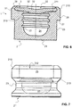
- Figure 6 the closed high-pressure capsule 1 is shown, in which the deformation of the lid 3 is visible.
- the cover 3 protrudes slightly into the receiving space 24 and has clung to the retaining lug 29 along its circumference.
- one or more circumferential grooves 213 can be formed in the inner surface 22 of the crucible 2 ′ which delimits the receiving space 24. These grooves 213 prevent the sample 6 from creeping and thus wetting the support surface 26.
- the crucible 2 ′′ is shown in a third embodiment. Instead of the microstructures 211, it has a specially smooth surface in order to enable cold welding. The surface is preferably lapped.
- FIG Figure 7 A crucible 2 '''according to a fourth embodiment is shown in FIG Figure 7 shown.
- this crucible 2 ''' has a height of approximately 4.0 to 6.0 millimeters, in particular of approximately 4.5 millimeters and a diameter of approximately 5.5 to 8.0 millimeters, in particular of approximately 7.0 millimeters.
- the present crucible 2 ′ has a lower area, the outside diameter of which is smaller than the outside diameter of the upper area.
- These high-pressure capsules 1 enable cold welding with a relatively low pressure.
- the grooves according to the invention prevent wetting of the contact surface of the crucible and enable cold welding and also improve the surface / volume ratio.
- the decomposition reaction of hydrogen peroxide in water and oxygen continued at 38 ° C in the gold-coated capsule, at 67 ° C in the uncoated steel capsule, at 93 ° C in the amorphous carbon-coated capsule and at 98 ° C in the glass ampoule.
- the low decay temperature in the case of the gold-coated high-pressure capsule is due to the catalytic effect of the gold (see Journal of Catalysis, Volume 14, Issue 4, August 1969, pages 355-364 ) in the decomposition reaction of hydrogen peroxide. While an undesirable interaction between the material of the high-pressure capsule and the sample also led to a temperature drop in the high-pressure capsule made of steel (see data sheet hydrogen peroxide from the BG RCI Chemicals Hazardous Substance Information System and CEFIC H 2 O 2 Bulk Storage Guideline, March 2012), the measurement with the high-pressure capsule 1 coated with amorphous carbon, the beginning of the reaction close to the value determined with the glass ampoule was observed. This shows that the high-pressure capsule coated with amorphous carbon has a similarly low impact on the reaction as in the glass ampoule.
- the decomposition energy of hydrogen peroxide is 2888 J / g. For a 31% hydrogen peroxide solution, this results in a decomposition energy of 895 J / g.
- the found values of 948.79 J / g, 865.65 J / g, 818.76 J / g respectively 871.64 J / g for the measurement in the gold-coated, the uncoated, the amorphous carbon-coated high-pressure capsule or the glass ampoule are within the typical spreads for such measurements.
Landscapes
- Chemical & Material Sciences (AREA)
- Engineering & Computer Science (AREA)
- Chemical Kinetics & Catalysis (AREA)
- Materials Engineering (AREA)
- Organic Chemistry (AREA)
- Metallurgy (AREA)
- Mechanical Engineering (AREA)
- Health & Medical Sciences (AREA)
- Physics & Mathematics (AREA)
- Combustion & Propulsion (AREA)
- General Physics & Mathematics (AREA)
- General Chemical & Material Sciences (AREA)
- Pathology (AREA)
- Inorganic Chemistry (AREA)
- Immunology (AREA)
- Analytical Chemistry (AREA)
- Life Sciences & Earth Sciences (AREA)
- Biochemistry (AREA)
- General Health & Medical Sciences (AREA)
- Clinical Laboratory Science (AREA)
- Physical Vapour Deposition (AREA)
- Measuring Fluid Pressure (AREA)
Claims (14)
- Capsule haute pression (1) pour mesures calorimétriques, comprenant:un creuset (2, 2', 2", 2"') qui comprend un espace de réception (24) pour recevoir un échantillon (6),un couvercle (3) pour fermer le creuset (2, 2', 2", 2"'), etau moins dans certaines zones un revêtement (4),dans laquelle le revêtement (4) est disposé au moins dans certaines zones sur une surface (22, 32, 32') de la capsule haute pression (1) tournée vers l'espace de réception (24),caractérisée en ce que le revêtement (4) comprend au moins une couche de carbone amorphe, eten ce que le creuset (2, 2', 2", 2‴) est réalisé en acier.
- Capsule haute pression (1) selon la revendication 1, dans laquelle la couche de carbone amorphe est choisie dans le groupe consistant en une couche de carbone amorphe sans hydrogène, une couche de carbone amorphe tétraédrique sans hydrogène, une couche de carbone amorphe contenant un métal sans hydrogène, une couche de carbone amorphe contenant de l'hydrogène, une couche de carbone amorphe tétraédrique contenant de l'hydrogène, une couche de carbone amorphe contenant un métal contenant de l'hydrogène, et une couche de carbone amorphe modifié contenant de l' hydrogène, et en particulier, une couche de carbone amorphe contenant de l'hydrogène.
- Capsule haute pression (1) selon l'une des revendications précédentes, dans laquelle le revêtement (4) présente une température maximale d'application supérieure à 250°C, notamment d'environ 400°C, et/ou une valeur de micro-dureté supérieure à 1000 HV 0,05, en particulier supérieure à 2500 HV 0,05, et / ou un coefficient de friction contre l'acier à sec dans la plage de 0,02 à 0,3, en particulier de 0,1 à 0,2.
- Capsule haute pression (1) selon l'une des revendications précédentes, dans laquelle le revêtement (4) entoure complètement l'espace de réception (24) dans le cas où le creuset (2, 2', 2", 2‴) est fermé par le couvercle (3).
- Capsule haute pression (1) selon l'une des revendications précédentes, dans laquelle le revêtement (4) est disposé au moins dans certaines zones sur une surface intérieure (22) du creuset (2, 2', 2", 2‴) délimitant l'espace de réception (24),
et/ou dans lequel le revêtement (4) est disposé au moins dans certaines zones sur une surface (32, 32') du couvercle (3), en particulier sur la surface (32) du couvercle (3) tournée vers l'espace de réception (24), lorsque le creuset (2, 2', 2", 2‴) est fermé par le couvercle (3). - Capsule haute pression (1) selon l'une des revendications précédentes, comprenant en outre au moins une couche adhésive, qui se situe entre le revêtement (4) et le creuset (2, 2', 2", 2‴) et/ou entre le revêtement (4) et le couvercle (3), et dans laquelle la couche adhésive comprend une couche de nitrure, en particulier en nitrure de chrome ou une couche de titane.
- Capsule haute pression (1) selon l'une des revendications précédentes, comprenant en outre au moins un revêtement supplémentaire (5), dans laquelle le revêtement supplémentaire (5) comprend au moins un métal, en particulier de l'or, et en particulier est disposé dans une zone de la capsule à haute pression (1) dans laquelle aucun revêtement (4) comprenant l'au moins une couche de carbone amorphe est présente.
- Capsule haute pression (1) selon la revendication 7, dans laquelle un réceptacle (25) pour le couvercle (3) est formé dans une zone supérieure du creuset (2, 2', 2", 2‴), et
dans lequel le revêtement supplémentaire (5) se trouve sur une surface intérieure (22) du creuset (2, 2', 2", 2‴) délimitant le réceptacle (25), et/ou
dans lequel le revêtement supplémentaire (5) se trouve sur une surface circonférentielle (31) du couvercle (3) qui, dans le cas d'un creuset fermé (2, 2', 2", 2‴), est tournée vers la surface intérieure (22 ) du creuset (2, 2', 2", 2‴) délimitant le réceptacle (25). - Capsule haute pression (1) selon l'une des revendications précédentes, dans laquelle le creuset (2, 2', 2", 2‴) et/ou le couvercle (3) comportent au moins un métal, et sont notamment réalisés de l'acier.
- Procédé de fabrication d'une capsule haute pression (1), notamment d'une capsule haute pression selon l'une des revendications précédentes, avec un creuset (2, 2', 2", 2‴) et un couvercle (3) pour fermer le creuset (2, 2', 2", 2‴), le procédé comprenant l'étape consistant à :- revêtir la capsule haute pression (1) au moins dans certaines zones d'un revêtement (4) comprenant au moins une couche de carbone amorphe, dans lequel le revêtement (4) est disposé au moins dans certaines zones sur une surface (22, 32, 32') de la capsule haute pression (1) tournée vers un espace de réception (24), et dans lequel le creuset (2, 2', 2", 2‴) est réalisé en acier.
- Procédé selon la revendication 10, dans lequel le revêtement est réalisé par dépôt de carbone amorphe au moyen d'un dépôt chimique et/ou physique en phase gazeuse, de préférence au moyen d'un dépôt chimique en phase gazeuse assisté par plasma.
- Procédé selon la revendication 11, dans lequel le dépôt a lieu à une température comprise entre 150°C et 300°C, notamment entre 180°C et 250°C.
- Procédé selon l'une des revendications 10 à 12, dans lequel avant de revêtir la capsule haute pression (1) avec l'enrobage (4), au moins une couche adhésive est appliquée par pulvérisation cathodique sur le creuset (2, 2', 2", 2‴) et / ou le couvercle (3), et dans lequel la couche adhésive comprend une couche de nitrure, en particulier du nitrure de chrome ou une couche de titane.
- Procédé selon l'une des revendications 10 à 13, un revêtement supplémentaire (5) comprenant au moins un métal, notamment de l'or, étant appliqué sur le creuset (2, 2', 2", 2‴) et/ou le couvercle (3).
Priority Applications (1)
| Application Number | Priority Date | Filing Date | Title |
|---|---|---|---|
| EP17190525.0A EP3454029B1 (fr) | 2017-09-12 | 2017-09-12 | Capsule haute pression dotée du revêtement |
Applications Claiming Priority (1)
| Application Number | Priority Date | Filing Date | Title |
|---|---|---|---|
| EP17190525.0A EP3454029B1 (fr) | 2017-09-12 | 2017-09-12 | Capsule haute pression dotée du revêtement |
Publications (2)
| Publication Number | Publication Date |
|---|---|
| EP3454029A1 EP3454029A1 (fr) | 2019-03-13 |
| EP3454029B1 true EP3454029B1 (fr) | 2021-08-25 |
Family
ID=60042949
Family Applications (1)
| Application Number | Title | Priority Date | Filing Date |
|---|---|---|---|
| EP17190525.0A Active EP3454029B1 (fr) | 2017-09-12 | 2017-09-12 | Capsule haute pression dotée du revêtement |
Country Status (1)
| Country | Link |
|---|---|
| EP (1) | EP3454029B1 (fr) |
Families Citing this family (2)
| Publication number | Priority date | Publication date | Assignee | Title |
|---|---|---|---|---|
| CN111282608B (zh) * | 2019-11-21 | 2021-09-21 | 中国航空工业集团公司北京长城计量测试技术研究所 | 一种带导流盖的高温共晶点坩埚 |
| CN110954576B (zh) * | 2019-12-11 | 2020-11-13 | 中国科学院力学研究所 | 一种等离子体点火实验装置及方法 |
Citations (1)
| Publication number | Priority date | Publication date | Assignee | Title |
|---|---|---|---|---|
| US20140260955A1 (en) * | 2013-03-13 | 2014-09-18 | Federal-Mogul Corporation | Cylinder liners with adhesive metallic layers and methods of forming the cylinder liners |
Family Cites Families (6)
| Publication number | Priority date | Publication date | Assignee | Title |
|---|---|---|---|---|
| FR2704309B1 (fr) | 1993-04-19 | 1995-06-09 | Quartz Silice Sa | Creuset comportant un revetement protecteur en couche mince, procede de fabrication et applications. |
| DE29504803U1 (de) | 1995-03-21 | 1995-05-18 | IKA-Analysentechnik GmbH, 79423 Heitersheim | Verbrennungsbehälter für Kalorimeter |
| CH695222A5 (de) * | 2001-04-25 | 2006-01-31 | Eva Maria Moser | Gasdichter Behälter. |
| CH696370A5 (de) | 2002-02-20 | 2007-05-15 | Schweizerisches Inst Zur Foerd | Hochdruckkapsel |
| CN102112650A (zh) * | 2008-02-12 | 2011-06-29 | 株式会社iMott | 类金刚石碳膜成膜装置及形成类金刚石碳膜的方法 |
| CH704521A1 (de) * | 2011-02-24 | 2012-08-31 | Swissi Process Safety Gmbh | Probengefäss für kalorimetrische und thermoanalytische Messungen. |
-
2017
- 2017-09-12 EP EP17190525.0A patent/EP3454029B1/fr active Active
Patent Citations (1)
| Publication number | Priority date | Publication date | Assignee | Title |
|---|---|---|---|---|
| US20140260955A1 (en) * | 2013-03-13 | 2014-09-18 | Federal-Mogul Corporation | Cylinder liners with adhesive metallic layers and methods of forming the cylinder liners |
Also Published As
| Publication number | Publication date |
|---|---|
| EP3454029A1 (fr) | 2019-03-13 |
Similar Documents
| Publication | Publication Date | Title |
|---|---|---|
| EP3454029B1 (fr) | Capsule haute pression dotée du revêtement | |
| DE2127162C3 (de) | Schneideinsatz für Schneidwerkzeuge der spanabhebenden Bearbeitung von Stahl Gußeisen und dergleichen Werkstoffe | |
| DE102005057277B4 (de) | Absorberrohr | |
| DE2259569C3 (de) | Kernbrennstoffelement und Verfahren zu dessen Herstellung | |
| EP2682500B1 (fr) | Revêtement sur un outil d'extrusion | |
| DE102010014303A1 (de) | Verbundbauteil und Verfahren zu seiner Herstellung | |
| EP1896627B1 (fr) | Gaine en acier ferritique/martensitique ou austenitique pour combustibles/elements combustibles nucleaires et procede de traitement posterieur d'une couche de protection a base de fecral adaptee a des temperatures elevees appliquee sur celle-ci | |
| EP3379122A1 (fr) | Turbomachine dotée de l'élément de montage | |
| DE3784139T2 (de) | Verfahren zur herstellung eines ueberzugs aus nitriden oder carbonitriden. | |
| EP3907015B1 (fr) | Rouleau de mesure pour déterminer une propriété d'un produit en forme de bande guidé sur le rouleau de mesure | |
| DE2306504A1 (de) | Beschichteter sinterhartmetallkoerper und verfahren zu seiner herstellung | |
| EP3393633A1 (fr) | Ensemble membrane comprenant une couche de liaison | |
| EP2751457A2 (fr) | Raccord de conduit de transport | |
| DE2506112C2 (de) | Verfahren zur Bildung harter Oberflächen auf Kohlenstoffstahl | |
| DE102013209863A1 (de) | Beschichtetes Bauteil | |
| DE1439763A1 (de) | Verfahren zur Herstellung eines Kernreaktorbrennelements | |
| DE2259570B2 (de) | Kernbrennstoffelement sowie Verfahren zu dessen Herstellung | |
| EP0152587B1 (fr) | Appariement des matériaux pour pièces fortement sollicitées | |
| DE10114173A1 (de) | Reaktor | |
| DE69306466T2 (de) | Gegen Korrosion resistentes Rohr | |
| EP3578961B1 (fr) | Dispositif de mesure et procédé d'analyse thermique d'un échantillon | |
| DE102020129089A1 (de) | Energiespeicherzelle, Energiespeicher sowie Verfahren zum Herstellen einer Energiespeicherzelle | |
| WO2001044538A9 (fr) | Dispositif permettant de produire un melange gazeux | |
| DE3107217C2 (de) | Hochtemperaturbeständige verschleißfeste Werkstücke und Verfahren zu ihrer Herstellung | |
| AT502526B1 (de) | Verfahren zur herstellung von schneidplatten mit färbiger oberfläche |
Legal Events
| Date | Code | Title | Description |
|---|---|---|---|
| PUAI | Public reference made under article 153(3) epc to a published international application that has entered the european phase |
Free format text: ORIGINAL CODE: 0009012 |
|
| STAA | Information on the status of an ep patent application or granted ep patent |
Free format text: STATUS: THE APPLICATION HAS BEEN PUBLISHED |
|
| AK | Designated contracting states |
Kind code of ref document: A1 Designated state(s): AL AT BE BG CH CY CZ DE DK EE ES FI FR GB GR HR HU IE IS IT LI LT LU LV MC MK MT NL NO PL PT RO RS SE SI SK SM TR |
|
| AX | Request for extension of the european patent |
Extension state: BA ME |
|
| STAA | Information on the status of an ep patent application or granted ep patent |
Free format text: STATUS: REQUEST FOR EXAMINATION WAS MADE |
|
| RBV | Designated contracting states (corrected) |
Designated state(s): AL AT BE BG CH CY CZ DE DK EE ES FI FR GB GR HR HU IE IS IT LI LT LU LV MC MK MT NL NO PL PT RO RS SE SI SK SM TR |
|
| 17P | Request for examination filed |
Effective date: 20190509 |
|
| STAA | Information on the status of an ep patent application or granted ep patent |
Free format text: STATUS: EXAMINATION IS IN PROGRESS |
|
| 17Q | First examination report despatched |
Effective date: 20201002 |
|
| STAA | Information on the status of an ep patent application or granted ep patent |
Free format text: STATUS: EXAMINATION IS IN PROGRESS |
|
| GRAP | Despatch of communication of intention to grant a patent |
Free format text: ORIGINAL CODE: EPIDOSNIGR1 |
|
| STAA | Information on the status of an ep patent application or granted ep patent |
Free format text: STATUS: GRANT OF PATENT IS INTENDED |
|
| INTG | Intention to grant announced |
Effective date: 20210331 |
|
| GRAS | Grant fee paid |
Free format text: ORIGINAL CODE: EPIDOSNIGR3 |
|
| GRAA | (expected) grant |
Free format text: ORIGINAL CODE: 0009210 |
|
| STAA | Information on the status of an ep patent application or granted ep patent |
Free format text: STATUS: THE PATENT HAS BEEN GRANTED |
|
| AK | Designated contracting states |
Kind code of ref document: B1 Designated state(s): AL AT BE BG CH CY CZ DE DK EE ES FI FR GB GR HR HU IE IS IT LI LT LU LV MC MK MT NL NO PL PT RO RS SE SI SK SM TR |
|
| REG | Reference to a national code |
Ref country code: CH Ref legal event code: EP |
|
| REG | Reference to a national code |
Ref country code: IE Ref legal event code: FG4D Free format text: LANGUAGE OF EP DOCUMENT: GERMAN Ref country code: AT Ref legal event code: REF Ref document number: 1424265 Country of ref document: AT Kind code of ref document: T Effective date: 20210915 |
|
| REG | Reference to a national code |
Ref country code: DE Ref legal event code: R096 Ref document number: 502017011274 Country of ref document: DE |
|
| REG | Reference to a national code |
Ref country code: LT Ref legal event code: MG9D |
|
| REG | Reference to a national code |
Ref country code: NL Ref legal event code: MP Effective date: 20210825 |
|
| PG25 | Lapsed in a contracting state [announced via postgrant information from national office to epo] |
Ref country code: SE Free format text: LAPSE BECAUSE OF FAILURE TO SUBMIT A TRANSLATION OF THE DESCRIPTION OR TO PAY THE FEE WITHIN THE PRESCRIBED TIME-LIMIT Effective date: 20210825 Ref country code: RS Free format text: LAPSE BECAUSE OF FAILURE TO SUBMIT A TRANSLATION OF THE DESCRIPTION OR TO PAY THE FEE WITHIN THE PRESCRIBED TIME-LIMIT Effective date: 20210825 Ref country code: BG Free format text: LAPSE BECAUSE OF FAILURE TO SUBMIT A TRANSLATION OF THE DESCRIPTION OR TO PAY THE FEE WITHIN THE PRESCRIBED TIME-LIMIT Effective date: 20211125 Ref country code: LT Free format text: LAPSE BECAUSE OF FAILURE TO SUBMIT A TRANSLATION OF THE DESCRIPTION OR TO PAY THE FEE WITHIN THE PRESCRIBED TIME-LIMIT Effective date: 20210825 Ref country code: PT Free format text: LAPSE BECAUSE OF FAILURE TO SUBMIT A TRANSLATION OF THE DESCRIPTION OR TO PAY THE FEE WITHIN THE PRESCRIBED TIME-LIMIT Effective date: 20211227 Ref country code: NO Free format text: LAPSE BECAUSE OF FAILURE TO SUBMIT A TRANSLATION OF THE DESCRIPTION OR TO PAY THE FEE WITHIN THE PRESCRIBED TIME-LIMIT Effective date: 20211125 Ref country code: FI Free format text: LAPSE BECAUSE OF FAILURE TO SUBMIT A TRANSLATION OF THE DESCRIPTION OR TO PAY THE FEE WITHIN THE PRESCRIBED TIME-LIMIT Effective date: 20210825 Ref country code: ES Free format text: LAPSE BECAUSE OF FAILURE TO SUBMIT A TRANSLATION OF THE DESCRIPTION OR TO PAY THE FEE WITHIN THE PRESCRIBED TIME-LIMIT Effective date: 20210825 Ref country code: HR Free format text: LAPSE BECAUSE OF FAILURE TO SUBMIT A TRANSLATION OF THE DESCRIPTION OR TO PAY THE FEE WITHIN THE PRESCRIBED TIME-LIMIT Effective date: 20210825 |
|
| PG25 | Lapsed in a contracting state [announced via postgrant information from national office to epo] |
Ref country code: PL Free format text: LAPSE BECAUSE OF FAILURE TO SUBMIT A TRANSLATION OF THE DESCRIPTION OR TO PAY THE FEE WITHIN THE PRESCRIBED TIME-LIMIT Effective date: 20210825 Ref country code: LV Free format text: LAPSE BECAUSE OF FAILURE TO SUBMIT A TRANSLATION OF THE DESCRIPTION OR TO PAY THE FEE WITHIN THE PRESCRIBED TIME-LIMIT Effective date: 20210825 Ref country code: GR Free format text: LAPSE BECAUSE OF FAILURE TO SUBMIT A TRANSLATION OF THE DESCRIPTION OR TO PAY THE FEE WITHIN THE PRESCRIBED TIME-LIMIT Effective date: 20211126 |
|
| PG25 | Lapsed in a contracting state [announced via postgrant information from national office to epo] |
Ref country code: NL Free format text: LAPSE BECAUSE OF FAILURE TO SUBMIT A TRANSLATION OF THE DESCRIPTION OR TO PAY THE FEE WITHIN THE PRESCRIBED TIME-LIMIT Effective date: 20210825 |
|
| PG25 | Lapsed in a contracting state [announced via postgrant information from national office to epo] |
Ref country code: DK Free format text: LAPSE BECAUSE OF FAILURE TO SUBMIT A TRANSLATION OF THE DESCRIPTION OR TO PAY THE FEE WITHIN THE PRESCRIBED TIME-LIMIT Effective date: 20210825 |
|
| REG | Reference to a national code |
Ref country code: BE Ref legal event code: MM Effective date: 20210930 |
|
| REG | Reference to a national code |
Ref country code: DE Ref legal event code: R097 Ref document number: 502017011274 Country of ref document: DE |
|
| PG25 | Lapsed in a contracting state [announced via postgrant information from national office to epo] |
Ref country code: SM Free format text: LAPSE BECAUSE OF FAILURE TO SUBMIT A TRANSLATION OF THE DESCRIPTION OR TO PAY THE FEE WITHIN THE PRESCRIBED TIME-LIMIT Effective date: 20210825 Ref country code: SK Free format text: LAPSE BECAUSE OF FAILURE TO SUBMIT A TRANSLATION OF THE DESCRIPTION OR TO PAY THE FEE WITHIN THE PRESCRIBED TIME-LIMIT Effective date: 20210825 Ref country code: RO Free format text: LAPSE BECAUSE OF FAILURE TO SUBMIT A TRANSLATION OF THE DESCRIPTION OR TO PAY THE FEE WITHIN THE PRESCRIBED TIME-LIMIT Effective date: 20210825 Ref country code: MC Free format text: LAPSE BECAUSE OF FAILURE TO SUBMIT A TRANSLATION OF THE DESCRIPTION OR TO PAY THE FEE WITHIN THE PRESCRIBED TIME-LIMIT Effective date: 20210825 Ref country code: EE Free format text: LAPSE BECAUSE OF FAILURE TO SUBMIT A TRANSLATION OF THE DESCRIPTION OR TO PAY THE FEE WITHIN THE PRESCRIBED TIME-LIMIT Effective date: 20210825 Ref country code: CZ Free format text: LAPSE BECAUSE OF FAILURE TO SUBMIT A TRANSLATION OF THE DESCRIPTION OR TO PAY THE FEE WITHIN THE PRESCRIBED TIME-LIMIT Effective date: 20210825 Ref country code: AL Free format text: LAPSE BECAUSE OF FAILURE TO SUBMIT A TRANSLATION OF THE DESCRIPTION OR TO PAY THE FEE WITHIN THE PRESCRIBED TIME-LIMIT Effective date: 20210825 |
|
| PLBE | No opposition filed within time limit |
Free format text: ORIGINAL CODE: 0009261 |
|
| STAA | Information on the status of an ep patent application or granted ep patent |
Free format text: STATUS: NO OPPOSITION FILED WITHIN TIME LIMIT |
|
| GBPC | Gb: european patent ceased through non-payment of renewal fee |
Effective date: 20211125 |
|
| PG25 | Lapsed in a contracting state [announced via postgrant information from national office to epo] |
Ref country code: LU Free format text: LAPSE BECAUSE OF NON-PAYMENT OF DUE FEES Effective date: 20210912 Ref country code: IT Free format text: LAPSE BECAUSE OF FAILURE TO SUBMIT A TRANSLATION OF THE DESCRIPTION OR TO PAY THE FEE WITHIN THE PRESCRIBED TIME-LIMIT Effective date: 20210825 Ref country code: IE Free format text: LAPSE BECAUSE OF NON-PAYMENT OF DUE FEES Effective date: 20210912 Ref country code: BE Free format text: LAPSE BECAUSE OF NON-PAYMENT OF DUE FEES Effective date: 20210930 |
|
| 26N | No opposition filed |
Effective date: 20220527 |
|
| PG25 | Lapsed in a contracting state [announced via postgrant information from national office to epo] |
Ref country code: SI Free format text: LAPSE BECAUSE OF FAILURE TO SUBMIT A TRANSLATION OF THE DESCRIPTION OR TO PAY THE FEE WITHIN THE PRESCRIBED TIME-LIMIT Effective date: 20210825 |
|
| PG25 | Lapsed in a contracting state [announced via postgrant information from national office to epo] |
Ref country code: GB Free format text: LAPSE BECAUSE OF NON-PAYMENT OF DUE FEES Effective date: 20211125 |
|
| PG25 | Lapsed in a contracting state [announced via postgrant information from national office to epo] |
Ref country code: CY Free format text: LAPSE BECAUSE OF FAILURE TO SUBMIT A TRANSLATION OF THE DESCRIPTION OR TO PAY THE FEE WITHIN THE PRESCRIBED TIME-LIMIT Effective date: 20210825 |
|
| PG25 | Lapsed in a contracting state [announced via postgrant information from national office to epo] |
Ref country code: HU Free format text: LAPSE BECAUSE OF FAILURE TO SUBMIT A TRANSLATION OF THE DESCRIPTION OR TO PAY THE FEE WITHIN THE PRESCRIBED TIME-LIMIT; INVALID AB INITIO Effective date: 20170912 |
|
| PGFP | Annual fee paid to national office [announced via postgrant information from national office to epo] |
Ref country code: AT Payment date: 20230921 Year of fee payment: 7 |
|
| PGFP | Annual fee paid to national office [announced via postgrant information from national office to epo] |
Ref country code: FR Payment date: 20230928 Year of fee payment: 7 Ref country code: DE Payment date: 20230920 Year of fee payment: 7 |
|
| PGFP | Annual fee paid to national office [announced via postgrant information from national office to epo] |
Ref country code: CH Payment date: 20231001 Year of fee payment: 7 |
|
| PG25 | Lapsed in a contracting state [announced via postgrant information from national office to epo] |
Ref country code: MK Free format text: LAPSE BECAUSE OF FAILURE TO SUBMIT A TRANSLATION OF THE DESCRIPTION OR TO PAY THE FEE WITHIN THE PRESCRIBED TIME-LIMIT Effective date: 20210825 |
|
| PG25 | Lapsed in a contracting state [announced via postgrant information from national office to epo] |
Ref country code: TR Free format text: LAPSE BECAUSE OF FAILURE TO SUBMIT A TRANSLATION OF THE DESCRIPTION OR TO PAY THE FEE WITHIN THE PRESCRIBED TIME-LIMIT Effective date: 20210825 |