EP3452989B1 - Systeme und verfahren zur erzeugung von projektionsbildern - Google Patents
Systeme und verfahren zur erzeugung von projektionsbildern Download PDFInfo
- Publication number
- EP3452989B1 EP3452989B1 EP16763126.6A EP16763126A EP3452989B1 EP 3452989 B1 EP3452989 B1 EP 3452989B1 EP 16763126 A EP16763126 A EP 16763126A EP 3452989 B1 EP3452989 B1 EP 3452989B1
- Authority
- EP
- European Patent Office
- Prior art keywords
- voxels
- image
- roi
- subset
- representing
- Prior art date
- Legal status (The legal status is an assumption and is not a legal conclusion. Google has not performed a legal analysis and makes no representation as to the accuracy of the status listed.)
- Active
Links
Images


Classifications
-
- G—PHYSICS
- G06—COMPUTING OR CALCULATING; COUNTING
- G06T—IMAGE DATA PROCESSING OR GENERATION, IN GENERAL
- G06T7/00—Image analysis
- G06T7/0002—Inspection of images, e.g. flaw detection
-
- G06T12/30—
-
- G—PHYSICS
- G06—COMPUTING OR CALCULATING; COUNTING
- G06T—IMAGE DATA PROCESSING OR GENERATION, IN GENERAL
- G06T15/00—3D [Three Dimensional] image rendering
- G06T15/08—Volume rendering
-
- G—PHYSICS
- G06—COMPUTING OR CALCULATING; COUNTING
- G06T—IMAGE DATA PROCESSING OR GENERATION, IN GENERAL
- G06T15/00—3D [Three Dimensional] image rendering
- G06T15/10—Geometric effects
- G06T15/20—Perspective computation
- G06T15/205—Image-based rendering
-
- G—PHYSICS
- G06—COMPUTING OR CALCULATING; COUNTING
- G06T—IMAGE DATA PROCESSING OR GENERATION, IN GENERAL
- G06T19/00—Manipulating 3D models or images for computer graphics
- G06T19/20—Editing of 3D images, e.g. changing shapes or colours, aligning objects or positioning parts
-
- G—PHYSICS
- G06—COMPUTING OR CALCULATING; COUNTING
- G06T—IMAGE DATA PROCESSING OR GENERATION, IN GENERAL
- G06T7/00—Image analysis
- G06T7/0002—Inspection of images, e.g. flaw detection
- G06T7/0004—Industrial image inspection
-
- G—PHYSICS
- G06—COMPUTING OR CALCULATING; COUNTING
- G06T—IMAGE DATA PROCESSING OR GENERATION, IN GENERAL
- G06T7/00—Image analysis
- G06T7/10—Segmentation; Edge detection
- G06T7/11—Region-based segmentation
-
- G—PHYSICS
- G06—COMPUTING OR CALCULATING; COUNTING
- G06F—ELECTRIC DIGITAL DATA PROCESSING
- G06F2203/00—Indexing scheme relating to G06F3/00 - G06F3/048
- G06F2203/048—Indexing scheme relating to G06F3/048
- G06F2203/04808—Several contacts: gestures triggering a specific function, e.g. scrolling, zooming, right-click, when the user establishes several contacts with the surface simultaneously; e.g. using several fingers or a combination of fingers and pen
-
- G—PHYSICS
- G06—COMPUTING OR CALCULATING; COUNTING
- G06F—ELECTRIC DIGITAL DATA PROCESSING
- G06F3/00—Input arrangements for transferring data to be processed into a form capable of being handled by the computer; Output arrangements for transferring data from processing unit to output unit, e.g. interface arrangements
- G06F3/01—Input arrangements or combined input and output arrangements for interaction between user and computer
- G06F3/048—Interaction techniques based on graphical user interfaces [GUI]
- G06F3/0484—Interaction techniques based on graphical user interfaces [GUI] for the control of specific functions or operations, e.g. selecting or manipulating an object, an image or a displayed text element, setting a parameter value or selecting a range
- G06F3/04842—Selection of displayed objects or displayed text elements
-
- G—PHYSICS
- G06—COMPUTING OR CALCULATING; COUNTING
- G06F—ELECTRIC DIGITAL DATA PROCESSING
- G06F3/00—Input arrangements for transferring data to be processed into a form capable of being handled by the computer; Output arrangements for transferring data from processing unit to output unit, e.g. interface arrangements
- G06F3/01—Input arrangements or combined input and output arrangements for interaction between user and computer
- G06F3/048—Interaction techniques based on graphical user interfaces [GUI]
- G06F3/0484—Interaction techniques based on graphical user interfaces [GUI] for the control of specific functions or operations, e.g. selecting or manipulating an object, an image or a displayed text element, setting a parameter value or selecting a range
- G06F3/04845—Interaction techniques based on graphical user interfaces [GUI] for the control of specific functions or operations, e.g. selecting or manipulating an object, an image or a displayed text element, setting a parameter value or selecting a range for image manipulation, e.g. dragging, rotation, expansion or change of colour
-
- G—PHYSICS
- G06—COMPUTING OR CALCULATING; COUNTING
- G06F—ELECTRIC DIGITAL DATA PROCESSING
- G06F3/00—Input arrangements for transferring data to be processed into a form capable of being handled by the computer; Output arrangements for transferring data from processing unit to output unit, e.g. interface arrangements
- G06F3/01—Input arrangements or combined input and output arrangements for interaction between user and computer
- G06F3/048—Interaction techniques based on graphical user interfaces [GUI]
- G06F3/0487—Interaction techniques based on graphical user interfaces [GUI] using specific features provided by the input device, e.g. functions controlled by the rotation of a mouse with dual sensing arrangements, or of the nature of the input device, e.g. tap gestures based on pressure sensed by a digitiser
- G06F3/0488—Interaction techniques based on graphical user interfaces [GUI] using specific features provided by the input device, e.g. functions controlled by the rotation of a mouse with dual sensing arrangements, or of the nature of the input device, e.g. tap gestures based on pressure sensed by a digitiser using a touch-screen or digitiser, e.g. input of commands through traced gestures
- G06F3/04883—Interaction techniques based on graphical user interfaces [GUI] using specific features provided by the input device, e.g. functions controlled by the rotation of a mouse with dual sensing arrangements, or of the nature of the input device, e.g. tap gestures based on pressure sensed by a digitiser using a touch-screen or digitiser, e.g. input of commands through traced gestures for inputting data by handwriting, e.g. gesture or text
-
- G—PHYSICS
- G06—COMPUTING OR CALCULATING; COUNTING
- G06T—IMAGE DATA PROCESSING OR GENERATION, IN GENERAL
- G06T2200/00—Indexing scheme for image data processing or generation, in general
- G06T2200/24—Indexing scheme for image data processing or generation, in general involving graphical user interfaces [GUIs]
-
- G—PHYSICS
- G06—COMPUTING OR CALCULATING; COUNTING
- G06T—IMAGE DATA PROCESSING OR GENERATION, IN GENERAL
- G06T2207/00—Indexing scheme for image analysis or image enhancement
- G06T2207/10—Image acquisition modality
- G06T2207/10028—Range image; Depth image; 3D point clouds
-
- G—PHYSICS
- G06—COMPUTING OR CALCULATING; COUNTING
- G06T—IMAGE DATA PROCESSING OR GENERATION, IN GENERAL
- G06T2207/00—Indexing scheme for image analysis or image enhancement
- G06T2207/10—Image acquisition modality
- G06T2207/10072—Tomographic images
- G06T2207/10081—Computed x-ray tomography [CT]
-
- G—PHYSICS
- G06—COMPUTING OR CALCULATING; COUNTING
- G06T—IMAGE DATA PROCESSING OR GENERATION, IN GENERAL
- G06T2207/00—Indexing scheme for image analysis or image enhancement
- G06T2207/20—Special algorithmic details
- G06T2207/20021—Dividing image into blocks, subimages or windows
-
- G—PHYSICS
- G06—COMPUTING OR CALCULATING; COUNTING
- G06T—IMAGE DATA PROCESSING OR GENERATION, IN GENERAL
- G06T2207/00—Indexing scheme for image analysis or image enhancement
- G06T2207/20—Special algorithmic details
- G06T2207/20092—Interactive image processing based on input by user
- G06T2207/20104—Interactive definition of region of interest [ROI]
-
- G—PHYSICS
- G06—COMPUTING OR CALCULATING; COUNTING
- G06T—IMAGE DATA PROCESSING OR GENERATION, IN GENERAL
- G06T2207/00—Indexing scheme for image analysis or image enhancement
- G06T2207/20—Special algorithmic details
- G06T2207/20212—Image combination
- G06T2207/20216—Image averaging
-
- G—PHYSICS
- G06—COMPUTING OR CALCULATING; COUNTING
- G06T—IMAGE DATA PROCESSING OR GENERATION, IN GENERAL
- G06T2207/00—Indexing scheme for image analysis or image enhancement
- G06T2207/30—Subject of image; Context of image processing
- G06T2207/30108—Industrial image inspection
- G06T2207/30112—Baggage; Luggage; Suitcase
-
- G—PHYSICS
- G06—COMPUTING OR CALCULATING; COUNTING
- G06T—IMAGE DATA PROCESSING OR GENERATION, IN GENERAL
- G06T2210/00—Indexing scheme for image generation or computer graphics
- G06T2210/12—Bounding box
-
- G—PHYSICS
- G06—COMPUTING OR CALCULATING; COUNTING
- G06T—IMAGE DATA PROCESSING OR GENERATION, IN GENERAL
- G06T2219/00—Indexing scheme for manipulating 3D models or images for computer graphics
- G06T2219/20—Indexing scheme for editing of 3D models
- G06T2219/2016—Rotation, translation, scaling
Definitions
- Imaging technologies including x-ray computed tomography, magnetic resonance imaging (MRI), positron emission tomography (PET), and many others have found widespread use in applications as diverse as medical imaging and cargo inspection.
- Imaging techniques involve measuring a property of an object across an array of voxels in three-dimensions.
- x-ray imaging techniques involve aiming a beam of x-ray radiation at the object to be imaged and measuring the intensity of x-rays received through the object. The attenuation of the x-ray beam depends on material properties of the object such as mass density or effective atomic number.
- imaging techniques it is possible to reconstruct a three-dimensional or projected two-dimensional image of the object.
- the three-dimensional volumetric or two-dimensional projection images can be used to detect suspicious or dangerous objects hidden in baggage or cargo, for example, contraband.
- the three-dimensional volumetric or two-dimensional projection images can be used to detect organic or inorganic structures related to disease or injury within a biological organism.
- US 2007/297560 A1 discloses a method and system to analyze the content of a packed bag utilizing a scanner.
- the bag is scanned for a scannable characteristic to acquire scan data representative of a content of the piece of baggage.
- a volumetric data set is generated from the scan data, wherein the volumetric data set includes voxel values of the scannable characteristic throughout a volume of interest in the baggage.
- a rendered view is produced of the content of the piece of baggage based on the voxel values within a selected range from the volumetric data set.
- the method and system also provide identifying a threat by analyzing Hounsfield Units of the material of interest.
- an imaging system according to claim 15.
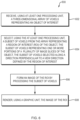
- Systems, methods, and non-transitory computer-readable media taught herein process a subset of a three-dimensional array of voxels to form an image of a region of interest (ROI) in an object.
- ROI region of interest
- Images formed using the systems, methods, and non-transitory computer-readable media taught herein are clear, comprehensible, and contextual. Images formed in accordance with the teachings herein allow a viewer, for example, a medical professional, a security agent, or other, to select a region of interest of an object under examination and have a subset of voxels representing the ROI processed to form an image of the ROI.
- the systems, methods, and computer-readable media can render a two-dimensional image of the selected ROI that is interpretable by the viewer or by an image processing algorithm of a computer.
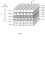
- the systems, methods, and non-transitory computer-readable media taught herein select the subset of voxels that represent the region of interest along a direction perpendicular to a view direction defined by the region of interest.
- the subset of voxels represents one or more portions of a plurality of image slices of the object.
- any three-dimensional array of voxels regardless of the type of x-ray system used to collect the voxel data.
- any three-dimensional array of voxels can be processed as taught herein to produce and render images of improved quality and resolution to facilitate identification of and examination of objects included therein.
- an "object” encompasses a volume that includes a physical mass and space surrounding the physical mass.
- the term “object” is not limited to the bounds of a particular physical object but is to be considered as a volume that may include one or more physical objects, empty space, or both.
- the "object” can include, but is not limited to, an item such as a bag, bin or other container under inspection, items disposed within the bag, bin or other container, portions of the internal volume of a tunnel or scanning region through which the item passes, a human body or any portion thereof, or an animal body and any portion thereof.
- a "region of interest” can be any subset of voxels that is to be imaged from a three-dimensional array of voxels representative of the object.
- the term "region of interest” can include one or more items or one or more objects, empty space, or both, and is not limited to a location within an object that includes an item such as contraband or a portion of a skeletal system.
- the region of interest can be identified by a user using an interactive user element of a computing system or can be identified based on implementation of a computer-implemented method.
- a "slice” or an "image slice” of the three-dimensional array of voxels can be a plurality of voxels having the same coordinate value along a coordinate axis ( e.g. , the same x-value, y-value, or z-value) of the three-dimensional array of voxels.
- the "slice” or an "image slice” can correspond to voxels of the three-dimensional array of voxels that lie in a plane along a coordinate axis of the three-dimensional array of voxels.
- a three-dimensional volumetric representation of an object is generated including a plurality of voxels.
- the plurality of voxels includes data representative of a physical property of the object such as density, effective atomic number, or electron spin relaxation times.
- the plurality of voxels can be visualized volumetrically or by projecting the data into two-dimensions.
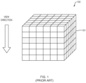
- Methods of generating the two-dimensional projection image include collapsing the entire three-dimensional array of voxels along an axis representing a view direction or selecting a single slice of the three-dimensional array of voxels that includes some or all of the voxels that have the same value along the axis representing the view direction (i.e., an x-axis, y-axis, z-axis, or any other direction with respect to a coordinate system of the volume).
- An image produced by collapsing the entire three-dimensional array of voxels includes features that a human or machine viewer can intuitively recognize and understand. However, collapsing the entire three-dimensional array of voxels produces a cluttered image wherein features at different depths along the view direction overlap and become largely indistinguishable in the projection image.
- a single slice provides a cleaner image wherein the pixels correspond directly to individual physical measurements of a property of the object.
- single slice images are highly unintuitive to human and machine viewers because no additional context is provided to help the viewer identify what is shown in the image.
- users of imaging systems that provide single slice images require extensive training to understand how to interpret the visual information provided in a single-slice image.
- viewing a full object using single slices is very time-consuming due to the large number of image slices in an object. In contexts such as the security context where high throughput is essential, an unacceptable amount of time may be needed to step through single slices of the object.
- an ROI image as taught herein from a subset of voxels in an array of voxels is not dependent on the type or configuration of the system that collected the measurement data from which the array of voxels is derived.
- Applicable systems can include medical systems, cargo scanning systems, or any other imaging modality that generates a three-dimensional array representation of an object.
- the concepts taught herein to select and render an image of an ROI of an object can be applied across known systems with little or no change to the detectors and radiation sources. A range of exemplary systems will now be described that are compatible with teachings presented herein.
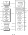
- Fig. 14 illustrates an exemplary imaging system 1000 for forming and rendering projection images of at least a portion of an object 130, according to one embodiment of the present disclosure.
- the imaging system 1000 includes an imaging chamber 110, a transport system 120 to transport the object 130, a computing device 140, an x-ray source 150, and a detector 160.
- the imaging chamber encloses a passageway 122.
- the computing device 140 can include a display 142, an input device 144, a processing unit 145, and a graphic unit 146.
- the computing device 140 can be used to render images of one or more ROIs as taught herein, the GUI 710, and other interfaces on the display 142 using the graphic unit 146.
- the detector 160 is disposed relative to the x-ray source 150 to detect the measurement data along the scan path 105.
- the source 150 and detector 160 can have a fixed spatial relationship and may rotate about a longitudinal axis of the imaging system 1000 as, for example, on a gantry.
- one or more sources 150 and detectors 160 can be fixed with respect to the transport system 120.
- the positions of the x-ray source 150 and detector 160 can be fully known as a function of time during scanning of the object 130.
- the computing device 140 includes at least one processing unit 145 including at least one central processing unit (CPU).
- the computing device 140 can be configured to receive measurement data acquired by the detector 160.
- the processing unit 145 is programmable to execute processor-executable instructions such as image processing executable code to form projection images of portions of the object 130 as described in greater detail above.
- the central processing unit is programmable to compute a reconstructed three-dimensional array of voxels representative of the object 130 by applying at least one iteration of an iterative reconstruction to the measurement data to derive the reconstructed three-dimensional array of voxels.
- the programmable processing unit can execute image processing code 1127 to receive the three-dimensional array of voxels representing the object upon execution of processor-executable instructions. Execution of the image processing code 1127 allows a user to select an ROI of the object from a projection image. Based on the selected ROI, the image processing code 1127 selects a subset of voxels from the array of voxels representative of the selected ROI.
- the subset of voxels represents one or more portions of a plurality of image slices of the object and is selected along a direction perpendicular to a view direction defined by the ROI. Execution of the image processing code 1127 can form an image of the ROI by processing the subset of voxels.
- the computing device 140 and the processing unit 145 are discussed in greater detail with respect to Fig. 13 .
- the graphic unit 146 can be configured to render an image of an ROI, for example, ROI image 902 from the three-dimensional array of voxels 200, 300, 400, 500 on the display 142.
- the graphic unit 146 can render a user interface on the display 142 to allow a user of the imaging system 1000 to interact with the user interface of the computing device 140 with an input device 144.
- the user interface is a GUI 710 as described, for example, in relation to Figs. 8 and 9 .
- the input device 144 can be a keyboard, a mouse, a trackball, a touchpad, a stylus, a touchscreen of the display 142 or any other suitable device that allows a user to interface with the computing device.
- the GUI 400 can be rendered on a touchscreen to allow a user to input information or data via the touchscreen.
- the imaging chamber 110 may be made of appropriate metal or plastic materials that allow the desired spacing and orientation of the x-ray source 150 and the detector 160 relative to the object 130.
- the imaging chamber 110 may include radiation stopping or absorbing material such as lead.
- the imaging chamber 110 can house one or more x-ray sources 150 and detectors 160.
- the x-ray source 150 may be an x-ray source or a gamma ray source.
- the x-ray source(s) 150 can be configured to emit a cone-beam of radiation to interact with the object 130, and the detectors 160 can be configured to detect radiation indicative of an interaction of the radiation with any portion of the object.
- the detector 160 can detect attenuated radiation that has passed through a portion of the object 130.
- the x-ray source 150 and detector 160 can move cooperatively along a circular scan path that may be defined relative to the motion of an object 130 to form a helical cone beam.
- the scan path may be a partial or complete circle of constant radius where the object 130 travels along a line passing through a central portion of the circle.
- the x-ray source 150 of some embodiments can include a high-energy electron beam and an extended target or array of targets.
- imaging systems as taught herein can have more than one source and detector.
- the detector 160 may be configured with multiple detector elements in a detector array.
- the processing unit 145 can be configured to generate the three-dimensional array of voxels representing the object from the radiation detected by the detectors 160 using any suitable image reconstruction methodology.
- Examples of direct reconstruction techniques that may be used to reconstruct the three-dimensional array of voxels in some embodiments include a filtered back-projection methodology, an analytical cone-beam methodology, an approximate cone-beam methodology, a Fourier reconstruction methodology, an extended parallel back-projection methodology, a filtered back-projection with dynamic pitch methodology, a pi-line-based image reconstruction methodology, a Feldkamp-type reconstruction methodology, a tilted-plane Feldkamp-type reconstruction methodology, or any other direct reconstruction technique that meets application-specific requirements.
- Iterative reconstruction techniques may also be employed in the system 1000 to reconstruct the three-dimensional array of voxels representing the object.
- iterative reconstruction techniques include a simultaneous algebraic reconstruction technique (SART), a simultaneous iterative reconstruction technique (SIRT), an ordered subset convex technique (OSC), ordered subset maximum likelihood methodologies, an ordered subset expectation maximization (OSEM) methodology, an adaptive statistical iterative reconstruction technique (ASIR) methodology, a least squares QR methodology, an expectation maximization (EM) methodology, an OS-separable paraboloidal surrogates technique (OS-SPS), an algebraic reconstruction technique (ART), a Kacsmarz reconstruction technique, or any other iterative reconstruction technique or methodology that meets application-specific requirements.
- a sparse matrix or a compressed sensing technique can be used to increase the speed of the reconstruction.
- an initial state is defined before successive iterative steps are performed.
- an iterative reconstruction technique may perform many iterations before achieving convergence. Each iteration step is computationally intensive, so conducting many iteration steps can unacceptably increase the total time for data reconstruction. Reducing the numbers of iterations to achieve a solution can greatly increase the speed and efficiency of the image reconstruction computation.
- the process of iterative reconstruction can be initialized using the output from a direct reconstruction technique including, but not limited to, a filtered back-projection methodology. The use of output from a direct reconstruction technique can significantly reduce the number of iterations to reach convergence and speed up total processing time.
- radiation at two different energy levels may be directed such that they pass through a portion of the object 130.
- the ratio of the attenuation between beams at two different energy levels can provide information about the atomic number or elemental composition of the portion of the object 130.
- the system 1000 may be configured to compute data in the three-dimensional array of voxels corresponding to the density, or atomic number, or both density and atomic number properties, of a portion of the volume of the object 130.
- measurement data or reconstructed images or representations may be stored and retrieved for analysis at a later date or may be displayed to a user on the display 142.
- the measurement data collected at the detector 150 may be interpolated onto a virtual array or interpolation may be used to modify or replace data values associated with malfunctioning or missing detector positions.
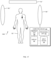
- Figs. 15-17 depict systems for acquiring measurement data of the object and generating images of ROIs of the object in accordance with the teachings herein.
- the object 130' can be a biological organism.
- the systems of Figs. 15-17 can generate and process measurement data to create three-dimensional volumetric or two-dimensional projection images of an ROI included in the object 130'.
- the ROI can include an organic or inorganic structure within the biological organism.
- Fig. 15 depicts a system 1000' that includes a source 150', a detector 160', and the computing device 140.
- the computing device can include the graphic unit 146, the processing unit 145, the display 142, and the input device 144.
- the source 150' can emit radiation that can interact with the object 130' and then be detected by the detector 160'.
- the detector 160' can generate measurement data based on the received radiation that is indicative of the interaction of the radiation with the object 130'.
- the source 150' can be an x-ray source similar to the system described above with reference to Fig. 14 .
- the source 150' can be the x-ray source of a medical computed tomography (CT) system.
- CT computed tomography
- the source 150' can emit other forms of penetrating or non-penetrating radiation such as gamma rays, microwave radiation, infrared radiation, visible radiation, ultraviolet radiation, or any other suitable form of radiation.
- the source 150' can be configured to emit a cone-beam of radiation to interact with the object 130', and the detector(s) 160' can be configured to detect radiation indicative of an interaction of the radiation with any portion of the object.
- the detector 160' can detect attenuated radiation that has passed through a portion of the object 130'.
- the source 150' and detector 160' can move cooperatively along a circular scan path that may be defined relative to the motion of an object 130' to form a helical cone beam.
- the scan path may be a partial or complete circle of constant radius where the object 130' travels along a line passing through a central portion of the circle.
- the x-ray source 150' of some embodiments can include a high-energy electron beam and an extended target or array of targets.
- imaging systems as taught herein can have more than one source and detector.
- the detector 160' may be configured with multiple detector elements in a detector array. In some embodiments, the detector 160' can be configured to detect radiation backscattered or reflected from the object 130' rather than radiation transmitted through the object 130'.
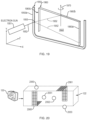
- Fig. 16 depicts a system 1000" including a source 150", a detector 160", and the computing device 140.
- the computing device can include the graphic unit 146, the processing unit 145, the display 142, and the input device 144.
- the source 150" can be located within the object 130".
- the source 150" can be configured to emit a variety of fundamental particles and waves including alpha particles, beta particles, gamma particles, positrons, muons, electrons, or photons from within the object 130".
- the source 150" can emit a first particle or wave that can convert into a second particle or wave that is then detected by the detector 160".
- the source 150" can include radionuclides that emit positrons as in positron emission tomography. The positrons can recombine with electrons to release gamma rays that are then detected by the detector 160".
- the source 150" can emit light that is converted by interaction with the object 130" into an acoustic signal as in photo- or optoacoustic imaging.
- the detectors 160" in this embodiment can be ultrasonic transducers that receive the acoustic signal to produce measurement data.
- the detector 160" may be configured with multiple detector elements in a detector array. In some embodiments, multiple detectors 160" in an array can be placed around the object 130" to receive particles or waves emitted directly or indirectly by the source 150" within the object 130". In some embodiments, the computing device 140 can use techniques such as time-of-flight to determine a position of the source 150" within the object 130" based on measurement data received at different times by the detectors 160" in the detector array.
- Fig. 17 depicts a system 1000'" including a source 150"', a detector 160"', and the computing device 140.
- the computing device can include the graphic unit 146, the processing unit 145, the display 142, and the input device 144.
- the source 150′′′ can stimulate or perturb a portion of the object 130′′′ in a way that can be detected by the detector 160′′′.
- the source 150′′′ can be an electromagnet or permanent magnet.
- the source 150′′′ can operate to stimulate or perturb all or a portion of the object 130′′′ by applying a large magnetic field to the object to excite or align the nuclear spins of constituent components of the object 130′′′ such as hydrogen atoms.
- the source 150′′′ can apply a magnetic field that varies in space and time in some embodiments.
- the detector 160′′′ may be configured with multiple detector elements in a detector array.
- the detector 160′′′ can include magnetic coils that can detect radio frequency signals emitted by excited constituents of the object 130′′′ such as hydrogen atoms.
- the computing device 140 can control the operation of the source 150′′′ and detector 160′′′ to correlate measurement data with spatial locations within or around the object 130′′′.
- the source and detector of systems to generate measurement data can have a number of relationships.
- the source and detector can have a fixed spatial relationship and, for example, may rotate about a longitudinal axis of the imaging system as, for example, on a gantry.
- one or more sources and detectors can be fixed in space or relative to the motion of an object during imaging.
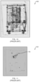
- FIG. 18A and 18B An example rotating gantry according to various embodiments is depicted in Figs. 18A and 18B .
- the gantry 1840 includes an opening or central bore 1845 through which objects may pass in connection with a transport system as discussed above with reference to Fig. 14 .
- the x-ray source 1850 may be located on the gantry 1840, and the detector array 1860 may be located substantially opposite the x-ray source 1850 across the opening.
- a coating such as a metal foil 1841, 1842, 1843 can be overlaid on one or more elements of the detector array 1860.
- the coated elements 1841, 1842, 1843 may be sensitive to different radiation energy than the exposed elements.
- embodiments taught herein may be capable of measuring volume properties such as atomic number or elemental composition.
- the introduction of secondary energy detector elements can leave gaps in the dataset when performing a volumetric data reconstruction for a property that requires low energy radiation such as density.
- the gaps in the volumetric data may be filled by interpolation of neighboring values, averaging, or by any other suitable method.
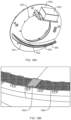
- FIG. 19 illustrates an x-ray source target 1950 and a detector array 1960 geometry and relationship according to some embodiments.
- the x-ray source target 1950 is activated by a high-energy electron beam 1952 from an electron source 1951.
- an e-beam 1952 can be directed to impinge on target 1950, which responds by emitting x-rays in 4 ⁇ directions.
- Collimators (not shown) may be used to form the emitted radiation into a fan beam, cone beam, pencil beam, or other shaped beam as dictated by application-specific requirements.
- the shaped beam of radiation enters an examination region 1922 through which an object passes.
- a detector array 1960 may be located diametrically opposite to the radiation emission point and can respond to the attenuated beam of radiation.
- the detectors along arms 1960a and 1960b of the detector array 1960 detect x-rays in the fan beam generated along arm 1950a, for example, fan beam 1952 emitted by x-ray source location 1955.
- the plane defined by the detector array can be rotated by an angle 1970 with respect to the plane defined by the x-ray source target 1950. Rotation by an angle 1970 can help to avoid a situation in which x-rays emitted from the x-ray source target 1950 are blocked by an arm of the detector array before passing through the examination region 1922. For example, radiation emitted at location 1955 will be blocked on the outer surface of detector arm 1960c if the rotation angle 1970 is zero.
- the electron beam 1952 can be steered to control and sweep the x-ray source target 1950 including location 1955.
- the scanning electron beam 1952 can be further configured to irradiate some or all of the targetable elements.
- a multitude of targetable elements may be disposed at angles along a trajectory of at least 180° about the direction of transport of an object.
- the x-ray source target 1950 and detector array 1960 are suitable for use in the imaging system 1000.
- the beam of electrons 1952 from the electron source 1951 is swept across the surface of the x-ray source target 1950 to cause emission of x-rays over an angular range of less than 180° or at least 180° about the direction of transport of the object 130.
- the speed of transport of an object relative to the scanning speed of the electron beam to cause emission of x-rays from the x-ray source target 1950 is controlled to provide an imaging modality with a pitch approximately equal to 1 or greater than 1.
- FIG. 20 illustrates an example x-ray source and detector geometry according to some embodiments taught herein.
- the x-ray source and detector are both fixed in location and do not rotate.
- a detector array 2060 may have multiple segments that form an L-shape or staple shape to cover a greater complement of angles around an object 130.
- multiple detectors 2060, 2061 can be included within a single system at different locations along the tunnel 122 traversed by the object 130.
- An exemplary system using fixed (i.e., non-rotating or moving) x-ray sources and detectors may include multiple x-ray sources 2050, 2051, 2052, 2053 that each emit radiation beams toward detectors 2060, 2061.
- the x-ray sources 2050, 2051, 2052, 2053 can be controlled such that only one x-ray source emits toward a given detector at any point in time so that the received measurement data can be properly associated with the correct x-ray source.
- Multiple x-ray sources 2050, 2051, 2052, 2053 may be skewed such that the range of angles between a given x-ray source and detector array is not duplicated by another x-ray source and detector combination. It will be apparent to one skilled in the art that any number of x-ray sources and detector arrays could be disposed within an imaging system to achieve any total angular coverage dictated by the specifics of the application.
- the x-ray sources 2050, 2051, 2052, 2053 and detectors 2060, 2061 are suitable for use in the imaging system 1000.
- the x-ray sources 2050, 2051, 2052, 2053 are controlled to emit and the detectors 2060, 2061 are controlled to receive x-rays over a range of angles of less than 180° or at least 180° about the direction of transport of the object 130.
- the speed of transport of an object relative to the speed of the sequence of x-ray emission and detection is controlled to provide an imaging modality with a pitch approximately equal to 1 or greater than 1.
Landscapes
- Engineering & Computer Science (AREA)
- Physics & Mathematics (AREA)
- Theoretical Computer Science (AREA)
- General Physics & Mathematics (AREA)
- Computer Vision & Pattern Recognition (AREA)
- Computer Graphics (AREA)
- Quality & Reliability (AREA)
- Computer Hardware Design (AREA)
- Geometry (AREA)
- Architecture (AREA)
- Computing Systems (AREA)
- General Engineering & Computer Science (AREA)
- Software Systems (AREA)
- Apparatus For Radiation Diagnosis (AREA)
- Image Generation (AREA)
- Analysing Materials By The Use Of Radiation (AREA)
- Geophysics And Detection Of Objects (AREA)
- Magnetic Resonance Imaging Apparatus (AREA)
- Nuclear Medicine (AREA)
- Image Processing (AREA)
Claims (14)
- Verfahren zum Bilden eines Bilds eines Objekts, umfassend:Empfangen, unter Verwendung mindestens einer konfigurierbaren oder programmierbaren Verarbeitungseinheit (145), einer dreidimensionalen Anordnung von Voxeln (200, 300, 400, 500), die ein physisches Objekt (130) darstellen, wobei die dreidimensionale Anordnung von Voxeln Daten beinhaltet, die repräsentativ für eine physikalische Eigenschaft des Objekts sind;Auswählen, unter Verwendung der mindestens einen konfigurierbaren oder programmierbaren Verarbeitungseinheit, einer Untergruppe von Voxeln (230a-230c, 330a-330c, 430a-430c, 530a-530c) aus der Anordnung von Voxeln, die eine Region von Interesse, ROI, des Objekts darstellen, wobei die Untergruppe von Voxeln einen oder mehrere Abschnitte einer Vielzahl von Bildschichten (202a-202f, 302a-302f, 402a-402f) des Objekts darstellt, die Untergruppe von Voxeln, die entlang einer Richtung senkrecht zu einer Achse ausgewählt werden, eine für die ROI spezifische Blickrichtung (45) darstellt; undBilden eines Bilds der ROI durch Summieren von Massendichtewerten des Objekts, das in der Untergruppe von Voxeln entlang der Blickrichtung beinhaltet ist, wobei das Bild eine geschätzte Gesamtmasse des Objekts in der ROI entlang der Blickrichtung darstellt.
- Verfahren nach Anspruch 1, ferner umfassend ein Rendern, unter Verwendung einer Grafikeinheit (146), des Bilds der ROI.
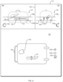
- Verfahren nach Anspruch 1, ferner umfassend ein Verarbeiten des Bilds der ROI unter Verwendung einer Rechenvorrichtung mit einem Erkennungsalgorithmus, um einen Schmuggelartikel (750) innerhalb des Objekts zu erkennen.
- Verfahren nach Anspruch 1, wobei ein Bilden des Bilds der ROI Folgendes beinhaltet:Summieren von Massendichtewerten des Objekts, das aus der Untergruppe von Voxeln entlang der Blickrichtung ausgeschlossen wurde, um einen ersten zweidimensionalen Datensatz (515) zu erstellen;Summieren von Massendichtewerten des Objekts von allen Voxeln entlang der Blickrichtung, um einen zweiten zweidimensionalen Datensatz (550) zu erstellen; undSubtrahieren des ersten zweidimensionalen Datensatzes von dem zweiten zweidimensionalen Datensatz.
- Verfahren nach Anspruch 1, wobei ein Bilden des Bilds der ROI Folgendes beinhaltet:Summieren von Massendichtewerten des Objekts, das aus der Untergruppe von Voxeln entlang der Blickrichtung ausgeschlossen wurde, um einen ersten zweidimensionalen Datensatz (515) zu erstellen;Empfangen eines zweiten zweidimensionalen Datensatzes (550), der aus Messdaten erzeugt wird, die unter Verwendung einer Zeilenscan-Bildgebungstechnik oder aus einem Vollprojektionsbild entlang der Blickrichtung (45), das die gesamte dreidimensionale Anordnung von Voxeln enthält, erlangt werden;Subtrahieren des ersten zweidimensionalen Datensatzes von dem zweiten zweidimensionalen Datensatz.
- Verfahren nach Anspruch 4, ferner umfassend ein erneutes Abtasten der dreidimensionalen Anordnung von Voxeln von einem orthografischen Koordinatensystem in ein perspektivisches Koordinatensystem, das mit der Blickrichtung ausgerichtet ist.
- Verfahren nach Anspruch 1, wobei die Vielzahl von Bildschichten (202a-202f) des Objekts alle zusammenhängend sind.
- Verfahren nach Anspruch 1, wobei die Untergruppe von Voxeln eine erste Untergruppe von Voxeln (230a, 330a, 430a, 530a) ist und die ROI eine erste ROI (510) ist, das Verfahren ferner umfassend:Auswählen, unter Verwendung der mindestens einen Verarbeitungseinheit, einer zweiten Untergruppe von Voxeln (230b, 330b, 430b, 530b) aus der Anordnung von Voxeln, die eine zweite Region von Interesse, ROI, (512) des Objekts darstellen, wobei die zweite Untergruppe von Voxeln einen oder mehrere Abschnitte einer zweiten Vielzahl von Bildschichten des Objekts darstellt, die zweite Untergruppe von Voxeln, die entlang einer Richtung senkrecht zu einer zweiten Achse ausgewählt werden, eine zweite, für die zweite ROI spezifische Blickrichtung darstellt; undBilden eines Bilds der zweiten ROI durch Summieren von Massendichtewerten des Objekts, das in der zweiten Untergruppe von Voxeln entlang der zweiten Blickrichtung beinhaltet ist, wobei das Bild der zweiten ROI eine geschätzte Gesamtmasse des Objekts in der zweiten ROI entlang der Blickrichtung darstellt.
- Verfahren nach Anspruch 8, wobei mindestens ein Voxel der ersten Untergruppe von Voxeln (430a) auch in der zweiten Untergruppe von Voxeln (430b) beinhaltet ist.
- Verfahren nach Anspruch 1, ferner umfassend ein Drehen von Koordinatenachsen der dreidimensionalen Anordnung von Voxeln, um sie mit der Blickrichtung auszurichten.
- Verfahren nach Anspruch 1, ferner umfassend:Bestimmen einer Bildschicht, die einen Rand des Objekts bezeichnet; undAusschließen von Voxeln jenseits dieser Schicht aus der Untergruppe von Voxeln.
- Verfahren nach Anspruch 1, ferner umfassend:Empfangen einer markierten Region innerhalb des Bilds der ROI, die einem Artikel von Interesse entspricht; undRendern, unter Verwendung einer Grafikeinheit (146), eines Bilds der markierten Region.
- Verfahren nach Anspruch 12, wobei die markierte Region von einem Benutzer durch Ziehen eines Begrenzungsrahmens (752) identifiziert wird, um die markierte Region zu definieren.
- Bildgebungssystem (1000), umfassend:eine Bildgebungsgerät zum Erfassen von Messdaten eines Objekts; undeine konfigurierbare oder programmierbare Verarbeitungseinheit (145), die kommunikativ mit einem Speicher (1106) gekoppelt ist, wobei die konfigurierbare oder programmierbare Verarbeitungseinheit bei Ausführung von prozessorausführbaren Befehlen betrieben wird, um das Verfahren nach einem der Ansprüche 1-13 durchzuführen.
Applications Claiming Priority (2)
| Application Number | Priority Date | Filing Date | Title |
|---|---|---|---|
| US201662332859P | 2016-05-06 | 2016-05-06 | |
| PCT/US2016/047562 WO2017192160A1 (en) | 2016-05-06 | 2016-08-18 | Systems and methods for generating projection images |
Publications (2)
| Publication Number | Publication Date |
|---|---|
| EP3452989A1 EP3452989A1 (de) | 2019-03-13 |
| EP3452989B1 true EP3452989B1 (de) | 2025-07-09 |
Family
ID=56889202
Family Applications (1)
| Application Number | Title | Priority Date | Filing Date |
|---|---|---|---|
| EP16763126.6A Active EP3452989B1 (de) | 2016-05-06 | 2016-08-18 | Systeme und verfahren zur erzeugung von projektionsbildern |
Country Status (8)
| Country | Link |
|---|---|
| US (1) | US10380727B2 (de) |
| EP (1) | EP3452989B1 (de) |
| JP (1) | JP6968826B2 (de) |
| AU (1) | AU2016405571B2 (de) |
| CA (1) | CA3022215C (de) |
| ES (1) | ES3039891T3 (de) |
| MA (1) | MA44842A (de) |
| WO (1) | WO2017192160A1 (de) |
Families Citing this family (14)
| Publication number | Priority date | Publication date | Assignee | Title |
|---|---|---|---|---|
| US10586400B2 (en) * | 2018-02-23 | 2020-03-10 | Robert E Douglas | Processing 3D medical images to enhance visualization |
| WO2017200527A1 (en) * | 2016-05-16 | 2017-11-23 | Hewlett-Packard Development Company, L.P. | Generating a shape profile for a 3d object |
| US10692251B2 (en) * | 2017-01-13 | 2020-06-23 | Canon Medical Systems Corporation | Efficient variance-reduced method and apparatus for model-based iterative CT image reconstruction |
| US10089758B1 (en) * | 2017-03-29 | 2018-10-02 | Carestream Health, Inc. | Volume image reconstruction using projection decomposition |
| WO2018186758A1 (en) | 2017-04-07 | 2018-10-11 | Auckland Uniservices Limited | System for transmitting and viewing a series of images |
| JP7280464B2 (ja) * | 2018-11-13 | 2023-05-24 | 国立研究開発法人国立循環器病研究センター | プラナー画像生成装置 |
| US12443652B2 (en) * | 2019-06-03 | 2025-10-14 | Zebra Technologies Corporation | Method, system and apparatus for detecting product facings |
| CN112446227B (zh) * | 2019-08-12 | 2025-02-25 | 浙江菜鸟供应链管理有限公司 | 物体检测方法、装置及设备 |
| US11107445B2 (en) * | 2019-09-13 | 2021-08-31 | Canon Medical Systems Corporation | Network centric windowing system for integration and display of visual data from networked sources |
| WO2021186957A1 (ja) * | 2020-03-18 | 2021-09-23 | 富士フイルム株式会社 | 画像処理装置、方法およびプログラム |
| CN113643360B (zh) * | 2020-05-11 | 2024-12-27 | 同方威视技术股份有限公司 | 目标物体定位方法、装置、设备、介质和程序产品 |
| JP7451748B2 (ja) * | 2020-09-29 | 2024-03-18 | 富士フイルム株式会社 | 画像処理装置、画像処理装置の作動方法、画像処理装置の作動プログラム |
| KR20220086896A (ko) * | 2020-12-17 | 2022-06-24 | 삼성전자주식회사 | 필기 입력을 처리하는 전자 장치 및 그 작동 방법 |
| CN116416329A (zh) * | 2021-12-31 | 2023-07-11 | 上海联影医疗科技股份有限公司 | 一种乳腺断层图像重建方法和系统 |
Family Cites Families (15)
| Publication number | Priority date | Publication date | Assignee | Title |
|---|---|---|---|---|
| JPH09238934A (ja) * | 1996-03-11 | 1997-09-16 | Toshiba Medical Eng Co Ltd | 画像表示システム |
| US7006862B2 (en) * | 2001-07-17 | 2006-02-28 | Accuimage Diagnostics Corp. | Graphical user interfaces and methods for retrospectively gating a set of images |
| US6928141B2 (en) * | 2003-06-20 | 2005-08-09 | Rapiscan, Inc. | Relocatable X-ray imaging system and method for inspecting commercial vehicles and cargo containers |
| US7356174B2 (en) * | 2004-05-07 | 2008-04-08 | General Electric Company | Contraband detection system and method using variance data |
| US20070029756A1 (en) * | 2005-05-25 | 2007-02-08 | Quargerg Craig D | Trailer hitch |
| US20070297560A1 (en) | 2006-03-03 | 2007-12-27 | Telesecurity Sciences, Inc. | Method and system for electronic unpacking of baggage and cargo |
| JP5049614B2 (ja) * | 2007-03-08 | 2012-10-17 | 株式会社東芝 | 医用画像表示装置 |
| JP5319188B2 (ja) * | 2007-07-18 | 2013-10-16 | 株式会社東芝 | X線診断装置 |
| US7885380B2 (en) | 2008-04-03 | 2011-02-08 | L-3 Communications Security And Detection Systems, Inc. | Generating a representation of an object of interest |
| JP5125902B2 (ja) * | 2008-09-02 | 2013-01-23 | 株式会社島津製作所 | X線ct装置 |
| US8634622B2 (en) * | 2008-10-16 | 2014-01-21 | Icad, Inc. | Computer-aided detection of regions of interest in tomographic breast imagery |
| ES2675308T3 (es) * | 2011-09-07 | 2018-07-10 | Rapiscan Systems, Inc. | Sistema de inspección de rayos X que integra datos de manifiesto con procesamiento de obtención de imágenes/detección |
| WO2013142220A2 (en) * | 2012-03-22 | 2013-09-26 | The Cleveland Clinic Foundation | Augmented reconstruction for computed tomography |
| CN105784731B (zh) * | 2014-06-25 | 2019-02-22 | 同方威视技术股份有限公司 | 一种定位三维ct图像中的目标的方法和安检系统 |
| US11436735B2 (en) * | 2015-02-11 | 2022-09-06 | Analogic Corporation | Three-dimensional object image generation |
-
2016
- 2016-08-18 EP EP16763126.6A patent/EP3452989B1/de active Active
- 2016-08-18 US US15/240,688 patent/US10380727B2/en active Active
- 2016-08-18 ES ES16763126T patent/ES3039891T3/es active Active
- 2016-08-18 MA MA044842A patent/MA44842A/fr unknown
- 2016-08-18 AU AU2016405571A patent/AU2016405571B2/en active Active
- 2016-08-18 CA CA3022215A patent/CA3022215C/en active Active
- 2016-08-18 JP JP2018558192A patent/JP6968826B2/ja active Active
- 2016-08-18 WO PCT/US2016/047562 patent/WO2017192160A1/en not_active Ceased
Non-Patent Citations (1)
| Title |
|---|
| ANONYMOUS: "CT scan - Wikipedia - Too many links for CiteNpl:2564", 19 June 2024 (2024-06-19), pages 1 - 50, XP093176913, Retrieved from the Internet <URL:https://en.wikipedia.org/wiki/CT_scan#cite_note-112> * |
Also Published As
| Publication number | Publication date |
|---|---|
| WO2017192160A1 (en) | 2017-11-09 |
| JP6968826B2 (ja) | 2021-11-17 |
| US10380727B2 (en) | 2019-08-13 |
| JP2019522775A (ja) | 2019-08-15 |
| AU2016405571A1 (en) | 2018-11-15 |
| CA3022215C (en) | 2024-03-26 |
| ES3039891T3 (en) | 2025-10-27 |
| US20170323436A1 (en) | 2017-11-09 |
| EP3452989A1 (de) | 2019-03-13 |
| AU2016405571B2 (en) | 2022-03-31 |
| CA3022215A1 (en) | 2017-11-09 |
| MA44842A (fr) | 2021-05-26 |
Similar Documents
| Publication | Publication Date | Title |
|---|---|---|
| EP3452989B1 (de) | Systeme und verfahren zur erzeugung von projektionsbildern | |
| US8254656B2 (en) | Methods and system for selective resolution improvement in computed tomography | |
| CA3002726C (en) | Systems and methods for image reconstruction at high computed tomography pitch | |
| EP3257020B1 (de) | Dreidimensionale objektbilderzeugung | |
| US8644549B2 (en) | Reconstruction method using direct and iterative techniques | |
| JP6875415B2 (ja) | コンピュータ断層撮影ボリュームからの投影画像を再構成するためのシステムおよび方法 | |
| JP2019522775A5 (de) | ||
| CN101846641A (zh) | 用于容器的检查的方法和系统 | |
| WO2006051445A1 (en) | Computer tomography apparatus and method for examining an object of interest | |
| US20110102430A1 (en) | System and method for presenting tomosynthesis images | |
| US20090060124A1 (en) | Energy resolved computer tomography | |
| US20080095304A1 (en) | Energy-Resolved Computer Tomography |
Legal Events
| Date | Code | Title | Description |
|---|---|---|---|
| STAA | Information on the status of an ep patent application or granted ep patent |
Free format text: STATUS: THE INTERNATIONAL PUBLICATION HAS BEEN MADE |
|
| PUAI | Public reference made under article 153(3) epc to a published international application that has entered the european phase |
Free format text: ORIGINAL CODE: 0009012 |
|
| STAA | Information on the status of an ep patent application or granted ep patent |
Free format text: STATUS: REQUEST FOR EXAMINATION WAS MADE |
|
| 17P | Request for examination filed |
Effective date: 20181024 |
|
| AK | Designated contracting states |
Kind code of ref document: A1 Designated state(s): AL AT BE BG CH CY CZ DE DK EE ES FI FR GB GR HR HU IE IS IT LI LT LU LV MC MK MT NL NO PL PT RO RS SE SI SK SM TR |
|
| AX | Request for extension of the european patent |
Extension state: BA ME |
|
| STAA | Information on the status of an ep patent application or granted ep patent |
Free format text: STATUS: EXAMINATION IS IN PROGRESS |
|
| 17Q | First examination report despatched |
Effective date: 20210426 |
|
| RAP3 | Party data changed (applicant data changed or rights of an application transferred) |
Owner name: LEIDOS SECURITY DETECTION & AUTOMATION, INC. |
|
| P01 | Opt-out of the competence of the unified patent court (upc) registered |
Effective date: 20230530 |
|
| GRAP | Despatch of communication of intention to grant a patent |
Free format text: ORIGINAL CODE: EPIDOSNIGR1 |
|
| STAA | Information on the status of an ep patent application or granted ep patent |
Free format text: STATUS: GRANT OF PATENT IS INTENDED |
|
| INTG | Intention to grant announced |
Effective date: 20250206 |
|
| GRAS | Grant fee paid |
Free format text: ORIGINAL CODE: EPIDOSNIGR3 |
|
| GRAA | (expected) grant |
Free format text: ORIGINAL CODE: 0009210 |
|
| STAA | Information on the status of an ep patent application or granted ep patent |
Free format text: STATUS: THE PATENT HAS BEEN GRANTED |
|
| AK | Designated contracting states |
Kind code of ref document: B1 Designated state(s): AL AT BE BG CH CY CZ DE DK EE ES FI FR GB GR HR HU IE IS IT LI LT LU LV MC MK MT NL NO PL PT RO RS SE SI SK SM TR |
|
| REG | Reference to a national code |
Ref country code: GB Ref legal event code: FG4D |
|
| REG | Reference to a national code |
Ref country code: CH Ref legal event code: EP |
|
| REG | Reference to a national code |
Ref country code: IE Ref legal event code: FG4D |
|
| REG | Reference to a national code |
Ref country code: DE Ref legal event code: R096 Ref document number: 602016092836 Country of ref document: DE |
|
| PGFP | Annual fee paid to national office [announced via postgrant information from national office to epo] |
Ref country code: NL Payment date: 20250826 Year of fee payment: 10 |
|
| PGFP | Annual fee paid to national office [announced via postgrant information from national office to epo] |
Ref country code: ES Payment date: 20250901 Year of fee payment: 10 |
|
| PGFP | Annual fee paid to national office [announced via postgrant information from national office to epo] |
Ref country code: DE Payment date: 20250827 Year of fee payment: 10 |
|
| PGFP | Annual fee paid to national office [announced via postgrant information from national office to epo] |
Ref country code: IT Payment date: 20250919 Year of fee payment: 10 |
|
| PGFP | Annual fee paid to national office [announced via postgrant information from national office to epo] |
Ref country code: GB Payment date: 20250827 Year of fee payment: 10 |
|
| PGFP | Annual fee paid to national office [announced via postgrant information from national office to epo] |
Ref country code: FR Payment date: 20250825 Year of fee payment: 10 |
|
| REG | Reference to a national code |
Ref country code: ES Ref legal event code: FG2A Ref document number: 3039891 Country of ref document: ES Kind code of ref document: T3 Effective date: 20251027 |
|
| REG | Reference to a national code |
Ref country code: NL Ref legal event code: FP |
|
| PG25 | Lapsed in a contracting state [announced via postgrant information from national office to epo] |
Ref country code: PT Free format text: LAPSE BECAUSE OF FAILURE TO SUBMIT A TRANSLATION OF THE DESCRIPTION OR TO PAY THE FEE WITHIN THE PRESCRIBED TIME-LIMIT Effective date: 20251110 |
|
| REG | Reference to a national code |
Ref country code: AT Ref legal event code: MK05 Ref document number: 1812595 Country of ref document: AT Kind code of ref document: T Effective date: 20250709 |
|
| PG25 | Lapsed in a contracting state [announced via postgrant information from national office to epo] |
Ref country code: IS Free format text: LAPSE BECAUSE OF FAILURE TO SUBMIT A TRANSLATION OF THE DESCRIPTION OR TO PAY THE FEE WITHIN THE PRESCRIBED TIME-LIMIT Effective date: 20251109 |
|
| PG25 | Lapsed in a contracting state [announced via postgrant information from national office to epo] |
Ref country code: NO Free format text: LAPSE BECAUSE OF FAILURE TO SUBMIT A TRANSLATION OF THE DESCRIPTION OR TO PAY THE FEE WITHIN THE PRESCRIBED TIME-LIMIT Effective date: 20251009 |
|
| REG | Reference to a national code |
Ref country code: LT Ref legal event code: MG9D |
|
| PG25 | Lapsed in a contracting state [announced via postgrant information from national office to epo] |
Ref country code: AT Free format text: LAPSE BECAUSE OF FAILURE TO SUBMIT A TRANSLATION OF THE DESCRIPTION OR TO PAY THE FEE WITHIN THE PRESCRIBED TIME-LIMIT Effective date: 20250709 |
|
| PG25 | Lapsed in a contracting state [announced via postgrant information from national office to epo] |
Ref country code: FI Free format text: LAPSE BECAUSE OF FAILURE TO SUBMIT A TRANSLATION OF THE DESCRIPTION OR TO PAY THE FEE WITHIN THE PRESCRIBED TIME-LIMIT Effective date: 20250709 |
|
| PG25 | Lapsed in a contracting state [announced via postgrant information from national office to epo] |
Ref country code: HR Free format text: LAPSE BECAUSE OF FAILURE TO SUBMIT A TRANSLATION OF THE DESCRIPTION OR TO PAY THE FEE WITHIN THE PRESCRIBED TIME-LIMIT Effective date: 20250709 |
|
| PG25 | Lapsed in a contracting state [announced via postgrant information from national office to epo] |
Ref country code: GR Free format text: LAPSE BECAUSE OF FAILURE TO SUBMIT A TRANSLATION OF THE DESCRIPTION OR TO PAY THE FEE WITHIN THE PRESCRIBED TIME-LIMIT Effective date: 20251010 |
|
| PG25 | Lapsed in a contracting state [announced via postgrant information from national office to epo] |
Ref country code: SE Free format text: LAPSE BECAUSE OF FAILURE TO SUBMIT A TRANSLATION OF THE DESCRIPTION OR TO PAY THE FEE WITHIN THE PRESCRIBED TIME-LIMIT Effective date: 20250709 |
|
| PG25 | Lapsed in a contracting state [announced via postgrant information from national office to epo] |
Ref country code: LV Free format text: LAPSE BECAUSE OF FAILURE TO SUBMIT A TRANSLATION OF THE DESCRIPTION OR TO PAY THE FEE WITHIN THE PRESCRIBED TIME-LIMIT Effective date: 20250709 |
|
| PG25 | Lapsed in a contracting state [announced via postgrant information from national office to epo] |
Ref country code: PL Free format text: LAPSE BECAUSE OF FAILURE TO SUBMIT A TRANSLATION OF THE DESCRIPTION OR TO PAY THE FEE WITHIN THE PRESCRIBED TIME-LIMIT Effective date: 20250709 Ref country code: BG Free format text: LAPSE BECAUSE OF FAILURE TO SUBMIT A TRANSLATION OF THE DESCRIPTION OR TO PAY THE FEE WITHIN THE PRESCRIBED TIME-LIMIT Effective date: 20250709 |
|
| PG25 | Lapsed in a contracting state [announced via postgrant information from national office to epo] |
Ref country code: RS Free format text: LAPSE BECAUSE OF FAILURE TO SUBMIT A TRANSLATION OF THE DESCRIPTION OR TO PAY THE FEE WITHIN THE PRESCRIBED TIME-LIMIT Effective date: 20251009 |