EP3452113B1 - Spender für flüchtige zusammensetzung mit verriegelbarer drucktaste - Google Patents
Spender für flüchtige zusammensetzung mit verriegelbarer drucktaste Download PDFInfo
- Publication number
- EP3452113B1 EP3452113B1 EP17722973.9A EP17722973A EP3452113B1 EP 3452113 B1 EP3452113 B1 EP 3452113B1 EP 17722973 A EP17722973 A EP 17722973A EP 3452113 B1 EP3452113 B1 EP 3452113B1
- Authority
- EP
- European Patent Office
- Prior art keywords
- button
- protrusion
- wall
- volatile composition
- button body
- Prior art date
- Legal status (The legal status is an assumption and is not a legal conclusion. Google has not performed a legal analysis and makes no representation as to the accuracy of the status listed.)
- Active
Links
Images


Classifications
-
- A—HUMAN NECESSITIES
- A61—MEDICAL OR VETERINARY SCIENCE; HYGIENE
- A61L—METHODS OR APPARATUS FOR STERILISING MATERIALS OR OBJECTS IN GENERAL; DISINFECTION, STERILISATION OR DEODORISATION OF AIR; CHEMICAL ASPECTS OF BANDAGES, DRESSINGS, ABSORBENT PADS OR SURGICAL ARTICLES; MATERIALS FOR BANDAGES, DRESSINGS, ABSORBENT PADS OR SURGICAL ARTICLES
- A61L9/00—Disinfection, sterilisation or deodorisation of air
- A61L9/015—Disinfection, sterilisation or deodorisation of air using gaseous or vaporous substances, e.g. ozone
- A61L9/04—Disinfection, sterilisation or deodorisation of air using gaseous or vaporous substances, e.g. ozone using substances evaporated in the air without heating
- A61L9/12—Apparatus, e.g. holders, therefor
-
- A—HUMAN NECESSITIES
- A01—AGRICULTURE; FORESTRY; ANIMAL HUSBANDRY; HUNTING; TRAPPING; FISHING
- A01M—CATCHING, TRAPPING OR SCARING OF ANIMALS; APPARATUS FOR THE DESTRUCTION OF NOXIOUS ANIMALS OR NOXIOUS PLANTS
- A01M1/00—Stationary means for catching or killing insects
- A01M1/20—Poisoning, narcotising, or burning insects
- A01M1/2022—Poisoning or narcotising insects by vaporising an insecticide
- A01M1/2027—Poisoning or narcotising insects by vaporising an insecticide without heating
- A01M1/2044—Holders or dispensers for liquid insecticide, e.g. using wicks
-
- A—HUMAN NECESSITIES
- A61—MEDICAL OR VETERINARY SCIENCE; HYGIENE
- A61L—METHODS OR APPARATUS FOR STERILISING MATERIALS OR OBJECTS IN GENERAL; DISINFECTION, STERILISATION OR DEODORISATION OF AIR; CHEMICAL ASPECTS OF BANDAGES, DRESSINGS, ABSORBENT PADS OR SURGICAL ARTICLES; MATERIALS FOR BANDAGES, DRESSINGS, ABSORBENT PADS OR SURGICAL ARTICLES
- A61L9/00—Disinfection, sterilisation or deodorisation of air
- A61L9/015—Disinfection, sterilisation or deodorisation of air using gaseous or vaporous substances, e.g. ozone
- A61L9/04—Disinfection, sterilisation or deodorisation of air using gaseous or vaporous substances, e.g. ozone using substances evaporated in the air without heating
- A61L9/12—Apparatus, e.g. holders, therefor
- A61L9/127—Apparatus, e.g. holders, therefor comprising a wick
-
- B—PERFORMING OPERATIONS; TRANSPORTING
- B05—SPRAYING OR ATOMISING IN GENERAL; APPLYING FLUENT MATERIALS TO SURFACES, IN GENERAL
- B05B—SPRAYING APPARATUS; ATOMISING APPARATUS; NOZZLES
- B05B12/00—Arrangements for controlling delivery; Arrangements for controlling the spray area
- B05B12/002—Manually-actuated controlling means, e.g. push buttons, levers or triggers
- B05B12/0022—Manually-actuated controlling means, e.g. push buttons, levers or triggers associated with means for restricting their movement
-
- A—HUMAN NECESSITIES
- A61—MEDICAL OR VETERINARY SCIENCE; HYGIENE
- A61L—METHODS OR APPARATUS FOR STERILISING MATERIALS OR OBJECTS IN GENERAL; DISINFECTION, STERILISATION OR DEODORISATION OF AIR; CHEMICAL ASPECTS OF BANDAGES, DRESSINGS, ABSORBENT PADS OR SURGICAL ARTICLES; MATERIALS FOR BANDAGES, DRESSINGS, ABSORBENT PADS OR SURGICAL ARTICLES
- A61L2209/00—Aspects relating to disinfection, sterilisation or deodorisation of air
- A61L2209/10—Apparatus features
- A61L2209/13—Dispensing or storing means for active compounds
- A61L2209/131—Semi-permeable membranes
-
- A—HUMAN NECESSITIES
- A61—MEDICAL OR VETERINARY SCIENCE; HYGIENE
- A61L—METHODS OR APPARATUS FOR STERILISING MATERIALS OR OBJECTS IN GENERAL; DISINFECTION, STERILISATION OR DEODORISATION OF AIR; CHEMICAL ASPECTS OF BANDAGES, DRESSINGS, ABSORBENT PADS OR SURGICAL ARTICLES; MATERIALS FOR BANDAGES, DRESSINGS, ABSORBENT PADS OR SURGICAL ARTICLES
- A61L2209/00—Aspects relating to disinfection, sterilisation or deodorisation of air
- A61L2209/10—Apparatus features
- A61L2209/13—Dispensing or storing means for active compounds
- A61L2209/133—Replaceable cartridges, refills
Definitions
- the invention relates to the field of devices and systems for delivering a volatile composition and particularly relates to a volatile composition dispenser with a lockable push button, and a method of locking a push button within a housing of a volatile composition dispenser.
- Systems for delivering volatile materials to the atmosphere include for example, insect repellants, air fresheners, malodor removal agents.
- Such systems function by evaporating a volatile material through a medium such as a permeable membrane into a space to deliver a variety of benefits such as air freshening or malodor removal or a combination thereof.
- the volatile composition is stored in a sealed container that is opened or punctured to release the volatile composition to the air.
- WO 98/16262 PCT Publication No. WO 98/16262 (hereinafter, " WO98/16262 ”) describes a disposable air freshener dispenser device having a push-button actuator which can be manually operated to initiate the dispensing of air freshener composition into the atmosphere.
- the device of WO98/16262 has an air freshener medium within a container, and a push button actuator which can be manually operated to rupture a foil covering the container for initiating the dispensing of the air freshener into the atmosphere.
- a problem associated with such devices is that it is difficult for a user (such as a consumer) to determine whether the air freshener device is activated until the consumer smells the air freshener composition.
- the consumer may consider that the device is not activated or is malfunctioning and this leads to reduced consumer satisfaction.
- Another problem of the prior art device is it is not easily detected by other users (such as retail store owners) whether such devices have been tampered with or inadvertently activated during handling or transportation to the retail stores. This may result in defective air freshener devices being displayed for sale which inevitably lead to consumer complaints when consumers purchase a defective air freshener device.
- US 4 995 555 describes an air treating device having a liquid reservoir, a base positioned below the liquid reservoir supporting and surrounding a liquid absorbent material, and a mechanism for attaching the liquid reservoir to the base.
- a piercing pin extends upwardly from the base and absorbent material such that the pin is in direct alignment with an opening in the liquid reservoir. When the piercing pin is moved upwardly towards the opening in the liquid reservoir, it will penetrate the opening allowing liquid to escape from the liquid reservoir and onto the liquid absorbent material.
- a liquid metering control mechanism which surrounds the pin an is positioned between the opening in the reservoir and the absorbent material such that the liquid metering control mechanism is able to provide a rate of dispersion of the liquid from the reservoir which is substantially even over an extended period of time.
- EP 1 205 193 discloses a device for dispensing volatile materials such as fragrances into the area surrounding such a device. Release of fragrances from a volatilization zone in such a device is promoted by the generation of heat via the non-combustive oxidation reaction of thermogenic materials held within a heating zone in the device. Both the volatilization zone and the heating zone are provided with hermetic sealing means which, prior to the activation of the device, keep the contents of the volatilization and heating zones separate from each other and from the surrounding atmosphere. Such sealing means can be ruptured to expose the thermogenic materials to the air to then initiate the heat generation and to expose the volatilization zone to the surrounding atmosphere to thereby release the fragrances therefrom.
- the hermetic sealing is broken, intentionally or otherwise, the contents of the volatilization and heating zones are no longer separated and the heat generation is activated for the duration of the existence of the components. Once the reaction and thus the generation of heat has ended, the device will no longer emit the fragrances into the area surrounding the device, although there may still be fragrances inside the device.
- WO 2006/061803 describes a device for dispensing aa active volatile liquid such as a fragrance into the surrounding space.
- the device comprises an liquid, a reservoir holding the liquid, a wick/emanator superstructure composed of a wick part and an emitting part, the latter having an evaporative surface to be directly exposed to the surrounding space when the device is activated and being housed in a moveable housing assembly.
- the activation of the device occurs without the need to remove the housing assembly and/or the wick and emanating part.
- the housing of the dispenser is deformed, which seems to indicate that the device is in use.
- this is not necessarily the case as the activation part is not necessarily inserted far enough, thus in fact not activating the dispenser, while the user, from the exterior of the device will assume it is activated.
- a volatile composition dispenser comprising:
- the advantage is the second protrusion on the button cannot return to the first position.
- the button is retained in a depressed position, and the difference in positions of the button along the longitudinal axis or a vertical direction gives the user a visual signal that the dispenser is activated.
- the present invention relates to a volatile composition dispenser for the delivery of a volatile material to the atmosphere.
- the dispenser is suitable for purposes of providing fragrances, air fresheners, deodorizers, odor eliminators, malodor counteractants, insecticides, insect repellants, medicinal substances, disinfectants, sanitizers, mood enhancers, aromatherapy aids, or for any other purpose using a volatile material or a volatile composition that acts to condition, modify, or otherwise change the atmosphere or the environment.
- a volatile composition dispenser for delivering a liquid composition containing perfume, perfume ingredients and or perfume raw materials.
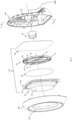
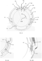
- FIG. 1 shows a front perspective view of a volatile composition dispenser 1(hereinafter “dispenser”) according to the present invention and FIG. 2 shows a rear perspective view of the dispenser 1.
- the dispenser 1 comprises a housing 10 having a front cover 100 and a rear frame 200, the front cover 100 and the rear frame 200 defining an interior space.
- the rear frame 200 is provided with a frame opening 201 (hereinafter “opening") located substantially in the centre of the rear frame 200.
- a push button 20 (hereinafter “button”) is disposed within the opening 201 and is movable with respect to the rear frame 200 for enabling a user to activate the dispenser 1.
- a cartridge 30 containing a volatile composition 31 is located within the housing 10.
- FIG. 3 shows internal components of the dispenser 1.
- the front cover 100 comprises a window 101 configured for displaying the cartridge 30.
- the cartridge 30 comprises a container 32 having an orifice 321, within which the volatile composition 31 (as shown in FIG. 1 ) is stored.
- a rupturable substrate 33 is sealably attached to and covers the orifice 321 defining a reservoir to prevent the volatile composition 31 from being released until the dispenser 1 is activated.
- the rupturable substrate 33 may be ruptured to release the volatile composition 31 by actuating a rupture mechanism 34 positioned adjacent to the rupturable substrate 33.
- the rupture mechanism 34 comprises a movable member 35 movably attached to an outer frame 36 by a resilient member 38.
- the resilient member 38 may be formed of one or more springs 38.
- the rupture element 37 is arranged within the rupture mechanism 34 to puncture holes in the rupturable substrate 33.
- the rupture element 37 may be a pin.
- the cartridge 30 may comprise a membrane 39 located on the exterior of the cartridge 30.
- the membrane 39 may be sealably attached to a flange 322 located at a periphery 323 of the container 32.
- the membrane 39 encloses the container 32, the volatile composition 31, the rupturable substrate 33, and the rupture mechanism 34.
- the membrane 39 may be configured to flex when a pressure or an actuation force is applied on the membrane 39.
- a user depresses the button 20 until it makes contact with the rupture mechanism 34 (through the membrane 39), and the pins 37 on the rupture mechanism 34 pierce the rupturable substrate 33. Once the rupturable substrate 33 is pierced, the volatile composition 31 flows out of the container 32, wets the membrane 39 and is then delivered to the atmosphere surroundings through evaporation from the membrane 39.
- the button 20 and the rear frame 200 are configured to enable efficient and controlled rupturing of the rupturable substrate 33 in the cartridge 30 while additionally providing a tactile and intuitive user experience to the user for activating the dispenser 1.
- FIG. 4 shows a side section view A-A of the rear frame 200.
- An inner wall 40 is provided at a periphery 207 of the opening 201 and extends into the housing 10 from the interior of the rear frame 200.
- the inner wall 40 has a proximal end 41 flush with the periphery 207 of the opening 201, and a distal end 42 protruding into the housing 10.
- the inner wall 40 is solid and tubular in shape.
- the inner wall 40 may take some other shape such as for example a square cross section or a rectangular cross section.
- the inner wall 40 may be substantially cylindrical and comprise a continuous wall, or a segmented wall such as for example, a lattice structure or multiple elongate struts connected to one another.
- the inner wall 40 may define an extension of the opening 201 into the housing 10 with a central longitudinal axis 1000 running through the centre of the opening 201 and along which the button 20 can be depressed.
- the inner wall 40 may protrude out of the housing 10 such that the inner wall 40 defines an extension of the opening 201 out of the housing 10. Accordingly, the distal end 42 may be flush with the periphery 207 of the opening 201 and the proximal end 41 may protrude out of the housing 10.
- FIG. 5 is a front section view of the button 20 configured to fit and to move within the opening 201 of the rear frame 200.
- the button 20 comprises a top 21 and a button body 22 extending from the top 21 into the housing 10.
- the top 21 is located in line with the periphery 207 of the opening 201 when the button 20 is in an "at rest" position (see for example FIG. 14A ).
- the top 21 of the button 20 may protrude out of the opening 201 when "at rest” (see for example. FIG.15A).
- the button body 22 extends substantially in parallel to the inner wall 40. Therefore the button body 22 may also have a tubular shape.
- One or more protrusions 50 extend from the button body 22 to define snap fits for assembling the button 20 to the inner wall 40.
- the dispenser 1 comprises an interlocking mechanism for preventing motion of the button 20 with respect to the rear frame 200 after activation of the dispenser 1.
- the interlocking mechanism may comprise a snap-fit or interlocking joint.
- the interlocking mechanism may comprise structural features integral with the button 20 or the inner wall 40 such as hooks or protrusions on the button 20 which, after depression of the button, engage with corresponding undercuts, detents, protrusions, or openings in the inner wall 40 to lock the button 20 to the inner wall 40. In this way, the button 20 may not be released from the post-activation position without forced failure of the interlocking mechanism or the joint.
- the interlocking mechanism may comprise at least one protrusion 51, 52 located on each of the inner wall 40 and the button body 22, aligned with one another such that they make contact as the button 20 is depressed.
- the first protrusion 51 may be located at the distal end 42 of the inner wall 40.
- a second protrusion 52 may be located proximate a distal end 23 of the button body 22.
- the first protrusion 51 and the second protrusion 52 may be generally elongate and extend in a direction parallel to the longitudinal axis 1000 of the opening 201.
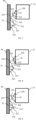
- FIG. 6A is a schematic drawing of the button 20 mounted within the rear frame 200 wherein the button 20 is in a "at rest” position.
- FIGS. 6B and 6C are schematic drawings depicting the movement of the button 20 between the “at rest” position to a post-activation position.
- the button 20 is configured to move linearly with respect to the rear frame 200, i.e. a straight push button that moves in a direction generally parallel to the longitudinal axis 1000 of the frame opening 201 upon depression of the button 20. Only the inner wall 40 and the button body 22 are shown to better illustrate the arrangement and movement of the button 20 relative to the inner wall 40.
- the first and second protrusions 51, 52 are arranged within a gap 60 between the button body 22 and the inner wall 40 and are aligned to engage with one another in the plane generally parallel to the longitudinal axis 1000 of the frame opening 201.
- the size of the gap 60 may be uniform and constant along the longitudinal direction (length) of the button body 22.
- the gap 60 may comprise a first gap width (W1) between respective bases 511, 521 of the first and second protrusions 51, 52. Specifically, W1 is less than a sum of a depth (D1) of the first protrusion 51 relative to the inner wall 40 and a depth (D2) of the second protrusion 52 relative to the button body 22, and may be represented by the following formula: W 1 ⁇ D 1 + D 2
- the first gap width, W1 is configured to enable the first and second protrusions 51, 52 to be engaged while enabling free movement of the button 20 prior to locking of the button 20 within the rear frame 200.
- the protrusion depth, D1 of the first protrusion 51 may be in the range of 1% to 2% of a width, W2 of the inner wall 40.
- the protrusion depth D2 of the second protrusion 52 may be in the range of 1% to 2% of a width, W3 of the button body 22.
- At least one of the first and second protrusions 51, 52 may be asymmetrical along its length, with a first surface 512, 522 facing the other of the first and second protrusions 51, 52 (when in a rest position) and a second surface 513, 523 facing away from the other of the first and second protrusions 51, 52.
- a tip 514 is positioned between the first surface 512 and the second surface 513 of the first protrusion 51.
- the second protrusion 52 may have a symmetrical, or substantially symmetrical, form with, for example, a tip 524 for engaging the first surface 512 of the first protrusion 51.
- the first and second protrusions 51, 52 are spaced apart such as for example, the distal end 23 of the button body 22 may be proximal to the distal end 42 of the inner wall 40.
- the button 20 is depressed and, as the button 20 moves relative to the inner wall 40, the first and second protrusions 51, 52 make contact (as shown in FIG. 6B ) through engagement of the tip 524 of the second protrusion 52 with the first surface 512 of the first protrusion 51.
- the first and second protrusions 51, 52 move past one another until the second protrusion 52 (on the button body 22) is proximal to the distal end 42 of the inner wall 40 (as shown in FIG. 6C ).
- the second protrusion 52 is below the first protrusion 51 in a vertical direction parallel to the longitudinal axis 1000.
- the second surfaces 513, 523 of the first and second protrusions 51, 52 may be adjacent to each other in the post activation position.
- FIGS. 7 to 9 are schematic drawings showing variations in the geometry of the first and second protrusions 51, 52 for locking the button 20 to the rear frame 200 upon depression of the button 30.
- An angle 515, 525 of the first surfaces 512, 522 and an angle 516, 526 of the second surfaces 513, 523 relative to respectively the inner wall 40 or button body 22 may be different.
- the angle 515 of the first surface 512 relative to the inner wall 40 may be greater than the angle 516 of the second surface 513 relative to the inner wall 40.
- the angle 515, 525 of the first surface 512, 522 of one or both of the first or second protrusions 51, 52 may be between 80° and 150°, whereas the angle 516, 526 of the second surface 513, 523 of one or both of the first and second protrusions 51, 52 is between 5°and 80°.
- the protrusions 51, 52 may have an assymetrical form, whereas the other protrusion 51, 52 may have a symmetrical, or substantially symmetrical, form with, for example, a rounded tip.
- the second surfaces 513, 523 of both the first and second protrusions 51, 52 may have corresponding angles relative respectively to the inner wall 40 and button body 22 such that following activation, the protrusions 51, 52 lock together.
- the angle 516, 526 of the second surfaces 513, 523 of both the first and second protrusions 51, 52 may be between 90° and 150°.
- first surfaces 512, 522, and second surfaces 513, 523 result in the button body 22 flexing and snapping into place after the first and second protrusions 51, 52 have moved past one another thereby providing the user with a clear intuitive signal (and preferably an audible click).
- one of the first protrusion 51 and the second protrusion 52 may be configured to deflect to enable the second protrusion 52 to move past the first protrusion 51 into a second position as shown in FIG. 6C .
- the second protrusion 52 of the button 20 may be configured to be rigid to transmit the force exerted by the user on the button 20 to rupture the rupturable substrate 33 in the cartridge 30.
- the second protrusion 52 may be configured to be resilient to generate a clicking sound when the second protrusion 52 contacts the first protrusion 51 after it moves past the first protrusion 51.
- the button body 22 may be formed of a plurality of flexible wall sections 25 wherein the second protrusion 52 is disposed on a flexible wall section 25.
- the flexible wall sections 25 are configured to flex by forming channels 26 in the button body 22 adjacent to the second protrusions 52.
- Each channel 26 may comprise a length L1 substantially parallel to the longitudinal axis 1000 and configured to make the wall section 25 flexible for ease of activation.
- At least one channel 26 may define a substantially U-shape.
- Another advantage of having the second protrusions 52 disposed on the flexible wall sections 25 is that to avoid plastic deformations on the first protrusions 51 and the second protrusions 52.
- the flexing of the flexible wall sections 25 to contact the inner wall 40 generates a click sound and a tactile feeling is provided to the user thereby providing audible and tactile signals at the same time indicating that the dispenser 1 is activated.
- the first protrusion 51 may be a continuous lip extending circumferentially around the inner wall 40 wherein the second protrusion 52 of the button 20 is aligned for engaging and moving past the first protrusion 51.
- the protrusions 51, 52 are configured for a straight push button within a rear frame.
- alternative designs and arrangements of the first protrusion 51 and the second protrusion 52 to enable a lockable button may be configured depending on a desired actuation of a button 20 within a rear frame 200. Such alternative designs will be described later in the following description with reference to FIG. 12 .
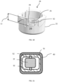
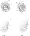
- FIG. 12 is a perspective view of the rear frame 200 of FIG. 3 (partially shown), FIG. 13A is a perspective view of the button 20 and FIG. 13B is a bottom view of the button 20.
- the first protrusion 51 or the second protrusion 52 may be generally elongate and extend in a direction parallel to the longitudinal axis 2000 of the frame opening 201.
- Each of the second protrusions 52 may comprise a length, L2 and each of the first protrusions 51 may comprise a length, L3.
- Each of the lengths L2 and L3 may be in the range of 7% to 20% of a length (L4) of the button 20.
- One or more second protrusions 52 may be disposed on a cam guide 80 for engaging the one or more first protrusions 51 during rotation of the button 20.
- the first protrusions 51 are disposed at the distal end 42 of the inner wall 40 wherein the first protrusion 51 is aligned for engaging the cam guide 80 of the button body 22.
- the cam guide 80 may comprise a plurality of first cam tracks 84 formed on the button body 22.
- the first cam tracks 84 are radially spaced apart on the button body 22 for engaging the first protrusions 51 on the distal end 42 of the inner wall 40.
- the cam guide 80 may further comprise a plurality of second cam tracks 85 intermediate the first cam tracks 84.
- a cam angle ⁇ of the cam guide 80 may be configured to obtain a desired button stroke S (mm) and a rotation angle ⁇ of the button 20 about the longitudinal axis 1000 and/or the cylindrical axis 2000 (shown in FIG. 17B ).
- the desired button stroke may be a distance to be travelled by the button 20 along the longitudinal axis 1000 of the opening 201 in order to cause the rupture elements 37 of the rupture mechanism 34 to puncture the substrate 33.
- the top 21 of the button 20 may have different orientations with respect to the rear frame 200 as shown in FIG.17A and FIG.17B .
- each second cam track 85 and a mating cam track 86 may be configured to correspond in shape or profile to the first step 84 so as to define a continuous cam profile for rotation of the button 20 about the longitudinal axis 1000 and axial movement of the button 20 along the longitudinal axis 1000.
- the second cam tracks 85 and the mating cam tracks 86 may be configured to allow the button 20 to be arranged within the frame 200 at a height relative to the distal end 42 of the inner wall 40. The height may be varied so that upon assembly, the button 20 may be either flush with the periphery 207 of the opening 201 in the first position (as shown in FIG. 17A ) or extending above the periphery 207 of the opening 201 in the first position (as shown in FIG. 18A ).
- indicia 90 may be disposed on the top 21 of the button 20 to provide a signal to a user of the dispenser 1.
- the indicia 90 may include a graphical representation like hands of a clock to show the button 20 in one orientation relative to the periphery of the opening in the first position and in a different orientation in the second position.
- the indicia 90 may be a graphical symbol indicating a position for actuating the button 20 or activating the dispenser 1.
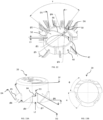
- FIG. 14A is a partial perspective view of the button 20 mounted within the rear frame 200 wherein the button 20 is in a "at rest” position.
- FIGS. 14B and 14C are cross-sectional views depicting the movement of the button 20 between the "at rest” position to a post-activation position.
- the button 20 is in the rest position ("first position"). In the first position, a first protrusion 51 (shown in broken lines) engages the cam guide 80 (broken lines on the button body 22) and is aligned with the distal end 23 of the button 20.
- the button 20 is moved into the housing (10) and, as the first protrusion 51 and the cam guide 80 engage throughout the movement of the button 20 (as shown in FIG. 14B ), the button 20 rotates and moves axially along the longitudinal axis 1000 until the distal end 23 of the button 20 extends into the housing 10 of FIG.
- L2 is greater than L3. Still further, L3 may be in the range of 1% to 55% of L2.
- FIG. 15 is an interior section view of the first protrusions 51 and the second protrusions 52 when the button 20 is in the rest position before activation and corresponds to FIG. 14A .
- FIGS. 16A is a detailed view of FIG. 15 and FIG. 16B show the first protrusions 51 and the second protrusions 52 when the button 20 is in the post-activation position after activation.
- the first and second protrusions 51, 52 may be radially and axially spaced apart about the longitudinal axis 1000 and arranged within the gap 60 between the button body 22 and the inner wall 40 to allow for locking of the button 20 upon activation.
- the button body 22 comprises a stepped outer surface 221 configured to mate with a stepped inner surface 401 of the inner wall 40 for slidable movement of the button 20 within the rear frame opening 201 and arranged to form variable gap widths including the first gap width W1 and a second gap width W4 within the gap 60.
- the second protrusion 52 is radially spaced apart from the first protrusion 51 and is aligned to engage with and move past the first protrusion 51 in a radial direction 1100 about the longitudinal axis 1000.
- the number of first protrusions 51 on the inner wall 40 and the number of second protrusions 52 on the button 20 may be equivalent and varied according to a diameter or width of the button body 22.
- three first protrusions 51 are disposed on and spaced circumferentially on the inner wall 40 and a corresponding number of second protrusions 52 are disposed on and spaced circumferentially on the button body 22.
- the dispenser 1 may further comprise a third protrusion 53 disposed within the gap 60 for preventing free movement of the button 20 in the at rest position.
- the third protrusion 53 may be integral with the first protrusion 51 as shown in FIG. 15B.
- the inner wall 40, the first protrusion 51 and the frame 200 may be molded and form a unitary unit and may comprise plastic for ease of manufacturing.
- the second protrusion 52, the cam guide 80 and the button 20 may also be molded and form a unitary plastic component.
- the button 20, and the frame 200 and the first and second protrusions 51, 52 may comprise sheet metal, such as spring steel, and may be stamped or milled to form a unitary metal component.
- the volatile composition dispenser 1 may comprise a small form factor such as a form factor similar to a computer mouse so as for ergonomic fit in the hand of the user and ease of use.
- physical specifications of the inner wall 40, the button 20, the first and second protrusion 51, and the cam guide 80 may be configured based on a specified button stroke S (millimeters) and/or a specified rotation angle ⁇ (degrees) of the button 20 relative to the longitudinal axis 1000 as shown in FIG. 17B .
- Table 1 sets out physical specifications of the inner wall 40, the button 20, the protrusions 51, 52 and the cam guide 80 based on a button stroke S of 4.25 mm and a rotation angle ⁇ of 42.5 degrees.
- the internal components of the cartridge 30 as shown in FIG. 3 may be characterized as follows.
- dimensions of the container 32 may be configured to hold about 1 ml to about 50 ml of a liquid volatile composition.
- the reservoir 52 may hold about 2 ml to about 30 ml, alternatively about 2 ml to about 10 ml, alternatively about 2 ml to about 8 ml, alternatively about 4 ml to about 6 ml, alternatively about 2 ml, alternatively about 6 ml of a liquid volatile composition.
- a shape of the container 32 may be configured to correspond to a shape of the opening 101 of the front cover 100.
- the container 32 may define a substantially elliptical or oval shape and its width to length ratio may be about 1:2 to 1:2.5.
- the rupturable substrate 33 can be made of any material that ruptures with applied force, with or without the presence of an element to aid in such rupture. Because the rupturable substrate 33 is intended to contain a volatile material while in storage, it may be made from any barrier material that prevents evaporation of the volatile material prior to its intended use. Such materials may be impermeable to vapors and liquids. Suitable barrier materials for the rupturable substrate 33 include a flexible film, such as a polymeric film, a flexible foil, or a composite material such as foil/polymeric film laminate.
- Suitable flexible foils include a metal foil such as a foil comprised of a nitrocellulose protective lacquer, a 20 micron aluminum foil, a polyurethane primer, and 15 g/m2 polyethylene coating (Lidfoil 118-0092), available from Alcan Packaging.
- Suitable polymeric films include polyethylene terephtalate (PET) films, acrylonitrile copolymer barrier films such as those sold under the tradename Barex ® by INOES, ethylene vinyl alcohol, and combinations thereof. It is also contemplated that coated barrier films may be utilized as a rupturable substrate 33.
- Such coated barrier films include metallized PET, metalized polypropylene, silica or alumina coated film may be used. Any barrier material, whether coated or uncoated, may be used alone and or in combination with other barrier materials.
- the rupture element 37 can be injection, compression, or pressure molded using a polyolefin, such as polyethylene or polypropylene; polyester; or other plastics known to be suitable for molding.
- the rupture element 130 could also be made by thermoforming with a discrete cutting step to remove parts not wanted.
- the membrane 39 may have an average pore size of about 0.01 to about 0.06 microns, alternatively from about 0.01 to about 0.05 microns, alternatively about 0.01 to about 0.04 microns, alternatively about 0.01 to about 0.03 microns, alternatively about 0.02 to about 0.04 microns, alternatively about 0.02 microns. Further, the membrane 39 may be filled with any suitable filler and plasticizer known in the art. Fillers may include finely divided silica, clays, zeolites, carbonates, charcoals, and mixtures thereof. The microporous membrane 39 may be filled with about 50% to about 80%, by total weight, of silica, alternatively about 60% to about 80%, alternatively about 70% to about 80%, alternatively about 70% to about 75%. A thickness of the membrane 39 may be about 0.01 mm to about 1 mm, alternatively between about 0.1 mm to 0.4 mm, alternatively about 0.15 mm to about 0.35 mm, alternatively about 0.25 mm.
- an evaporative surface area of the microporous membrane 39 may be about 2 cm 2 to about 100 cm 2 , alternatively about 2 cm 2 to about 25 cm 2 , alternatively about 10 cm 2 to about 50 cm 2 , alternatively about 10 cm 2 to about 45 cm 2 , alternatively about 10 cm 2 to about 35 cm 2 , alternatively about 15 cm 2 to about 40 cm 2 , alternatively about 15 cm 2 to about 35 cm 2 , alternatively about 20 cm 2 to about 35 cm 2 , alternatively about 30 cm 2 to about 35 cm 2 , alternatively about 35 cm 2 .
- the rear frame 200 may be sized and shaped to fit the evaporative surface area of the membrane 39.
- Suitable microporous membranes for the present invention include a microporous, ultra-high molecular weight polyethylene (UHMWPE) optionally filled with silica as described in U.S. 7,498,369 .
- UHMWPE microporous membranes include Daramic TM V5, available from Daramic, Solupor ® , available from DSM (Netherlands), and Teslin TM , available from PPG Industries, and combinations thereof.
- a volatile material or composition suitable for use in the cartridge 30 for a volatile composition dispenser 1 may be configured to condition, modify, or otherwise change the atmosphere and may include compositions suitable for the purposes of providing fragrances, air fresheners, deodorizers, odor eliminators, malodor counteractants, insecticides, insect repellants, medicinal substances, disinfectants, sanitizers, mood enhancers, and aromatherapy aids.
- a list of the suitable volatile materials is shown in Table 2 below.
- Table 2 Purpose Volatile Material Providing fragrances Perfume oil, volatile essential oils, volatile organic compound, synthetically or naturally formed materials.
- Examples include, but are not limited to: oil of bergamot, bitter orange, lemon, mandarin, caraway, cedar leaf, clove leaf, cedar wood, geranium, lavender, orange, origanum, petitgrain, white cedar, patchouli, neroili, rose absolute, and the like.
- Suitable crystalline solids include but are not limited to: vanillin, ethyl vanillin, coumarin, tonalid, calone, heliotropene, musk xylol, cedrol, musk ketone benzohenone, raspberry ketone, methyl naphthyl ketone beta, phenyl ethyl salicylate, veltol, maltol, maple lactone, proeugenol acetate, evemyl, and the like.
- Suitable malodor compositions include reactive aldehydes and ionones
- the volatile material mixture may include 0% to about 15%, by total weight, of volatile materials each having a VP at 25°C of about 0.004 torr to about 0.035 torr; and 0% to about 25%, by total weight, of volatile materials each having a VP at 25°C of about 0.1 torr to about 0.325 torr; and about 65% to about 100%, by total weight, of volatile materials each having a VP at 25°C of about 0.035 torr to about 0.1 torr.
- One source for obtaining the saturation vapor pressure of a volatile material is EPI Suite TM , version 4.0, available from U.S. Environmental Protection Agency.
Landscapes
- Life Sciences & Earth Sciences (AREA)
- Health & Medical Sciences (AREA)
- Pest Control & Pesticides (AREA)
- General Health & Medical Sciences (AREA)
- Epidemiology (AREA)
- Animal Behavior & Ethology (AREA)
- Public Health (AREA)
- Veterinary Medicine (AREA)
- Toxicology (AREA)
- Engineering & Computer Science (AREA)
- Insects & Arthropods (AREA)
- Wood Science & Technology (AREA)
- Zoology (AREA)
- Environmental Sciences (AREA)
- Packaging Of Annular Or Rod-Shaped Articles, Wearing Apparel, Cassettes, Or The Like (AREA)
- Disinfection, Sterilisation Or Deodorisation Of Air (AREA)
- Catching Or Destruction (AREA)
Claims (14)
- Spender (1) für eine flüchtige Zusammensetzung, umfassend:a) ein Gehäuse (10), umfassend einen hinteren Rahmen (200), wobei der hintere Rahmen (200) eine Rahmenöffnung (201), die eine Längsachse (1000) aufweist, umfasst;b) eine Innenwand (40), die sich von der Rahmenöffnung (201) erstreckt, die Innenwand (40) umfassend ein proximales Ende (41) an äußeren Rand (207) der Öffnung (201) und ein distales Ende (42);c) einen Druckknopf (20), der konfiguriert ist, um innerhalb der Rahmenöffnung (201) von einer ersten Position in eine zweite Position relativ zu dem distalen Ende (42) der Innenwand (40) beweglich zu sein, wobei der Druckknopf (20) einen Knopfkörper (22) umfasst;d) mindestens einen ersten Vorsprung (51), der sich an dem distalen Ende (42) der Innenwand (40) befindet; e) mindestens einen zweiten Vorsprung (52), der auf dem Knopfkörper (22) angeordnet ist, wobei der zweite Vorsprung (52) ausgerichtet ist, um mit dem ersten Vorsprung (51) in Eingriff zu kommen und sich an diesem vorbei zu bewegen, wenn der Knopf (20) von der ersten Position in die zweite Position bewegt wird, wobei der zweite Vorsprung (52) unterhalb des ersten Vorsprungs (51), relativ zu dem distalen Ende (42) der Innenwand (40) in einer vertikalen Richtung parallel zu der Längsachse (1000) liegt, um eine Rückkehr des Knopfs (20) in die erste Position zu verhindern; undf) eine Kartusche (30) mit einer flüchtigen Zusammensetzung, die innerhalb des Gehäuses (10) zu dem Druckknopf (20) benachbart angeordnet ist, die Kartusche (30) umfassend einen Behälter (32), der eine Öffnung (321) aufweist, in dem die flüchtige Zusammensetzung (31) aufbewahrt wird, ein aufreißbares Substrat (33), das an der Öffnung (321) abdichtend angebracht ist und diese abdeckt, einen Reißmechanismus (34), der zu dem aufreißbaren Substrat (33) benachbart positioniert ist, und ein oder mehrere Reißelemente (37), die innerhalb des Reißmechanismus (34) eingerichtet sind;wobei der Knopf (20) gedrückt wird, bis er mit dem Reißmechanismus (34) in Berührung ist; und das eine oder die mehreren Reißelemente (37) an dem Reißmechanismus (34) das aufreißbare Substrat (33) durchdringen.
- Spender (1) für eine flüchtige Zusammensetzung nach Anspruch 1, ferner umfassend einen Spalt (60) zwischen dem Knopfkörper (22) und der Innenwand (40), wobei der Spalt (60) eine Spaltbreite (W1) zwischen einer Basis (521) des zweiten Vorsprungs (52) auf dem Knopfkörper (22) und einer Basis (511) des ersten Vorsprungs (51) auf der Innenwand (40) umfasst, wobei die Spaltbreite (W1) geringer als die Summe einer Tiefe (D1) des ersten Vorsprungs (51) relativ zu der Innenwand (40) und einer Tiefe (D2) des zweiten Vorsprungs (52) relativ zu dem Knopfkörper (22) ist.
- Spender (1) für eine flüchtige Zusammensetzung nach einem der Ansprüche 1 bis 2, wobei einer des ersten Vorsprungs (51) und des zweiten Vorsprungs (52) umfasst:eine erste Oberfläche (512, 522) zum Eingreifen in den anderen des ersten Vorsprungs (51) und des zweiten Vorsprungs (52);eine zweite Oberfläche (513, 523), die der ersten Oberfläche (512, 522) gegenüberliegt;wobei ein Winkel (515, 525) der ersten Oberfläche (512, 522) relativ zu der Innenwand (40) oder zu dem Knopfkörper (22) größer als ein Winkel (516, 526) der zweiten Oberfläche (513, 523) relativ zu der Innenwand (40) oder zu dem Knopfkörper (22) ist.
- Spender (1) für eine flüchtige Zusammensetzung nach Anspruch 3, wobei der Winkel (516, 526) der zweiten Oberfläche (513, 523) relativ zu der Innenwand (40) oder dem Knopfkörper (22) größer als 30 Grad und kleiner als oder gleich 90 Grad ist.
- Spender (1) für eine flüchtige Zusammensetzung nach einem der vorstehenden Ansprüche, wobei einer des ersten Vorsprungs (51) und des zweiten Vorsprungs (52) eine ununterbrochene Lippe ist, die sich um die Innenwand (40) oder den Knopfkörper (22) herum umlaufend erstreckt.
- Spender (1) für eine flüchtige Zusammensetzung nach einem der Ansprüche 1 bis 4, wobei der Knopfkörper (22) und die Innenwand (40) im Wesentlichen zylindrisch sind, und der Spender umfasst:eine Vielzahl von ersten Vorsprüngen (51), die auf der Innenwand (40) umlaufend beabstandet sind;eine Vielzahl von zweiten Vorsprüngen (52), die auf dem Knopfkörper (22) umlaufend beabstandet sind.
- Spender (1) für eine flüchtige Zusammensetzung nach Anspruch 6, wobei mindestens einer der Vielzahl von ersten Vorsprüngen (51) und zweiten Vorsprüngen (52) im Allgemeinen länglich ist und sich in einer Richtung parallel zu der Längsachse (1000) der Rahmenöffnung (201) erstreckt.
- Spender (1) für eine flüchtige Zusammensetzung nach Anspruch 7, wobei jeder der zweiten Vorsprünge (52) eine Länge (L2) umfasst und jeder der ersten Vorsprünge (51) eine Länge (L3) umfasst, wobei jede von L2 und L3 in dem Bereich von 7 % bis 20 % einer Länge (L4) des Knopfs (20) liegen und L2 größer als L3 ist.
- Spender (1) für eine flüchtige Zusammensetzung nach Anspruch 8, wobei L3 in dem Bereich von 1 % bis 55 % von L2 liegt.
- Spender (1) für eine flüchtige Zusammensetzung nach einem der vorstehenden Ansprüche, ferner umfassend eine Nockenführung (80), die auf dem Knopfkörper (22) angeordnet ist, und mindestens einen Vorsprung (51), der sich auf der Innenwand 40 befindet und mit der Nockenführung (80) ausgerichtet ist.
- Spender (1) für eine flüchtige Zusammensetzung nach einem der vorstehenden Ansprüche, ferner umfassend eine vordere Abdeckung (100), die konfiguriert ist, um an dem hinteren Rahmen (200) angebracht zu werden, um das Gehäuse (10) zum Tragen der Kartusche (30) auszubilden.
- Verfahren zum Zusammenbauen eines Gehäuses für einen Spender für eine flüchtige Zusammensetzung nach einem der Ansprüche 1 bis 11, das Verfahren umfassend:Bereitstellen eines Gehäuses (10), umfassend einen hinteren Rahmen (200) und eine Kartusche (30) für eine flüchtige Zusammensetzung, die in dem Gehäuse (10) angeordnet ist, wobei der hintere Rahmen (200) eine Rahmenöffnung (201), die eine Längsachse (1000) aufweist, umfasst;Bereitstellen einer Innenwand (40) in der Öffnung (201), die Innenwand (40) umfassend ein proximales Ende (41) und ein distales Ende (42), wobei sich mindestens ein erster Vorsprung (51) an dem distalen Ende (42) der Innenwand (40) befindet;Bereitstellen eines Knopfs (20) innerhalb der Rahmenöffnung (201), wobei der Knopf von einer ersten Position in eine zweite Position relativ zu dem distalen Ende (42) der Innenwand (40) beweglich ist, wobei der Knopf (20) einen Knopfkörper (22) und mindestens einen zweiten Vorsprung (52) umfasst, der auf dem Knopfkörper (22) angeordnet ist, zum Ineingriffbringen des zweiten Vorsprungs (52) auf dem Knopfkörper (22) mit dem ersten Vorsprung (51) auf der Innenwand (40) und sich beim Drücken des Knopfs an diesem vorbei zu bewegen.
- Verfahren zum Verriegeln eines Druckknopfs (20) innerhalb eines Gehäuses (10) eines Spenders für flüchtige Zusammensetzungen nach einem der Ansprüche 1 bis 11, das Verfahren umfassend:Bereitstellen eines Gehäuses (10), umfassend einen hinteren Rahmen (200) und eine Kartusche (30) für eine flüchtige Zusammensetzung, die in dem Gehäuse (10) angeordnet ist, wobei der hintere Rahmen (200) eine Rahmenöffnung (201), die eine Längsachse (1000) aufweist, umfasst;Bereitstellen einer Innenwand (40) in der Öffnung (201), die Innenwand (40) umfassend ein proximales Ende (41) und ein distales Ende (42), wobei sich mindestens ein erster Vorsprung (51) an dem distalen Ende (42) der Innenwand (40) befindet;Bewegen eines Druckknopfs (20) innerhalb der Rahmenöffnung (201), wobei der Knopf (20) einen Knopfkörper (22) und mindestens einen zweiten Vorsprung (52), der auf dem Knopfkörper (22) angeordnet ist, umfasst;Ineingriffbringen des mindestens einen zweiten Vorsprungs (52), der an dem Knopfkörper (22) angeordnet ist, mit dem ersten Vorsprung (51) an der Innenwand (40) und Vorbeibewegen an diesem, um eine Rückkehr des Knopfs (20) in die erste Position zu verhindern.
- Verfahren nach Anspruch 13, wobei das Bewegen des Druckknopfs (20) eine axiale Bewegung des Druckknopfs (20) entlang der Längsachse (1000) und eine Drehung des Knopfs (20) um die Längsachse (1000) herum umfasst.
Applications Claiming Priority (2)
| Application Number | Priority Date | Filing Date | Title |
|---|---|---|---|
| US201662330865P | 2016-05-03 | 2016-05-03 | |
| PCT/US2017/030713 WO2017192638A1 (en) | 2016-05-03 | 2017-05-03 | Volatile composition dispenser with lockable push button |
Publications (2)
| Publication Number | Publication Date |
|---|---|
| EP3452113A1 EP3452113A1 (de) | 2019-03-13 |
| EP3452113B1 true EP3452113B1 (de) | 2025-03-05 |
Family
ID=58699304
Family Applications (1)
| Application Number | Title | Priority Date | Filing Date |
|---|---|---|---|
| EP17722973.9A Active EP3452113B1 (de) | 2016-05-03 | 2017-05-03 | Spender für flüchtige zusammensetzung mit verriegelbarer drucktaste |
Country Status (4)
| Country | Link |
|---|---|
| US (1) | US10561754B2 (de) |
| EP (1) | EP3452113B1 (de) |
| JP (1) | JP6726763B2 (de) |
| WO (1) | WO2017192638A1 (de) |
Families Citing this family (24)
| Publication number | Priority date | Publication date | Assignee | Title |
|---|---|---|---|---|
| USD816822S1 (en) * | 2015-05-15 | 2018-05-01 | The Procter & Gamble Company | Air freshener device |
| US10471168B2 (en) | 2016-05-03 | 2019-11-12 | The Procter & Gamble Company | Volatile composition dispenser with increased membrane exposure and volatile composition weight loss |
| CN112654373B (zh) | 2018-09-07 | 2022-11-04 | 宝洁公司 | 挥发性组合物分配器 |
| USD926303S1 (en) | 2018-09-28 | 2021-07-27 | The Procter & Gamble Company | Air freshener device |
| US11484022B2 (en) | 2019-10-15 | 2022-11-01 | S. C. Johnson & Son, Inc. | Insect trap device |
| US12290060B2 (en) | 2019-10-15 | 2025-05-06 | S. C. Johnson & Son, Inc. | Insect trap device |
| WO2023063309A1 (ja) * | 2021-10-14 | 2023-04-20 | 小林製薬株式会社 | 揮散装置 |
| JP2023058970A (ja) * | 2021-10-14 | 2023-04-26 | 小林製薬株式会社 | 揮散装置 |
| JP2023058972A (ja) * | 2021-10-14 | 2023-04-26 | 小林製薬株式会社 | 揮散装置 |
| JP7770858B2 (ja) * | 2021-10-14 | 2025-11-17 | 小林製薬株式会社 | 揮散装置 |
| JP7818931B2 (ja) * | 2021-11-11 | 2026-02-24 | 小林製薬株式会社 | 揮散装置 |
| JP7818932B2 (ja) * | 2021-11-11 | 2026-02-24 | 小林製薬株式会社 | 揮散装置 |
| USD1010060S1 (en) | 2022-02-09 | 2024-01-02 | S. C. Johnson & Son, Inc. | Substrate |
| USD1031910S1 (en) | 2022-02-09 | 2024-06-18 | S. C. Johnson & Son, Inc. | Insect trap |
| USD972065S1 (en) * | 2022-08-08 | 2022-12-06 | Christopher Hopkins | Scent dispersing trolling lure |
| WO2024253988A1 (en) | 2023-06-05 | 2024-12-12 | The Procter & Gamble Company | Housing for volatile composition dispenser |
| WO2024253990A1 (en) | 2023-06-05 | 2024-12-12 | The Procter & Gamble Company | Consumer product containing volatile composition cartridge |
| CN121368494A (zh) | 2023-06-05 | 2026-01-20 | 宝洁公司 | 可再填充挥发性组合物分配器 |
| WO2025136727A1 (en) | 2023-12-19 | 2025-06-26 | The Procter & Gamble Company | Delivery engine and apparatus for delivering a volatile material |
| US20250295829A1 (en) | 2024-03-19 | 2025-09-25 | The Procter & Gamble Company | Packaging for volatile composition dispenser cartridge |
| US20250296767A1 (en) | 2024-03-19 | 2025-09-25 | The Procter & Gamble Company | Cartridge with laser marking |
| USD1111150S1 (en) * | 2024-04-24 | 2026-02-03 | Brandywine Product Group International Inc. | Fragrance membrane housing component |
| WO2026029952A1 (en) | 2024-07-30 | 2026-02-05 | The Procter & Gamble Company | Housing for volatile composition dispenser |
| WO2026029953A1 (en) | 2024-07-30 | 2026-02-05 | The Procter & Gamble Company | Cartridge for delivering a volatile material |
Citations (3)
| Publication number | Priority date | Publication date | Assignee | Title |
|---|---|---|---|---|
| US4995555A (en) * | 1988-11-14 | 1991-02-26 | American Cyanamid Company | Air treatment device and method |
| EP1205193A1 (de) * | 2000-11-07 | 2002-05-15 | The Procter & Gamble Company | Einfach aktivierbares, selbstheizendes Gerät zur Verteilung von flüchtigen Stoffen |
| WO2006061803A1 (en) * | 2004-12-10 | 2006-06-15 | Firmenich Sa | A device for dispensing a volatile liquid and method for its activation |
Family Cites Families (18)
| Publication number | Priority date | Publication date | Assignee | Title |
|---|---|---|---|---|
| US4382548A (en) * | 1981-07-09 | 1983-05-10 | Heijden Joahnnes V D | Dispenser for air-treating vapors |
| US4572375A (en) * | 1984-11-26 | 1986-02-25 | Baer Carl D | Container for dispersant |
| WO1998016262A1 (en) | 1996-10-16 | 1998-04-23 | S.C. Johnson & Son, Inc. | Air freshener device with dispensing actuator feature |
| IT243977Y1 (it) * | 1998-05-04 | 2002-03-07 | Beta Pictoris Inc | Contenitore in particolare per deodoranti, insetticidi, antitarme,con meccanismo di apertura e chiusura a scatto |
| IT1312222B1 (it) * | 1999-03-22 | 2002-04-09 | Siabs Industry S R L | Dispositivo di riscaldamento ad irraggiamento in particolare perambienti esterni. |
| JP4625569B2 (ja) * | 2000-10-04 | 2011-02-02 | 凸版印刷株式会社 | 倒立型揮散性薬剤発散器 |
| CN101073065A (zh) | 2004-12-10 | 2007-11-14 | 皇家飞利浦电子股份有限公司 | 多频带超宽带通信中的增强解码方法和装置 |
| US7204054B2 (en) * | 2005-02-04 | 2007-04-17 | Senoret Chemical Company | Insecticidal activatable bait station |
| KR100879563B1 (ko) * | 2007-10-25 | 2009-01-22 | 강완준 | 휴대형 방향캡슐 |
| US8740110B2 (en) | 2009-04-16 | 2014-06-03 | The Procter & Gamble Company | Apparatus for delivering a volatile material |
| US8931711B2 (en) | 2009-04-16 | 2015-01-13 | The Procter & Gamble Company | Apparatus for delivering a volatile material |
| WO2010121039A2 (en) * | 2009-04-16 | 2010-10-21 | The Procter & Gamble Company | Volatile composition dispenser |
| US8807538B2 (en) * | 2011-04-28 | 2014-08-19 | S.C. Johnson & Son, Inc. | Centrifugal fan device |
| US8622209B2 (en) * | 2011-06-09 | 2014-01-07 | Ica Trinova, Llc | Container for mixing |
| US9205165B2 (en) * | 2012-10-22 | 2015-12-08 | S.C. Johnson & Son, Inc. | Volatile material dispensing system having an adjustable diffusion apparatus |
| US9591842B2 (en) | 2013-08-30 | 2017-03-14 | S. C. Johnson & Son, Inc. | Passive volatile dispensing device |
| US9015989B1 (en) * | 2014-05-22 | 2015-04-28 | Bell Laboratories, Inc. | Ant bait dispenser |
| US20170043047A1 (en) | 2015-08-13 | 2017-02-16 | The Procter & Gamble Company | Volatile composition dispenser |
-
2017
- 2017-05-01 US US15/582,828 patent/US10561754B2/en active Active
- 2017-05-03 EP EP17722973.9A patent/EP3452113B1/de active Active
- 2017-05-03 JP JP2018554704A patent/JP6726763B2/ja active Active
- 2017-05-03 WO PCT/US2017/030713 patent/WO2017192638A1/en not_active Ceased
Patent Citations (3)
| Publication number | Priority date | Publication date | Assignee | Title |
|---|---|---|---|---|
| US4995555A (en) * | 1988-11-14 | 1991-02-26 | American Cyanamid Company | Air treatment device and method |
| EP1205193A1 (de) * | 2000-11-07 | 2002-05-15 | The Procter & Gamble Company | Einfach aktivierbares, selbstheizendes Gerät zur Verteilung von flüchtigen Stoffen |
| WO2006061803A1 (en) * | 2004-12-10 | 2006-06-15 | Firmenich Sa | A device for dispensing a volatile liquid and method for its activation |
Also Published As
| Publication number | Publication date |
|---|---|
| US20170319731A1 (en) | 2017-11-09 |
| WO2017192638A1 (en) | 2017-11-09 |
| JP2019513494A (ja) | 2019-05-30 |
| EP3452113A1 (de) | 2019-03-13 |
| US10561754B2 (en) | 2020-02-18 |
| JP6726763B2 (ja) | 2020-07-22 |
Similar Documents
| Publication | Publication Date | Title |
|---|---|---|
| EP3452113B1 (de) | Spender für flüchtige zusammensetzung mit verriegelbarer drucktaste | |
| EP3452116B1 (de) | Spender für flüchtige zusammensetzungen mit führungsmechanismus und verfahren zu dessen aktivierung | |
| US10561755B2 (en) | Volatile composition dispenser with retractable push button | |
| US11517643B2 (en) | Apparatus for delivering a volatile material | |
| CA2662816C (en) | Method for delivering a volatile material | |
| EP2238989B1 (de) | Nachfüllvorrichtung für ein flüchtiges Material | |
| US20240148927A1 (en) | Apparatus for delivering a volatile material | |
| CA2662806C (en) | Apparatus for delivering a volatile material | |
| US20240399010A1 (en) | Volatile composition dispenser with activation lever | |
| WO2025042882A1 (en) | Volatile composition dispenser with cartridge for multiple volatile compositions |
Legal Events
| Date | Code | Title | Description |
|---|---|---|---|
| STAA | Information on the status of an ep patent application or granted ep patent |
Free format text: STATUS: UNKNOWN |
|
| STAA | Information on the status of an ep patent application or granted ep patent |
Free format text: STATUS: THE INTERNATIONAL PUBLICATION HAS BEEN MADE |
|
| PUAI | Public reference made under article 153(3) epc to a published international application that has entered the european phase |
Free format text: ORIGINAL CODE: 0009012 |
|
| STAA | Information on the status of an ep patent application or granted ep patent |
Free format text: STATUS: REQUEST FOR EXAMINATION WAS MADE |
|
| 17P | Request for examination filed |
Effective date: 20181107 |
|
| AK | Designated contracting states |
Kind code of ref document: A1 Designated state(s): AL AT BE BG CH CY CZ DE DK EE ES FI FR GB GR HR HU IE IS IT LI LT LU LV MC MK MT NL NO PL PT RO RS SE SI SK SM TR |
|
| AX | Request for extension of the european patent |
Extension state: BA ME |
|
| DAV | Request for validation of the european patent (deleted) | ||
| DAX | Request for extension of the european patent (deleted) | ||
| STAA | Information on the status of an ep patent application or granted ep patent |
Free format text: STATUS: EXAMINATION IS IN PROGRESS |
|
| 17Q | First examination report despatched |
Effective date: 20220406 |
|
| P01 | Opt-out of the competence of the unified patent court (upc) registered |
Effective date: 20230429 |
|
| GRAP | Despatch of communication of intention to grant a patent |
Free format text: ORIGINAL CODE: EPIDOSNIGR1 |
|
| STAA | Information on the status of an ep patent application or granted ep patent |
Free format text: STATUS: GRANT OF PATENT IS INTENDED |
|
| INTG | Intention to grant announced |
Effective date: 20241018 |
|
| GRAS | Grant fee paid |
Free format text: ORIGINAL CODE: EPIDOSNIGR3 |
|
| GRAA | (expected) grant |
Free format text: ORIGINAL CODE: 0009210 |
|
| STAA | Information on the status of an ep patent application or granted ep patent |
Free format text: STATUS: THE PATENT HAS BEEN GRANTED |
|
| AK | Designated contracting states |
Kind code of ref document: B1 Designated state(s): AL AT BE BG CH CY CZ DE DK EE ES FI FR GB GR HR HU IE IS IT LI LT LU LV MC MK MT NL NO PL PT RO RS SE SI SK SM TR |
|
| REG | Reference to a national code |
Ref country code: GB Ref legal event code: FG4D |
|
| REG | Reference to a national code |
Ref country code: CH Ref legal event code: EP |
|
| REG | Reference to a national code |
Ref country code: IE Ref legal event code: FG4D |
|
| REG | Reference to a national code |
Ref country code: DE Ref legal event code: R096 Ref document number: 602017088154 Country of ref document: DE |
|
| PG25 | Lapsed in a contracting state [announced via postgrant information from national office to epo] |
Ref country code: RS Free format text: LAPSE BECAUSE OF FAILURE TO SUBMIT A TRANSLATION OF THE DESCRIPTION OR TO PAY THE FEE WITHIN THE PRESCRIBED TIME-LIMIT Effective date: 20250605 |
|
| PG25 | Lapsed in a contracting state [announced via postgrant information from national office to epo] |
Ref country code: FI Free format text: LAPSE BECAUSE OF FAILURE TO SUBMIT A TRANSLATION OF THE DESCRIPTION OR TO PAY THE FEE WITHIN THE PRESCRIBED TIME-LIMIT Effective date: 20250305 |
|
| REG | Reference to a national code |
Ref country code: NL Ref legal event code: MP Effective date: 20250305 |
|
| PG25 | Lapsed in a contracting state [announced via postgrant information from national office to epo] |
Ref country code: ES Free format text: LAPSE BECAUSE OF FAILURE TO SUBMIT A TRANSLATION OF THE DESCRIPTION OR TO PAY THE FEE WITHIN THE PRESCRIBED TIME-LIMIT Effective date: 20250305 |
|
| PGFP | Annual fee paid to national office [announced via postgrant information from national office to epo] |
Ref country code: GB Payment date: 20250401 Year of fee payment: 9 |
|
| REG | Reference to a national code |
Ref country code: LT Ref legal event code: MG9D |
|
| PG25 | Lapsed in a contracting state [announced via postgrant information from national office to epo] |
Ref country code: NO Free format text: LAPSE BECAUSE OF FAILURE TO SUBMIT A TRANSLATION OF THE DESCRIPTION OR TO PAY THE FEE WITHIN THE PRESCRIBED TIME-LIMIT Effective date: 20250605 |
|
| PG25 | Lapsed in a contracting state [announced via postgrant information from national office to epo] |
Ref country code: HR Free format text: LAPSE BECAUSE OF FAILURE TO SUBMIT A TRANSLATION OF THE DESCRIPTION OR TO PAY THE FEE WITHIN THE PRESCRIBED TIME-LIMIT Effective date: 20250305 |
|
| PG25 | Lapsed in a contracting state [announced via postgrant information from national office to epo] |
Ref country code: LV Free format text: LAPSE BECAUSE OF FAILURE TO SUBMIT A TRANSLATION OF THE DESCRIPTION OR TO PAY THE FEE WITHIN THE PRESCRIBED TIME-LIMIT Effective date: 20250305 |
|
| PG25 | Lapsed in a contracting state [announced via postgrant information from national office to epo] |
Ref country code: BG Free format text: LAPSE BECAUSE OF FAILURE TO SUBMIT A TRANSLATION OF THE DESCRIPTION OR TO PAY THE FEE WITHIN THE PRESCRIBED TIME-LIMIT Effective date: 20250305 Ref country code: GR Free format text: LAPSE BECAUSE OF FAILURE TO SUBMIT A TRANSLATION OF THE DESCRIPTION OR TO PAY THE FEE WITHIN THE PRESCRIBED TIME-LIMIT Effective date: 20250606 |
|
| REG | Reference to a national code |
Ref country code: AT Ref legal event code: MK05 Ref document number: 1772322 Country of ref document: AT Kind code of ref document: T Effective date: 20250305 |
|
| PG25 | Lapsed in a contracting state [announced via postgrant information from national office to epo] |
Ref country code: NL Free format text: LAPSE BECAUSE OF FAILURE TO SUBMIT A TRANSLATION OF THE DESCRIPTION OR TO PAY THE FEE WITHIN THE PRESCRIBED TIME-LIMIT Effective date: 20250305 |
|
| PG25 | Lapsed in a contracting state [announced via postgrant information from national office to epo] |
Ref country code: SE Free format text: LAPSE BECAUSE OF FAILURE TO SUBMIT A TRANSLATION OF THE DESCRIPTION OR TO PAY THE FEE WITHIN THE PRESCRIBED TIME-LIMIT Effective date: 20250305 |
|
| PG25 | Lapsed in a contracting state [announced via postgrant information from national office to epo] |
Ref country code: SM Free format text: LAPSE BECAUSE OF FAILURE TO SUBMIT A TRANSLATION OF THE DESCRIPTION OR TO PAY THE FEE WITHIN THE PRESCRIBED TIME-LIMIT Effective date: 20250305 |
|
| PG25 | Lapsed in a contracting state [announced via postgrant information from national office to epo] |
Ref country code: PT Free format text: LAPSE BECAUSE OF FAILURE TO SUBMIT A TRANSLATION OF THE DESCRIPTION OR TO PAY THE FEE WITHIN THE PRESCRIBED TIME-LIMIT Effective date: 20250707 |
|
| PG25 | Lapsed in a contracting state [announced via postgrant information from national office to epo] |
Ref country code: IT Free format text: LAPSE BECAUSE OF FAILURE TO SUBMIT A TRANSLATION OF THE DESCRIPTION OR TO PAY THE FEE WITHIN THE PRESCRIBED TIME-LIMIT Effective date: 20250305 Ref country code: PL Free format text: LAPSE BECAUSE OF FAILURE TO SUBMIT A TRANSLATION OF THE DESCRIPTION OR TO PAY THE FEE WITHIN THE PRESCRIBED TIME-LIMIT Effective date: 20250305 |
|
| PG25 | Lapsed in a contracting state [announced via postgrant information from national office to epo] |
Ref country code: AT Free format text: LAPSE BECAUSE OF FAILURE TO SUBMIT A TRANSLATION OF THE DESCRIPTION OR TO PAY THE FEE WITHIN THE PRESCRIBED TIME-LIMIT Effective date: 20250305 |
|
| PG25 | Lapsed in a contracting state [announced via postgrant information from national office to epo] |
Ref country code: EE Free format text: LAPSE BECAUSE OF FAILURE TO SUBMIT A TRANSLATION OF THE DESCRIPTION OR TO PAY THE FEE WITHIN THE PRESCRIBED TIME-LIMIT Effective date: 20250305 Ref country code: CZ Free format text: LAPSE BECAUSE OF FAILURE TO SUBMIT A TRANSLATION OF THE DESCRIPTION OR TO PAY THE FEE WITHIN THE PRESCRIBED TIME-LIMIT Effective date: 20250305 |
|
| PG25 | Lapsed in a contracting state [announced via postgrant information from national office to epo] |
Ref country code: RO Free format text: LAPSE BECAUSE OF FAILURE TO SUBMIT A TRANSLATION OF THE DESCRIPTION OR TO PAY THE FEE WITHIN THE PRESCRIBED TIME-LIMIT Effective date: 20250305 |
|
| PG25 | Lapsed in a contracting state [announced via postgrant information from national office to epo] |
Ref country code: SK Free format text: LAPSE BECAUSE OF FAILURE TO SUBMIT A TRANSLATION OF THE DESCRIPTION OR TO PAY THE FEE WITHIN THE PRESCRIBED TIME-LIMIT Effective date: 20250305 |
|
| PG25 | Lapsed in a contracting state [announced via postgrant information from national office to epo] |
Ref country code: IS Free format text: LAPSE BECAUSE OF FAILURE TO SUBMIT A TRANSLATION OF THE DESCRIPTION OR TO PAY THE FEE WITHIN THE PRESCRIBED TIME-LIMIT Effective date: 20250705 |
|
| REG | Reference to a national code |
Ref country code: DE Ref legal event code: R119 Ref document number: 602017088154 Country of ref document: DE |
|
| REG | Reference to a national code |
Ref country code: CH Ref legal event code: H13 Free format text: ST27 STATUS EVENT CODE: U-0-0-H10-H13 (AS PROVIDED BY THE NATIONAL OFFICE) Effective date: 20251223 |
|
| PLBE | No opposition filed within time limit |
Free format text: ORIGINAL CODE: 0009261 |
|
| STAA | Information on the status of an ep patent application or granted ep patent |
Free format text: STATUS: NO OPPOSITION FILED WITHIN TIME LIMIT |
|
| PG25 | Lapsed in a contracting state [announced via postgrant information from national office to epo] |
Ref country code: DK Free format text: LAPSE BECAUSE OF FAILURE TO SUBMIT A TRANSLATION OF THE DESCRIPTION OR TO PAY THE FEE WITHIN THE PRESCRIBED TIME-LIMIT Effective date: 20250305 |
|
| REG | Reference to a national code |
Ref country code: CH Ref legal event code: L10 Free format text: ST27 STATUS EVENT CODE: U-0-0-L10-L00 (AS PROVIDED BY THE NATIONAL OFFICE) Effective date: 20260114 |
|
| PG25 | Lapsed in a contracting state [announced via postgrant information from national office to epo] |
Ref country code: LU Free format text: LAPSE BECAUSE OF NON-PAYMENT OF DUE FEES Effective date: 20250503 |
|
| PG25 | Lapsed in a contracting state [announced via postgrant information from national office to epo] |
Ref country code: CH Free format text: LAPSE BECAUSE OF NON-PAYMENT OF DUE FEES Effective date: 20250531 |
|
| REG | Reference to a national code |
Ref country code: BE Ref legal event code: MM Effective date: 20250531 |
|
| PG25 | Lapsed in a contracting state [announced via postgrant information from national office to epo] |
Ref country code: MC Free format text: LAPSE BECAUSE OF FAILURE TO SUBMIT A TRANSLATION OF THE DESCRIPTION OR TO PAY THE FEE WITHIN THE PRESCRIBED TIME-LIMIT Effective date: 20250305 |
|
| 26N | No opposition filed |
Effective date: 20251208 |