EP3450893A1 - Nahrungsmittelbeutelvakuumsystem, betriebsverfahren dafür und kühlvorrichtung damit - Google Patents
Nahrungsmittelbeutelvakuumsystem, betriebsverfahren dafür und kühlvorrichtung damit Download PDFInfo
- Publication number
- EP3450893A1 EP3450893A1 EP18186132.9A EP18186132A EP3450893A1 EP 3450893 A1 EP3450893 A1 EP 3450893A1 EP 18186132 A EP18186132 A EP 18186132A EP 3450893 A1 EP3450893 A1 EP 3450893A1
- Authority
- EP
- European Patent Office
- Prior art keywords
- movable plate
- vacuuming
- bag
- plate
- value
- Prior art date
- Legal status (The legal status is an assumption and is not a legal conclusion. Google has not performed a legal analysis and makes no representation as to the accuracy of the status listed.)
- Granted
Links
Images


Classifications
-
- F—MECHANICAL ENGINEERING; LIGHTING; HEATING; WEAPONS; BLASTING
- F25—REFRIGERATION OR COOLING; COMBINED HEATING AND REFRIGERATION SYSTEMS; HEAT PUMP SYSTEMS; MANUFACTURE OR STORAGE OF ICE; LIQUEFACTION SOLIDIFICATION OF GASES
- F25D—REFRIGERATORS; COLD ROOMS; ICE-BOXES; COOLING OR FREEZING APPARATUS NOT OTHERWISE PROVIDED FOR
- F25D23/00—General constructional features
- F25D23/12—Arrangements of compartments additional to cooling compartments; Combinations of refrigerators with other equipment, e.g. stove
-
- B—PERFORMING OPERATIONS; TRANSPORTING
- B65—CONVEYING; PACKING; STORING; HANDLING THIN OR FILAMENTARY MATERIAL
- B65B—MACHINES, APPARATUS OR DEVICES FOR, OR METHODS OF, PACKAGING ARTICLES OR MATERIALS; UNPACKING
- B65B31/00—Packaging articles or materials under special atmospheric or gaseous conditions; Adding propellants to aerosol containers
- B65B31/04—Evacuating, pressurising or gasifying filled containers or wrappers by means of nozzles through which air or other gas, e.g. an inert gas, is withdrawn or supplied
- B65B31/046—Evacuating, pressurising or gasifying filled containers or wrappers by means of nozzles through which air or other gas, e.g. an inert gas, is withdrawn or supplied the nozzles co-operating, or being combined, with a device for opening or closing the container or wrapper
- B65B31/048—Evacuating, pressurising or gasifying filled containers or wrappers by means of nozzles through which air or other gas, e.g. an inert gas, is withdrawn or supplied the nozzles co-operating, or being combined, with a device for opening or closing the container or wrapper specially adapted for wrappers or bags
-
- B—PERFORMING OPERATIONS; TRANSPORTING
- B65—CONVEYING; PACKING; STORING; HANDLING THIN OR FILAMENTARY MATERIAL
- B65B—MACHINES, APPARATUS OR DEVICES FOR, OR METHODS OF, PACKAGING ARTICLES OR MATERIALS; UNPACKING
- B65B51/00—Devices for, or methods of, sealing or securing package folds or closures; Devices for gathering or twisting wrappers, or necks of bags
- B65B51/10—Applying or generating heat or pressure or combinations thereof
- B65B2051/105—Heat seal temperature control
-
- F—MECHANICAL ENGINEERING; LIGHTING; HEATING; WEAPONS; BLASTING
- F25—REFRIGERATION OR COOLING; COMBINED HEATING AND REFRIGERATION SYSTEMS; HEAT PUMP SYSTEMS; MANUFACTURE OR STORAGE OF ICE; LIQUEFACTION SOLIDIFICATION OF GASES
- F25D—REFRIGERATORS; COLD ROOMS; ICE-BOXES; COOLING OR FREEZING APPARATUS NOT OTHERWISE PROVIDED FOR
- F25D2317/00—Details or arrangements for circulating cooling fluids; Details or arrangements for circulating gas, e.g. air, within refrigerated spaces, not provided for in other groups of this subclass
- F25D2317/04—Treating air flowing to refrigeration compartments
- F25D2317/043—Treating air flowing to refrigeration compartments by creating a vacuum in a storage compartment
-
- F—MECHANICAL ENGINEERING; LIGHTING; HEATING; WEAPONS; BLASTING
- F25—REFRIGERATION OR COOLING; COMBINED HEATING AND REFRIGERATION SYSTEMS; HEAT PUMP SYSTEMS; MANUFACTURE OR STORAGE OF ICE; LIQUEFACTION SOLIDIFICATION OF GASES
- F25D—REFRIGERATORS; COLD ROOMS; ICE-BOXES; COOLING OR FREEZING APPARATUS NOT OTHERWISE PROVIDED FOR
- F25D2400/00—General features of, or devices for refrigerators, cold rooms, ice-boxes, or for cooling or freezing apparatus not covered by any other subclass
- F25D2400/02—Refrigerators including a heater
Definitions
- the present invention relates to a vacuuming systems and to an operation method thereof used in cooling devices for prolonging the preservation time of foodstuff, as well as to a cooling device comprising said vacuuming system.
- a device is described within this practice, said device being mounted to the door of a refrigerator, wherein an open end of a food bag is inserted into a slot provided on the refrigerator, vacuum is applied to the bag thereafter by means of a vacuum pump and the open end of the bag is sealed through a sealing operation.
- the presence of the food bag is detected by a sensor and then the food bag is retained in place for the vacuuming operation.
- the mouth of the bag is sealed and thus the vacuuming operation is completed.
- the device releases the bag.
- a vacuuming system developed according to the present invention is suitable for use in at least one vacuuming chamber, having at least one opening to receive the mouth of a bag to be vacuumed, and being provided in a door of a cooling device having at least one food preservation compartment and at least one door which controls access to said compartment, the vacuuming system comprising
- An operation method developed according to the present invention comprises the steps of
- a cooling device developed according to the present invention comprises at least one food preservation compartment in which foodstuff is preserved under a certain temperature value; at least one door, controlling access to said compartment, and having an open state giving access to, and a closed state preventing access to said compartment; at least one vacuuming chamber provided in said door, and having at least one opening providing access into its interior in the closed or open state of door; and at least one vacuuming system provided in the vacuuming chamber, and comprising said operation method.
- the preservation time of foods in household use can be prolonged in an efficient and practical manner. Additionally, a correct placement and a smooth sealing are provided for the bag so that any air leak into the bag is avoided and a safe vacuuming system is achieved. Furthermore, by virtue of the cooling device developed, consumers are enabled to perform an easy and practical vacuuming operation whenever they need to do so, and the need for an external device for vacuuming is avoided.
- An object of the present invention is to provide a vacuuming system and an operation method thereof for vacuuming a foodstuff in a bag and for preserving the same in a vacuumed state.
- Another object of the present invention is to provide a vacuuming system and an operation method thereof applicable in cooling devices.
- a further object of the present invention is to provide a vacuuming system and an operation method thereof wherein a correct placement is provided for the mouth part of a bag to be vacuumed.
- Still a further object of the present invention is to provide a vacuuming system and an operation method thereof with low cost and low energy consumption and an easy assembly and use.
- Yet a further object of the present invention is to provide a vacuuming system and an operation method thereof wherein the vacuuming duration can be controlled independently of the user.
- Another object of the present invention is to provide a cooling device comprising a vacuuming system and an operation method thereof which are suitable to realize the aforesaid objects.
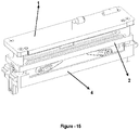
- Cooling device Vacuuming chamber (S1) Opening (S2) Door (S3) Vacuum line (S4) Cap (S5) Vacuum pump (S6) Switch (S7) Stationary plate (1) Movable plate (2) Hole (2a) Guide (3) Carrier chassis (4) Heater (5) Fireproof tape (5a) Insulation element (6) Connection element (7) Blocker plate (8) Housing (9) Arm (10) Sealing member (10a) Actuating member (11) First resilient element (12) Tensioning element (13) Reservoir (14) Actuating shaft (15) Gearwheel (16) Toothed rack (17) Drive element (18) Transmission element (19) Magnetic element (20) Second resilient element (21)
- a vacuuming system developed according to the present invention is suitable for use in at least one vacuuming chamber (S1), having at least one opening (S2) to receive the mouth of a bag to be vacuumed, and being provided in a door (S3) of a cooling device (S) having at least one food preservation compartment and at least one door (S3) which controls access to said compartment,
- the vacuuming system comprising at least one vacuum pump (S6); at least one carrier chassis (4); at least one stationary plate (1) preferably provided in an upper part of said carrier chassis (4); at least one movable plate (2), which is preferably provided between the stationary plate (1) and the carrier chassis (4) and can be moved close to and away from the stationary plate (1), has a closed state in which it contacts with the stationary plate (1) ( Figure 3 ) and an open state in which it does not have any contact with the stationary plate (1), and comprises at least one reservoir (14) (shown in Figure 4 ) in communication with the vacuum pump (S6), wherein a vacuuming operation takes
- a sealing element which when placed in the vacuuming chamber (S1), is provided so as to extend along the edge of the stationary plate (1) and/or the movable plate (2) that is remote to the opening (S2); at least one heater (5), which when placed in the vacuuming chamber (S1), is provided so as to extend along the edge of the stationary plate (1) or the movable plate (2) that is close to the opening (S2), and when the mouth of the bag to be vacuumed is placed into the reservoir (14) and the vacuuming operation is completed with the movable plate (2) assuming its closed state, applies heat to the part of the bag left in the heater so that the bag becomes sealed; at least a first resilient element (12), preferably a sponge, provided on the movable plate (2) or stationary plate (1) against said heater (5), and providing an efficient sealing of the bag; and at least one actuator mechanism, provided in said carrier chassis (4) and providing said movement of the movable plate (2).
- the vacuuming system is placed in the vacuuming chamber (S1) of the cooling device (S), so that the heater (5) and the first resilient element (12) are close to said opening (S2) and the insulation element (6) stays far from said opening (S2).
- the user wants to vacuum a bag containing a foodstuff
- the user places the mouth of the bag into the reservoir (14).
- the vacuuming operation is started so that the movable plate (2) moves towards the stationary plate (1).
- the movable plate (2) assumes its closed state and contacts the stationary plate (1), such that the insulation element (6), the heater (5) and the first resilient element (12) stay in between them.
- the vacuum pump (S6) is activated and the vacuuming operation is effected; following the vacuuming operation, the heater (5) is activated and the bag is closed by means of heat-sealing.
- the vacuuming system comprises at least one blocker plate (8), which is provided between the movable plate (2) and stationary plate (1) so that said reservoir (14) stays between itself (8) and the opening (S2) and becomes aligned with the edge of the reservoir (14) that is remote to the opening (S2), and preferably has a form that extends from the stationary plate (1) to the movable plate (2), and when the mouth of a bag to be vacuumed is to be placed in said reservoir (14), it contacts the mouth of the bag to provide a correct positioning of the mouth; and at least one housing (9), preferably provided on the movable plate (2) to receive the blocker plate (8) in the closed state.
- the user passes the mouth of a bag through said opening (S2) and contacts the mouth of the bag with this blocker plate (8) so as to make sure that the mouth is placed in a correct manner.
- said actuator mechanism comprises at least one guide (3) (preferably at least two guides, passing through the opposed edges of the movable plate (2)), preferably in the form of a shaft, at least one end thereof being connected to the carrier chassis (4), at least the other end thereof being connected to the stationary plate (1), and guiding the movement of the movable plate (2) by being passed through at least one aperture comprised within said movable plate (2); at least one actuating member (11) (preferably at least two actuating members, provided on the opposed edges of the carrier chassis (4)) provided on said carrier chassis (4), being preferably a motor, which has a component that can rotate once it is energized; at least one arm (10) (preferably at least two arms, on the opposed edges of the carrier chassis (44)), preferably in the form of a cam, at least one end thereof being connected to said component of the actuating member (1), at least the other end thereof contacting the movable plate (2), and when said component starts
- the actuator mechanism developed according to this embodiment preferably comprises at least one (preferably at least two) second resilient element (21), at least one end thereof being connected to the carrier chassis (4), at least the other end thereof being connected to the movable plate (2), and in the closed state of the movable plate (2), exerting force to the movable plate (2) so as to move it away from the stationary plate (1), thus providing a more stable transition for the movable plate (2) from the closed state to the open state.
- This second resilient element (21) can be a spring, but can also be made of a shape memory material, which is coupled to an electrical energy source (e.g.
- a control unit of the cooling device, mains supply etc. which, once energized, tends to change size (e.g. shortens) so as to exert force to the movable plate (2) so that it moves away from the stationary plate (1), and which, when the movable plate (2) is moved towards the stationary plate (1), becomes stretched to change size (e.g. elongates).
- said actuator mechanism comprises, preferably, at least one actuating component (15) (in terms of a stable movement, preferably at least four actuating components), made of a shape memory material, which is connected to the carrier chassis (4) from at least one side, and connected to the movable plate (2) from at least the other side, is connected to an electrical energy source (e.g. a control unit of the cooling device, mains supply etc.) and once energized by means of this source, elongates so that the movable plate (2) in the open state assumes its closed state, and once de-energized, shortens so that the movable plate (2) in its closed state assumes its open state.
- an electrical energy source e.g. a control unit of the cooling device, mains supply etc.
- This actuating component (15) can be in the form of a spring, bar, or wire.
- the actuator mechanism developed according to this embodiment preferably comprises at least one guide (3) (preferably at least two guides, passing through the opposed edges of the movable plate (2)), preferably in the form of a shaft, at least one end thereof being connected to the carrier chassis (4), at least the other end thereof being connected to the stationary plate (2), and guiding the movement of the movable plate (2) by being passed through at least one aperture comprised within said movable plate (2).
- the actuator mechanism comprises preferably at least one actuating member (11) (preferably at least two actuating members, provided on the opposed sides of the carrier chassis (4)), being preferably a motor, provided on said carrier chassis (4) and having at least one component which can rotate when energized, and at least one guide (3) (preferably at least two guides, provided on the opposed sides of the movable plate (2)), of which at least one end is connected to said part, and which can rotate around its own axis with said component starting rotating, and is passed through a threaded aperture in the movable plate (2) so that at least the other end thereof is connected to the stationary plate (1), and which is in the form of a shaft with threads on it which match up with the threads in the aperture, and effects said movement of the movable plate (2) when it rotates around its own axis.
- the movable plate (2) can be moved in a gradual manner.
- the actuator mechanism comprises preferably at least one actuating member (11) (preferably at least two actuating members, provided on the opposed sides of the carrier chassis (4)), being preferably a motor, provided on said carrier chassis (4) and having at least one component which can rotate when energized; at least one gearwheel (16) (preferably at least two), which is coupled to said component, and can rotate around an axis when said component rotates, and at least one toothed rack (17) (preferably at least two), of which at least one end is connected to the gearwheel (16), of which at least another end is connected to the movable plate (2), and which converts the rotational motion of the gearwheel (16) into linear motion to effect said movement of the movable plate (2).
- actuating member (11) preferably at least two actuating members, provided on the opposed sides of the carrier chassis (4)
- the actuator mechanism comprises preferably at least one actuating member (11) (preferably at least two actuating members, provided on the opposed sides of the carrier chassis (4)), being preferably a motor, provided on said carrier chassis
- the actuator mechanism preferably comprises at least one drive element (18) (preferably at least two), being preferably a motor, having at least one wheel that can rotate around an axis once energized, and at least one transmission element (19) (preferably at least two transmission elements, i.e. one for each of the drive elements (18)) in the form of a belt, at least one end thereof being connected to said wheel, at least the other end thereof being connected to the movable plate (2), and being wound around the rotating wheel once the drive element is energized, or being released from the wheel without its connection to the wheel being lost, thus converting the rotational motion of the wheel to a linear motion to let the movable plate (2) perform said movement.
- Said drive element (18) is preferably provided on the stationary plate (1).
- the actuator mechanism comprises at least two magnetic elements (20), at least one thereof being provided on the stationary plate (1) and at least the other one thereof on the movable plate (2), in an opposed fashion, having connection to an electrical energy source (e.g.
- a control unit of the cooling device, mains supply, etc. exerting an pulling force onto each other once energized by said source, thus enabling the movable plate (2) to move and assume its closed state, wherein upon deactivation of the energy supply, the exerted force is removed, and by this way, the movable plate (2) is enabled to move and assume its open state; and at least one guide (3) (preferably at least two guides on the opposed edges of the movable plate (2)), being preferably in the form of a shaft, at least one end thereof being connected to the carrier chassis (4), at least the other end thereof being connected to the stationary plate (1), and being passed through at least one aperture comprised in said movable plate (2), thereby guiding the movement of the movable plate (2).
- at least one guide (3) preferably at least two guides on the opposed edges of the movable plate (2)
- the movable plate (2) is enabled to effect a silent motion.
- Said actuator mechanism according to this embodiment preferably further comprises at least a second resilient element (21) (e.g. a spring) (preferably at least two second resilient elements), at least one end thereof being connected to the carrier chassis (4), and at least the other end thereof to the movable plate (2), and in the closed state of the movable plate (2), exerting force to the movable plate (2) so as to move it away from the stationary plate (1), thus providing a more stable transition for the movable plate (2) from the closed state to the open state.
- a second resilient element (21) e.g. a spring
- the movable plate (2) preferably at least two second resilient elements
- said movable plate (2) and stationary plate (1) are provided with a certain inclination with respect to the carrier chassis (4).
- the mouth of a bag to be vacuumed can be provided in the reservoir (14) in a more efficient manner.
- the vacuuming system developed according to another alternative embodiment preferably comprises at least one tensioning element (13) (e.g. a screw), being connected to said heater (5), enabling to bring the heater (5) to a stretched state so that the bag can be properly subjected to heat-sealing.
- the heater (5) is fixed from one of its sides to the stationary plate (1) or to the movable plate (2), and from its other side, to the tensioning element (13).
- tightening the tensioning element (13) will bring the heater (5) to a stretched state, such that air leakage into the mouth of the bag is prevented and an efficient vacuuming system is achieved.
- the vacuuming system comprises at least one fireproof tape (5a) provided on the heater (5), preventing an instant burning of the bag due to the heat of the heater (5), and transferring the heat of the heater (5) to the bag.
- the vacuuming system developed in a further exemplary embodiment of the present invention preferably comprises at least one switch (S7), measuring the amount of vacuum within said reservoir (14), and once the measured value of vacuum reaches a predetermined value, deactivating the vacuum pump (S6) and activating the heater (5).
- S7 at least one switch
- S6 deactivating the vacuum pump
- S6 activating the heater (5).
- the vacuuming system developed in a further preferred embodiment preferably comprises at least one warning device, alerting the respective user in relation to a vacuuming operation.
- This warning device can provide visual and/or aural alerts.
- the warning device preferably comprises more than one light source (e.g. LEDs) to inform / warn the respective user visually.
- the vacuuming system preferably comprises a data input device having at least a first control element to initiate a vacuuming operation.
- the respective user can initiate the vacuuming operation after the user places the mouth of a bag into the reservoir (14).
- Said data input device can preferably further enable a user to determine the amount of vacuum to be generated in the reservoir (14), and can comprise at least a second control element for this purpose.
- the amount of vacuum to be generated in the reservoir (14) can be directly determined, but the desired amount of vacuum in the reservoir (14) can also be adjusted by selecting the size and/or type of a bag.
- foods having different hardness can be vacuumed using differing vacuum values so as to achieve a more efficient vacuuming system.
- said data input device can also preferably be used to seal the mouth of a bag without performing a vacuuming operation and comprises at least a third control element for this purpose.
- the third control element When a user uses the third control element, the movable plate (2) comes closer to the stationary plate (1) and the vacuuming system directly energizes the heater (5) without activating the vacuum pump (S6). Thus, a more effective vacuuming system is achieved.
- said vacuum pump (S6) is provided on the movable plate (2) so as to be in communication with said reservoir (14).
- the vacuum pump (S6) is provided on the carrier chassis (4), wherein the vacuuming system according to this embodiment preferably comprises at least one vacuum line (S4) (e.g. a hose), providing communication between the vacuum pump (S6) and said reservoir (14), and one end thereof being connected to the vacuum pump (S6), and the other end thereof opening to said reservoir (14).
- S4 e.g. a hose
- the vacuuming system developed according to another preferred embodiment of the present invention comprises at least one hole (2a) in the movable plate (2) in a region where said reservoir (14) is provided, and at least one adjustment element, closing said hole (2a) during a vacuuming operation, and after the vacuuming operation is completed, opening the hole (2a) to allow airflow through the hole (2a) to provide an easy removal of the movable plate (2) from the stationary plate (1).
- This adjustment element can be in the form of a valve.
- the actuator mechanism comprises an arm (10)
- said hole (2a) is provided in the part of the movable plate (2) to which this arm (10) contacts, wherein a sealing member (10a) is provided on the part of the arm (10) that contacts at least to the movable plate (2). It is thus practically enabled to close the hole (2a) during vacuuming, and open the hole (2a) by a movement of the arm (10) once a vacuuming operation is completed.
- the vacuuming system developed according to another alternative embodiment of the present invention preferably comprises at least one temperature sensor measuring the temperature of said heater (5).
- the temperature of the heater (5) is measured by means of said temperature sensor and is transmitted to a control unit to be compared with a predetermined value.
- the heater (5) is prevented from punching or tearing a bag because of getting overheated, as may be the case when the vacuuming system is activated again and again.
- the vacuuming system developed according to another exemplary embodiment preferably comprises at least one cutting element, capable of moving along the edge of the stationary plate (1) or the movable plate (2) that is close to said opening (S2) to put out a foodstuff from a vacuumed and heat-sealed bag.
- the vacuuming system also preferably comprises at least one pushing member, pushing any remaining part of the bag out through the opening (S2) so that no part of a cut bag remains in the vacuuming system.
- the surface of said movable plate (2) facing the stationary plate (1) has an inclined structure and comprises at least one outlet hole and at least one outlet valve opening and closing said hole at its tip part that is remote to the stationary plate (1).
- the vacuuming system preferably comprises at least one fluid collection member that is in communication with said outlet hole. This fluid collection member can be in the form of a tube, guiding the juice of a food to any desired target, or may be in the form of a container in which the juice is collected.
- said inclined surface is preferably provided with a layer made of a dirt- and liquid-repellent (e.g. hydrophobic) material.
- the vacuuming system preferably comprises at least one dirt sensor to prevent dirt emerging from the juice of foods giving rise to an obstruction in the system.
- the vacuuming system also preferably comprises at least one transmission line, one end thereof being connected to a water source (e.g.
- a water dispenser comprised in the respective cooling device), and the other end thereof becoming opened to said surface of said movable plate (2) so as to transfer water from the source to said surface, and at least one valve, in communication with said dirt sensor, controlling water flow through the transmission line according to the value measured by the dirt sensor.
- An operation method for the vacuuming system developed according to the present invention comprises the steps of determining by the user an operation (e.g. vacuuming, sealing, cutting, cleaning etc.) to be performed using the vacuuming system, and positioning a bag to the vacuuming system so that the mouth of the bag is placed in said reservoir (14); if the operation determined is vacuuming, sealing, or cutting, moving the movable plate (2) by means of said actuator mechanism so as to come close to the stationary plate (1) and clamping the bag between the movable plate (2) and the stationary plate (1); if the operation determined is vacuuming and when the movable plate (2) assumes its closed state, generating a vacuum medium in said reservoir (14) by energizing the vacuum pump (S6), and meanwhile, evacuating the air out of the bag through the mouth of the bag placed in the reservoir (14) so that a target vacuum value in the reservoir (14) is achieved; once vacuuming is completed, or if the operation determined is sealing, energizing the heater (5) and heat-sealing the bag;
- the vacuuming operation can be effected for a first time period, or can be effected until the vacuum value in the reservoir (14) reaches a user-determined vacuum value (e.g. 0,50 to 0,05 bar interval). In another embodiment, the vacuuming operation can be effected until a vacuum value is reached that matches the size and/or the type of a bag selected by the user by means of a data input device.
- a user-determined vacuum value e.g. 0,50 to 0,05 bar interval
- the method according to the present invention preferably comprises the steps of measuring the vacuum value in the reservoir (14) by at least one switch (S7) and transmitting it to a control unit; comparing the measured value with a target vacuum value saved in the control unit (the target vacuum value is a value determined by the user and/or a value correlating with the size and type of the bag); and once the measured value reaches the target value, stopping the vacuum pump (S6).
- the sealing operation can be effected for a second time period, or can be effected until a temperature value of the heater (5), as measured using a temperature sensor, reaches a first threshold temperature value.
- This first threshold temperature value is preferably a value saved in a control unit according to the type of the bag that is used.
- Another preferred embodiment of the method according to the present invention comprises the steps of measuring the temperature of said heater (5) prior to a vacuuming operation by means of a temperature sensor; comparing the measured temperature value to a second threshold temperature value (e.g. 55°C); if the measured value is higher than the second threshold temperature value, not initiating the vacuuming operation, and if the measured value is lower than the second threshold temperature value, initiating the vacuuming operation.
- Said second threshold temperature value is preferably a temperature value, at which the bag does not burn and melt, and which is correlated to the type of bag selected by the user.
- the method according to this embodiment further comprises the steps of determining a maximum time period for which the heater (5) can be operated in line with the difference between the measured temperature value and the second threshold temperature value when the measured temperature value is lower than the second threshold temperature value, and deactivating the heater (5) at the completion of this maximum time period.
- the method according to another preferred embodiment of the present invention comprises the step of waiting for a second period of time, after the user determines the operation and if the determined operation is vacuuming, sealing, or cutting; and moving the movable plate (2) at the end of this second time period.
- the time period required by the user to correctly place the mouth of bag into the reservoir (14) is provided.
- the method according to another preferred embodiment comprises the steps of alerting the user if a target vacuum value in the reservoir (14) cannot be reached in a third time period, and terminating the vacuuming operation.
- a target vacuum value cannot be reached in said reservoir (14) as the air present in the bag cannot be evacuated.
- the user will be alerted to provide a reliable operation method.
- the method according to another alternative embodiment of the present invention preferably comprises the step of controlling by a control unit the amount of current drawn by the vacuum pump (S6) to detect if or not the vacuum value in the reservoir (14) reached a target vacuum value.
- a control unit For each vacuum value provided by the vacuum pump (S6), there is provided a different current value. These values can be determined by the user, but they can also be determined during the manufacture of the vacuuming system. When these values are saved in the control unit, the current value drawn by the vacuum pump (S6) during vacuuming is measured and compared to the values saved in the control unit, and the vacuum value corresponding to the measured current value can be determined and it can be easily and practically determined if or not the determined vacuum value is equivalent to the target vacuum value.
- the method according to another preferred embodiment comprises the steps of measuring the dirt level of the movable plate (2) and/or the stationary plate (1) by at least one dirt sensor; and alerting the user when the dirt level reaches a threshold dirt value.
- the method according to this embodiment further comprises the step of automatically cleaning the movable plate (2) with water fed from a water source, when the dirt level equals to or is higher than the threshold dirt value. It is thus ensured that the vacuuming system is always kept clean and a system that operates independently of its user is achieved.
- a cooling device (S) developed according to the present invention comprises at least one food preservation compartment in which foodstuff is preserved under a certain temperature value, and at least one door (S3), controlling access to said compartment, and having an open state giving access to, and a closed state preventing access to said compartment.
- the cooling device (S) according to the present invention further comprises at least one vacuuming chamber (S1) provided in said door (S3), and having at least one opening (S2) providing access into its interior in the closed or open state of door (S3); and at least one said vacuuming system provided in the vacuuming chamber (S1).
- the vacuum pump (S6) and switch (S7) comprised by the vacuuming system are provided in a cap (S5) of the door (S3) of the cooling device (S).
- the cooling device (S) further comprises at least one vacuum line (S4) (e.g. a hose), at least one end thereof being connected to the vacuum pump (S6) and at least the other end thereof opening into said reservoir (14) for a vacuuming operation.
- said vacuum line (S4) In order to make said vacuum line (S4) open into the reservoir (14), its connection to the vacuuming system is preferably carried out by means of at least one connection element (7) provided in the stationary plate (1).
- the cooling device (S) comprises at least one sensor measuring the current and/or voltage instantaneously drawn by the cooling device (S), and at least one control unit, which is in connection with the sensor, compares the values measured by the sensor to a threshold standard value saved in itself, and as a result of this comparison, determines the difference between the value measured by the sensor and the threshold standard value on a percent basis, and if the measured value is higher than the threshold standard value, shortens the running time of the heater (5) according to this difference (e.g. up to this percentage difference), and if the measured value is lower than the threshold standard value, increases the running time of the heater (5) according to this difference (e.g. up to this percentage difference).
- the cooling device (S) and the vacuuming system are connected to a common energy supply under normal operation conditions, when the energy drawn by the cooling device (S) increases, the amount of energy drawn by the vacuuming system increases too, therefore leading to a similar increase in the operation power of the heater (5). As a result of this increase, a bag can burn and melt down during a sealing operation. In order to prevent this situation, this embodiment enables to shorten the running time of the heater (5). Similarly, if the amount of energy drawn by the cooling device (S) drops down, the operation power of the vacuuming system and therefore the heater (5) becomes lower. This, in turn, may cause an inadequate heating and sealing of the bag during a heat-sealing operation, so that the running time of the heater (5) is prolonged to eliminate any failures.
- the preservation time of foods in household use can be prolonged in an efficient and practical manner. Additionally, a correct placement and a smooth sealing are provided for the bag so that any air leak into the bag is avoided and a safe vacuuming system is achieved. Furthermore, by virtue of the cooling device (S) according to the present invention, consumers are enabled to perform an easy and practical vacuuming operation whenever they need to do so, and the need for an external device for vacuuming is avoided.
Landscapes
- Engineering & Computer Science (AREA)
- Chemical & Material Sciences (AREA)
- Mechanical Engineering (AREA)
- Combustion & Propulsion (AREA)
- Physics & Mathematics (AREA)
- Thermal Sciences (AREA)
- General Engineering & Computer Science (AREA)
- Dispersion Chemistry (AREA)
- Vacuum Packaging (AREA)
Applications Claiming Priority (1)
| Application Number | Priority Date | Filing Date | Title |
|---|---|---|---|
| TR2017/12977A TR201712977A2 (tr) | 2017-08-29 | 2017-08-29 | Bir gida poşeti vakumlama sistemi, çalişma yöntemi ve bunlari içeren bir soğutucu cihaz. |
Publications (2)
| Publication Number | Publication Date |
|---|---|
| EP3450893A1 true EP3450893A1 (de) | 2019-03-06 |
| EP3450893B1 EP3450893B1 (de) | 2022-08-24 |
Family
ID=63209182
Family Applications (1)
| Application Number | Title | Priority Date | Filing Date |
|---|---|---|---|
| EP18186132.9A Active EP3450893B1 (de) | 2017-08-29 | 2018-07-27 | Kühlvorrichtung mit nahrungsmittelbeutelvakuumsystem, und betriebsverfahren |
Country Status (2)
| Country | Link |
|---|---|
| EP (1) | EP3450893B1 (de) |
| TR (1) | TR201712977A2 (de) |
Cited By (41)
| Publication number | Priority date | Publication date | Assignee | Title |
|---|---|---|---|---|
| CN111578585A (zh) * | 2020-04-26 | 2020-08-25 | 海信(山东)冰箱有限公司 | 冰箱 |
| CN111765695A (zh) * | 2020-07-01 | 2020-10-13 | 海信(山东)冰箱有限公司 | 冰箱 |
| CN111765696A (zh) * | 2020-07-01 | 2020-10-13 | 海信(山东)冰箱有限公司 | 冰箱 |
| CN111765694A (zh) * | 2020-07-01 | 2020-10-13 | 海信(山东)冰箱有限公司 | 冰箱 |
| CN111765697A (zh) * | 2020-07-01 | 2020-10-13 | 海信(山东)冰箱有限公司 | 冰箱 |
| CN111765698A (zh) * | 2020-07-01 | 2020-10-13 | 海信(山东)冰箱有限公司 | 冰箱 |
| CN111765689A (zh) * | 2020-07-01 | 2020-10-13 | 海信(山东)冰箱有限公司 | 冰箱 |
| CN111765693A (zh) * | 2020-07-01 | 2020-10-13 | 海信(山东)冰箱有限公司 | 冰箱 |
| CN111765690A (zh) * | 2020-07-01 | 2020-10-13 | 海信(山东)冰箱有限公司 | 冰箱 |
| CN111998597A (zh) * | 2019-05-27 | 2020-11-27 | 海信(山东)冰箱有限公司 | 一种冰箱 |
| CN111998593A (zh) * | 2019-05-27 | 2020-11-27 | 海信(山东)冰箱有限公司 | 一种冰箱 |
| CN111998599A (zh) * | 2019-05-27 | 2020-11-27 | 海信(山东)冰箱有限公司 | 一种冰箱 |
| CN111998594A (zh) * | 2019-05-27 | 2020-11-27 | 海信(山东)冰箱有限公司 | 一种冰箱 |
| CN111998596A (zh) * | 2019-05-27 | 2020-11-27 | 海信(山东)冰箱有限公司 | 一种冰箱 |
| CN111998598A (zh) * | 2019-05-27 | 2020-11-27 | 海信(山东)冰箱有限公司 | 一种冰箱 |
| CN111998595A (zh) * | 2019-05-27 | 2020-11-27 | 海信(山东)冰箱有限公司 | 一种冰箱 |
| CN112284003A (zh) * | 2019-07-24 | 2021-01-29 | 海信(山东)冰箱有限公司 | 一种冰箱 |
| CN112284001A (zh) * | 2019-07-24 | 2021-01-29 | 海信(山东)冰箱有限公司 | 一种冰箱 |
| CN112284002A (zh) * | 2019-07-24 | 2021-01-29 | 海信(山东)冰箱有限公司 | 一种冰箱 |
| CN112303976A (zh) * | 2019-07-24 | 2021-02-02 | 海信(山东)冰箱有限公司 | 一种冰箱 |
| CN112303977A (zh) * | 2019-07-24 | 2021-02-02 | 海信(山东)冰箱有限公司 | 一种冰箱 |
| CN112393515A (zh) * | 2019-08-16 | 2021-02-23 | 海信(山东)冰箱有限公司 | 一种冰箱 |
| CN112393518A (zh) * | 2019-08-16 | 2021-02-23 | 海信(山东)冰箱有限公司 | 一种具有真空封装装置的冰箱 |
| CN112577241A (zh) * | 2019-09-30 | 2021-03-30 | 海信(山东)冰箱有限公司 | 一种冰箱 |
| CN112577240A (zh) * | 2019-09-30 | 2021-03-30 | 海信(山东)冰箱有限公司 | 一种冰箱 |
| CN112577242A (zh) * | 2019-09-30 | 2021-03-30 | 海信(山东)冰箱有限公司 | 一种冰箱 |
| CN112577238A (zh) * | 2019-09-30 | 2021-03-30 | 海信(山东)冰箱有限公司 | 一种冰箱 |
| CN112577243A (zh) * | 2019-09-30 | 2021-03-30 | 海信(山东)冰箱有限公司 | 一种冰箱 |
| CN112577239A (zh) * | 2019-09-30 | 2021-03-30 | 海信(山东)冰箱有限公司 | 一种冰箱 |
| CN112781293A (zh) * | 2019-11-04 | 2021-05-11 | 海信(山东)冰箱有限公司 | 一种冰箱 |
| CN113375391A (zh) * | 2020-03-09 | 2021-09-10 | 海信(山东)冰箱有限公司 | 一种冰箱 |
| CN113375390A (zh) * | 2020-03-09 | 2021-09-10 | 海信(山东)冰箱有限公司 | 一种冰箱 |
| CN113531990A (zh) * | 2020-04-17 | 2021-10-22 | 海信(山东)冰箱有限公司 | 冰箱 |
| CN113623922A (zh) * | 2020-05-08 | 2021-11-09 | 海信(山东)冰箱有限公司 | 冰箱 |
| CN113883789A (zh) * | 2020-07-01 | 2022-01-04 | 海信(山东)冰箱有限公司 | 冰箱及其控制方法 |
| WO2022022087A1 (zh) * | 2020-07-31 | 2022-02-03 | 海信(山东)冰箱有限公司 | 一种冰箱 |
| WO2022033149A1 (zh) * | 2020-08-14 | 2022-02-17 | 海信(山东)冰箱有限公司 | 一种冰箱 |
| CN114061223A (zh) * | 2020-08-10 | 2022-02-18 | 海信(山东)冰箱有限公司 | 一种冰箱及管路安装方法 |
| EP4026780A1 (de) | 2021-01-07 | 2022-07-13 | Vestel Elektronik Sanayi ve Ticaret A.S. | Selbstreparierende vakuumvorrichtung |
| EP3978849A4 (de) * | 2019-05-27 | 2023-05-31 | Hisense (shandong) Refrigerator Co., Ltd. | Kühlschrank |
| EP4148351B1 (de) * | 2020-05-08 | 2025-12-31 | Hisense Refrigerator Co., Ltd. | Kühlschrank |
Citations (5)
| Publication number | Priority date | Publication date | Assignee | Title |
|---|---|---|---|---|
| JPH09288765A (ja) * | 1996-04-22 | 1997-11-04 | Watanabe Norio | 温度調節付自動販売機用コントロール装置 |
| US20060230711A1 (en) * | 2003-07-31 | 2006-10-19 | Jcs/Thg, Llc | Vacuum packaging appliance |
| WO2012174339A2 (en) * | 2011-06-17 | 2012-12-20 | Sunbeam Products, Inc. | Automated food saver machine |
| US8438870B2 (en) | 2008-02-06 | 2013-05-14 | Whirlpool Corporation | Refrigerator door vacuum preservation system |
| CN106895650A (zh) * | 2017-01-24 | 2017-06-27 | 青岛海高设计制造有限公司 | 抽真空密封装置及具有该抽真空密封装置的冰箱 |
-
2017
- 2017-08-29 TR TR2017/12977A patent/TR201712977A2/tr unknown
-
2018
- 2018-07-27 EP EP18186132.9A patent/EP3450893B1/de active Active
Patent Citations (5)
| Publication number | Priority date | Publication date | Assignee | Title |
|---|---|---|---|---|
| JPH09288765A (ja) * | 1996-04-22 | 1997-11-04 | Watanabe Norio | 温度調節付自動販売機用コントロール装置 |
| US20060230711A1 (en) * | 2003-07-31 | 2006-10-19 | Jcs/Thg, Llc | Vacuum packaging appliance |
| US8438870B2 (en) | 2008-02-06 | 2013-05-14 | Whirlpool Corporation | Refrigerator door vacuum preservation system |
| WO2012174339A2 (en) * | 2011-06-17 | 2012-12-20 | Sunbeam Products, Inc. | Automated food saver machine |
| CN106895650A (zh) * | 2017-01-24 | 2017-06-27 | 青岛海高设计制造有限公司 | 抽真空密封装置及具有该抽真空密封装置的冰箱 |
Cited By (48)
| Publication number | Priority date | Publication date | Assignee | Title |
|---|---|---|---|---|
| CN111998597A (zh) * | 2019-05-27 | 2020-11-27 | 海信(山东)冰箱有限公司 | 一种冰箱 |
| CN111998599B (zh) * | 2019-05-27 | 2025-06-27 | 海信冰箱有限公司 | 一种冰箱 |
| EP3978849A4 (de) * | 2019-05-27 | 2023-05-31 | Hisense (shandong) Refrigerator Co., Ltd. | Kühlschrank |
| CN111998595A (zh) * | 2019-05-27 | 2020-11-27 | 海信(山东)冰箱有限公司 | 一种冰箱 |
| CN111998598A (zh) * | 2019-05-27 | 2020-11-27 | 海信(山东)冰箱有限公司 | 一种冰箱 |
| CN111998596A (zh) * | 2019-05-27 | 2020-11-27 | 海信(山东)冰箱有限公司 | 一种冰箱 |
| CN111998594A (zh) * | 2019-05-27 | 2020-11-27 | 海信(山东)冰箱有限公司 | 一种冰箱 |
| CN111998599A (zh) * | 2019-05-27 | 2020-11-27 | 海信(山东)冰箱有限公司 | 一种冰箱 |
| CN111998593A (zh) * | 2019-05-27 | 2020-11-27 | 海信(山东)冰箱有限公司 | 一种冰箱 |
| CN112284001A (zh) * | 2019-07-24 | 2021-01-29 | 海信(山东)冰箱有限公司 | 一种冰箱 |
| CN112284003A (zh) * | 2019-07-24 | 2021-01-29 | 海信(山东)冰箱有限公司 | 一种冰箱 |
| CN112284002A (zh) * | 2019-07-24 | 2021-01-29 | 海信(山东)冰箱有限公司 | 一种冰箱 |
| CN112303976A (zh) * | 2019-07-24 | 2021-02-02 | 海信(山东)冰箱有限公司 | 一种冰箱 |
| CN112303977A (zh) * | 2019-07-24 | 2021-02-02 | 海信(山东)冰箱有限公司 | 一种冰箱 |
| CN112393515A (zh) * | 2019-08-16 | 2021-02-23 | 海信(山东)冰箱有限公司 | 一种冰箱 |
| CN112393518A (zh) * | 2019-08-16 | 2021-02-23 | 海信(山东)冰箱有限公司 | 一种具有真空封装装置的冰箱 |
| CN112577240A (zh) * | 2019-09-30 | 2021-03-30 | 海信(山东)冰箱有限公司 | 一种冰箱 |
| CN112577241A (zh) * | 2019-09-30 | 2021-03-30 | 海信(山东)冰箱有限公司 | 一种冰箱 |
| CN112577242B (zh) * | 2019-09-30 | 2025-06-27 | 海信冰箱有限公司 | 一种冰箱 |
| CN112577239B (zh) * | 2019-09-30 | 2025-06-27 | 海信冰箱有限公司 | 一种冰箱 |
| CN112577240B (zh) * | 2019-09-30 | 2025-06-27 | 海信冰箱有限公司 | 一种冰箱 |
| CN112577241B (zh) * | 2019-09-30 | 2025-06-27 | 海信冰箱有限公司 | 一种冰箱 |
| CN112577239A (zh) * | 2019-09-30 | 2021-03-30 | 海信(山东)冰箱有限公司 | 一种冰箱 |
| CN112577243A (zh) * | 2019-09-30 | 2021-03-30 | 海信(山东)冰箱有限公司 | 一种冰箱 |
| CN112577238A (zh) * | 2019-09-30 | 2021-03-30 | 海信(山东)冰箱有限公司 | 一种冰箱 |
| CN112577242A (zh) * | 2019-09-30 | 2021-03-30 | 海信(山东)冰箱有限公司 | 一种冰箱 |
| CN112781293A (zh) * | 2019-11-04 | 2021-05-11 | 海信(山东)冰箱有限公司 | 一种冰箱 |
| CN113375390A (zh) * | 2020-03-09 | 2021-09-10 | 海信(山东)冰箱有限公司 | 一种冰箱 |
| CN113375391A (zh) * | 2020-03-09 | 2021-09-10 | 海信(山东)冰箱有限公司 | 一种冰箱 |
| CN113531990A (zh) * | 2020-04-17 | 2021-10-22 | 海信(山东)冰箱有限公司 | 冰箱 |
| CN111578585A (zh) * | 2020-04-26 | 2020-08-25 | 海信(山东)冰箱有限公司 | 冰箱 |
| CN113623922A (zh) * | 2020-05-08 | 2021-11-09 | 海信(山东)冰箱有限公司 | 冰箱 |
| EP4148351B1 (de) * | 2020-05-08 | 2025-12-31 | Hisense Refrigerator Co., Ltd. | Kühlschrank |
| CN111765698A (zh) * | 2020-07-01 | 2020-10-13 | 海信(山东)冰箱有限公司 | 冰箱 |
| CN111765695A (zh) * | 2020-07-01 | 2020-10-13 | 海信(山东)冰箱有限公司 | 冰箱 |
| CN113883789A (zh) * | 2020-07-01 | 2022-01-04 | 海信(山东)冰箱有限公司 | 冰箱及其控制方法 |
| CN111765690A (zh) * | 2020-07-01 | 2020-10-13 | 海信(山东)冰箱有限公司 | 冰箱 |
| CN111765693A (zh) * | 2020-07-01 | 2020-10-13 | 海信(山东)冰箱有限公司 | 冰箱 |
| CN111765689A (zh) * | 2020-07-01 | 2020-10-13 | 海信(山东)冰箱有限公司 | 冰箱 |
| CN111765694A (zh) * | 2020-07-01 | 2020-10-13 | 海信(山东)冰箱有限公司 | 冰箱 |
| CN111765696A (zh) * | 2020-07-01 | 2020-10-13 | 海信(山东)冰箱有限公司 | 冰箱 |
| CN111765697A (zh) * | 2020-07-01 | 2020-10-13 | 海信(山东)冰箱有限公司 | 冰箱 |
| CN111765696B (zh) * | 2020-07-01 | 2021-08-20 | 海信(山东)冰箱有限公司 | 冰箱 |
| WO2022022087A1 (zh) * | 2020-07-31 | 2022-02-03 | 海信(山东)冰箱有限公司 | 一种冰箱 |
| CN114061223B (zh) * | 2020-08-10 | 2023-04-14 | 海信冰箱有限公司 | 一种冰箱及管路安装方法 |
| CN114061223A (zh) * | 2020-08-10 | 2022-02-18 | 海信(山东)冰箱有限公司 | 一种冰箱及管路安装方法 |
| WO2022033149A1 (zh) * | 2020-08-14 | 2022-02-17 | 海信(山东)冰箱有限公司 | 一种冰箱 |
| EP4026780A1 (de) | 2021-01-07 | 2022-07-13 | Vestel Elektronik Sanayi ve Ticaret A.S. | Selbstreparierende vakuumvorrichtung |
Also Published As
| Publication number | Publication date |
|---|---|
| EP3450893B1 (de) | 2022-08-24 |
| TR201712977A2 (tr) | 2019-03-21 |
Similar Documents
| Publication | Publication Date | Title |
|---|---|---|
| EP3450893A1 (de) | Nahrungsmittelbeutelvakuumsystem, betriebsverfahren dafür und kühlvorrichtung damit | |
| EP2768736B1 (de) | Vakuumverpackungs- und verschlussvorrichtung mit doppelversiegelung | |
| JP5714120B2 (ja) | 封止温度を制御するアルゴリズムを有する加熱封止装置 | |
| US20190000272A1 (en) | Cooking device | |
| US9676506B2 (en) | Vacuum packaging and sealing appliance with liquid detection | |
| EP2000741A2 (de) | Vakuumkochvorrichtung für den Haushaltsgebrauch | |
| US9457920B2 (en) | Automated food saver machine | |
| US20150027089A1 (en) | Vacuum Packaging and Sealing Appliance with Cooling Fan | |
| US11753196B2 (en) | Vacuum sealer and method of sealing same | |
| KR100781674B1 (ko) | 전기압력밥솥 및 이의 제어방법 | |
| EP1395087A3 (de) | Mit Heizern ausgerüstete Kochvorrichtung und Verfahren zur Steuerung dergleichen | |
| JP2018121757A (ja) | 加熱調理器 | |
| WO2014190055A2 (en) | Dual heat strip and removable tray for a vacuum sealing machine | |
| FR2965331A1 (fr) | Procede de commande en fonctionnement d'un four de cuisson et four de cuisson associe | |
| KR101710039B1 (ko) | 개폐형 인덕션 가열부를 가지는 즉석식품 가열조리장치 | |
| EP3009255B1 (de) | Vakuumverpackungs- und siegelvorrichtung mit kühlgebläse | |
| KR101819222B1 (ko) | 즉석식품 가열조리장치 | |
| KR101710036B1 (ko) | 개폐형 스팀 가열부를 가지는 즉석식품 가열조리장치 | |
| KR101819224B1 (ko) | 승강식 스팀노즐을 가지는 즉석식품 가열조리장치 | |
| CN113915816B (zh) | 冰箱及其真空封装方法 | |
| KR20200097469A (ko) | 회전식 압착수단을 구비한 액상추출장치 | |
| CN113915814B (zh) | 冰箱及其真空封装方法 | |
| CN120052404A (zh) | 解冻装置及具有其的烹饪装置 | |
| CN114104390B (zh) | 冰箱的真空封装方法及冰箱 | |
| KR101819223B1 (ko) | 승강식 온수노즐을 가지는 즉석식품 가열조리장치 |
Legal Events
| Date | Code | Title | Description |
|---|---|---|---|
| PUAI | Public reference made under article 153(3) epc to a published international application that has entered the european phase |
Free format text: ORIGINAL CODE: 0009012 |
|
| STAA | Information on the status of an ep patent application or granted ep patent |
Free format text: STATUS: THE APPLICATION HAS BEEN PUBLISHED |
|
| AK | Designated contracting states |
Kind code of ref document: A1 Designated state(s): AL AT BE BG CH CY CZ DE DK EE ES FI FR GB GR HR HU IE IS IT LI LT LU LV MC MK MT NL NO PL PT RO RS SE SI SK SM TR |
|
| AX | Request for extension of the european patent |
Extension state: BA ME |
|
| STAA | Information on the status of an ep patent application or granted ep patent |
Free format text: STATUS: REQUEST FOR EXAMINATION WAS MADE |
|
| 17P | Request for examination filed |
Effective date: 20190905 |
|
| RBV | Designated contracting states (corrected) |
Designated state(s): AL AT BE BG CH CY CZ DE DK EE ES FI FR GB GR HR HU IE IS IT LI LT LU LV MC MK MT NL NO PL PT RO RS SE SI SK SM TR |
|
| STAA | Information on the status of an ep patent application or granted ep patent |
Free format text: STATUS: EXAMINATION IS IN PROGRESS |
|
| 17Q | First examination report despatched |
Effective date: 20201012 |
|
| GRAP | Despatch of communication of intention to grant a patent |
Free format text: ORIGINAL CODE: EPIDOSNIGR1 |
|
| STAA | Information on the status of an ep patent application or granted ep patent |
Free format text: STATUS: GRANT OF PATENT IS INTENDED |
|
| INTG | Intention to grant announced |
Effective date: 20220323 |
|
| GRAS | Grant fee paid |
Free format text: ORIGINAL CODE: EPIDOSNIGR3 |
|
| GRAA | (expected) grant |
Free format text: ORIGINAL CODE: 0009210 |
|
| STAA | Information on the status of an ep patent application or granted ep patent |
Free format text: STATUS: THE PATENT HAS BEEN GRANTED |
|
| AK | Designated contracting states |
Kind code of ref document: B1 Designated state(s): AL AT BE BG CH CY CZ DE DK EE ES FI FR GB GR HR HU IE IS IT LI LT LU LV MC MK MT NL NO PL PT RO RS SE SI SK SM TR |
|
| REG | Reference to a national code |
Ref country code: CH Ref legal event code: EP |
|
| REG | Reference to a national code |
Ref country code: DE Ref legal event code: R096 Ref document number: 602018039616 Country of ref document: DE |
|
| REG | Reference to a national code |
Ref country code: IE Ref legal event code: FG4D |
|
| REG | Reference to a national code |
Ref country code: AT Ref legal event code: REF Ref document number: 1513922 Country of ref document: AT Kind code of ref document: T Effective date: 20220915 |
|
| REG | Reference to a national code |
Ref country code: LT Ref legal event code: MG9D |
|
| REG | Reference to a national code |
Ref country code: NL Ref legal event code: MP Effective date: 20220824 |
|
| PG25 | Lapsed in a contracting state [announced via postgrant information from national office to epo] |
Ref country code: SE Free format text: LAPSE BECAUSE OF FAILURE TO SUBMIT A TRANSLATION OF THE DESCRIPTION OR TO PAY THE FEE WITHIN THE PRESCRIBED TIME-LIMIT Effective date: 20220824 Ref country code: RS Free format text: LAPSE BECAUSE OF FAILURE TO SUBMIT A TRANSLATION OF THE DESCRIPTION OR TO PAY THE FEE WITHIN THE PRESCRIBED TIME-LIMIT Effective date: 20220824 Ref country code: PT Free format text: LAPSE BECAUSE OF FAILURE TO SUBMIT A TRANSLATION OF THE DESCRIPTION OR TO PAY THE FEE WITHIN THE PRESCRIBED TIME-LIMIT Effective date: 20221226 Ref country code: NO Free format text: LAPSE BECAUSE OF FAILURE TO SUBMIT A TRANSLATION OF THE DESCRIPTION OR TO PAY THE FEE WITHIN THE PRESCRIBED TIME-LIMIT Effective date: 20221124 Ref country code: NL Free format text: LAPSE BECAUSE OF FAILURE TO SUBMIT A TRANSLATION OF THE DESCRIPTION OR TO PAY THE FEE WITHIN THE PRESCRIBED TIME-LIMIT Effective date: 20220824 Ref country code: LV Free format text: LAPSE BECAUSE OF FAILURE TO SUBMIT A TRANSLATION OF THE DESCRIPTION OR TO PAY THE FEE WITHIN THE PRESCRIBED TIME-LIMIT Effective date: 20220824 Ref country code: LT Free format text: LAPSE BECAUSE OF FAILURE TO SUBMIT A TRANSLATION OF THE DESCRIPTION OR TO PAY THE FEE WITHIN THE PRESCRIBED TIME-LIMIT Effective date: 20220824 Ref country code: FI Free format text: LAPSE BECAUSE OF FAILURE TO SUBMIT A TRANSLATION OF THE DESCRIPTION OR TO PAY THE FEE WITHIN THE PRESCRIBED TIME-LIMIT Effective date: 20220824 |
|
| REG | Reference to a national code |
Ref country code: AT Ref legal event code: MK05 Ref document number: 1513922 Country of ref document: AT Kind code of ref document: T Effective date: 20220824 |
|
| PG25 | Lapsed in a contracting state [announced via postgrant information from national office to epo] |
Ref country code: PL Free format text: LAPSE BECAUSE OF FAILURE TO SUBMIT A TRANSLATION OF THE DESCRIPTION OR TO PAY THE FEE WITHIN THE PRESCRIBED TIME-LIMIT Effective date: 20220824 Ref country code: IS Free format text: LAPSE BECAUSE OF FAILURE TO SUBMIT A TRANSLATION OF THE DESCRIPTION OR TO PAY THE FEE WITHIN THE PRESCRIBED TIME-LIMIT Effective date: 20221224 Ref country code: HR Free format text: LAPSE BECAUSE OF FAILURE TO SUBMIT A TRANSLATION OF THE DESCRIPTION OR TO PAY THE FEE WITHIN THE PRESCRIBED TIME-LIMIT Effective date: 20220824 Ref country code: GR Free format text: LAPSE BECAUSE OF FAILURE TO SUBMIT A TRANSLATION OF THE DESCRIPTION OR TO PAY THE FEE WITHIN THE PRESCRIBED TIME-LIMIT Effective date: 20221125 |
|
| PG25 | Lapsed in a contracting state [announced via postgrant information from national office to epo] |
Ref country code: SM Free format text: LAPSE BECAUSE OF FAILURE TO SUBMIT A TRANSLATION OF THE DESCRIPTION OR TO PAY THE FEE WITHIN THE PRESCRIBED TIME-LIMIT Effective date: 20220824 Ref country code: RO Free format text: LAPSE BECAUSE OF FAILURE TO SUBMIT A TRANSLATION OF THE DESCRIPTION OR TO PAY THE FEE WITHIN THE PRESCRIBED TIME-LIMIT Effective date: 20220824 Ref country code: ES Free format text: LAPSE BECAUSE OF FAILURE TO SUBMIT A TRANSLATION OF THE DESCRIPTION OR TO PAY THE FEE WITHIN THE PRESCRIBED TIME-LIMIT Effective date: 20220824 Ref country code: DK Free format text: LAPSE BECAUSE OF FAILURE TO SUBMIT A TRANSLATION OF THE DESCRIPTION OR TO PAY THE FEE WITHIN THE PRESCRIBED TIME-LIMIT Effective date: 20220824 Ref country code: CZ Free format text: LAPSE BECAUSE OF FAILURE TO SUBMIT A TRANSLATION OF THE DESCRIPTION OR TO PAY THE FEE WITHIN THE PRESCRIBED TIME-LIMIT Effective date: 20220824 Ref country code: AT Free format text: LAPSE BECAUSE OF FAILURE TO SUBMIT A TRANSLATION OF THE DESCRIPTION OR TO PAY THE FEE WITHIN THE PRESCRIBED TIME-LIMIT Effective date: 20220824 |
|
| REG | Reference to a national code |
Ref country code: DE Ref legal event code: R097 Ref document number: 602018039616 Country of ref document: DE |
|
| PG25 | Lapsed in a contracting state [announced via postgrant information from national office to epo] |
Ref country code: SK Free format text: LAPSE BECAUSE OF FAILURE TO SUBMIT A TRANSLATION OF THE DESCRIPTION OR TO PAY THE FEE WITHIN THE PRESCRIBED TIME-LIMIT Effective date: 20220824 Ref country code: EE Free format text: LAPSE BECAUSE OF FAILURE TO SUBMIT A TRANSLATION OF THE DESCRIPTION OR TO PAY THE FEE WITHIN THE PRESCRIBED TIME-LIMIT Effective date: 20220824 |
|
| PG25 | Lapsed in a contracting state [announced via postgrant information from national office to epo] |
Ref country code: AL Free format text: LAPSE BECAUSE OF FAILURE TO SUBMIT A TRANSLATION OF THE DESCRIPTION OR TO PAY THE FEE WITHIN THE PRESCRIBED TIME-LIMIT Effective date: 20220824 |
|
| PLBE | No opposition filed within time limit |
Free format text: ORIGINAL CODE: 0009261 |
|
| STAA | Information on the status of an ep patent application or granted ep patent |
Free format text: STATUS: NO OPPOSITION FILED WITHIN TIME LIMIT |
|
| 26N | No opposition filed |
Effective date: 20230525 |
|
| PG25 | Lapsed in a contracting state [announced via postgrant information from national office to epo] |
Ref country code: SI Free format text: LAPSE BECAUSE OF FAILURE TO SUBMIT A TRANSLATION OF THE DESCRIPTION OR TO PAY THE FEE WITHIN THE PRESCRIBED TIME-LIMIT Effective date: 20220824 |
|
| PG25 | Lapsed in a contracting state [announced via postgrant information from national office to epo] |
Ref country code: MC Free format text: LAPSE BECAUSE OF FAILURE TO SUBMIT A TRANSLATION OF THE DESCRIPTION OR TO PAY THE FEE WITHIN THE PRESCRIBED TIME-LIMIT Effective date: 20220824 |
|
| PG25 | Lapsed in a contracting state [announced via postgrant information from national office to epo] |
Ref country code: MC Free format text: LAPSE BECAUSE OF FAILURE TO SUBMIT A TRANSLATION OF THE DESCRIPTION OR TO PAY THE FEE WITHIN THE PRESCRIBED TIME-LIMIT Effective date: 20220824 |
|
| REG | Reference to a national code |
Ref country code: CH Ref legal event code: PL |
|
| REG | Reference to a national code |
Ref country code: BE Ref legal event code: MM Effective date: 20230731 |
|
| PG25 | Lapsed in a contracting state [announced via postgrant information from national office to epo] |
Ref country code: LU Free format text: LAPSE BECAUSE OF NON-PAYMENT OF DUE FEES Effective date: 20230727 |
|
| PG25 | Lapsed in a contracting state [announced via postgrant information from national office to epo] |
Ref country code: LU Free format text: LAPSE BECAUSE OF NON-PAYMENT OF DUE FEES Effective date: 20230727 |
|
| REG | Reference to a national code |
Ref country code: IE Ref legal event code: MM4A |
|
| PG25 | Lapsed in a contracting state [announced via postgrant information from national office to epo] |
Ref country code: CH Free format text: LAPSE BECAUSE OF NON-PAYMENT OF DUE FEES Effective date: 20230731 |
|
| PG25 | Lapsed in a contracting state [announced via postgrant information from national office to epo] |
Ref country code: IT Free format text: LAPSE BECAUSE OF FAILURE TO SUBMIT A TRANSLATION OF THE DESCRIPTION OR TO PAY THE FEE WITHIN THE PRESCRIBED TIME-LIMIT Effective date: 20220824 Ref country code: FR Free format text: LAPSE BECAUSE OF NON-PAYMENT OF DUE FEES Effective date: 20230731 Ref country code: BE Free format text: LAPSE BECAUSE OF NON-PAYMENT OF DUE FEES Effective date: 20230731 |
|
| PG25 | Lapsed in a contracting state [announced via postgrant information from national office to epo] |
Ref country code: IE Free format text: LAPSE BECAUSE OF NON-PAYMENT OF DUE FEES Effective date: 20230727 |
|
| PG25 | Lapsed in a contracting state [announced via postgrant information from national office to epo] |
Ref country code: IE Free format text: LAPSE BECAUSE OF NON-PAYMENT OF DUE FEES Effective date: 20230727 |
|
| PG25 | Lapsed in a contracting state [announced via postgrant information from national office to epo] |
Ref country code: BG Free format text: LAPSE BECAUSE OF FAILURE TO SUBMIT A TRANSLATION OF THE DESCRIPTION OR TO PAY THE FEE WITHIN THE PRESCRIBED TIME-LIMIT Effective date: 20220824 |
|
| PG25 | Lapsed in a contracting state [announced via postgrant information from national office to epo] |
Ref country code: BG Free format text: LAPSE BECAUSE OF FAILURE TO SUBMIT A TRANSLATION OF THE DESCRIPTION OR TO PAY THE FEE WITHIN THE PRESCRIBED TIME-LIMIT Effective date: 20220824 |
|
| PG25 | Lapsed in a contracting state [announced via postgrant information from national office to epo] |
Ref country code: CY Free format text: LAPSE BECAUSE OF FAILURE TO SUBMIT A TRANSLATION OF THE DESCRIPTION OR TO PAY THE FEE WITHIN THE PRESCRIBED TIME-LIMIT; INVALID AB INITIO Effective date: 20180727 |
|
| PG25 | Lapsed in a contracting state [announced via postgrant information from national office to epo] |
Ref country code: HU Free format text: LAPSE BECAUSE OF FAILURE TO SUBMIT A TRANSLATION OF THE DESCRIPTION OR TO PAY THE FEE WITHIN THE PRESCRIBED TIME-LIMIT; INVALID AB INITIO Effective date: 20180727 |
|
| PGFP | Annual fee paid to national office [announced via postgrant information from national office to epo] |
Ref country code: DE Payment date: 20250722 Year of fee payment: 8 |
|
| PGFP | Annual fee paid to national office [announced via postgrant information from national office to epo] |
Ref country code: GB Payment date: 20250722 Year of fee payment: 8 |
|
| PG25 | Lapsed in a contracting state [announced via postgrant information from national office to epo] |
Ref country code: TR Free format text: LAPSE BECAUSE OF FAILURE TO SUBMIT A TRANSLATION OF THE DESCRIPTION OR TO PAY THE FEE WITHIN THE PRESCRIBED TIME-LIMIT Effective date: 20220824 |