EP3450707A1 - Ventil für einen verbrennungsmotor - Google Patents
Ventil für einen verbrennungsmotor Download PDFInfo
- Publication number
- EP3450707A1 EP3450707A1 EP18186481.0A EP18186481A EP3450707A1 EP 3450707 A1 EP3450707 A1 EP 3450707A1 EP 18186481 A EP18186481 A EP 18186481A EP 3450707 A1 EP3450707 A1 EP 3450707A1
- Authority
- EP
- European Patent Office
- Prior art keywords
- valve
- edge region
- bulge
- front surface
- laterally
- Prior art date
- Legal status (The legal status is an assumption and is not a legal conclusion. Google has not performed a legal analysis and makes no representation as to the accuracy of the status listed.)
- Granted
Links
Images



Classifications
-
- F—MECHANICAL ENGINEERING; LIGHTING; HEATING; WEAPONS; BLASTING
- F01—MACHINES OR ENGINES IN GENERAL; ENGINE PLANTS IN GENERAL; STEAM ENGINES
- F01L—CYCLICALLY OPERATING VALVES FOR MACHINES OR ENGINES
- F01L3/00—Lift-valve, i.e. cut-off apparatus with closure members having at least a component of their opening and closing motion perpendicular to the closing faces; Parts or accessories thereof
- F01L3/20—Shapes or constructions of valve members, not provided for in preceding subgroups of this group
-
- F—MECHANICAL ENGINEERING; LIGHTING; HEATING; WEAPONS; BLASTING
- F01—MACHINES OR ENGINES IN GENERAL; ENGINE PLANTS IN GENERAL; STEAM ENGINES
- F01L—CYCLICALLY OPERATING VALVES FOR MACHINES OR ENGINES
- F01L3/00—Lift-valve, i.e. cut-off apparatus with closure members having at least a component of their opening and closing motion perpendicular to the closing faces; Parts or accessories thereof
- F01L3/06—Valve members or valve-seats with means for guiding or deflecting the medium controlled thereby, e.g. producing a rotary motion of the drawn-in cylinder charge
-
- F—MECHANICAL ENGINEERING; LIGHTING; HEATING; WEAPONS; BLASTING
- F01—MACHINES OR ENGINES IN GENERAL; ENGINE PLANTS IN GENERAL; STEAM ENGINES
- F01L—CYCLICALLY OPERATING VALVES FOR MACHINES OR ENGINES
- F01L3/00—Lift-valve, i.e. cut-off apparatus with closure members having at least a component of their opening and closing motion perpendicular to the closing faces; Parts or accessories thereof
- F01L3/08—Valves guides; Sealing of valve stem, e.g. sealing by lubricant
-
- F—MECHANICAL ENGINEERING; LIGHTING; HEATING; WEAPONS; BLASTING
- F16—ENGINEERING ELEMENTS AND UNITS; GENERAL MEASURES FOR PRODUCING AND MAINTAINING EFFECTIVE FUNCTIONING OF MACHINES OR INSTALLATIONS; THERMAL INSULATION IN GENERAL
- F16K—VALVES; TAPS; COCKS; ACTUATING-FLOATS; DEVICES FOR VENTING OR AERATING
- F16K1/00—Lift valves or globe valves, i.e. cut-off apparatus with closure members having at least a component of their opening and closing motion perpendicular to the closing faces
- F16K1/32—Details
- F16K1/34—Cutting-off parts, e.g. valve members, seats
- F16K1/36—Valve members
- F16K1/38—Valve members of conical shape
-
- F—MECHANICAL ENGINEERING; LIGHTING; HEATING; WEAPONS; BLASTING
- F01—MACHINES OR ENGINES IN GENERAL; ENGINE PLANTS IN GENERAL; STEAM ENGINES
- F01L—CYCLICALLY OPERATING VALVES FOR MACHINES OR ENGINES
- F01L2820/00—Details on specific features characterising valve gear arrangements
- F01L2820/01—Absolute values
-
- F—MECHANICAL ENGINEERING; LIGHTING; HEATING; WEAPONS; BLASTING
- F01—MACHINES OR ENGINES IN GENERAL; ENGINE PLANTS IN GENERAL; STEAM ENGINES
- F01L—CYCLICALLY OPERATING VALVES FOR MACHINES OR ENGINES
- F01L3/00—Lift-valve, i.e. cut-off apparatus with closure members having at least a component of their opening and closing motion perpendicular to the closing faces; Parts or accessories thereof
- F01L3/02—Selecting particular materials for valve-members or valve-seats; Valve-members or valve-seats composed of two or more materials
- F01L3/04—Coated valve members or valve-seats
-
- F—MECHANICAL ENGINEERING; LIGHTING; HEATING; WEAPONS; BLASTING
- F01—MACHINES OR ENGINES IN GENERAL; ENGINE PLANTS IN GENERAL; STEAM ENGINES
- F01L—CYCLICALLY OPERATING VALVES FOR MACHINES OR ENGINES
- F01L3/00—Lift-valve, i.e. cut-off apparatus with closure members having at least a component of their opening and closing motion perpendicular to the closing faces; Parts or accessories thereof
- F01L3/22—Valve-seats not provided for in preceding subgroups of this group; Fixing of valve-seats
-
- F—MECHANICAL ENGINEERING; LIGHTING; HEATING; WEAPONS; BLASTING
- F01—MACHINES OR ENGINES IN GENERAL; ENGINE PLANTS IN GENERAL; STEAM ENGINES
- F01L—CYCLICALLY OPERATING VALVES FOR MACHINES OR ENGINES
- F01L7/00—Rotary or oscillatory slide valve-gear or valve arrangements
- F01L7/08—Rotary or oscillatory slide valve-gear or valve arrangements with conically or frusto-conically shaped valves
-
- F—MECHANICAL ENGINEERING; LIGHTING; HEATING; WEAPONS; BLASTING
- F01—MACHINES OR ENGINES IN GENERAL; ENGINE PLANTS IN GENERAL; STEAM ENGINES
- F01L—CYCLICALLY OPERATING VALVES FOR MACHINES OR ENGINES
- F01L7/00—Rotary or oscillatory slide valve-gear or valve arrangements
- F01L7/10—Rotary or oscillatory slide valve-gear or valve arrangements with valves of other specific shape, e.g. spherical
-
- F—MECHANICAL ENGINEERING; LIGHTING; HEATING; WEAPONS; BLASTING
- F01—MACHINES OR ENGINES IN GENERAL; ENGINE PLANTS IN GENERAL; STEAM ENGINES
- F01L—CYCLICALLY OPERATING VALVES FOR MACHINES OR ENGINES
- F01L9/00—Valve-gear or valve arrangements actuated non-mechanically
- F01L9/10—Valve-gear or valve arrangements actuated non-mechanically by fluid means, e.g. hydraulic
Definitions
- the invention relates to a valve, preferably an exhaust gas and / or gas exchange valve, for an internal combustion engine, suitable for a motor vehicle, in particular a commercial vehicle, for. B. a truck or a bus.
- the valve can also be used for off-road, marine and / or stationary combustion engines.
- Valves for internal combustion engines of motor vehicles with a valve stem and a valve disk are known in various embodiments.
- valves with a flat front surface and hollow valves with an outwardly bulging front surface are known from the prior art.
- the bulged front surface serves to make room formékanäle- / spaces or to increase the mechanical strength of the weakened by a cavity valve.
- valve projection also affects the combustion.
- gasoline engines can be deteriorated by an unfavorable arrangement, the ignition, since the turbulent kinetic energy (TKE) and charge movement are reduced.
- TKE turbulent kinetic energy
- An object of the invention is to provide a structurally simple or inexpensive to manufacture valve for an internal combustion engine, which is relatively lightweight and / or its influence on the combustion of the internal combustion engine is reduced, in particular compared to that in DE 10 2014 013 503 A1 described camber valve.
- the invention provides a valve, preferably an exhaust gas and / or gas exchange valve, for an internal combustion engine, preferably for a motor vehicle.
- the valve has z. B. on a valve stem and a valve plate.
- the valve disk comprises a front surface and a rear surface. The front surface is useful for load-side, in particular combustion chamber and / or pressure chamber side, placing, so that it is expedient in operation of the load side, in particular the pressure and / or combustion chamber side facing.
- the front surface of the valve disk preferably has a bulge, which is expediently arranged substantially centrally, with a summit region.
- the front surface expediently also has an edge region which can extend in particular around the bulge and can preferably be part of the bulge in sections and can extend laterally alongside and outside the bulge.
- the valve is characterized in particular in that, preferably to reduce the mass of the bulge of the valve disk, in particular for reducing the mass of the bulge base (expedient bulge bottom), a laterally outer portion of the edge region is made flatter compared to a laterally inner portion of the edge portion and / or the Edge region expedient in cross-section comprises at least one discontinuity.
- this can expediently reduce a cross-sectional area of the bulge, so that preferably during operation the disturbing surface can be reduced.
- the valve as disclosed herein may preferably be arranged substantially in accordance with the principle of FIG DE 10 2014 013 503 A1 be executed described buckle valve.
- the edge region during operation is not or at least not significantly stressed, z. B. by a pressure and / or valve spring force.
- the valve as disclosed herein is therefore preferably designed so that the mass which is not or only insignificantly stressed during operation is at least essentially removed in the edge region of the bulge, in particular the mass of the bulge base which is not or only marginally stressed during operation.
- the same minimum wall thickness of the valve disk can thereby z. B. be made possible that in operation, the maximum voltage of the valve disc disclosed herein and the maximum voltage of the valve disk according to DE 10 2014 013 503 A1 are essentially the same size.
- the at least one discontinuity comprises at least one vertex (eg at least one high point and / or low point), at least one inflection point and / or at least one inflection point.
- the at least one discontinuity is arranged on the outside relative to a laterally inner end of the edge region and / or is arranged on the inside relative to a laterally outer end of the edge region.
- the laterally inner end can, for. B. connect to the summit region, wherein alternatively or additionally, the laterally outer end may represent the preferably laterally outermost end of the front surface.
- the outer portion of the edge portion has a smaller pitch compared to the inner portion of the edge portion.
- the outer portion of the edge region may, for. B. have a slope in a range of less than about +/- 5 °.
- the outer portion of the edge portion is at least partially executed substantially bulge-free and / or the bulge does not extend to a laterally outer end of the valve disk and / or the front surface.
- the bulge of the valve disk may, for. B. at least partially formed by a substantially spherical, parabolic or frusto-conical shape, optionally optionally the outer portion of the edge portion may differ from the substantially spherical, parabolic or truncated conical shape.
- the bulge and / or the summit region are arranged substantially centrally.
- the outer portion of the edge region may preferably comprise the laterally outermost part of the front surface, wherein the inner portion of the edge region z. B. between the summit region and the outer portion of the edge region may be arranged.
- the inner portion of the edge portion forms a lateral part of the bulge and / or the outer portion of the edge region z. B. laterally adjacent and preferably outside of the bulge.
- the outer portion of the edge region and / or the at least one discontinuity may, for. B. extend substantially annular, z. B. extend substantially rotationally symmetrical.
- the front surface of the valve disk and / or the valve disk preferably be shaped substantially rotationally symmetrical.
- the front surface of the valve disk and thus preferably the bulge, the summit region and / or the edge region z.
- the bulge may preferably be substantially spherical, parabolic or frusto-conical shaped.
- valve is designed as a full valve and / or camber valve.
- the neutral fiber of the valve disk may extend, at least in sections, expediently for the predominant part, on the load side, ie during operation on the load side, in particular on a pressure and / or combustion chamber side, a fictitious or imaginary reference plane, which expediently passing through the effective center of the valve seat surface of the valve disk and across the valve stem.
- the effective center of the valve seat surface of the valve disk becomes expediently defined by the center of the contact surface between the valve seat surface of the valve disk and a valve seat for this purpose.
- the neutral fiber of the valve disk may in particular for the most part extend on the load side of the reference plane, for. B. to more than 50%, 60%, 70%, 80%, 90% or even more than 95% and / or quasi entirely in the valve head portion of the valve stem (ie in particular under blanking of the valve stem).
- the resulting line of action of the valve disk that is to say virtually its neutral fiber, preferably extends for the most part on the load side of the resulting line of action of the valve seat surface, that is to say the reference plane.
- massive valves in particular valves with a solid valve stem and / or a solid valve disk, ie in particular without a cavity, without cooling cavity and / or without cooling lines.
- valve seat surface of the valve disk is preferably oblique.
- the appropriate channel-side tulip angle of the rear surface of the valve disk is smaller than 20 °, 15 °, 12 °, 10 ° or 8 °.
- the rear surface z. B. be formed straight or curved.
- a certain reduction in wear can also be achieved by choosing a small valve seat angle of 0 ° in extreme cases, whereby, however, the flow resistance of the valve increases, so that the gas exchange is hindered and the fuel consumption of the internal combustion engine increases.
- the valve seat angle of the valve seat surface of the valve disk is expediently greater than 25 °, 30 °, 35 °, 40 ° or 45 ° and / or less than 70 °, 65 °, 60 °, 55 ° or 50 °, so that a sliding and thus wear reduction without flow disadvantages is made possible.
- the neutral fiber, that is to say in particular the middle of the material, of the valve disk runs in particular in such a way that it bulges outwards and / or outwards towards the load side (in particular the combustion chamber and / or the pressure chamber side).
- the summit region of the neutral fiber may preferably be eccentric and / or coaxial relative to the valve stem, in particular annular.
- the front surface of the valve disk is bulged spherical, parabolic or frusto-conical.
- a spherical or parabolic bulge is ideal or at least advantageous, but expensive to manufacture. They can therefore be approximated by a suitably flat frustoconical bulge.
- the summit region of the front surface of the valve disk is preferably centered relative to the valve stem.
- the internal combustion engine is preferably a diesel or gas or Otto internal combustion engine.
- the rear surface of the valve disk is preferably flatter than the front surface of the valve disk.
- the rear surface and / or the front surface z. B. be rectilinear and / or curved.
- the effective center of the valve seat surface of the valve disk is defined by the center of the contact surface between the valve seat surface of the valve disk and a valve seat therefor.
- the effective center of the valve seat surface of the valve disk thus relative to the valve seat surface of the valve disk z. B. actually be centrally located, but also off-center.
- the front surface of the valve disk in cross-section z. B at least partially substantially S-shaped, preferably comprising the bulge and / or the laterally outer portion of the edge region.
- the substantially S-shape may, for. B. extend annularly, preferably rotationally symmetrical.
- the invention is not limited to a valve, but also includes a valve-valve seat combination with a valve as disclosed herein and a valve seat therefor.
- the invention also includes a motor vehicle, preferably a commercial vehicle, in particular a truck or a bus, preferably with an internal combustion engine, which comprises a combustion and / or pressure chamber with a valve-valve seat combination as described herein.
- a motor vehicle preferably a commercial vehicle, in particular a truck or a bus, preferably with an internal combustion engine, which comprises a combustion and / or pressure chamber with a valve-valve seat combination as described herein.
- FIG. 1 shows a schematic view of a portion of a buckle valve 1 according to DE 10 2014 013 503 A1 for a gasoline engine or a diesel engine meeting the emission standard Euro ⁇ 5, so that the valve 1 is acted upon with relatively clean, low-emission exhaust gas.
- FIG. 1 shows for comparison also schematically a valve V, which also in the DE 10 2014 013 503 A1 is described.
- the valve 100 according to the invention may initially according to the principle essentially as in FIG. 1 to be seen buckling valve 1 is formed.
- the valve 1 comprises a valve stem 2 and a valve disk 3.
- the valve disk 3 comprises a front surface 3.1, which in operation faces a pressure / combustion chamber P (load side), a back surface 3.2, which faces away from the pressure / combustion chamber P during operation , and a suitably oblique valve seat surface 3.3 for seating on a valve seat (seat ring). 5
- the front surface 3.1 is outwardly, during operation to the load side P (pressure / combustion chamber) bulged out and the valve 1 is designed as a solid full valve and thus free of cavities, in particular cooling line free and free of cooling cavities.
- the neutral fiber 4 and thus the center line of the valve disk 3 is also bulged towards the load side P, in particular so that it expediently extends at least predominantly on the load side, ie in operation on the load side P, a fictitious or imaginary reference plane BE.
- the reference plane BE extends through the effective center M of the valve seat surface 3.3 of the valve disk 3 and transversely to the valve stem 2.
- the neutral fiber 4 characterizes quasi the resulting line of action of the valve disk 3, while the reference plane BE quasi characterizes the resulting line of action of the valve seat surface 3.3.
- the effective center M of the valve seat surface 3.3 of the valve disk 3 is thus defined by the resulting in operation center of the contact surface between the valve seat surface 3.3 of the valve disk 3 and the valve seat 5.
- valve 1 is designed as a full valve with outwardly bulging front surface 3.1
- the neutral fiber 4 of the valve plate 3 at least largely load side of the reference plane BE run so that at Zünddruckbelastung no or only a very small sliding of the valve seat 3.3 on the Valve seat 5 is formed. Since sliding is the main cause of wear between valve 1 and valve seat 5, wear is thus reduced or eliminated despite no or hardly any lubricant in the form of soot, relatively clean exhaust gas.
- the summit region 3.4 of the front surface 3.1 of the valve disk 3 is aligned substantially centrally relative to the valve stem 2.
- the summit region 4.1 of the neutral fiber 4 extends eccentrically and annularly coaxially to the valve stem 2 relative to the valve stem 2.
- the rear surface 3.2 of the valve disk 3 is expediently made flatter than the front surface 3.1 of the valve disk 3.
- the front surface 3.1 and / or the rear surface 3.2 may, for. B. be executed straight or curved.
- the tulip angle ⁇ of the rear surface 3.2 of the valve disk 3 is less than 20 °, in the embodiment shown about 7 °.
- the valve seat angle ⁇ of the valve seat surface 3.3 is greater than 25 °, in the embodiment shown about 40 °.
- FIG. 1 In addition, another valve V according to the prior art with a neutral fiber F is indicated.
- valve 1 The comparison between the valve 1 and the valve V shows that the channel-side tulip angle ⁇ of the valve 1 is smaller (flatter) than in the valve V, in turn, the front surface 3.1, however, reinforced and bulged, so that the neutral fiber 4 for pressure - / combustion chamber P is bulged out.
- the shape of the valve 1 leads to a reinforcement of the valve 1, in particular of the valve disk 3 on the combustion / pressure chamber P facing side and a leaning on the combustion / pressure chamber P side facing away.
- the neutral fiber F of the valve V according to the prior art runs relative to the reference plane BE on the side facing away from the load side P, ie in FIG FIG. 1 above the reference plane BE.
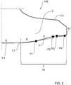
- FIG. 2 shows a schematic cross-sectional view of a portion of a valve 100 according to an embodiment of the invention in solid lines, the dotted line for comparison, in principle, the course of the edge region of the valve 1 from FIG. 1 shows.
- the valve 100 comprises a valve disk 3 with a front surface 3.1 and a rear surface 3.2.
- the front surface 3.1 of the valve disk 3 comprises an edge region 10 and a bulge A which is arranged substantially centrally outwards, the bulge A having a summit region 3.4.
- the edge region 10 is expediently limited in cross section by a laterally inner end E1 and a laterally outer end E2.
- the inner end E1 adjoins the summit region 3.4, whereby the outer end E2 can represent the outermost lateral end of the front surface 3.1 or of the valve disk 3.
- the edge region 10 extends annularly around the bulge A of the valve disk 3 and is partially laterally adjacent to and outside the bulge A and partially on the Bulge A arranged.
- the bulge A itself may be at least partially formed substantially spherical, parabolic or frusto-conical.
- a special feature of the valve 100 is that a laterally outer portion of the edge portion 10 is made flatter compared to a laterally inner portion of the edge portion 10 and the edge portion 10 in cross section a plurality of discontinuities P1 to P4 to the mass of the write-off A, in particular the Mass of bulge base, reduce.
- the front surface 3.1 can be expediently shaped essentially S-shaped in cross-section.
- the outer portion of the edge portion 10 is formed bulge-free, so that the outer portion has a slope of substantially 0 ° and thus the outer portion of the edge portion 10 has a lower pitch compared to the inner portion of the edge portion 10
- the outer portion may also have slopes in a range of preferably about +/- 5 °.
- the bulge A of the valve 100 does not extend to the laterally outer end E2, so that at least the outer portion of the edge region 10 deviates from the spherical, parabolic or frusto-conical bulge A.
- the plurality of discontinuities P1 to P4 in cross-section can be expediently formed by at least one vertex, inflection point or turning point or a combination thereof.
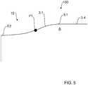
- FIGS. 3 to 5 show schematic cross-sectional views of a portion of a valve 100 according to other embodiments of the invention.
- FIG. 3 shows in particular an edge region 10 with sections running linearly in cross section and a discontinuity P1.
- FIG. 4 shows in particular an edge region 10 with curved portions extending in cross section and two discontinuities P1 and P2.
- FIG. 5 shows in particular an edge region 10 with curved portions extending in cross section and a discontinuity P1.
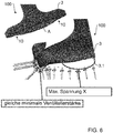
- FIG. 6 shows a perspective side view of a valve 100 according to an embodiment of the invention, wherein FIG. 7 a perspective side view of the buckle valve 1 shows.
- valve 100 is therefore made to reduce the reduction of Discharge A of the valve disk 3, the outer portion of the edge portion 10 flattened compared to the inner portion of the edge portion 10, wherein the edge portion 10 in cross section at least one discontinuity P1 to P4 comprises, thereby characterized in the Operation not or only insignificantly stressed mass to remove.
Landscapes
- Engineering & Computer Science (AREA)
- General Engineering & Computer Science (AREA)
- Mechanical Engineering (AREA)
- Physics & Mathematics (AREA)
- Geometry (AREA)
- Lift Valve (AREA)
- Exhaust Silencers (AREA)
- Check Valves (AREA)
Abstract
Description
- Die Erfindung betrifft ein Ventil, vorzugsweise ein Abgas- und/oder Gaswechselventil, für einen Verbrennungsmotor, zweckmäßig für ein Kraftfahrzeug, insbesondere ein Nutzfahrzeug, z. B. einen Lastkraftwagen oder einen Omnibus. Ebenso kann das Ventil für Offroad-, marine und/oder stationäre Verbrennungsmotoren dienen.
- Ventile für Verbrennungsmotoren von Kraftfahrzeugen mit einem Ventilschaft und einem Ventilteller sind in den unterschiedlichsten Ausführungsformen bekannt. So sind aus dem Stand der Technik Ventile mit flacher Vorderfläche und Hohlventile mit nach außen ausgebauchter Vorderfläche bekannt. Die ausgebauchte Vorderfläche dient dazu, Platz für Kühlkanäle-/ räume zu schaffen oder die mechanische Festigkeit des durch einen Hohlraum geschwächten Ventils zu erhöhen. Durch hohe Zünddrücke und insbesondere durch innermotorische Abgasmaßnahmen (z. B. Abgasnormen, z. B. Euro-Norm 5 oder besser) erzieltem, sehr sauberem Abgas neigen Ventilteller und Ventilsitze zu starkem, abrasivem Verschleiß. Grund dafür ist die elastische Verformung des Ventiltellers und das Gleiten des Ventiltellers auf dem Ventilsitz während den Zünddruckbelastungen. Problematisch ist, dass sehr sauberes Abgas gegenüber schmutzigem Abgas keinen oder nur noch sehr wenig Schmierstoff (Ruß) zur Verschleißminderung zwischen Ventil und Ventilsitz zur Verfügung stellt. Um den Verschleiß zwischen Ventil und Ventilsitz zu reduzieren, ist es aus der Praxis bekannt, relativ teure verschleißfeste Werkstoffe und/oder kleine, allerdings strömungsungünstige Ventilsitzwinkel (z. B. kleiner 30°) zu verwenden.
- Aus der
DE 10 2014 013 503 A1 ist bereits ein Wölb-Ventil bekannt, das trotz sauberem, insbesondere rußarmen Abgas bei Zünddruckbelastung nicht oder zumindest nur geringfügig auf dem Ventilsitzring gleitet und dadurch einen geringen Verschleiß aufweist, vorzugsweise ohne Strömungsnachteile in Kauf nehmen zu müssen. Nachteilig daran ist allerdings die relativ große Ausbauchung des Ventiltellers, die einerseits Zusatzgewicht mit sich bringt und andererseits im Betrieb relativ tief im Brennraum steht. Das inDE 10 2014 013 503 A1 offenbarte Wölb-Ventil ist folglich in seiner Masse normalerweise schwerer als Standardventile, was einen Einfluss auf die Dynamik des Ventiltriebs zur Folge hat. Darüber hinaus ragt im Betrieb die Ausbauchung üblicherweise weiter in den Brennraum als bei Standardventilen. Das hat zur Folge, dass große Ventiltaschen am Kolben benötigt werden, welche das System verteuern. Der Ventilüberstand beeinflusst außerdem die Verbrennung. Im Speziellen bei Ottomotoren kann durch eine ungünstige Anordnung die Zündung verschlechtert werden, da die turbulent kinetische Energie (TKE) und Ladungsbewegung reduziert werden. - Eine Aufgabe der Erfindung ist es, ein konstruktiv einfach bzw. kostengünstig herzustellendes Ventil für einen Verbrennungsmotor zu schaffen, das relativ leichtgewichtig ist und/oder dessen Einfluss auf die Verbrennung des Verbrennungsmotors reduziert ist, insbesondere im Vergleich zu dem in
DE 10 2014 013 503 A1 beschriebenen Wölb-Ventil. - Diese Aufgabe kann mit den Merkmalen des unabhängigen Anspruchs gelöst werden. Vorteilhafte Weiterbildungen der Erfindung können den Unteransprüchen und der folgenden Beschreibung bevorzugter Ausführungsformen der Erfindung entnommen werden.
- Die Erfindung schafft ein Ventil, vorzugsweise ein Abgas- und/oder Gaswechselventil, für einen Verbrennungsmotor, vorzugsweise für ein Kraftfahrzeug. Das Ventil weist z. B. einen Ventilschaft und einen Ventilteller auf. Der Ventilteller umfasst eine Vorderfläche und eine Rückfläche. Die Vorderfläche dient zweckmäßig zum lastseitigen, insbesondere Brennraum- und/oder Druckraum-seitigen, Platzieren, so dass sie zweckmäßig im Betrieb der Lastseite, insbesondere der Druck- und/oder Brennraum-Seite zugewandt ist.
- Vorzugsweise weist die Vorderfläche des Ventiltellers eine zweckmäßig im Wesentlichen mittig angeordnete Ausbauchung mit einem Gipfelbereich auf. Die Vorderfläche weist zweckmäßig ferner einen Randbereich auf, der sich insbesondere um die Ausbauchung herum erstrecken kann und vorzugsweise abschnittsweise Teil der Ausbauchung sein kann und abschnittsweise seitlich neben und außerhalb der Ausbauchung verlaufen kann.
- Das Ventil zeichnet sich insbesondere dadurch aus, dass, vorzugsweise zur Massereduzierung der Ausbauchung des Ventiltellers, insbesondere zur Massereduzierung der Ausbauchungsbasis (zweckmäßig Ausbauchungsboden), ein seitlich äußerer Teilabschnitt des Randbereichs flacher ausgeführt ist im Vergleich zu einem seitlich inneren Teilabschnitt des Randbereichs und/oder der Randbereich zweckmäßig im Querschnitt zumindest eine Diskontinuität umfasst.
- Darüber hinaus kann dadurch zweckmäßig eine Querschnittsfläche der Ausbauchung reduziert werden, so dass vorzugsweise im Betrieb die Störfläche reduziert werden kann.
- Das Ventil wie hierin offenbart kann vorzugsweise dem Prinzip nach im Wesentlichen gemäß dem in der
DE 10 2014 013 503 A1 beschriebenen Wölb-Ventil ausgeführt sein. Bei dem inDE 10 2014 013 503 A1 beschriebenen Wölb-Ventil ist es möglich, dass der Randbereich im Betrieb nicht oder zumindest nicht wesentlich beansprucht wird, z. B. durch eine Druck- und/oder Ventilfederkraft. - Das Ventil wie hierin offenbart ist deshalb vorzugsweise so ausgeführt, dass die im Betrieb nicht oder nur unwesentlich beanspruchte Masse im Randbereich der Ausbauchung, insbesondere die im Betrieb nicht oder nur unwesentlich beanspruchte Masse der Ausbauchungsbasis, zumindest im Wesentlichen entfernt wurde.
- Trotz im Vergleich zum Wölb-Ventil gemäß
DE 10 2014 013 503 A1 gleicher minimaler Wandstärke des Ventiltellers kann dadurch z. B. ermöglicht werden, dass im Betrieb die maximale Spannung des wie hierin offenbarten Ventiltellers und die maximale Spannung des Ventiltellers gemäßDE 10 2014 013 503 A1 im Wesentlichen gleich groß sind. - Es ist möglich, dass die zumindest eine Diskontinuität zumindest einen Scheitelpunkt (z. B. zumindest einen Hochpunkt und/oder Tiefpunkt), zumindest einen Knickpunkt und/oder zumindest einen Wendpunkt umfasst.
- Es ist möglich, dass im Querschnitt die zumindest eine Diskontinuität relativ zu einem seitlich inneren Ende des Randbereichs außenseitig angeordnet ist und/oder relativ zu einem seitlich äußeren Ende des Randbereichs innenseitig angeordnet ist.
- Das seitlich innere Ende kann z. B. an den Gipfelbereich anschließen, wobei alternativ oder ergänzend das seitlich äußere Ende das vorzugsweise seitlich äußerste Ende der Vorderfläche darstellen kann.
- Es ist möglich, dass der äußere Teilabschnitt des Randbereichs eine geringere Steigung aufweist im Vergleich zu dem inneren Teilabschnitt des Randbereichs.
- Der äußere Teilabschnitt des Randbereichs kann z. B. eine Steigung in einem Bereich von kleiner als ungefähr +/-5° aufweisen.
- Es ist möglich, dass der äußere Teilabschnitt des Randbereichs zumindest abschnittsweise im Wesentlichen Ausbauchungs-frei ausgeführt ist und/oder die Ausbauchung sich nicht bis zu einem seitlich äußeren Ende des Ventiltellers und/oder der Vorderfläche erstreckt.
- Die Ausbauchung des Ventiltellers kann z. B. zumindest abschnittsweise durch eine im Wesentlichen sphärische, parabolische oder kegelstumpfförmige Ausformung gebildet sein, wobei optional der äußere Teilabschnitt des Randbereichs von der im Wesentlichen sphärischen, parabolischen oder kegelstumpfförmigen Ausformung abweichen kann.
- Es ist möglich, dass die Ausbauchung und/oder der Gipfelbereich im Wesentlichen mittig angeordnet sind.
- Der äußere Teilabschnitt des Randbereichs kann vorzugsweise den seitlich äußersten Teil der Vorderfläche umfassen, wobei der innere Teilabschnitt des Randbereichs z. B. zwischen dem Gipfelbereich und dem äußeren Teilabschnitt des Randbereichs angeordnet sein kann.
- Es ist möglich, dass der innere Teilabschnitt des Randbereichs einen seitlichen Teil der Ausbauchung bildet und/oder sich der äußere Teilabschnitt des Randbereichs sich z. B. seitlich neben und vorzugsweise außerhalb der Ausbauchung erstreckt.
- Der äußere Teilabschnitt des Randbereichs und/oder die zumindest eine Diskontinuität kann sich z. B. im Wesentlichen ringförmig erstrecken, z. B. im Wesentlichen rotationssymmetrisch erstrecken.
- Bei einer Ausführungsform kann z. B. die Vorderfläche des Ventiltellers und/oder der Ventilteller vorzugsweise im Wesentlichen rotationssymmetrisch ausgeformt sein.
- Zu erwähnen ist, dass im Kontext der Erfindung die Vorderfläche des Ventiltellers und somit vorzugsweise die Ausbauchung, der Gipfelbereich und/oder der Randbereich z. B. zumindest abschnittsweise linear und/oder gekrümmt (z. B. bogenförmig) ausgeformt sein können.
- Zu erwähnen ist nochmals, dass die Ausbauchung vorzugsweise im Wesentlichen sphärisch, parabolisch oder kegelstumpfförmig ausgeformt sein kann.
- Es ist möglich, dass das Ventil als Vollventil und/oder Wölb-Ventil ausgeführt ist.
- Es ist möglich, dass sich die neutrale Faser des Ventiltellers zumindest abschnittsweise, zweckmäßig zum überwiegenden Teil, lastseitig, also im Betrieb auf der Lastseite, insbesondere auf einer Druck- und/oder Brennraum-Seite, einer fiktiven bzw. gedachten Bezugsebene erstreckt, die zweckmäßig durch die wirksame Mitte der Ventilsitzfläche des Ventiltellers und quer zum Ventilschaft verläuft. Die wirksame Mitte der Ventilsitzfläche des Ventiltellers wird zweckmäßig durch die Mitte der Kontaktfläche zwischen der Ventilsitzfläche des Ventiltellers und eines Ventilsitzes hierfür definiert.
- Die neutrale Faser des Ventiltellers kann sich insbesondere zum überwiegenden Teil lastseitig der Bezugsebene erstrecken, z. B. zu mehr als 50%, 60%, 70%, 80%, 90% oder sogar zu mehr als 95% und/oder quasi gänzlich im Ventiltellerbereich seitlich des Ventilschafts (also insbesondere unter Ausblendung des Ventilschafts).
- Bei einer Ausführungsform der Erfindung erstreckt sich die resultierende Wirklinie des Ventiltellers, also quasi dessen neutrale Faser, vorzugsweise zum überwiegenden Teil lastseitig der resultierenden Wirklinie der Ventilsitzfläche, also quasi der Bezugsebene.
- Als Vollventil im Rahmen der Erfindung sind vorzugsweise massive Ventile gemeint, insbesondere Ventile mit einem massiven Ventilschaft und/oder einem massiven Ventilteller, also insbesondere ohne Hohlraum, ohne Kühlhohlraum und/oder ohne Kühlleitungen.
- Die Ventilsitzfläche des Ventiltellers ist vorzugsweise schräg ausgeführt.
- Es ist möglich, dass der zweckmäßig kanalseitige Tulpenwinkel der Rückfläche des Ventiltellers kleiner ist als 20°, 15°, 12°, 10° oder 8°. Dabei kann die Rückfläche z. B. geradlinig oder gekrümmt ausgeformt sein.
- Eine gewisse Verschleißminderung kann auch durch Wahl eines kleinen Ventilsitzwinkels von im Extremfall 0° erzielt werden, wodurch jedoch der Strömungswiderstand des Ventils steigt, so dass der Gaswechsel behindert wird und der Kraftstoffverbrauch des Verbrennungsmotors steigt.
- Gemäß einer Ausführungsform der Erfindung ist der Ventilsitzwinkel der Ventilsitzfläche des Ventiltellers zweckmäßig größer als 25°, 30°, 35°, 40° oder 45° und/oder kleiner als 70°, 65°, 60°, 55° oder 50°, so dass eine Gleit- und somit Verschleißreduzierung ohne Strömungsnachteile ermöglicht wird.
- Die neutrale Faser, also insbesondere die Materialmitte, des Ventiltellers verläuft insbesondere so, dass sie zur Lastseite (insbesondere Brennraum- und/oder zur Druckraum-Seite) hin und/oder nach außen ausgebaucht ist.
- Der Gipfelbereich der neutralen Faser kann relativ zum Ventilschaft vorzugsweise außermittig und/oder koaxial verlaufen, insbesondere ringförmig.
- Es ist möglich, dass die Vorderfläche des Ventiltellers sphärisch, parabolisch oder kegelstumpfförmig ausgebaucht ist. Eine sphärische oder parabolische Ausbauchung ist zwar ideal oder zumindest vorteilhaft, allerdings aufwendig zu fertigen. Sie können deshalb durch eine zweckmäßig flache kegelstumpfförmige Ausbauchung angenähert werden.
- Der Gipfelbereich der Vorderfläche des Ventiltellers ist relativ zum Ventilschaft vorzugsweise mittig ausgerichtet ist.
- Der Verbrennungsmotor ist vorzugsweise ein Diesel-, oder Gas- bzw. Otto-Verbrennungsmotor.
- Die Rückfläche des Ventiltellers ist vorzugsweise flacher ausgeformt als die Vorderfläche des Ventiltellers. Dabei kann die Rückfläche und/oder die Vorderfläche z. B. geradlinig und/oder gekrümmt ausgeformt sein.
- Wie schon zuvor erwähnt, wird die wirksame Mitte der Ventilsitzfläche des Ventiltellers durch die Mitte der Kontaktfläche zwischen der Ventilsitzfläche des Ventiltellers und eines Ventilsitzes hierfür definiert. Im Rahmen der Erfindung kann die wirksame Mitte der Ventilsitzfläche des Ventiltellers somit relativ zu der Ventilsitzfläche des Ventiltellers z. B. tatsächlich mittig angeordnet sein, allerdings auch außermittig.
- Es ist möglich, dass die Vorderfläche des Ventiltellers im Querschnitt z. B. zumindest abschnittsweise im Wesentlichen S-förmig ausgebildet ist, vorzugsweise umfassend die Ausbauchung und/oder den seitlich äußeren Teilabschnitt des Randbereichs.
- Die im Wesentlichen S-Form kann sich z. B. ringförmig erstrecken, vorzugsweise rotationssymmetrisch erstrecken.
- Die Erfindung ist nicht auf ein Ventil beschränkt, sondern umfasst auch eine Ventil-Ventilsitz-Kombination mit einem Ventil wie hierin offenbart und einem Ventilsitz hierfür.
- Der Erfindung umfasst zudem ein Kraftfahrzeug, vorzugsweise ein Nutzfahrzeug, insbesondere einen Lastkraftwagen oder einen Omnibus, mit vorzugsweise einem Verbrennungsmotor, der einen Brenn- und/oder Druckraum mit einer Ventil-Ventilsitz-Kombination wie hierin beschrieben umfasst.
- Die zuvor beschriebenen bevorzugten Ausführungsformen und Merkmale der Erfindung sind miteinander kombinierbar. Andere vorteilhafte Weiterbildungen der Erfindung sind in den Unteransprüchen offenbart oder ergeben sich aus der folgenden Beschreibung bevorzugter Ausführungsformen der Erfindung in Verbindung mit den beigefügten Figuren.
- Figur 1
- zeigt eine schematische Querschnittsansicht eines Teils zweier Ventile gemäß Stand der Technik,
- Figur 2
- zeigt eine schematische Querschnittsansicht eines Teils eines Ventils gemäß einer Ausführungsform der Erfindung,
- Figur 3
- zeigt eine schematische Querschnittsansicht eines Teils eines Ventils gemäß einer anderen Ausführungsform der Erfindung,
- Figur 4
- zeigt eine schematische Querschnittsansicht eines Teils eines Ventils gemäß einer wiederum anderen Ausführungsform der Erfindung,
- Figur 5
- zeigt eine schematische Querschnittsansicht eines Teils eines Ventils gemäß einer noch anderen Ausführungsform der Erfindung,
- Figur 6
- zeigt eine perspektivische Seitenansicht eines Ventils gemäß einer Ausführungsform der Erfindung, und
- Figur 7
- zeigt eine perspektivische Seitenansicht eines Ventils gemäß Stand der Technik.
- Die in den Figuren gezeigten Ausführungsformen stimmen teilweise überein, so dass für ähnliche oder im Wesentlichen gleiche Teile die gleichen Bezugszeichen verwendet sind, wobei zu deren Erläuterung auch auf die Beschreibung der anderen Ausführungsformen verwiesen wird, um Wiederholungen zu vermeiden.
-
Figur 1 zeigt eine schematische Ansicht eines Teils eines Wölb-Ventils 1 gemäßDE 10 2014 013 503 A1 für einen Otto- oder Gasmotor bzw. einen die Abgasnorm Euro ≥ 5 erfüllenden Diesel-Motor, so dass das Ventil 1 mit relativ sauberen, rußarmen Abgas beaufschlagt wird.Figur 1 zeigt zum Vergleich hierzu ebenfalls schematisch ein Ventil V, das ebenfalls in derDE 10 2014 013 503 A1 beschrieben ist. - Das erfindungsgemäße Ventil 100 kann zunächst dem Prinzip nach im Wesentlichen wie das in
Figur 1 zu sehende Wölb-Ventil 1 ausgebildet sei. - Das Ventil 1 umfasst einen Ventilschaft 2 und einen Ventilteller 3. Der Ventilteller 3 umfasst eine Vorderfläche 3.1, die im Betrieb einem Druck-/Brennraum P (Lastseite) zugewandt ist, eine Rückfläche 3.2, die im Betrieb dem Druck-/Brennraum P abgewandt ist, und eine zweckmäßig schräge Ventilsitzfläche 3.3 zum Aufsitzen auf einem Ventilsitz (Sitzring) 5.
- Die Vorderfläche 3.1 ist nach außen, im Betrieb zur Lastseite P (Druck-/Brennraum) hin ausgebaucht und das Ventil 1 ist als massives Vollventil und somit hohlraumfrei, insbesondere kühlleitungsfrei und kühlhohlraumfrei ausgeführt.
- Die neutrale Faser 4 und somit die Mittellinie des Ventiltellers 3 ist ebenfalls zur Lastseite P hin ausgebaucht, insbesondere so, dass sie sich zweckmäßig zumindest zum überwiegenden Teil lastseitig, also im Betrieb auf der Lastseite P, einer fiktiven bzw. gedachten Bezugsebene BE erstreckt. Die Bezugsebene BE verläuft durch die wirksame Mitte M der Ventilsitzfläche 3.3 des Ventiltellers 3 und quer zum Ventilschaft 2. Die neutrale Faser 4 kennzeichnet quasi die resultierende Wirklinie des Ventiltellers 3, während die Bezugsebene BE quasi die resultierende Wirklinie der Ventilsitzfläche 3.3 kennzeichnet.
- Die wirksame Mitte M der Ventilsitzfläche 3.3 des Ventiltellers 3 wird somit durch die im Betrieb resultierende Mitte der Kontaktfläche zwischen der Ventilsitzfläche 3.3 des Ventiltellers 3 und des Ventilsitzes 5 definiert.
- Insbesondere dadurch, dass das Ventil 1 als Vollventil mit nach außen ausgebauchter Vorderfläche 3.1 ausgeführt ist, kann die neutrale Faser 4 des Ventiltellers 3 zumindest großteils lastseitig der Bezugsebene BE verlaufen, so dass bei Zünddruckbelastung kein oder nur ein sehr geringes Gleiten der Ventilsitzfläche 3.3 auf dem Ventilsitz 5 entsteht. Da Gleiten die Hauptursache des Verschleißes zwischen Ventil 1 und Ventilsitz 5 ist, wird folglich trotz kein oder kaum Schmiermittel in Form von Ruß lieferndem, relativ sauberem Abgas der Verschleiß vermindert oder beseitigt.
- Der Gipfelbereich 3.4 der Vorderfläche 3.1 des Ventiltellers 3 ist relativ zum Ventilschaft 2 im Wesentlichen mittig ausgerichtet.
- Der Gipfelbereich 4.1 der neutralen Faser 4 verläuft wegen dem Ventilschaft 2 relativ zum Ventilschaft 2 außermittig und ringförmig koaxial zum Ventilschaft 2.
- Die Rückfläche 3.2 des Ventiltellers 3 ist zweckmäßig flacher ausgeführt als die Vorderfläche 3.1 des Ventiltellers 3. Die Vorderfläche 3.1 und/oder die Rückfläche 3.2 können z. B. geradlinig oder gekrümmt ausgeführt sein.
- Der Tulpenwinkel α der Rückfläche 3.2 des Ventiltellers 3 ist kleiner als 20°, in der gezeigten Ausführungsform ca. 7°.
- Der Ventilsitzwinkel β der Ventilsitzfläche 3.3 ist größer als 25°, in der gezeigten Ausführungsform ca. 40°.
- In
Figur 1 ist darüber hinaus ein anderes Ventil V gemäß Stand der Technik mit einer neutralen Faser F angedeutet. - Der Vergleich zwischen dem Ventil 1 und dem Ventil V zeigt, dass der kanalseitige Tulpenwinkel α des Ventils 1 kleiner (flacher) ist als bei dem Ventil V, im Gegenzug die Vorderfläche 3.1 allerdings verstärkt und ausgebaucht ist, so dass die neutrale Faser 4 zum Druck-/Brennraum P hin ausgebaucht ist. Die Ausformung des Ventils 1 führt zu einer Verstärkung des Ventils 1, insbesondere des Ventiltellers 3 auf der Brenn-/Druckraum P zugewandten Seite und einem Abmagern auf der Brenn-/Druckraum P abgewandten Seite. Die neutrale Faser F des Ventils V gemäß Stand der Technik verläuft relativ zu der Bezugsebene BE auf der der Lastseite P abgewandten Seite, also in
Figur 1 oberhalb der Bezugsebene BE. -
Figur 2 zeigt eine schematische Querschnittsansicht eines Teils eines Ventils 100 gemäß einer Ausführungsform der Erfindung in durchgezogenen Linien, wobei die gepunktete Linie zum Vergleich prinzipiell den Verlauf des Randbereichs des Ventils 1 ausFigur 1 zeigt. - Das Ventil 100 umfasst einen Ventilteller 3 mit einer Vorderfläche 3.1 und einer Rückfläche 3.2. Die Vorderfläche 3.1 des Ventiltellers 3 umfasst einen Randbereich 10 und eine im Wesentlichen mittig angeordnete Ausbauchung A nach außen, wobei die Ausbauchung A einen Gipfelbereich 3.4 aufweist.
- Der Randbereich 10 wird zweckmäßig im Querschnitt durch ein seitlich inneres Ende E1 und ein seitlich äußeres Ende E2 begrenzt. Das innere Ende E1 schließt an den Gipfelbereich 3.4 an, wobei das äußere Ende E2 das äußerste seitliche Ende der Vorderfläche 3.1 bzw. des Ventiltellers 3 darstellen kann.
- Der Randbereich 10 erstreckt sich ringförmig um die Ausbauchung A des Ventiltellers 3 und ist dabei teilweise seitlich neben und außerhalb der Ausbauchung A und teilweise auf der Ausbauchung A angeordnet. Die Ausbauchung A selbst kann zumindest abschnittsweise im Wesentlichen sphärisch, parabolisch oder kegelstumpfförmig ausgeformt sein.
- Eine Besonderheit des Ventils 100 ist, dass ein seitlich äußerer Teilabschnitt des Randbereichs 10 flacher ausgeführt ist im Vergleich zu einem seitlich inneren Teilabschnitt des Randbereichs 10 und der Randbereich 10 im Querschnitt mehrere Diskontinuitäten P1 bis P4 umfasst, um die Masse der Ausbuchung A, insbesondere die Masse der Ausbauchungsbasis, zu reduzieren. Dadurch kann die Vorderfläche 3.1 im Querschnitt zweckmäßig im Wesentlichen S-förmig ausgeformt werden.
- Bei der in
Figur 2 gezeigten Ausführungsform ist der äußere Teilabschnitt des Randbereichs 10 Ausbauchungs-frei ausgeführt, so dass der äußere Teilabschnitt eine Steigung von im Wesentlichen 0° aufweist und folglich der äußere Teilabschnitt des Randbereichs 10 eine geringere Steigung aufweist im Vergleich zu dem inneren Teilabschnitt des Randbereichs 10. Im Kontext der Erfindung kann der äußere Teilabschnitt allerdings auch Steigungen in einem Bereich von vorzugsweise ungefähr +/- 5° aufweisen. - Im Gegensatz zum Wölb-Ventil 1 erstreckt sich die Ausbauchung A des Ventils 100 nicht bis zum seitlich äußeren Ende E2, so dass zumindest der äußere Teilabschnitt des Randbereichs 10 von der sphärischen, parabolischen oder kegelstumpfförmigen Ausbauchung A abweicht.
- Die im Querschnitt mehreren Diskontinuitäten P1 bis P4 können zweckmäßig durch zumindest einen Scheitelpunkt, Knickpunkt oder Wendpunkt oder eine Kombination hiervon gebildet werden.
- Die
Figuren 3 bis 5 zeigen schematische Querschnittsansichten eines Teils eines Ventils 100 gemäß anderer Ausführungsformen der Erfindung. -
Figur 3 zeigt dabei insbesondere einen Randbereich 10 mit im Querschnitt linear verlaufenden Teilabschnitten und einer Diskontinuität P1. -
Figur 4 zeigt dabei insbesondere einen Randbereich 10 mit im Querschnitt gekrümmt verlaufenden Teilabschnitten und zwei Diskontinuitäten P1 und P2. -
Figur 5 zeigt dabei insbesondere einen Randbereich 10 mit im Querschnitt gekrümmt verlaufenden Teilabschnitten und einer Diskontinuität P1. -
Figur 6 zeigt eine perspektivische Seitenansicht eines Ventils 100 gemäß einer Ausführungsform der Erfindung, wobeiFigur 7 eine perspektivische Seitenansicht des Wölb-Ventils 1 zeigt. - Bei dem in
Figur 7 zu sehenden Wölb-Ventil 1, das wie schon zuvor erwähnt gemäßDE 10 2014 013 503 A1 ausgeführt sein kann, ist es möglich, dass der Randbereich des Ventiltellers 3, insbesondere die Ausbauchungsbasis, im Betrieb, z. B. durch eine Druck- und/oder Ventilfederkraft, nicht oder zumindest nicht wesentlich beansprucht wird. - Bei dem in
Figur 6 zu sehenden Ventil 100 ist deshalb zur Massereduzierung der Ausbuchung A des Ventiltellers 3 der äußere Teilabschnitt des Randbereichs 10 flacher ausgeführt im Vergleich zu dem inneren Teilabschnitt des Randbereichs 10, wobei der Randbereich 10 im Querschnitt zumindest eine Diskontinuität P1 bis P4 umfasst, um dadurch die im Betrieb nicht oder nur unwesentlich beanspruchte Masse zu entfernen. - Trotz im Vergleich zum Wölb-Ventil 1 gleicher minimaler Wandstärke des Ventiltellers kann dadurch ermöglicht werden, dass die maximale Spannung des Ventiltellers 3 des Ventils 100 und die maximale Spannung des Ventiltellers 3 des Wölb-Ventils 1 im Wesentlichen gleich bleiben, z. B. mit einer maximalen Spannung X von z. B. ungefähr 136 bis 137 Mpa.
- Die Erfindung ist nicht auf die oben beschriebenen bevorzugten Ausführungsformen beschränkt. Vielmehr ist eine Vielzahl von Varianten und Abwandlungen möglich, die ebenfalls von dem Erfindungsgedanken Gebrauch machen und deshalb in den Schutzbereich fallen. Darüber hinaus beansprucht die Erfindung auch Schutz für den Gegenstand und die Merkmale der Unteransprüche unabhängig von den in Bezug genommenen Merkmalen und Ansprüchen.
-
- 1
- Ventil gemäß Stand der Technik
- 2
- Ventilschaft
- 3
- Ventilteller
- 3.1
- Vorderfläche des Ventiltellers
- 3.2
- Rückfläche des Ventiltellers
- 3.3
- Ventilsitzfläche
- 3.4
- Gipfelbereich der Vorderfläche des Ventiltellers
- 4
- Neutrale Faser
- 4.1
- Gipfelbereich der neutralen Faser
- 5
- Ventilsitz
- α
- Tulpenwinkel der Rückfläche des Ventiltellers
- β
- Ventilsitzwinkel der Ventilsitzfläche des Ventiltellers
- P
- Lastseite, insbesondere Brenn- und/oder Druckraum-Seite
- BE
- Bezugsebene
- M
- Wirksame Mitte der Ventilsitzfläche
- V
- Ventil gemäß Stand der Technik
- F
- Neutrale Faser des Ventiltellers des Ventils V
- 100
- Ventil
- 10
- Randbereich
- P1
- Diskontinuität
- P2
- Diskontinuität
- P3
- Diskontinuität
- P4
- Diskontinuität
- A
- Ausbauchung
- E1
- Seitlich inneres Ende
- E2
- Seitlich äußeres Ende
Claims (18)
- Ventil (100), vorzugsweise Abgas- und/oder Gaswechselventil (100), mit: einem eine Vorderfläche (3.1) und eine Rückfläche (3.2) aufweisenden Ventilteller (3), wobei die Vorderfläche (3.1) des Ventiltellers (3) eine einen Gipfelbereich (3.4) aufweisende Ausbauchung (A) und einen Randbereich (10) umfasst, dadurch gekennzeichnet, dass, vorzugsweise zur Massereduzierung der Ausbauchung (A) des Ventiltellers (3), ein seitlich äußerer Teilabschnitt des Randbereichs (10) flacher ausgeführt ist im Vergleich zu einem seitlich inneren Teilabschnitt des Randbereichs (10) und/oder der Randbereich (10) im Querschnitt zumindest eine Diskontinuität (P1-P4) umfasst.
- Ventil (100) nach Anspruch 1, dadurch gekennzeichnet, dass die zumindest eine Diskontinuität (P1-P4) zumindest einen Scheitelpunkt, Knickpunkt und/oder Wendpunkt umfasst.
- Ventil (100) nach Anspruch 1 oder 2, dadurch gekennzeichnet, dass im Querschnitt die zumindest eine Diskontinuität (P1-P4) relativ zu einem seitlich inneren Ende (E1) des Randbereichs (10) außenseitig angeordnet ist und/oder relativ zu einem seitlich äußeren Ende (E2) des Randbereichs (10) innenseitig angeordnet ist.
- Ventil (100) nach Anspruch 3, dadurch gekennzeichnet, dass das innere seitliche Ende (E1) an den Gipfelbereich (3.4) anschließt und/oder das äußere seitliche Ende (E2) das äußerste seitliche Ende der Vorderfläche (3.1) darstellt.
- Ventil (100) nach einem der vorhergehenden Ansprüche, dadurch gekennzeichnet, dass der äußere Teilabschnitt des Randbereichs (10) eine geringere Steigung aufweist im Vergleich zu dem inneren Teilabschnitt des Randbereichs (10) und/oder der äußere Teilabschnitt des Randbereichs (10) eine Steigung in einem Bereich von kleiner als +/-5° aufweist.
- Ventil (100) nach einem der vorhergehenden Ansprüche, dadurch gekennzeichnet, dass der äußere Teilabschnitt des Randbereichs (10) zumindest abschnittsweise im Wesentlichen Ausbauchungs-frei ausgeführt ist und/oder die Ausbauchung (A) sich nicht bis zu einem seitlich äußeren Ende (E2) des Ventiltellers (3) erstreckt.
- Ventil (100) nach einem der vorhergehenden Ansprüche, dadurch gekennzeichnet, dass die Ausbauchung (A) des Ventiltellers (3) durch eine sphärische, parabolische oder kegelstumpfförmige Ausformung gebildet wird, wobei vorzugsweise der äußere Teilabschnitt des Randbereichs (10) von der sphärischen, parabolischen oder kegelstumpfförmigen Ausformung abweicht.
- Ventil (100) nach einem der vorhergehenden Ansprüche, dadurch gekennzeichnet, dass die Ausbauchung des Ventiltellers (3) mittig angeordnet ist und der äußere Teilabschnitt des Randbereichs (10) den seitlich äußersten Teil der Vorderfläche (3.1) umfasst.
- Ventil (100) nach einem der vorhergehenden Ansprüche, dadurch gekennzeichnet, dass der innere Teilabschnitt des Randbereichs (10) einen seitlichen Teil der Ausbauchung (A) bildet und/oder der äußere Teilabschnitt des Randbereichs (10) sich seitlich neben und außerhalb der Ausbauchung (A) erstreckt.
- Ventil (100) nach einem der vorhergehenden Ansprüche, dadurch gekennzeichnet, dass der äußere Teilabschnitt des Randbereichs (10) und/oder die zumindest eine Diskontinuität (P1-P4) sich ringförmig erstreckt, vorzugsweise rotationssymmetrisch erstreckt.
- Ventil (100) nach einem der vorhergehenden Ansprüche, dadurch gekennzeichnet, dass das Ventil (100) als Vollventil ausgeführt ist und/oder sich eine neutrale Faser (4) des Ventiltellers (3) abschnittsweise lastseitig einer gedachten Bezugsebene (BE) erstreckt, wobei die Bezugsebene (BE) durch die wirksame Mitte (M) einer Ventilsitzfläche (3.3) des Ventiltellers (3) und quer zu einem Ventilschaft (2) des Ventils (100) verläuft.
- Ventil (100) nach Anspruch 11, dadurch gekennzeichnet, dass die neutrale Faser (4) des Ventiltellers (3) zur Lastseite (P) hin ausgebaucht ist.
- Ventil (100) nach Anspruch 11 oder 12, dadurch gekennzeichnet, dass der Gipfelbereich (4.1) der neutralen Faser (4) relativ zum Ventilschaft (2) außermittig verläuft.
- Ventil (100) nach einem der Ansprüche 11 bis 13, dadurch gekennzeichnet, dass sich die neutrale Faser (4) des Ventiltellers (3) zum überwiegenden Teil lastseitig der Bezugsebene (BE) erstreckt.
- Ventil (100) nach einem der Ansprüche 11 bis 14, dadurch gekennzeichnet, dass die wirksame Mitte (M) der Ventilsitzfläche (3.3) des Ventiltellers (3) durch die Mitte der Kontaktfläche zwischen der Ventilsitzfläche (3.3) des Ventiltellers (3) und eines Ventilsitzes (5) definiert wird.
- Ventil (100) nach einem der vorhergehenden Ansprüche, dadurch gekennzeichnet, dass die Vorderfläche (3.1) des Ventiltellers (3) im Querschnitt zumindest abschnittsweise S-förmig ausgebildet ist.
- Ventil-Ventilsitz-Kombination mit einem Ventil (100) nach einem der vorhergehenden Ansprüche und einem Ventilsitz (5) für das Ventil (100).
- Kraftfahrzeug, vorzugsweise Nutzfahrzeug, mit einer Ventil-Ventilsitz-Kombination nach Anspruch 17.
Applications Claiming Priority (1)
| Application Number | Priority Date | Filing Date | Title |
|---|---|---|---|
| DE102017119887.3A DE102017119887A1 (de) | 2017-08-30 | 2017-08-30 | Ventil für einen Verbrennungsmotor |
Publications (3)
| Publication Number | Publication Date |
|---|---|
| EP3450707A1 true EP3450707A1 (de) | 2019-03-06 |
| EP3450707B1 EP3450707B1 (de) | 2020-09-30 |
| EP3450707B2 EP3450707B2 (de) | 2023-08-16 |
Family
ID=63108459
Family Applications (1)
| Application Number | Title | Priority Date | Filing Date |
|---|---|---|---|
| EP18186481.0A Active EP3450707B2 (de) | 2017-08-30 | 2018-07-31 | Ventil für einen verbrennungsmotor |
Country Status (6)
| Country | Link |
|---|---|
| US (1) | US10934900B2 (de) |
| EP (1) | EP3450707B2 (de) |
| JP (1) | JP2019044766A (de) |
| CN (1) | CN109578104B (de) |
| BR (1) | BR102018017351B1 (de) |
| DE (1) | DE102017119887A1 (de) |
Families Citing this family (3)
| Publication number | Priority date | Publication date | Assignee | Title |
|---|---|---|---|---|
| DE102017119887A1 (de) | 2017-08-30 | 2019-02-28 | Man Truck & Bus Ag | Ventil für einen Verbrennungsmotor |
| US11215092B2 (en) | 2019-12-17 | 2022-01-04 | Caterpillar Inc. | Engine valve with raised ring or dimple |
| DE102023115185A1 (de) | 2023-06-12 | 2023-08-31 | Daimler Truck AG | Einblasesystem für einen Gasmotor |
Citations (5)
| Publication number | Priority date | Publication date | Assignee | Title |
|---|---|---|---|---|
| EP0369967A1 (de) * | 1988-11-15 | 1990-05-23 | Ab Volvo | Ventilvorrichtung in einer Brennkraftmaschine |
| EP1193375A1 (de) * | 2000-09-29 | 2002-04-03 | Ford Global Technologies, Inc., A subsidiary of Ford Motor Company | Ventil für Brennkraftmaschinen |
| WO2005085605A1 (de) * | 2004-03-03 | 2005-09-15 | Mahle Ventiltrieb Gmbh | Gaswechselventil eines verbrennungsmotors |
| JP2008240535A (ja) * | 2007-03-26 | 2008-10-09 | Sgg Kenkyusho:Kk | ポペット弁による既燃ガスの制御装置 |
| DE102014013503A1 (de) * | 2014-09-11 | 2016-03-17 | Man Truck & Bus Ag | Ventil für einen Verbrennungsmotor |
Family Cites Families (29)
| Publication number | Priority date | Publication date | Assignee | Title |
|---|---|---|---|---|
| US1338759A (en) | 1919-05-14 | 1920-05-04 | Self Seating Valve Company | Valve |
| US1467414A (en) | 1922-03-03 | 1923-09-11 | Hugo J Bachman | Poppet valve |
| DE452903C (de) | 1924-10-22 | 1927-11-22 | Aaron Montgomery Searles | Tellerventil |
| GB255222A (en) | 1925-07-06 | 1926-07-22 | Albert Otto Hinsch | Improvements in valves for internal combustion engines |
| DE518822C (de) | 1928-10-06 | 1931-02-20 | Marc Birkigt | Ventil fuer Brennkraftmaschinen |
| US1916550A (en) * | 1931-05-14 | 1933-07-04 | Stanwood Corp | Internal combustion engine |
| US2089749A (en) | 1933-11-02 | 1937-08-10 | Eaton Mfg Co | Valve |
| US2152428A (en) | 1937-09-27 | 1939-03-28 | Raymond T Scull | Valve |
| US2401006A (en) * | 1942-03-18 | 1946-05-28 | Longoria Antonio | Process of bonding metal |
| US2386003A (en) | 1943-10-28 | 1945-10-02 | Wesley R Peck | Compensating poppet valve |
| US2435948A (en) * | 1944-09-08 | 1948-02-10 | Thompson Prod Inc | Method of preparing composite poppet valves |
| US3086506A (en) | 1960-07-19 | 1963-04-23 | Dobrosavljevic Sloboda Milivoy | Air-cooled two-stroke diesel engine |
| FR1302524A (fr) * | 1961-07-17 | 1962-08-31 | Citroen Sa Andre | Perfectionnements aux moteurs à combustion interne |
| DK144217C (da) | 1979-08-29 | 1982-06-21 | B & W Diesel As | Udstoedsventil til en forbraendingsmotor |
| JPS5937221A (ja) | 1982-08-26 | 1984-02-29 | Nippon Zosen Kikai Kk | ポペット弁およびその製造法 |
| US4815706A (en) | 1988-01-15 | 1989-03-28 | Feuling James J | Values for improved fluid flow therearound |
| US6679219B1 (en) | 2000-02-23 | 2004-01-20 | Louis A. Pacinelli | Intake and exhaust valves for internal combustion engines |
| JP2001280515A (ja) | 2000-03-29 | 2001-10-10 | Nissan Diesel Motor Co Ltd | Egrバルブ |
| JP4771868B2 (ja) | 2006-06-06 | 2011-09-14 | サンコール株式会社 | 内燃機関用バルブ構造 |
| DE102006061128B4 (de) * | 2006-12-22 | 2015-06-11 | Mahle International Gmbh | Gaswechselventil eines Verbrennungsmotors |
| JP5148609B2 (ja) | 2008-10-10 | 2013-02-20 | 日鍛バルブ株式会社 | 中空ポペットバルブおよびその製造方法 |
| DE102009000509B4 (de) | 2009-01-09 | 2026-02-05 | Robert Bosch Gmbh | Einspritzventil und Dosiersystem für eine Abgasnachbehandlungseinrichtung |
| JP5036799B2 (ja) | 2009-12-21 | 2012-09-26 | 川崎重工業株式会社 | 4ストローク内燃機関 |
| US8960148B2 (en) | 2012-07-11 | 2015-02-24 | George McGinnis | Heat transferring engine valve for fuel conservation |
| PL2915892T3 (pl) | 2012-10-31 | 2018-07-31 | Fukuda Metal Foil & Powder Co., Ltd. | Stop na bazie Ni-Cr-Co mający właściwości odporności na korozję wysokotemperaturową oraz zawór grzybkowy mający powierzchnię nim modyfikowaną |
| DE102013210900A1 (de) | 2013-06-11 | 2014-12-11 | Mahle International Gmbh | Gaswechselventil einer Brennkraftmaschine |
| DE102013216188A1 (de) * | 2013-08-14 | 2015-03-12 | Mahle International Gmbh | Leichtmetalleinlassventil |
| US20170152768A1 (en) | 2015-12-01 | 2017-06-01 | Caterpillar Inc. | Engine valve |
| DE102017119887A1 (de) | 2017-08-30 | 2019-02-28 | Man Truck & Bus Ag | Ventil für einen Verbrennungsmotor |
-
2017
- 2017-08-30 DE DE102017119887.3A patent/DE102017119887A1/de not_active Withdrawn
-
2018
- 2018-07-31 EP EP18186481.0A patent/EP3450707B2/de active Active
- 2018-08-23 BR BR102018017351-0A patent/BR102018017351B1/pt active IP Right Grant
- 2018-08-28 CN CN201810989380.4A patent/CN109578104B/zh active Active
- 2018-08-29 US US16/116,466 patent/US10934900B2/en active Active
- 2018-08-30 JP JP2018160954A patent/JP2019044766A/ja active Pending
Patent Citations (5)
| Publication number | Priority date | Publication date | Assignee | Title |
|---|---|---|---|---|
| EP0369967A1 (de) * | 1988-11-15 | 1990-05-23 | Ab Volvo | Ventilvorrichtung in einer Brennkraftmaschine |
| EP1193375A1 (de) * | 2000-09-29 | 2002-04-03 | Ford Global Technologies, Inc., A subsidiary of Ford Motor Company | Ventil für Brennkraftmaschinen |
| WO2005085605A1 (de) * | 2004-03-03 | 2005-09-15 | Mahle Ventiltrieb Gmbh | Gaswechselventil eines verbrennungsmotors |
| JP2008240535A (ja) * | 2007-03-26 | 2008-10-09 | Sgg Kenkyusho:Kk | ポペット弁による既燃ガスの制御装置 |
| DE102014013503A1 (de) * | 2014-09-11 | 2016-03-17 | Man Truck & Bus Ag | Ventil für einen Verbrennungsmotor |
Also Published As
| Publication number | Publication date |
|---|---|
| CN109578104B (zh) | 2022-04-19 |
| DE102017119887A1 (de) | 2019-02-28 |
| CN109578104A (zh) | 2019-04-05 |
| US20190063271A1 (en) | 2019-02-28 |
| BR102018017351A2 (pt) | 2019-04-16 |
| EP3450707B1 (de) | 2020-09-30 |
| BR102018017351A8 (pt) | 2023-03-07 |
| RU2018130501A3 (de) | 2022-03-24 |
| RU2018130501A (ru) | 2020-02-25 |
| US10934900B2 (en) | 2021-03-02 |
| BR102018017351B1 (pt) | 2023-03-28 |
| EP3450707B2 (de) | 2023-08-16 |
| JP2019044766A (ja) | 2019-03-22 |
Similar Documents
| Publication | Publication Date | Title |
|---|---|---|
| EP2480783B1 (de) | Kraftstoff-einspritzventil für eine brennkraftmaschine | |
| DE112019005122T5 (de) | Ventilsitzring für motor mit doppelballiger sitzoberfläche, profiliert zum begrenzen des ventilrückgangs | |
| DE3604661C2 (de) | ||
| EP3450707B1 (de) | Ventil für einen verbrennungsmotor | |
| EP2162613B1 (de) | Kolben einer brennkfraftmaschine mit einer erhöhten schrägstellung der kastenwände des kolbens | |
| EP1092104B1 (de) | Kolbenbolzenbuchse | |
| EP1412625B1 (de) | Zylinderkopf für eine brennkraftmaschine | |
| EP3000997A1 (de) | Ventil für einen verbrennungsmotor | |
| WO2016023543A1 (de) | Verriegelungsvorrichtung für eine schaltbare ventiltriebkomponente | |
| EP3371443B1 (de) | Optimierte nabenabstützung | |
| WO2015154853A1 (de) | Kolben für eine brennkraftmaschine | |
| EP3688293B1 (de) | Verbrennungsmotor | |
| DE102004024056B4 (de) | Ventil für eine Abgasleitung | |
| DE102013226606A1 (de) | Fluidverteiler mit einem Druckspeicher | |
| DE102018210565A1 (de) | Hubkolbenbrennkraftmaschine mit mehreren Zylindern und mindestens einer Abschaltvorrichtung | |
| DE10118910B4 (de) | Kolbenringanordnung | |
| DE102019119854A1 (de) | Pleuel für eine Brennkraftmaschine mit variabler Verdichtung | |
| DE102020004367A1 (de) | Kolben mit Reibleistungsreduzierung für eine Brennkraftmaschine | |
| EP3545182B1 (de) | Stahlkolben für einen verbrennungsmotor | |
| DE102015203936A1 (de) | Pleuel, Hubkolbenmaschine, Kraftfahrzeug | |
| DE102013225903A1 (de) | Bauteil mit einem Ventilsitz sowie Ventilsitzring | |
| DE102007053371A1 (de) | Zylinderkopf für eine Brennkraftmaschine | |
| DE102015202166A1 (de) | Brennraumstruktur eines Verbrennungsmotors | |
| DE102006051256A1 (de) | Ventiltriebs-Hebel für eine Brennkraftmaschine | |
| DE19754138A1 (de) | Hubventil einer Brennkraftmaschine, insbesondere Einlaß-Hubventil |
Legal Events
| Date | Code | Title | Description |
|---|---|---|---|
| PUAI | Public reference made under article 153(3) epc to a published international application that has entered the european phase |
Free format text: ORIGINAL CODE: 0009012 |
|
| STAA | Information on the status of an ep patent application or granted ep patent |
Free format text: STATUS: THE APPLICATION HAS BEEN PUBLISHED |
|
| AK | Designated contracting states |
Kind code of ref document: A1 Designated state(s): AL AT BE BG CH CY CZ DE DK EE ES FI FR GB GR HR HU IE IS IT LI LT LU LV MC MK MT NL NO PL PT RO RS SE SI SK SM TR |
|
| AX | Request for extension of the european patent |
Extension state: BA ME |
|
| RAP1 | Party data changed (applicant data changed or rights of an application transferred) |
Owner name: MAN TRUCK & BUS SE |
|
| STAA | Information on the status of an ep patent application or granted ep patent |
Free format text: STATUS: REQUEST FOR EXAMINATION WAS MADE |
|
| 17P | Request for examination filed |
Effective date: 20190903 |
|
| RBV | Designated contracting states (corrected) |
Designated state(s): AL AT BE BG CH CY CZ DE DK EE ES FI FR GB GR HR HU IE IS IT LI LT LU LV MC MK MT NL NO PL PT RO RS SE SI SK SM TR |
|
| GRAP | Despatch of communication of intention to grant a patent |
Free format text: ORIGINAL CODE: EPIDOSNIGR1 |
|
| STAA | Information on the status of an ep patent application or granted ep patent |
Free format text: STATUS: GRANT OF PATENT IS INTENDED |
|
| INTG | Intention to grant announced |
Effective date: 20200512 |
|
| GRAS | Grant fee paid |
Free format text: ORIGINAL CODE: EPIDOSNIGR3 |
|
| GRAA | (expected) grant |
Free format text: ORIGINAL CODE: 0009210 |
|
| STAA | Information on the status of an ep patent application or granted ep patent |
Free format text: STATUS: THE PATENT HAS BEEN GRANTED |
|
| AK | Designated contracting states |
Kind code of ref document: B1 Designated state(s): AL AT BE BG CH CY CZ DE DK EE ES FI FR GB GR HR HU IE IS IT LI LT LU LV MC MK MT NL NO PL PT RO RS SE SI SK SM TR |
|
| REG | Reference to a national code |
Ref country code: CH Ref legal event code: EP Ref country code: GB Ref legal event code: FG4D Free format text: NOT ENGLISH |
|
| REG | Reference to a national code |
Ref country code: AT Ref legal event code: REF Ref document number: 1319004 Country of ref document: AT Kind code of ref document: T Effective date: 20201015 |
|
| REG | Reference to a national code |
Ref country code: DE Ref legal event code: R096 Ref document number: 502018002593 Country of ref document: DE |
|
| REG | Reference to a national code |
Ref country code: IE Ref legal event code: FG4D Free format text: LANGUAGE OF EP DOCUMENT: GERMAN |
|
| REG | Reference to a national code |
Ref country code: SE Ref legal event code: TRGR |
|
| REG | Reference to a national code |
Ref country code: NL Ref legal event code: FP |
|
| PG25 | Lapsed in a contracting state [announced via postgrant information from national office to epo] |
Ref country code: HR Free format text: LAPSE BECAUSE OF FAILURE TO SUBMIT A TRANSLATION OF THE DESCRIPTION OR TO PAY THE FEE WITHIN THE PRESCRIBED TIME-LIMIT Effective date: 20200930 Ref country code: GR Free format text: LAPSE BECAUSE OF FAILURE TO SUBMIT A TRANSLATION OF THE DESCRIPTION OR TO PAY THE FEE WITHIN THE PRESCRIBED TIME-LIMIT Effective date: 20201231 Ref country code: NO Free format text: LAPSE BECAUSE OF FAILURE TO SUBMIT A TRANSLATION OF THE DESCRIPTION OR TO PAY THE FEE WITHIN THE PRESCRIBED TIME-LIMIT Effective date: 20201230 Ref country code: FI Free format text: LAPSE BECAUSE OF FAILURE TO SUBMIT A TRANSLATION OF THE DESCRIPTION OR TO PAY THE FEE WITHIN THE PRESCRIBED TIME-LIMIT Effective date: 20200930 Ref country code: BG Free format text: LAPSE BECAUSE OF FAILURE TO SUBMIT A TRANSLATION OF THE DESCRIPTION OR TO PAY THE FEE WITHIN THE PRESCRIBED TIME-LIMIT Effective date: 20201230 |
|
| PG25 | Lapsed in a contracting state [announced via postgrant information from national office to epo] |
Ref country code: LV Free format text: LAPSE BECAUSE OF FAILURE TO SUBMIT A TRANSLATION OF THE DESCRIPTION OR TO PAY THE FEE WITHIN THE PRESCRIBED TIME-LIMIT Effective date: 20200930 Ref country code: RS Free format text: LAPSE BECAUSE OF FAILURE TO SUBMIT A TRANSLATION OF THE DESCRIPTION OR TO PAY THE FEE WITHIN THE PRESCRIBED TIME-LIMIT Effective date: 20200930 |
|
| REG | Reference to a national code |
Ref country code: LT Ref legal event code: MG4D |
|
| PG25 | Lapsed in a contracting state [announced via postgrant information from national office to epo] |
Ref country code: LT Free format text: LAPSE BECAUSE OF FAILURE TO SUBMIT A TRANSLATION OF THE DESCRIPTION OR TO PAY THE FEE WITHIN THE PRESCRIBED TIME-LIMIT Effective date: 20200930 Ref country code: SM Free format text: LAPSE BECAUSE OF FAILURE TO SUBMIT A TRANSLATION OF THE DESCRIPTION OR TO PAY THE FEE WITHIN THE PRESCRIBED TIME-LIMIT Effective date: 20200930 Ref country code: CZ Free format text: LAPSE BECAUSE OF FAILURE TO SUBMIT A TRANSLATION OF THE DESCRIPTION OR TO PAY THE FEE WITHIN THE PRESCRIBED TIME-LIMIT Effective date: 20200930 Ref country code: PT Free format text: LAPSE BECAUSE OF FAILURE TO SUBMIT A TRANSLATION OF THE DESCRIPTION OR TO PAY THE FEE WITHIN THE PRESCRIBED TIME-LIMIT Effective date: 20210201 Ref country code: RO Free format text: LAPSE BECAUSE OF FAILURE TO SUBMIT A TRANSLATION OF THE DESCRIPTION OR TO PAY THE FEE WITHIN THE PRESCRIBED TIME-LIMIT Effective date: 20200930 Ref country code: EE Free format text: LAPSE BECAUSE OF FAILURE TO SUBMIT A TRANSLATION OF THE DESCRIPTION OR TO PAY THE FEE WITHIN THE PRESCRIBED TIME-LIMIT Effective date: 20200930 |
|
| PG25 | Lapsed in a contracting state [announced via postgrant information from national office to epo] |
Ref country code: PL Free format text: LAPSE BECAUSE OF FAILURE TO SUBMIT A TRANSLATION OF THE DESCRIPTION OR TO PAY THE FEE WITHIN THE PRESCRIBED TIME-LIMIT Effective date: 20200930 Ref country code: IS Free format text: LAPSE BECAUSE OF FAILURE TO SUBMIT A TRANSLATION OF THE DESCRIPTION OR TO PAY THE FEE WITHIN THE PRESCRIBED TIME-LIMIT Effective date: 20210130 Ref country code: AL Free format text: LAPSE BECAUSE OF FAILURE TO SUBMIT A TRANSLATION OF THE DESCRIPTION OR TO PAY THE FEE WITHIN THE PRESCRIBED TIME-LIMIT Effective date: 20200930 Ref country code: ES Free format text: LAPSE BECAUSE OF FAILURE TO SUBMIT A TRANSLATION OF THE DESCRIPTION OR TO PAY THE FEE WITHIN THE PRESCRIBED TIME-LIMIT Effective date: 20200930 |
|
| REG | Reference to a national code |
Ref country code: DE Ref legal event code: R026 Ref document number: 502018002593 Country of ref document: DE |
|
| PG25 | Lapsed in a contracting state [announced via postgrant information from national office to epo] |
Ref country code: SK Free format text: LAPSE BECAUSE OF FAILURE TO SUBMIT A TRANSLATION OF THE DESCRIPTION OR TO PAY THE FEE WITHIN THE PRESCRIBED TIME-LIMIT Effective date: 20200930 |
|
| PLBI | Opposition filed |
Free format text: ORIGINAL CODE: 0009260 |
|
| PLAX | Notice of opposition and request to file observation + time limit sent |
Free format text: ORIGINAL CODE: EPIDOSNOBS2 |
|
| 26 | Opposition filed |
Opponent name: MAHLE INTERNATIONAL GMBH Effective date: 20210629 |
|
| PG25 | Lapsed in a contracting state [announced via postgrant information from national office to epo] |
Ref country code: DK Free format text: LAPSE BECAUSE OF FAILURE TO SUBMIT A TRANSLATION OF THE DESCRIPTION OR TO PAY THE FEE WITHIN THE PRESCRIBED TIME-LIMIT Effective date: 20200930 |
|
| PLBB | Reply of patent proprietor to notice(s) of opposition received |
Free format text: ORIGINAL CODE: EPIDOSNOBS3 |
|
| PG25 | Lapsed in a contracting state [announced via postgrant information from national office to epo] |
Ref country code: SI Free format text: LAPSE BECAUSE OF FAILURE TO SUBMIT A TRANSLATION OF THE DESCRIPTION OR TO PAY THE FEE WITHIN THE PRESCRIBED TIME-LIMIT Effective date: 20200930 |
|
| REG | Reference to a national code |
Ref country code: CH Ref legal event code: PL |
|
| PG25 | Lapsed in a contracting state [announced via postgrant information from national office to epo] |
Ref country code: MC Free format text: LAPSE BECAUSE OF FAILURE TO SUBMIT A TRANSLATION OF THE DESCRIPTION OR TO PAY THE FEE WITHIN THE PRESCRIBED TIME-LIMIT Effective date: 20200930 |
|
| REG | Reference to a national code |
Ref country code: BE Ref legal event code: MM Effective date: 20210731 |
|
| PG25 | Lapsed in a contracting state [announced via postgrant information from national office to epo] |
Ref country code: LI Free format text: LAPSE BECAUSE OF NON-PAYMENT OF DUE FEES Effective date: 20210731 Ref country code: CH Free format text: LAPSE BECAUSE OF NON-PAYMENT OF DUE FEES Effective date: 20210731 |
|
| PG25 | Lapsed in a contracting state [announced via postgrant information from national office to epo] |
Ref country code: IS Free format text: LAPSE BECAUSE OF FAILURE TO SUBMIT A TRANSLATION OF THE DESCRIPTION OR TO PAY THE FEE WITHIN THE PRESCRIBED TIME-LIMIT Effective date: 20210130 Ref country code: LU Free format text: LAPSE BECAUSE OF NON-PAYMENT OF DUE FEES Effective date: 20210731 |
|
| PG25 | Lapsed in a contracting state [announced via postgrant information from national office to epo] |
Ref country code: IE Free format text: LAPSE BECAUSE OF NON-PAYMENT OF DUE FEES Effective date: 20210731 Ref country code: BE Free format text: LAPSE BECAUSE OF NON-PAYMENT OF DUE FEES Effective date: 20210731 |
|
| PG25 | Lapsed in a contracting state [announced via postgrant information from national office to epo] |
Ref country code: CY Free format text: LAPSE BECAUSE OF FAILURE TO SUBMIT A TRANSLATION OF THE DESCRIPTION OR TO PAY THE FEE WITHIN THE PRESCRIBED TIME-LIMIT Effective date: 20200930 |
|
| PUAH | Patent maintained in amended form |
Free format text: ORIGINAL CODE: 0009272 |
|
| STAA | Information on the status of an ep patent application or granted ep patent |
Free format text: STATUS: PATENT MAINTAINED AS AMENDED |
|
| PG25 | Lapsed in a contracting state [announced via postgrant information from national office to epo] |
Ref country code: HU Free format text: LAPSE BECAUSE OF FAILURE TO SUBMIT A TRANSLATION OF THE DESCRIPTION OR TO PAY THE FEE WITHIN THE PRESCRIBED TIME-LIMIT; INVALID AB INITIO Effective date: 20180731 |
|
| 27A | Patent maintained in amended form |
Effective date: 20230816 |
|
| AK | Designated contracting states |
Kind code of ref document: B2 Designated state(s): AL AT BE BG CH CY CZ DE DK EE ES FI FR GB GR HR HU IE IS IT LI LT LU LV MC MK MT NL NO PL PT RO RS SE SI SK SM TR |
|
| REG | Reference to a national code |
Ref country code: DE Ref legal event code: R102 Ref document number: 502018002593 Country of ref document: DE |
|
| REG | Reference to a national code |
Ref country code: SE Ref legal event code: RPEO |
|
| REG | Reference to a national code |
Ref country code: NL Ref legal event code: FP |
|
| PG25 | Lapsed in a contracting state [announced via postgrant information from national office to epo] |
Ref country code: MK Free format text: LAPSE BECAUSE OF FAILURE TO SUBMIT A TRANSLATION OF THE DESCRIPTION OR TO PAY THE FEE WITHIN THE PRESCRIBED TIME-LIMIT Effective date: 20200930 |
|
| REG | Reference to a national code |
Ref country code: AT Ref legal event code: MM01 Ref document number: 1319004 Country of ref document: AT Kind code of ref document: T Effective date: 20230731 |
|
| PG25 | Lapsed in a contracting state [announced via postgrant information from national office to epo] |
Ref country code: MT Free format text: LAPSE BECAUSE OF FAILURE TO SUBMIT A TRANSLATION OF THE DESCRIPTION OR TO PAY THE FEE WITHIN THE PRESCRIBED TIME-LIMIT Effective date: 20200930 |
|
| PG25 | Lapsed in a contracting state [announced via postgrant information from national office to epo] |
Ref country code: AT Free format text: LAPSE BECAUSE OF NON-PAYMENT OF DUE FEES Effective date: 20230731 |
|
| PG25 | Lapsed in a contracting state [announced via postgrant information from national office to epo] |
Ref country code: AT Free format text: LAPSE BECAUSE OF NON-PAYMENT OF DUE FEES Effective date: 20230731 |
|
| PGFP | Annual fee paid to national office [announced via postgrant information from national office to epo] |
Ref country code: NL Payment date: 20250724 Year of fee payment: 8 |
|
| PGFP | Annual fee paid to national office [announced via postgrant information from national office to epo] |
Ref country code: DE Payment date: 20250728 Year of fee payment: 8 |
|
| PGFP | Annual fee paid to national office [announced via postgrant information from national office to epo] |
Ref country code: IT Payment date: 20250721 Year of fee payment: 8 |
|
| PGFP | Annual fee paid to national office [announced via postgrant information from national office to epo] |
Ref country code: GB Payment date: 20250722 Year of fee payment: 8 |
|
| PGFP | Annual fee paid to national office [announced via postgrant information from national office to epo] |
Ref country code: FR Payment date: 20250725 Year of fee payment: 8 |
|
| PGFP | Annual fee paid to national office [announced via postgrant information from national office to epo] |
Ref country code: SE Payment date: 20250725 Year of fee payment: 8 |
|
| PG25 | Lapsed in a contracting state [announced via postgrant information from national office to epo] |
Ref country code: TR Free format text: LAPSE BECAUSE OF FAILURE TO SUBMIT A TRANSLATION OF THE DESCRIPTION OR TO PAY THE FEE WITHIN THE PRESCRIBED TIME-LIMIT Effective date: 20200930 |
|
| PGFP | Annual fee paid to national office [announced via postgrant information from national office to epo] |
Ref country code: AT Payment date: 20260410 Year of fee payment: 5 |