EP3449783A1 - Récipient de cuisson comportant un fond muni d'éléments ferromagnétiques indépendants - Google Patents
Récipient de cuisson comportant un fond muni d'éléments ferromagnétiques indépendants Download PDFInfo
- Publication number
- EP3449783A1 EP3449783A1 EP18187150.0A EP18187150A EP3449783A1 EP 3449783 A1 EP3449783 A1 EP 3449783A1 EP 18187150 A EP18187150 A EP 18187150A EP 3449783 A1 EP3449783 A1 EP 3449783A1
- Authority
- EP
- European Patent Office
- Prior art keywords
- cooking vessel
- ferromagnetic elements
- thickness
- ferromagnetic
- balls
- Prior art date
- Legal status (The legal status is an assumption and is not a legal conclusion. Google has not performed a legal analysis and makes no representation as to the accuracy of the status listed.)
- Granted
Links
Images

Classifications
-
- A—HUMAN NECESSITIES
- A47—FURNITURE; DOMESTIC ARTICLES OR APPLIANCES; COFFEE MILLS; SPICE MILLS; SUCTION CLEANERS IN GENERAL
- A47J—KITCHEN EQUIPMENT; COFFEE MILLS; SPICE MILLS; APPARATUS FOR MAKING BEVERAGES
- A47J36/00—Parts, details or accessories of cooking-vessels
- A47J36/02—Selection of specific materials, e.g. heavy bottoms with copper inlay or with insulating inlay
-
- A—HUMAN NECESSITIES
- A47—FURNITURE; DOMESTIC ARTICLES OR APPLIANCES; COFFEE MILLS; SPICE MILLS; SUCTION CLEANERS IN GENERAL
- A47J—KITCHEN EQUIPMENT; COFFEE MILLS; SPICE MILLS; APPARATUS FOR MAKING BEVERAGES
- A47J27/00—Cooking-vessels
- A47J27/002—Construction of cooking-vessels; Methods or processes of manufacturing specially adapted for cooking-vessels
Definitions
- the present invention relates to a cooking vessel intended to be placed on an induction heating means for cooking food including a pan, a saucepan, a frying pan, a Dutch oven or a pressure cooker.
- Document is known FR2919484 a cooking vessel made from a sheet of metal or light-drawn alloy, comprising a bottom comprising a ferromagnetic plate made of a metal or alloy having different mechanical, thermal, physical properties and in particular a higher elastic limit than that of the metal or alloy of the sheet.
- the plate is embedded in the bottom by a striking operation.
- the ferromagnetic plate ensures the compatibility of the cooking vessel with an induction heater.
- the ferromagnetic plate has slots for dividing the ferromagnetic plate into elements that remain attached to each other. The division of the ferromagnetic plate into several elements makes it possible to limit the deformation of the bottom during heating related to the bimetallic effect of the bottom construction.
- the plate has attachment zones between the various elements and the surface of some elements remains important. Thus, there will remain a deformation during heating.
- the surface of the ferromagnetic plate intended to be opposite the induction heating apparatus decreases, via the slots and other openings that are made there.
- the heating power transmitted to the cooking vessel during use is less and its ability to be heated by induction is less good.
- the object of the present invention is to overcome the aforementioned drawbacks and to provide a cooking vessel for cooperating with an induction heater which has an optimized operation.
- Another object of the invention is to provide a cooking vessel which is of simple design and economical to implement.
- a cooking vessel comprising a cap comprising a bottom intended to cooperate with induction heating means, said bottom having a thickness E and having ferromagnetic elements, characterized in that the ferromagnetic elements are independent of one another. others and are each inscribed in a sphere of diameter less than or equal to the thickness E.
- the ferromagnetic elements are distinct and are maintained on the cooking vessel, for example, by the bottom material.
- the ferromagnetic elements which each fit into a sphere of diameter less than the thickness E, can be completely embedded in the bottom, at least by more than half a diameter.
- Each ferromagnetic element is held in the bottom by the major part of its external surface to obtain an optimized mechanical connection.
- the compatibility of the cooking vessel with an induction heater is provided by a set of ferromagnetic elements of small size relative to the size of the bottom. Accordingly, during heating, the bottom can expand without being upset by the ferromagnetic elements and the bottom remains flat to ensure good coupling with the induction heater.
- the ferromagnetic elements are intended to cooperate with the induction heating apparatus to heat the bottom.
- the ferromagnetic elements comprise at least one plane face.
- the flat face is arranged parallel to the outer face of the bottom to ensure good coupling with the induction heater.
- the ferromagnetic elements comprise at least two parallel plane faces.
- the ferromagnetic elements can be made from a strip.
- the ferromagnetic elements are disks.
- Such a shape allows a good compromise between an expansion of the bottom minimized and a good coupling surface when the discs are arranged flat, side by side on the bottom.
- the discs have a diameter between the thickness E and three quarters of the thickness E.
- the discs have a thickness of between 0.4 and 0.8 millimeters, preferably 0.6 millimeters.
- Such thickness allows good coupling with the induction heater, while optimizing the amount of ferromagnetic material used.
- the ferromagnetic elements are balls.
- Such an arrangement allows the bottom to remain flat during heating.
- a ball has a large external surface that allows during heating to transfer the heat energy transmitted by the induction heater to the bottom.
- the balls have a diameter less than half the thickness E.
- This arrangement allows, especially when the balls are reported on the bottom by cold stamping, to embed the balls completely in the bottom with a creep of the bottom material and efforts compatible with industrial means.
- the ferromagnetic elements are reported on an outer face of the bottom.
- the ferromagnetic elements are closer to the induction heater when the container rests on the latter, to allow a good coupling.
- the bottom is made of a malleable metal material of the aluminum type and the ferromagnetic elements are attached to the outer face of the bottom by cold stamping.
- Such a process is particularly economical to achieve the assembly of the ferromagnetic elements on the outer face of the bottom.
- the ferromagnetic elements are partially embedded in the bottom.
- the bottom comprises a peripheral collar delimiting an implantation zone of the ferromagnetic elements.
- Such a flange can maintain the ferromagnetic elements during the striking operation.
- the distribution of the ferromagnetic elements is not homogeneous on the bottom.
- the bottom may have areas with particular heating characteristics when the cooking vessel cooperates with the induction heater, including areas with different temperatures or a different heating speed.
- the cooking vessel has a side wall, the bottom and the side wall having ferromagnetic elements.
- the cooking vessel is a pan, a saucepan, a sauté pan, a Dutch oven or a pressure cooker.
- a cooking vessel 1 constituted by a pan, comprises a cap 2 which comprises a bottom 3 and a side wall 4.
- the cap 2 is made of a non-magnetic material, in particular aluminum for example, by a striking operation of a disk or by a foundry operation.
- the cooking vessel 1 comprises a handle 7 for gripping to allow its manipulation.
- the bottom 3 of the cooking vessel 1 comprises an outer face 5 which has ferromagnetic elements 10.
- the ferromagnetic elements 10 allow the cooking vessel 1 to cooperate with an induction heater to heat it.
- the ferromagnetic elements take the form of balls 10.
- the balls 10 are made for example of ferritic stainless steel. In this embodiment, the balls 10 are distributed on a circular surface 6a centered on the outer face 5.
- the bottom 3 has a thickness E ( Fig.3 ) for example equal to four millimeters.
- a thickness E it is understood that the thickness is measured before the insertion of the balls 10.
- the cap 2 is made by striking from a disk thickness of four millimeters, the thickness E will correspond to the thickness of the disk, which is four millimeters.
- the balls 10 are embedded in the bottom by cold stamping.
- the balls 10 have a diameter D less than the thickness E, preferably less than half the thickness E. In the embodiment illustrated by the Figures 2 and 3 , the balls 10 have a diameter D of two millimeters.
- the balls 10 can be completely embedded in the bottom 3 so that the outer face 5 is flat. However, it is possible to embed the balls 10 over the majority of their respective diameters in order to leave an apparent part 11 ( Fig.3 ). In the embodiment illustrated by the Figures 2 and 3 , the balls 10 are embedded on three quarters of their diameter D.
- the balls 10 may be pre-positioned next to the aluminum disc with a magnetic stencil, thus keeping them in place during the striking operation.
- the bottom 3 of the cooking vessel comprises an outer face 5 which comprises ferromagnetic elements 20.
- the ferromagnetic elements take the form of discs 20.
- the discs 20 are made for example by cutting a strip into ferritic stainless steel.
- the discs (20) comprise two parallel plane faces (21, 22).
- the disks 20 are distributed on a circular surface 6b centered on the outer face 5.
- the bottom 3 has a thickness E ( Fig.5 ) for example equal to four millimeters.
- the disks 20 are embedded in the bottom 3 by cold stamping.
- the discs 20 have a diameter D equal to the thickness E.
- the discs 20 have a thickness e of 0.6 mm and are completely embedded in the bottom 3.
- the outer face 5 is flat and only the face 21 of each disc (20) is apparent ( Fig. 5 ).
- the ferromagnetic elements have a cylindrical shape.
- the ferromagnetic elements are obtained for example by cutting a wire.
Landscapes
- Engineering & Computer Science (AREA)
- Food Science & Technology (AREA)
- Manufacturing & Machinery (AREA)
- Cookers (AREA)
- Frying-Pans Or Fryers (AREA)
Abstract
Description
- La présente invention concerne un récipient de cuisson destiné à être disposé sur un moyen de chauffage par induction pour la cuisson d'aliments notamment une poêle, une casserole, une sauteuse, un faitout ou un autocuiseur.
- On connaît du document
FR2919484 - Cependant, la plaque comporte des zones d'attache entre les différents éléments et la surface de certains éléments reste importante. Ainsi, il subsistera une déformation lors de la chauffe.
- De plus, la surface de la plaque ferromagnétique destinée à être en regard de l'appareil de chauffage par induction diminue, via les fentes et autres ouvertures qui y sont pratiquées. Ainsi, la puissance de chauffe transmise au récipient de cuisson lors de son utilisation est moindre et sa capacité à être chauffé par induction est moins bonne.
- Le but de la présente invention est de remédier aux inconvénients précités et de proposer un récipient de cuisson destiné à coopérer avec un appareil de chauffage par induction qui présente un fonctionnement optimisé.
- Un autre but de l'invention est de proposer un récipient de cuisson qui soit de conception simple et économique à mettre en oeuvre.
- Ces buts sont atteints avec un récipient de cuisson comportant une calotte comprenant un fond destiné à coopérer avec un moyen de chauffage par induction, ledit fond présentant une épaisseur E et comportant des éléments ferromagnétiques, caractérisé en ce que les éléments ferromagnétiques sont indépendants les uns des autres et s'inscrivent chacun dans une sphère de diamètre inférieur ou égal à l'épaisseur E.
- Par indépendants les uns des autres, on comprend que les éléments ferromagnétiques sont distincts et sont maintenus sur le récipient de cuisson, par exemple, par la matière du fond.
- Les éléments ferromagnétiques qui s'inscrivent chacun dans une sphère de diamètre inférieur à l'épaisseur E, peuvent être encastrés totalement dans le fond, à minima par plus d'un demi diamètre.
- Chaque élément ferromagnétique est maintenu dans le fond par la majeure partie de sa surface externe pour obtenir une liaison mécanique optimisée.
- Ainsi, la compatibilité du récipient de cuisson avec un appareil de chauffage par induction est assurée par un ensemble d'éléments ferromagnétiques de petite taille par rapport à la taille du fond. En conséquence, lors de la chauffe, le fond peut se dilater sans être contrarié par les éléments ferromagnétiques et le fond reste plan pour garantir un bon couplage avec l'appareil de chauffage par induction.
- De manière avantageuse, seuls les éléments ferromagnétiques sont destinés à coopérer avec l'appareil de chauffage par induction pour faire chauffer le fond.
- De préférence, les éléments ferromagnétiques comportent au moins une face plane.
- Dans le cas où les éléments ferromagnétiques sont rapportés sur une face externe du fond, la face plane est agencée de manière parallèle à la face externe du fond pour garantir un bon couplage avec l'appareil de chauffage par induction.
- Avantageusement, les éléments ferromagnétiques comportent au moins deux faces planes parallèles.
- Ainsi, les éléments ferromagnétiques peuvent être fabriqués à partir d'un feuillard.
- De préférence, les éléments ferromagnétiques sont des disques.
- Une telle forme permet un bon compromis entre une dilatation du fond minimisée et une bonne surface de couplage lorsque les disques sont agencés à plat, côte à côte sur le fond.
- Avantageusement, les disques présentent un diamètre compris entre l'épaisseur E et les trois quarts de l'épaisseur E.
- La demanderesse a mis en évidence que dans cette plage de diamètre, on a de bons résultats en termes de déformation et de compatibilité induction par rapport aux appareils de chauffage par induction du commerce.
- De préférence, les disques présentent une épaisseur comprise entre 0,4 et 0,8 millimètre, de préférence 0,6 millimètre.
- De telles épaisseur permettent un bon couplage avec l'appareil de chauffage par induction, tout en optimisant la quantité de matière ferromagnétique mise en oeuvre.
- Avantageusement, les éléments ferromagnétiques sont des billes.
- Une telle disposition permet au fond de rester plan lors de la chauffe. De plus, une bille présente une surface externe importante qui permet lors de la chauffe de bien transférer l'énergie calorifique transmise par l'appareil de chauffe à induction vers le fond.
- De manière avantageuse, les billes présentent un diamètre inférieur à la moitié de l'épaisseur E.
- Cette disposition permet, notamment lorsque les billes sont rapportées sur le fond par frappe à froid, d'encastrer les billes complétement dans le fond avec un fluage de la matière de fond et des efforts compatibles avec des moyens industriels.
- De préférence, les éléments ferromagnétiques sont rapportés sur une face externe du fond.
- Ainsi, les éléments ferromagnétiques sont au plus près de l'appareil de chauffe à induction lorsque le récipient repose sur ce dernier, pour permettre un bon couplage.
- Avantageusement, le fond est réalisé en un matériau métallique malléable du type aluminium et les éléments ferromagnétiques sont rapportés sur la face externe du fond par frappe à froid.
- Un tel processus est particulièrement économique pour réaliser l'assemblage des éléments ferromagnétiques sur la face externe du fond.
- De plus, un tel processus permet à la matière du fond d'entourer les éléments ferromagnétiques pour obtenir une liaison mécanique optimisée.
- Un tel processus est particulièrement bien adapté si les éléments ferromagnétiques sont des billes qui ne nécessitent pas d'orientation avant la frappe.
- De préférence, les éléments ferromagnétiques sont encastrés partiellement dans le fond.
- Avantageusement, le fond comporte une collerette périphérique délimitant une zone d'implantation des éléments ferromagnétiques.
- Une telle collerette peut maintenir les éléments ferromagnétiques lors de l'opération de frappe.
- De préférence, la répartition des éléments ferromagnétiques n'est pas homogène sur le fond.
- Ainsi, le fond peut présenter des zones avec des caractéristiques de chauffe particulières lorsque le récipient de cuisson coopère avec l'appareil de chauffage à induction, notamment des zones présentant des températures différentes ou une rapidité de chauffe différente.
- De manière avantageuse, le récipient de cuisson comporte une paroi latérale, le fond et la paroi latérale comportant des éléments ferromagnétiques.
- Une telle disposition permet d'optimiser la surface de couplage avec l'appareil de chauffe à induction.
- Avantageusement, le récipient de cuisson est une poêle, une casserole, une sauteuse, un faitout ou un autocuiseur.
- L'invention sera mieux comprise à l'étude des modes de réalisation pris à titre nullement limitatif et illustrés dans les figures annexées dans lesquelles :
- La
figure 1 illustre une vue en perspective d'un récipient de cuisson munie des éléments ferromagnétiques selon un mode particulier de réalisation de l'invention. - La
figure 2 illustre une vue en perspective du dessous d'un secteur de la calotte du récipient de cuisson de lafigure 1 suivant les lignes II-II, le fond comportant des éléments ferromagnétiques formés par des billes. - La
figure 3 illustre une vue de détail en coupe de la calotte de lafigure 2 suivant la ligne III-III. - La
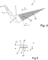
figure 4 illustre une vue en perspective du dessous d'un secteur de la calotte du récipient de cuisson de lafigure 1 , le fond comportant des éléments ferromagnétiques formés par des disques. - La
figure 5 illustre une vue de détail en coupe de la calotte de lafigure 4 suivant la ligne V-V. - Tel que visible à la
figure 1 , un récipient de cuisson 1, constitué par une poêle, comporte une calotte 2 qui comprend un fond 3 et une paroi latérale 4. La calotte 2 est réalisée en un matériau amagnétique, notamment en aluminium par exemple, par une opération de frappe d'un disque ou par une opération de fonderie. Le récipient de cuisson 1 comporte une poignée 7 de préhension pour permettre sa manipulation. - Conformément aux
figures 2 et 3 , le fond 3 du récipient de cuisson 1 comprend une face externe 5 qui comporte des éléments ferromagnétiques 10. Les éléments ferromagnétiques 10 permettent au récipient de cuisson 1 de coopérer avec un appareil de chauffage par induction pour le faire chauffer. Les éléments ferromagnétiques prennent la forme de billes 10. Les billes 10 sont réalisées par exemple en acier inoxydable ferritique. Dans ce mode de réalisation, les billes 10 sont réparties sur une surface circulaire 6a centrée sur la face externe 5. - Le fond 3 présente une épaisseur E (
Fig.3 ) par exemple égale à quatre millimètres. Par le fond présente une épaisseur E, on comprend que l'épaisseur est mesurée avant l'insertion des billes 10. Par exemple, si la calotte 2 est réalisée par frappe à partir d'un disque d'épaisseur quatre millimètres, l'épaisseur E correspondra à l'épaisseur du disque, soit quatre millimètres. Les billes 10 sont encastrées dans le fond par frappe à froid. Les billes 10 présentent un diamètre D inférieur à l'épaisseur E, de préférence inférieur à la moitié de l'épaisseur E. Dans le mode de réalisation illustré par lesfigures 2 et 3 , les billes 10 ont un diamètre D de deux millimètres. - Les billes 10 peuvent être encastrées complétement dans le fond 3 pour que la face externe 5 soit plane. On peut cependant encastrer les billes 10 sur la majorité de leur diamètre respectif pour laisser une partie 11 apparente (
Fig.3 ). Dans le mode de réalisation illustré par lesfigures 2 et 3 , les billes 10 sont encastrées sur les trois quarts de leur diamètre D. - Les billes 10 pourront être pré-positionnées en regard du disque en aluminium à l'aide d'un pochoir magnétique, permettant ainsi de les maintenir en place lors de l'opération de frappe.
- Conformément aux
figures 4 et 5 , le fond 3 du récipient de cuisson comprend une face externe 5 qui comporte des éléments ferromagnétiques 20. Dans ce mode de réalisation, les éléments ferromagnétiques prennent la forme de disques 20. Les disques 20 sont réalisés par exemple par découpe d'un feuillard en acier inoxydable ferritique. Les disques (20) comportent deux faces planes (21, 22) parallèles. Les disques 20 sont répartis sur une surface circulaire 6b centrée sur la face externe 5. - Le fond 3 présente une épaisseur E (
Fig.5 ) par exemple égale à quatre millimètres. Les disques 20 sont encastrés dans le fond 3 par frappe à froid. Les disques 20 présentent un diamètre D égal à l'épaisseur E. Les disques 20 présentent une épaisseur e de 0,6 millimètre et sont encastrés complétement dans le fond 3. Ainsi, la face externe 5 est plane et uniquement la face 21 de chaque disque (20) est apparente (Fig. 5 ). - Bien entendu, l'invention n'est nullement limitée aux modes de réalisation décrits et illustrés qui n'ont été donnés qu'à titre d'exemples. Des modifications restent possibles, notamment du point de vue de la constitution des divers éléments ou par substitution d'équivalents techniques, sans sortir pour autant du domaine de protection de l'invention.
- Ainsi, dans une variante de réalisation, les éléments ferromagnétiques présentent une forme cylindrique. Les éléments ferromagnétiques sont obtenus par exemple par découpe d'un fil.
Claims (14)
- Récipient de cuisson (1) comportant une calotte (2) comprenant un fond (3) destiné à coopérer avec un moyen de chauffage par induction, ledit fond (3) présentant une épaisseur E et comportant des éléments ferromagnétiques (10, 20), caractérisé en ce que les éléments ferromagnétiques (10, 20) sont indépendants les uns des autres et s'inscrivent chacun dans une sphère de diamètre inférieur ou égal à l'épaisseur E, les éléments ferromagnétiques (10, 20) assurant la compatibilité du récipient de cuisson (1) avec un appareil de chauffage par induction.
- Récipient de cuisson (1) selon la revendication 1, caractérisé en ce que les éléments ferromagnétiques (20) comportent au moins une face plane (21).
- Récipient de cuisson (1) selon l'une quelconque des revendications 1 à 2, caractérisé en ce que les éléments ferromagnétiques (20) comportent au moins deux faces planes (21, 22) parallèles.
- Récipient de cuisson (1) selon la revendication 3, caractérisé en ce que les éléments ferromagnétiques sont des disques (20).
- Récipient de cuisson (1) selon la revendication 4, caractérisé en ce que les disques (20) présentent un diamètre compris entre l'épaisseur E et les trois quarts de l'épaisseur E.
- Récipient de cuisson (1) selon l'une quelconque des revendications 4 ou 5, caractérisé en ce que les disques (20) présentent une épaisseur comprise entre 0,4 et 0, 8 millimètre, de préférence 0,6 millimètre.
- Récipient de cuisson (1) selon la revendication 1, caractérisé en ce que les éléments ferromagnétiques sont des billes (10).
- Récipient de cuisson (1) selon la revendication 7, caractérisé en ce que les billes (10) présentent un diamètre inférieur à la moitié de l'épaisseur E
- Récipient de cuisson (1) selon l'une quelconque des revendications 1 à 8, caractérisé en ce que les éléments ferromagnétiques (10, 20) sont rapportés sur une face externe (5) du fond (3)
- Récipient de cuisson (1) selon la revendication 9, caractérisé en ce que le fond (3) est réalisé en un matériau métallique malléable du type aluminium et en ce que les éléments ferromagnétiques (10, 20) sont rapportés sur la face externe (5) du fond (3) par frappe à froid.
- Récipient de cuisson (1) selon l'une quelconque des revendications 9 ou 10, caractérisé en ce que les éléments ferromagnétiques (10, 20) sont encastrés partiellement dans le fond (3).
- Récipient de cuisson (1) selon l'une quelconque des revendications 1 à 11, caractérisé en ce que le fond (3) comporte une collerette périphérique délimitant une zone d'implantation des éléments ferromagnétiques (10, 20).
- Récipient de cuisson (1) selon l'une quelconque des revendications 1 à 12, caractérisé en ce que la répartition des éléments ferromagnétiques (10, 20) n'est pas homogène sur le fond (3).
- Récipient de cuisson (1) selon l'une des revendications 1 à 13, caractérisé en ce qu'il est une poêle, une casserole, une sauteuse, un faitout ou un autocuiseur.
Applications Claiming Priority (1)
| Application Number | Priority Date | Filing Date | Title |
|---|---|---|---|
| FR1758015A FR3070246B1 (fr) | 2017-08-30 | 2017-08-30 | Recipient de cuisson comportant un fond muni d'elements ferromagnetiques independants |
Publications (2)
| Publication Number | Publication Date |
|---|---|
| EP3449783A1 true EP3449783A1 (fr) | 2019-03-06 |
| EP3449783B1 EP3449783B1 (fr) | 2022-08-31 |
Family
ID=60302271
Family Applications (1)
| Application Number | Title | Priority Date | Filing Date |
|---|---|---|---|
| EP18187150.0A Active EP3449783B1 (fr) | 2017-08-30 | 2018-08-02 | Récipient de cuisson comportant un fond muni d'éléments ferromagnétiques indépendants |
Country Status (4)
| Country | Link |
|---|---|
| EP (1) | EP3449783B1 (fr) |
| JP (1) | JP2019042495A (fr) |
| CN (1) | CN109419367A (fr) |
| FR (1) | FR3070246B1 (fr) |
Citations (4)
| Publication number | Priority date | Publication date | Assignee | Title |
|---|---|---|---|---|
| FR2689748A1 (fr) * | 1992-04-10 | 1993-10-15 | Seb Sa | Procédé pour limiter la température d'un corps chauffé au moyen d'un foyer à induction; corps et notamment récipients culinaires s'y rapportant. |
| US5694674A (en) * | 1991-03-27 | 1997-12-09 | Seb S.A. | Method for making a cooking vessel |
| FR2882240A1 (fr) * | 2005-10-05 | 2006-08-25 | Seb Sa | Article emaille comprenant un revetement compatible avec un mode de chauffage par induction et son procede de fabrication |
| US20080035139A1 (en) * | 2006-08-08 | 2008-02-14 | Attrezzeria Di Marin Visino & C. S.N.C. | Additional bottom adapted to be fixed to the outer surface of the bottom of a vessel |
Family Cites Families (15)
| Publication number | Priority date | Publication date | Assignee | Title |
|---|---|---|---|---|
| JPS5913239U (ja) * | 1982-07-19 | 1984-01-26 | 株式会社日本アルミ | アルミニウム及びアルミニウム合金製鍋類 |
| FR2674463B1 (fr) * | 1991-03-27 | 1995-07-07 | Seb Sa | Procede pour modifier les caracteristiques de la surface d'un metal, articles et recipients notamment culinaires obtenus. |
| DE10336325A1 (de) * | 2003-08-07 | 2005-03-10 | Albert Thomann | Induktions-Wok |
| JP3125303U (ja) * | 2006-07-03 | 2006-09-14 | 株式会社愛邦 | ボール |
| FR2917958B1 (fr) * | 2007-06-29 | 2009-09-11 | Seb Sa | Article culinaire emaille anti-rayures et procede de fabrication d'un tel article. |
| JP2009034378A (ja) * | 2007-08-02 | 2009-02-19 | Sumitomo Electric Fine Polymer Inc | 調理用加熱容器および調理用加熱容器の製造方法 |
| KR100834027B1 (ko) * | 2008-01-08 | 2008-05-30 | 김양영 | 인덕션 용기 |
| JP5082950B2 (ja) * | 2008-03-13 | 2012-11-28 | 住友化学株式会社 | 揮発性芳香族化合物の分解方法 |
| CN101327100A (zh) * | 2008-06-24 | 2008-12-24 | 施新委 | 铝锅复合锅底及其制造方法 |
| WO2011004919A1 (fr) * | 2009-07-07 | 2011-01-13 | (주)펠리테크 | Récipient de préparation d'aliment |
| CN102920312B (zh) * | 2012-11-02 | 2015-04-29 | 九阳股份有限公司 | 一种电磁感应加热烹调器用内锅及其加工方法 |
| FR3019022B1 (fr) * | 2014-03-26 | 2017-02-24 | Seb Sa | Appareil de cuisson d'aliments sous pression a baionnettes inversees et methode de fabrication afferente |
| FR3028403B1 (fr) * | 2014-11-13 | 2017-09-01 | Seb Sa | Systeme de cuisson sous pression equipe d'un dispositif de collecte de donnees |
| CN104797028A (zh) * | 2015-04-23 | 2015-07-22 | 合肥顺昌电磁感应科技有限公司 | 电磁感应式煎灶线圈 |
| WO2017113922A1 (fr) * | 2015-12-31 | 2017-07-06 | 佛山市顺德区美的电热电器制造有限公司 | Pot interne approprié pour chauffage électromagnétique et ustensile de cuisson le comprenant |
-
2017
- 2017-08-30 FR FR1758015A patent/FR3070246B1/fr not_active Expired - Fee Related
-
2018
- 2018-07-19 JP JP2018136168A patent/JP2019042495A/ja active Pending
- 2018-08-02 EP EP18187150.0A patent/EP3449783B1/fr active Active
- 2018-08-16 CN CN201810933491.3A patent/CN109419367A/zh active Pending
Patent Citations (4)
| Publication number | Priority date | Publication date | Assignee | Title |
|---|---|---|---|---|
| US5694674A (en) * | 1991-03-27 | 1997-12-09 | Seb S.A. | Method for making a cooking vessel |
| FR2689748A1 (fr) * | 1992-04-10 | 1993-10-15 | Seb Sa | Procédé pour limiter la température d'un corps chauffé au moyen d'un foyer à induction; corps et notamment récipients culinaires s'y rapportant. |
| FR2882240A1 (fr) * | 2005-10-05 | 2006-08-25 | Seb Sa | Article emaille comprenant un revetement compatible avec un mode de chauffage par induction et son procede de fabrication |
| US20080035139A1 (en) * | 2006-08-08 | 2008-02-14 | Attrezzeria Di Marin Visino & C. S.N.C. | Additional bottom adapted to be fixed to the outer surface of the bottom of a vessel |
Also Published As
| Publication number | Publication date |
|---|---|
| EP3449783B1 (fr) | 2022-08-31 |
| JP2019042495A (ja) | 2019-03-22 |
| FR3070246A1 (fr) | 2019-03-01 |
| FR3070246B1 (fr) | 2020-10-02 |
| CN109419367A (zh) | 2019-03-05 |
Similar Documents
| Publication | Publication Date | Title |
|---|---|---|
| EP0648459B1 (fr) | Récipient de cuisson à déformation de fond maitrisée | |
| EP2986191B1 (fr) | Recipient de cuisson comportant un capteur de temperature muni d'un element de fixation | |
| EP3593681B1 (fr) | Recipient de cuisson compatible induction comportant une plaque de fond ameliorée | |
| FR3006160A1 (fr) | Procede de realisation d'un canal de reception d'un capteur dans un recipient de cuisson | |
| EP3449783B1 (fr) | Récipient de cuisson comportant un fond muni d'éléments ferromagnétiques indépendants | |
| WO2008145927A1 (fr) | Article culinaire a portee amelioree et procede de fabrication | |
| EP4072386B1 (fr) | Dispositif de cuisson comportant un fond diffuseur multicouches | |
| KR20100117410A (ko) | 유도가열 주방용기에 사용되는 Cu함유 스텐레스강제 유도전열판 | |
| EP0970647B1 (fr) | Récipient de cuisson dont le fond est renforcé par une plaque et des gorges radiales | |
| EP2928350B1 (fr) | Article culinaire muni d'un fond comportant un matériau à bas point de curie | |
| EP2807966B1 (fr) | Récipient de cuisson comportant une plaque de fond munie de moyens d'accroche améliorés | |
| EP2693919B1 (fr) | Article culinaire a double paroi | |
| FR2711050A1 (fr) | Récipient à cuisson à fond indéformable. | |
| ES2678214T3 (es) | Placa de cocción a fuego lento para cocinas comerciales y residenciales | |
| FR2647003A1 (fr) | Recipient de cuisson, notamment poele ou casserole | |
| EP1400194B1 (fr) | Sous-ensemble chauffant d'un appareil electrique du type gaufrier | |
| FR3037492A1 (fr) | Ustensile de cuisson | |
| FR3096248B1 (fr) | Article culinaire comportant une paroi laterale amincie | |
| EP2422668B1 (fr) | Ustensile culinaire de cuisson à fond induction et à évacuation des jus | |
| FR3063620A1 (fr) | Ustensile de cuisson constitue d'une seule feuille de metal et procede de fabrication de celui-ci. | |
| FR2962318A1 (fr) | Article culinaire a empreinte en v ou en u | |
| FR2755887A1 (fr) | Procede de fabrication d'un recipient de cuisson et recipient ainsi obtenu | |
| EP2687134A1 (fr) | Surface à griller, et grill comportant une base et ladite surface à griller | |
| FR2923369A1 (fr) | Plateau ou dessous de plat pour ustensiles de cuisson. |
Legal Events
| Date | Code | Title | Description |
|---|---|---|---|
| PUAI | Public reference made under article 153(3) epc to a published international application that has entered the european phase |
Free format text: ORIGINAL CODE: 0009012 |
|
| STAA | Information on the status of an ep patent application or granted ep patent |
Free format text: STATUS: THE APPLICATION HAS BEEN PUBLISHED |
|
| AK | Designated contracting states |
Kind code of ref document: A1 Designated state(s): AL AT BE BG CH CY CZ DE DK EE ES FI FR GB GR HR HU IE IS IT LI LT LU LV MC MK MT NL NO PL PT RO RS SE SI SK SM TR |
|
| AX | Request for extension of the european patent |
Extension state: BA ME |
|
| STAA | Information on the status of an ep patent application or granted ep patent |
Free format text: STATUS: REQUEST FOR EXAMINATION WAS MADE |
|
| 17P | Request for examination filed |
Effective date: 20190822 |
|
| RBV | Designated contracting states (corrected) |
Designated state(s): AL AT BE BG CH CY CZ DE DK EE ES FI FR GB GR HR HU IE IS IT LI LT LU LV MC MK MT NL NO PL PT RO RS SE SI SK SM TR |
|
| GRAP | Despatch of communication of intention to grant a patent |
Free format text: ORIGINAL CODE: EPIDOSNIGR1 |
|
| STAA | Information on the status of an ep patent application or granted ep patent |
Free format text: STATUS: GRANT OF PATENT IS INTENDED |
|
| INTG | Intention to grant announced |
Effective date: 20220420 |
|
| GRAS | Grant fee paid |
Free format text: ORIGINAL CODE: EPIDOSNIGR3 |
|
| GRAA | (expected) grant |
Free format text: ORIGINAL CODE: 0009210 |
|
| STAA | Information on the status of an ep patent application or granted ep patent |
Free format text: STATUS: THE PATENT HAS BEEN GRANTED |
|
| AK | Designated contracting states |
Kind code of ref document: B1 Designated state(s): AL AT BE BG CH CY CZ DE DK EE ES FI FR GB GR HR HU IE IS IT LI LT LU LV MC MK MT NL NO PL PT RO RS SE SI SK SM TR |
|
| REG | Reference to a national code |
Ref country code: CH Ref legal event code: EP Ref country code: GB Ref legal event code: FG4D Free format text: NOT ENGLISH |
|
| REG | Reference to a national code |
Ref country code: AT Ref legal event code: REF Ref document number: 1514668 Country of ref document: AT Kind code of ref document: T Effective date: 20220915 Ref country code: DE Ref legal event code: R096 Ref document number: 602018039937 Country of ref document: DE |
|
| REG | Reference to a national code |
Ref country code: IE Ref legal event code: FG4D Free format text: LANGUAGE OF EP DOCUMENT: FRENCH |
|
| REG | Reference to a national code |
Ref country code: LT Ref legal event code: MG9D |
|
| REG | Reference to a national code |
Ref country code: NL Ref legal event code: MP Effective date: 20220831 |
|
| PG25 | Lapsed in a contracting state [announced via postgrant information from national office to epo] |
Ref country code: SE Free format text: LAPSE BECAUSE OF FAILURE TO SUBMIT A TRANSLATION OF THE DESCRIPTION OR TO PAY THE FEE WITHIN THE PRESCRIBED TIME-LIMIT Effective date: 20220831 Ref country code: RS Free format text: LAPSE BECAUSE OF FAILURE TO SUBMIT A TRANSLATION OF THE DESCRIPTION OR TO PAY THE FEE WITHIN THE PRESCRIBED TIME-LIMIT Effective date: 20220831 Ref country code: NO Free format text: LAPSE BECAUSE OF FAILURE TO SUBMIT A TRANSLATION OF THE DESCRIPTION OR TO PAY THE FEE WITHIN THE PRESCRIBED TIME-LIMIT Effective date: 20221130 Ref country code: LV Free format text: LAPSE BECAUSE OF FAILURE TO SUBMIT A TRANSLATION OF THE DESCRIPTION OR TO PAY THE FEE WITHIN THE PRESCRIBED TIME-LIMIT Effective date: 20220831 Ref country code: LT Free format text: LAPSE BECAUSE OF FAILURE TO SUBMIT A TRANSLATION OF THE DESCRIPTION OR TO PAY THE FEE WITHIN THE PRESCRIBED TIME-LIMIT Effective date: 20220831 Ref country code: FI Free format text: LAPSE BECAUSE OF FAILURE TO SUBMIT A TRANSLATION OF THE DESCRIPTION OR TO PAY THE FEE WITHIN THE PRESCRIBED TIME-LIMIT Effective date: 20220831 |
|
| REG | Reference to a national code |
Ref country code: AT Ref legal event code: MK05 Ref document number: 1514668 Country of ref document: AT Kind code of ref document: T Effective date: 20220831 |
|
| PG25 | Lapsed in a contracting state [announced via postgrant information from national office to epo] |
Ref country code: PL Free format text: LAPSE BECAUSE OF FAILURE TO SUBMIT A TRANSLATION OF THE DESCRIPTION OR TO PAY THE FEE WITHIN THE PRESCRIBED TIME-LIMIT Effective date: 20220831 Ref country code: IS Free format text: LAPSE BECAUSE OF FAILURE TO SUBMIT A TRANSLATION OF THE DESCRIPTION OR TO PAY THE FEE WITHIN THE PRESCRIBED TIME-LIMIT Effective date: 20221231 Ref country code: HR Free format text: LAPSE BECAUSE OF FAILURE TO SUBMIT A TRANSLATION OF THE DESCRIPTION OR TO PAY THE FEE WITHIN THE PRESCRIBED TIME-LIMIT Effective date: 20220831 Ref country code: GR Free format text: LAPSE BECAUSE OF FAILURE TO SUBMIT A TRANSLATION OF THE DESCRIPTION OR TO PAY THE FEE WITHIN THE PRESCRIBED TIME-LIMIT Effective date: 20221201 |
|
| PG25 | Lapsed in a contracting state [announced via postgrant information from national office to epo] |
Ref country code: SM Free format text: LAPSE BECAUSE OF FAILURE TO SUBMIT A TRANSLATION OF THE DESCRIPTION OR TO PAY THE FEE WITHIN THE PRESCRIBED TIME-LIMIT Effective date: 20220831 Ref country code: RO Free format text: LAPSE BECAUSE OF FAILURE TO SUBMIT A TRANSLATION OF THE DESCRIPTION OR TO PAY THE FEE WITHIN THE PRESCRIBED TIME-LIMIT Effective date: 20220831 Ref country code: PT Free format text: LAPSE BECAUSE OF FAILURE TO SUBMIT A TRANSLATION OF THE DESCRIPTION OR TO PAY THE FEE WITHIN THE PRESCRIBED TIME-LIMIT Effective date: 20230102 Ref country code: ES Free format text: LAPSE BECAUSE OF FAILURE TO SUBMIT A TRANSLATION OF THE DESCRIPTION OR TO PAY THE FEE WITHIN THE PRESCRIBED TIME-LIMIT Effective date: 20220831 Ref country code: DK Free format text: LAPSE BECAUSE OF FAILURE TO SUBMIT A TRANSLATION OF THE DESCRIPTION OR TO PAY THE FEE WITHIN THE PRESCRIBED TIME-LIMIT Effective date: 20220831 Ref country code: CZ Free format text: LAPSE BECAUSE OF FAILURE TO SUBMIT A TRANSLATION OF THE DESCRIPTION OR TO PAY THE FEE WITHIN THE PRESCRIBED TIME-LIMIT Effective date: 20220831 Ref country code: AT Free format text: LAPSE BECAUSE OF FAILURE TO SUBMIT A TRANSLATION OF THE DESCRIPTION OR TO PAY THE FEE WITHIN THE PRESCRIBED TIME-LIMIT Effective date: 20220831 |
|
| PG25 | Lapsed in a contracting state [announced via postgrant information from national office to epo] |
Ref country code: SK Free format text: LAPSE BECAUSE OF FAILURE TO SUBMIT A TRANSLATION OF THE DESCRIPTION OR TO PAY THE FEE WITHIN THE PRESCRIBED TIME-LIMIT Effective date: 20220831 Ref country code: EE Free format text: LAPSE BECAUSE OF FAILURE TO SUBMIT A TRANSLATION OF THE DESCRIPTION OR TO PAY THE FEE WITHIN THE PRESCRIBED TIME-LIMIT Effective date: 20220831 |
|
| REG | Reference to a national code |
Ref country code: DE Ref legal event code: R097 Ref document number: 602018039937 Country of ref document: DE |
|
| PG25 | Lapsed in a contracting state [announced via postgrant information from national office to epo] |
Ref country code: NL Free format text: LAPSE BECAUSE OF FAILURE TO SUBMIT A TRANSLATION OF THE DESCRIPTION OR TO PAY THE FEE WITHIN THE PRESCRIBED TIME-LIMIT Effective date: 20220831 Ref country code: AL Free format text: LAPSE BECAUSE OF FAILURE TO SUBMIT A TRANSLATION OF THE DESCRIPTION OR TO PAY THE FEE WITHIN THE PRESCRIBED TIME-LIMIT Effective date: 20220831 |
|
| PLBE | No opposition filed within time limit |
Free format text: ORIGINAL CODE: 0009261 |
|
| STAA | Information on the status of an ep patent application or granted ep patent |
Free format text: STATUS: NO OPPOSITION FILED WITHIN TIME LIMIT |
|
| 26N | No opposition filed |
Effective date: 20230601 |
|
| PG25 | Lapsed in a contracting state [announced via postgrant information from national office to epo] |
Ref country code: SI Free format text: LAPSE BECAUSE OF FAILURE TO SUBMIT A TRANSLATION OF THE DESCRIPTION OR TO PAY THE FEE WITHIN THE PRESCRIBED TIME-LIMIT Effective date: 20220831 |
|
| PG25 | Lapsed in a contracting state [announced via postgrant information from national office to epo] |
Ref country code: MC Free format text: LAPSE BECAUSE OF FAILURE TO SUBMIT A TRANSLATION OF THE DESCRIPTION OR TO PAY THE FEE WITHIN THE PRESCRIBED TIME-LIMIT Effective date: 20220831 |
|
| REG | Reference to a national code |
Ref country code: CH Ref legal event code: PL |
|
| PG25 | Lapsed in a contracting state [announced via postgrant information from national office to epo] |
Ref country code: MC Free format text: LAPSE BECAUSE OF FAILURE TO SUBMIT A TRANSLATION OF THE DESCRIPTION OR TO PAY THE FEE WITHIN THE PRESCRIBED TIME-LIMIT Effective date: 20220831 |
|
| PG25 | Lapsed in a contracting state [announced via postgrant information from national office to epo] |
Ref country code: LU Free format text: LAPSE BECAUSE OF NON-PAYMENT OF DUE FEES Effective date: 20230802 |
|
| PG25 | Lapsed in a contracting state [announced via postgrant information from national office to epo] |
Ref country code: LU Free format text: LAPSE BECAUSE OF NON-PAYMENT OF DUE FEES Effective date: 20230802 Ref country code: CH Free format text: LAPSE BECAUSE OF NON-PAYMENT OF DUE FEES Effective date: 20230831 |
|
| REG | Reference to a national code |
Ref country code: BE Ref legal event code: MM Effective date: 20230831 |
|
| REG | Reference to a national code |
Ref country code: IE Ref legal event code: MM4A |
|
| PG25 | Lapsed in a contracting state [announced via postgrant information from national office to epo] |
Ref country code: IT Free format text: LAPSE BECAUSE OF FAILURE TO SUBMIT A TRANSLATION OF THE DESCRIPTION OR TO PAY THE FEE WITHIN THE PRESCRIBED TIME-LIMIT Effective date: 20220831 |
|
| PG25 | Lapsed in a contracting state [announced via postgrant information from national office to epo] |
Ref country code: IE Free format text: LAPSE BECAUSE OF NON-PAYMENT OF DUE FEES Effective date: 20230802 |
|
| PG25 | Lapsed in a contracting state [announced via postgrant information from national office to epo] |
Ref country code: IE Free format text: LAPSE BECAUSE OF NON-PAYMENT OF DUE FEES Effective date: 20230802 |
|
| PG25 | Lapsed in a contracting state [announced via postgrant information from national office to epo] |
Ref country code: BE Free format text: LAPSE BECAUSE OF NON-PAYMENT OF DUE FEES Effective date: 20230831 |
|
| PGFP | Annual fee paid to national office [announced via postgrant information from national office to epo] |
Ref country code: DE Payment date: 20240806 Year of fee payment: 7 |
|
| PGFP | Annual fee paid to national office [announced via postgrant information from national office to epo] |
Ref country code: GB Payment date: 20240823 Year of fee payment: 7 |
|
| PGFP | Annual fee paid to national office [announced via postgrant information from national office to epo] |
Ref country code: FR Payment date: 20240829 Year of fee payment: 7 |
|
| PG25 | Lapsed in a contracting state [announced via postgrant information from national office to epo] |
Ref country code: BG Free format text: LAPSE BECAUSE OF FAILURE TO SUBMIT A TRANSLATION OF THE DESCRIPTION OR TO PAY THE FEE WITHIN THE PRESCRIBED TIME-LIMIT Effective date: 20220831 |
|
| PG25 | Lapsed in a contracting state [announced via postgrant information from national office to epo] |
Ref country code: BG Free format text: LAPSE BECAUSE OF FAILURE TO SUBMIT A TRANSLATION OF THE DESCRIPTION OR TO PAY THE FEE WITHIN THE PRESCRIBED TIME-LIMIT Effective date: 20220831 |
|
| PG25 | Lapsed in a contracting state [announced via postgrant information from national office to epo] |
Ref country code: CY Free format text: LAPSE BECAUSE OF FAILURE TO SUBMIT A TRANSLATION OF THE DESCRIPTION OR TO PAY THE FEE WITHIN THE PRESCRIBED TIME-LIMIT; INVALID AB INITIO Effective date: 20180802 |
|
| PG25 | Lapsed in a contracting state [announced via postgrant information from national office to epo] |
Ref country code: HU Free format text: LAPSE BECAUSE OF FAILURE TO SUBMIT A TRANSLATION OF THE DESCRIPTION OR TO PAY THE FEE WITHIN THE PRESCRIBED TIME-LIMIT; INVALID AB INITIO Effective date: 20180802 |
|
| PG25 | Lapsed in a contracting state [announced via postgrant information from national office to epo] |
Ref country code: TR Free format text: LAPSE BECAUSE OF FAILURE TO SUBMIT A TRANSLATION OF THE DESCRIPTION OR TO PAY THE FEE WITHIN THE PRESCRIBED TIME-LIMIT Effective date: 20220831 |
|
| REG | Reference to a national code |
Ref country code: DE Ref legal event code: R119 Ref document number: 602018039937 Country of ref document: DE |
|
| GBPC | Gb: european patent ceased through non-payment of renewal fee |
Effective date: 20250802 |