EP3449752B1 - Schuhe mit höhenverstellbaren absätzen - Google Patents
Schuhe mit höhenverstellbaren absätzen Download PDFInfo
- Publication number
- EP3449752B1 EP3449752B1 EP16899949.8A EP16899949A EP3449752B1 EP 3449752 B1 EP3449752 B1 EP 3449752B1 EP 16899949 A EP16899949 A EP 16899949A EP 3449752 B1 EP3449752 B1 EP 3449752B1
- Authority
- EP
- European Patent Office
- Prior art keywords
- shoe
- telescopic
- linkage rack
- connecting rods
- support member
- Prior art date
- Legal status (The legal status is an assumption and is not a legal conclusion. Google has not performed a legal analysis and makes no representation as to the accuracy of the status listed.)
- Active
Links
Images


Classifications
-
- A—HUMAN NECESSITIES
- A43—FOOTWEAR
- A43B—CHARACTERISTIC FEATURES OF FOOTWEAR; PARTS OF FOOTWEAR
- A43B21/00—Heels; Top-pieces or top-lifts
- A43B21/36—Heels; Top-pieces or top-lifts characterised by their attachment; Securing devices for the attaching means
- A43B21/42—Heels with replaceable or adjustable parts, e.g. top lift
-
- A—HUMAN NECESSITIES
- A43—FOOTWEAR
- A43B—CHARACTERISTIC FEATURES OF FOOTWEAR; PARTS OF FOOTWEAR
- A43B13/00—Soles; Sole-and-heel integral units
- A43B13/14—Soles; Sole-and-heel integral units characterised by the constructive form
-
- A—HUMAN NECESSITIES
- A43—FOOTWEAR
- A43B—CHARACTERISTIC FEATURES OF FOOTWEAR; PARTS OF FOOTWEAR
- A43B21/00—Heels; Top-pieces or top-lifts
- A43B21/24—Heels; Top-pieces or top-lifts characterised by the constructive form
-
- A—HUMAN NECESSITIES
- A43—FOOTWEAR
- A43B—CHARACTERISTIC FEATURES OF FOOTWEAR; PARTS OF FOOTWEAR
- A43B21/00—Heels; Top-pieces or top-lifts
- A43B21/36—Heels; Top-pieces or top-lifts characterised by their attachment; Securing devices for the attaching means
- A43B21/42—Heels with replaceable or adjustable parts, e.g. top lift
- A43B21/437—Heels with replaceable or adjustable parts, e.g. top lift with axially-adjustable rod-like top-pieces
-
- A—HUMAN NECESSITIES
- A43—FOOTWEAR
- A43B—CHARACTERISTIC FEATURES OF FOOTWEAR; PARTS OF FOOTWEAR
- A43B3/00—Footwear characterised by the shape or the use
- A43B3/24—Collapsible or convertible
-
- A—HUMAN NECESSITIES
- A43—FOOTWEAR
- A43B—CHARACTERISTIC FEATURES OF FOOTWEAR; PARTS OF FOOTWEAR
- A43B7/00—Footwear with health or hygienic arrangements
- A43B7/38—Elevating, i.e. height increasing
-
- A—HUMAN NECESSITIES
- A43—FOOTWEAR
- A43B—CHARACTERISTIC FEATURES OF FOOTWEAR; PARTS OF FOOTWEAR
- A43B9/00—Footwear characterised by the assembling of the individual parts
Definitions
- the disclosure relates to a shoe, and more particularly to a shoe capable of adjusting heel height.
- a lady In order to be polite or to seem taller, a lady normally wears high-heel shoes when going out, however, as wearing high-heel shoes for a long time, the feet of the lady may contract edema or a sprained ankle, so that not only the lady is easy to fall down, but also ankle injury may be caused to the lady thereby affecting the health of the lady and providing uncomfortable experience. Therefore, a user may carry both of a pair of flat shoes and a pair of high-heel shoes at the same time, or carry two high-heel shoes with different heights alternatively so as to meet the need of the user.
- US2015/157087 A1 discloses a shoe capable of adjusting heel height, comprising: a front bracket; a rear bracket rotatably connected to the front bracket; a telescopic linkage rack pivotally connected to the rear bracket, and configured to be telescoped with the movement of the rear bracket; a telescopic support member fixedly connected to the telescopic linkage rack, and configured to be simultaneously telescoped in the same direction and in the same proportion with the telescoping degree of the telescopic linkage rack; a linking member pivotally connected to the front bracket and the telescopic support member, and arranged spaced to the rear bracket; and a locking mechanism configured to removably fix the telescopic support member for limiting the telescoping of the telescopic support member.
- An object of the disclosure is to provide a shoe capable of adjusting heel height, which can solve the problem mentioned above, that is, the product design of a high-heel shoe is simplified so as to improve the willingness of users to purchase and use.
- the shoe capable of adjusting heel height includes a front bracket, a rear bracket, a telescopic linkage rack, a telescopic support member, a linking member and a locking mechanism.
- the rear bracket is rotatably connected to the front bracket.
- the telescopic linkage rack is pivotally connected to the rear bracket, and is configured to be telescoped with the movement of the rear bracket.
- the telescopic support member is fixedly connected to the telescopic linkage rack, and is configured to be simultaneously telescoped in the same direction and in the same proportion with the telescoping degree of the telescopic linkage rack.
- the linking member is pivotally connected to the front bracket and the telescopic support member, and is arranged spaced to the rear bracket.
- the locking mechanism is configured to removably fix the telescopic support member for limiting the telescoping degree of the telescopic support member
- the telescopic linkage rack includes a plurality of first shaft pins, a plurality of second shaft pins, a plurality of first connecting rods and a plurality of second connecting rods.
- the first connecting rods are parallel one another.
- the second connecting rods are parallel one another.
- Each of the first connecting rods and each of the second connecting rods which are adjacent with each other are crossed to be pivotally connected to each other through one of the first shaft pins.
- the first connecting rods and the second connecting rods are further pivotally connected to one another with an end-to-end manner through the second shaft pins.
- the rear bracket is pivotally connected to one of the first connecting rods through one of the first shaft pins and one of the second shaft pins.
- the rear bracket moves the telescopic linkage rack to change the length of the telescopic linkage rack correspondingly, the telescopic linkage rack is moved laterally.
- the telescopic support member can be retracted with the movement of the linking member and the rear bracket for changing the length of the telescopic support member. Therefore, in the embodiment, the extending length of the telescopic support member can be controlled to meet the user's requirements in accordance with the bending degrees of the shoe board, thereby solving the problem that the user must have high-heel shoes with different heel heights at the same time.
- the telescopic support member includes a plurality of sleeves.
- the sleeves are arranged concentrically and telescopically sleeved one another in sequence. At least two of the first shaft pins are fixedly connected to at least two of the sleeves in sequence along a major axis direction of the telescopic support member.
- the innermost one of the sleeves is formed with a through space therein, and the telescopic linkage rack is received within the through space.
- the outermost one of the sleeves is formed with a plurality of securing holes.
- the securing holes are arranged along an arc-lined arrangement and the locking mechanism includes a fixing pin.
- the fixing pin is pluggably inserted one of the securing holes for fixing the sleeves to determine one of various lengths that the telescopic linkage rack is able to be changed correspondingly.
- the locking mechanism further includes a frame body, a spring and an operating portion.
- the frame body has a first end, a second end and a pivotal portion disposed between the first end and the second end.
- the fixing pin is disposed on the first end of the frame body.
- the spring is connected to the first end of the frame body, for pushing the fixing pin back to the securing hole.
- One end of the operating portion is abutted against the second end of the frame body, and the other end of the operating portion is exposed outwards from the shoe. Therefore, when the operating portion rotates the frame body, the fixing pin is withdrawn from the one of the securing holes with the rotation of the frame body to release from fixing the sleeves.
- one end of the front bracket is provided with a protruding rib.
- the rear bracket is pivotally connected to the end of the front bracket through at least one first pivot, and pivotally connected to the telescopic linkage rack through at least two second pivots
- the linking member is pivotally connected to the protruding rib through at least one third pivot
- a linkage constrained assembly is collectively defined by the protruding rib of the front bracket, the rear bracket, the telescopic linkage rack, the telescopic support member and the linking member.
- the first pivot, the second pivots, the third pivot and the fourth pivot are parallel one another.
- a shoe capable of adjusting heel height of the disclosure is able to simplify the product design of a high-heel shoe so as to improve the willingness of users to purchase and use.
- Fig. 1A- Fig. 1B depict simplified operation schematic views of a shoe 10 capable of adjusting heel height according to one embodiment of the disclosure.
- the shoe 10 of the embodiment includes a shoe plate 100 and a retractable shoe-heel 200.
- the shoe plate 100 is used to carry a single human foot of the user (not shown).
- the shoe plate 100 includes a front bracket 110, a rear bracket 120 and a linking member 300.
- the rear bracket 120 is rotatably connected to one side of the front bracket 110 through for example a pivot or a crease mark.
- the retractable shoe-heel 200 is shown in a long column shape, and the retractable shoe-heel 200 can be retracted to change the length (or height) of the retractable shoe-heel 200.
- One end of the retractable shoe-heel 200 is pivotally connected to one side of the rear bracket 120 which is opposite to the front bracket 110.
- the front bracket 110 is provided with a protruding rib 111.
- the protruding rib 111 extends outwards from the side of the front bracket 110.
- the linking member 300 is arranged spaced to the rear bracket 120, and two opposite ends of the linking member 300 are pivotally connected to the protruding rib 111 of the front bracket 110 and the retractable shoe-heel 200 respectively.
- a linkage constrained assembly e.g., fourbar linkage
- the linkage constrained assembly when operated to be retracted, for example, the rear bracket 120 is rotated relative to the front bracket 110, through the linking movement of the rear bracket 120 and the linking member 300, the retractable shoe-heel 200 of the embodiment can be telescoped along a gravity direction GV so as to change the length of the retractable shoe-heel 200. Therefore, the user's requirements can be met and the problem that the user must have high-heel shoes with different heel heights at the same time can be solved.
- the retractable shoe-heel 200 includes a telescopic linkage rack 210 and a telescopic support member 220.
- the telescopic linkage rack 210 is able to be retracted and extended.
- the telescopic linkage rack 210 is pivotally connected to one side of the rear bracket 120 which is opposite to the front bracket 110 so that the telescopic linkage rack 210 can be telescoped with the collective movement of the rear bracket 120 and the linking member 300 so as to change a total length of the telescopic linkage rack 210.
- the telescopic support member 220 is pivotally connected to one side of the linking member 300 which is opposite to the protruding rib 111.
- the telescopic support member 220 is able to be retracted and extended, and the telescopic support member 220 is fixedly connected to the telescopic linkage rack 210.
- the telescopic support member 220 can be simultaneously telescoped in the same direction and in the same proportion with the telescoping degree of the telescopic linkage rack 210.
- the rear bracket 120 is pivotally connected to the front bracket 110 through at least one first pivot R1, and pivotally connected to the telescopic linkage rack 210 through a number of (e.g., two) second pivots R2, so that the rear bracket 120 is rotatable relative to the front bracket 120 about the first pivot R1.
- the telescopic linkage rack 210 is rotatable relative to the rear bracket 120 about the second pivot R2.
- the linking member 300 is pivotally connected to the protruding rib 111 through at least one third pivot R3, and pivotally connected to the telescopic support member 220 through at least one fourth pivot R4 so that the linking member 300 can be rotated relative to the protruding rib 111 about the third pivot R3, and the telescopic support member 220 can be rotated relative to the linking member 300 about the fourth pivot R4.
- the first pivot R1, the second pivots R2, the third pivot R3 and the fourth pivot R4 are parallel one another, but are not coaxial.
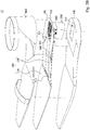
- Fig. 2A depicts a perspective view of a shoe 11 capable of adjusting heel height according to another embodiment of the disclosure.
- Fig. 2B depicts an explosive view of the shoe of Fig. 2A .
- the shoe 11 of the embodiment further includes a shoe body 400, a shoe sole layer 500 and at least one locking mechanism 600.
- the shoe body 400 for example, includes shoe material for fully or partially covering the human foot of the user. Be aware that the shoe body 400 in the disclosure can be generally referred to any appearance of all kind of shoes, and the disclosure is not limited to the style shown in the drawings thereof.
- the shoe plate 100 is disposed between the shoe body 400 and the shoe sole layer 500, and respectively connected to the shoe body 400 and the shoe sole layer 500.
- the shoe sole layer 500 is formed with a penetrating opening 510 which is aligned with the rear bracket 120.
- the retractable shoe-heel 200 extends outwards from the shoe sole layer 500 via the penetrating opening 510.
- the locking mechanism 600 is connected to the shoe plate 100 so as to removably fix the retractable shoe-heel 200 for limiting the telescoping degree of the retractable shoe-heel 200 and determining the current length of the retractable shoe-heel 200.
- the shoe sole layer 500 further covers the locking mechanism 600, the linking member 300 and a part of the shoe plate 100 therein.
- the disclosure is not limited thereto.
- the shoe plate 100 is provided with an upper side face101 and a lower side face 102 which are arranged oppositely with each other.
- the shoe body 400 is disposed on the upper side face 101 of the shoe plate 100, and the retractable shoe-heel 200, the linking member 300 and the shoe sole layer 500 are collectively disposed on the lower side face 102.
- the rear bracket 120 of the shoe plate 100 is further formed with a recess 121.
- the recess 121 exposes a part of the sole layer 500 and the penetrating opening 510.
- the linking member 300 is further formed with a break 301 exposing the penetrating opening 510 and the recess 121, and the retractable shoe-heel 200 is received within the penetrating opening 510, the recess 121 and the break 301.
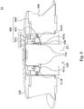
- Fig. 3 depicts an operation schematic view of the shoe 11 of Fig. 2A .
- Fig. 4 depicts a schematic view of a retractable shoe-heel 200 of Fig. 2A .
- the telescopic support member 220 includes a plurality of sleeves 221.
- the sleeves 221 are concentrically arranged with each other and are telescopically sleeved one another in sequence in the major axis direction LA of the telescopic support member 220.
- each of the sleeves 221 is formed with a through space 222 therein, that is, each of the sleeves 221 surrounds its through space 222.
- any two adjacent sleeves 221 one of the sleeves 221 is received within the through space 222 of the other sleeve 221.
- the sizes of these sleeves 221 are gradually increased from large to small.
- the disclosure is not limited thereto, as long as the sleeves can be sequentially sleeved, the sleeves are not limited to be in a same appearance type.
- the telescopic linkage rack can fix several or all of the sleeves sequentially, the telescopic linkage rack does not have to be received inside the telescopic support member.
- the telescopic linkage rack can be placed outside the telescopic support abreast (not shown).
- the telescopic linkage rack 210 includes a plurality of first connecting rods 211, a plurality of second connecting rods 212, a plurality of first shaft pins 213 and a plurality of second shaft pins 214.
- Each of the first connecting rods 211 and each of the second connecting rods 212 which are adjacent with each other are crossed to be pivotally connected to each other through one of the first shaft pins 213.
- the first connecting rods 211 and the second connecting rods 212 are further pivotally connected to one another with an end-to-end manner through the second shaft pins 214.
- the first connecting rods 211 are parallel one another, however, these first connecting rods 211 are not limited to be in the same length or the same type.
- the second connecting rods 212 are parallel one another, however, these second connecting rods 212 are not limited to be in the same length or the same type. Also, the first connecting rods 211 and the second connecting rods 212 are not limited to be in the same length or the same type.
- the length of the telescopic linkage rack 210 is correspondingly changed (e.g., reduced or enlarged).
- the telescopic linkage rack 210 is located in the through space 222 of the innermost one of the sleeves 221, and several or all of the first shaft pins 213 are respectively fixedly connected to several or all of the sleeves 221 along the major axis direction LA of the telescopic linkage rack 210 sequentially, thus, the telescopic support member 220 can be simultaneously telescoped in the same direction and in the same proportion with the telescoping degree of the telescopic linkage rack 210.
- each of the remaining of the sleeves 221 is respectively provided with a slit 223.
- the slits 223 of the sleeves 221 are gradually changed from small to large in length.
- one of the first connecting rods (e.g., the first connecting rods 211A closest to the shoe body 400) is symmetrically pivotally connected to the rear bracket 120 through two shaft pins (e.g., the first shaft pin 213A and the second shaft pin 214A).
- the rear bracket 120 is rotated relative to the front bracket 110 to collectively move the telescopic linkage rack 210 to telescope in the gravity direction GV, because the rear bracket 120 only moves the first connecting rods 211A to be rotated, the second connecting rods 212A can only move with the first connecting rods 211A, and the first connecting rods 211A and the second connecting rods 212A are not rotated at the same angle at the same time.
- the telescopic linkage rack 210 and the telescopic support member 220 can be prevented from being telescopic in the gravity direction, therefore, the lengths of the telescopic linkage rack 210 and the telescopic support member 220 (i.e., retractable shoe-heel 200) which are exposed outwards from the shoe 10 can be fixed.
- the outermost sleeve 221 is formed with a plurality of securing holes 224.
- the securing holes 224 are arranged on the outermost sleeve 221 along an arc-lined arrangement which matches the trajectory curvature of the displacement of the telescopic linkage rack 210.
- each of the securing holes 224 corresponds to one of various lengths that the telescopic linkage rack 210 is able to be changed correspondingly, for example, the telescopic support member 220 has four securing holes 224.
- each of the securing holes 224 is plugged for limiting the displacement of the telescopic linkage rack 210, four different lengths of the retractable heel 200 which are extended outwardly can be provided.
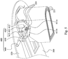
- Fig. 5 depicts a schematic view of a locking mechanism 600 of Fig. 2A .
- Fig. 6 depicts an operation schematic view of the locking mechanism 600 of the shoe 11 capable of adjusting heel height according to the embodiment of the disclosure.
- two locking mechanisms 600 are respectively disposed on the two opposite sides of the shoe plate 100.
- Each of the locking mechanism 600 includes a frame body 610, a spring 630 and an operating portion 640.
- the frame body 610 is provided with a first end 611, a second end 613 and a pivotal portion 612.
- the pivotal portion 612 is disposed between the first end 611 and the second end 613, and is pivotally connected to the rear bracket 120 to each other so that the frame body 610 can be rotated according to the pivotal portion 612.
- One surface 611a of the first end 611 of the frame body 610 is provided with a fixing pin 620.
- the fixing pin 620 is pluggably inserted in one of the securing holes 224.
- the spring 630 is connected to a stationary member (e.g., the sole layer 500) and the other surface 611b of the first end 611 of the frame 610 for pushing the fixing pin 620 back into the securing hole 224.
- One end of the operating portion 640 is abutted against the second end 613 of the frame body 610, and the other end of the operating portion 640 is exposed outwards from the shoe 11.
- the spring 630 continues to abut against the fixing pin 620 for being inserted into one of the securing holes 224, since the movement of the sleeve 221 is restricted by the fixing pin 620, the length of the telescopic linkage rack 210 which can be changed is also limited.
- each of the operating portions 640 rotates the frame body 610 so as to withdraw the fixing pin 620 back from the securing hole 224 with the rotation of the frame body 610.
- the disclosure is not limited thereto, except the locking mechanism 600 having the frame body 610, the spring 630, and the operating portion 640 therein, as long as the telescopic support member 220 can be limited to determine the length of the telescopic support member 220 correspondingly, any specific form of the locking mechanism is not limited in the disclosure.
- the locking mechanism includes a fixing pin (not shown).
- the fixing pin is a separate object, and the fixing pin is pluggably inserted into one of the fixing holes independently for restricting the movement of the sleeves.
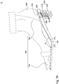
- Fig. 7A- Fig. 7C depict continuous operation schematic views of the shoe 11 capable of adjusting heel height according to the embodiment of the disclosure.
- the shoe body 400 and the show plate 100 mutually define a space for accommodating a single human foot 700.
- the human foot 700 of the user is substantially placed on the shoe plate 100 in which the front bracket 110 bears the toe part 710 of the human foot 700, and the rear bracket 120 bears the heel part 720 of the human foot 700.
- the user first presses the operating portions 640 of the locking mechanisms 600 to withdraw the fixing pin 620 back from the securing hole 224 thereby releasing the restriction for the telescoping of the telescopic support member 220 (refer to Fig. 6 ); next, as shown in Fig. 7B , the user lifts the heel part 720 to bend the toe part 710 in a certain angle so as to decrease the included angle ⁇ between the front bracket 110 and the rear bracket 120.
- the fixing pin 620 withdrawn out from the securing hole 224 starts to slide on the surface of the outermost sleeve 221; after the fixing pin 620 extends into another securing hole 224 again, another length of the retractable shoe-heel 200 exposed outwardly can be determined.
- FIG. 7C or FIG. 3 when a larger heel height is required, the user can continue to bend the toe part 710 to reduce the included angle ⁇ between the rear bracket 120 and the front bracket 110, so that the length of the retractable shoe-heel 200 can be increased again.
- the extending length of the telescopic support member in the embodiment can be controlled to meet the user's requirements in accordance with the bending degrees of the shoe plate, thereby solving the problem that the user must have high-heel shoes with different heel heights at the same time.
- retractable shoe-heel, the linking member, the front bracket, the rear bracket, the first to fourth pivots and the lock mechanism illustrated above are only exemplary, not limitations to the disclosure of the invention according to the appended claims.
- One with ordinary skill in the field of the disclosure may adjust the number of the aforementioned elements according to the actual requirements.
Landscapes
- Health & Medical Sciences (AREA)
- Epidemiology (AREA)
- General Health & Medical Sciences (AREA)
- Public Health (AREA)
- Footwear And Its Accessory, Manufacturing Method And Apparatuses (AREA)
Claims (6)
- Schuh (10), der imstande ist, eine Fersenhöhe anzupassen, mit:einem vorderen Träger (110);einem hinteren Träger (120), der mit dem vorderen Träger (110) drehbar verbunden ist;einem teleskopischen Gestänge (210), das mit dem hinteren Träger (120) schwenkbar verbunden ist und dazu ausgebildet ist, mit der Bewegung des hinteren Trägers (120) teleskopiert zu werden;einem teleskopischen Stützbauteil (220), das mit dem teleskopischen Gestänge (210) fest verbunden ist und dazu ausgebildet ist, in derselben Richtung und in derselben Proportion mit dem Teleskopiergrad des teleskopischen Verbindunggestells (210) simultan teleskopiert zu werden;einem Verbindungsbauteil (300), das mit dem vorderen Träger (110) und dem teleskopischen Stützbauteil (220) schwenkbar verbunden ist und zu dem hinteren Träger (120) beabstandet angeordnet ist; undeinem Arretierungsmechanismus (600), der dazu ausgebildet ist, das teleskopische Stützbauteil (220) zum Begrenzen des Teleskopierens des teleskopischen Stützbauteils (220) entfernbar zu fixieren, dadurch gekennzeichnet, dass das teleskopische Verbindunggestell (210) eine Mehrzahl erster Schaftstifte (213) und eine Mehrzahl zweiter Schaftstifte (214); eine Mehrzahl erster Verbindungsstangen (211), die parallel zueinander sind; und eine Mehrzahl zweiter Verbindungsstangen (212), die parallel zueinander sind, aufweist, bei denen jede der Mehrzahl erster Verbindungsstangen (211) und jede der Mehrzahl zweiter Verbindungsstangen (212), die aneinander angrenzen, gekreuzt sind, so dass sie durch einen der Mehrzahl erster Schaftstifte (213) schwenkbar miteinander verbunden sind, und die Mehrzahl erster Verbindungsstangen (211) und die Mehrzahl zweiter Verbindungsstangen (212) ferner mit einer Ende-an-Ende-Weise durch die Mehrzahl zweiter Schaftstifte (214) schwenkbar miteinander verbunden sind,bei dem, wenn die Mehrzahl erster Verbindungsstangen (211) und die Mehrzahl zweiter Verbindungsstangen (212) dazu ausgebildet sind, zum graduellen Ändern von Lücken zwischen der Mehrzahl erster Schaftstifte (213) voneinander gedreht zu werden, die Länge des teleskopischen Gestänges (210) entsprechend geändert wird;bei dem der hintere Träger (120) mit einer der Mehrzahl erster Verbindungsstangen (211) durch einen der Mehrzahl erster Schaftstifte (213) und einen der Mehrzahl zweiter Schaftstifte (214) schwenkbar verbunden ist, undbei dem, wenn der hintere Träger (120) das teleskopische Gestänge (210) zum entsprechenden Ändern der Länge des teleskopischen Gestänges (210) bewegt, das teleskopische Gestänge (210) lateral bewegt wird.
- Schuh (10), der imstande ist, eine Fersenhöhe anzupassen, nach Anspruch 1, dadurch gekennzeichnet, dass das teleskopische Stützbauteil (220) eine Mehrzahl von Hülsen (221) aufweist, die Mehrzahl von Hülsen (221) konzentrisch angeordnet und in Reihenfolge teleskopisch ineinandergeschoben ist,
bei dem mindestens zwei der Mehrzahl erster Schaftstifte (213) mit mindestens zweien der Mehrzahl von Hülsen (221) in Reihenfolge entlang einer Hauptachsenrichtung des teleskopische Stützbauteils (220) fest verbunden sind. - Schuh (10), der imstande ist, eine Fersenhöhe anzupassen, nach Anspruch 2, dadurch gekennzeichnet, dass die innerste der Mehrzahl von Hülsen (221) mit einem Durchgangsraum (222) darin ausgebildet ist, und das teleskopische Gestänge (210) innerhalb des Durchgangsraums (222) aufgenommen ist.
- Schuh (10), der imstande ist, eine Fersenhöhe anzupassen, nach Anspruch 2, dadurch gekennzeichnet, dass die äußerste der Mehrzahl von Hülsen (221) mit einer Mehrzahl von Sicherungslöchern (224) ausgebildet ist, bei dem die Mehrzahl von Sicherungslöchern (224) entlang einer Bogenlinienanordnung angeordnet ist, bei dem jedes der Mehrzahl von Sicherungslöchern (224) einer verschiedener Längen, in der das teleskopische Gestänge (210) entsprechend geändert werden kann, entspricht; und
der Arretierungsmechanismus (600) einen Fixierungsstift (620) aufweist, der Fixierungsstift (620) in eines der Mehrzahl von Sicherungslöchern (224) zum Fixieren der Mehrzahl von Hülsen (221) zum Bestimmen einer der verschiedenen Längen, in der das teleskopische Gestänge (210) entsprechend geändert werden kann, steckbar eingefügt wird. - Schuh (10), der imstande ist, eine Fersenhöhe anzupassen, nach Anspruch 4, dadurch gekennzeichnet, dass der Arretierungsmechanismus (600) ferner aufweist:einen Rahmenkörper (610), der ein erstes Ende (611), ein zweites Ende (613) und einen Schwenkabschnitt (612), der zwischen dem ersten Ende (611) und dem zweiten Ende (613) angeordnet ist, aufweist, bei dem der Fixierungsstift (620) auf dem ersten Ende (611) des Rahmenkörpers (610) angeordnet ist;eine Feder (630), die mit dem ersten Ende (611) des Rahmenkörpers (610) verbunden ist, zum Drücken des Fixierungsstifts (620) zurück zu dem einen der Mehrzahl von Sicherungslöchern (224); undeinen Betätigungsabschnitt (640), in dem ein Ende des Betätigungsabschnitts (640) an dem zweiten Ende (613) des Rahmenkörpers (610) anliegt, und das andere Ende des Betätigungsabschnitts (640) von dem Schuh (10) nach außen freigelegt ist,bei dem, wenn der Betätigungsabschnitt (640) den Rahmenkörper (610) dreht, der Fixierungsstift (620) von dem einen der Mehrzahl von Sicherungslöchern (224) mit der Drehung des Rahmenkörpers (610) zum Lösen aus einer Fixierung der Mehrzahl von Hülsen (221) zurückgezogen wird.
- Schuh (10), der imstande ist, eine Fersenhöhe anzupassen, nach Anspruch 1, dadurch gekennzeichnet, dass ein Ende des vorderen Trägers (110) mit einer vorstehenden Rippe (111) versehen ist, der hintere Träger (120) mit dem einen Ende des vorderen Trägers (110) durch mindestens einen ersten Drehpunkt (R1) schwenkbar verbunden ist und mit dem teleskopischen Gestänge (210) durch mindestens zwei zweite Drehpunkte (R2) schwenkbar verbunden ist, das Verbindungsbauteil (300) mit der vorstehenden Rippe (111) durch mindestens einen dritten Drehpunkt (R3) schwenkbar verbunden ist, und mit dem teleskopischen Stützbauteil (220) durch mindestens einen vierten Drehpunkt (R4) schwenkbar verbunden ist,
bei dem eine Gestängeeinschränkungsanordnung durch die vorstehende Rippe (111) des vorderen Trägers (110), den hinteren Träger (120), das teleskopische Gestänge (210), das teleskopische Stützbauteil (220) und das Verbindungsbauteil (300) kollektiv definiert ist, und der mindestens eine erste Drehpunkt (R1), die mindestens zwei zweiten Drehpunkte (R2), der mindestens eine dritte Drehpunkt (R3) und der mindestens eine vierte Drehpunkt (R4) parallel zueinander sind.
Applications Claiming Priority (2)
| Application Number | Priority Date | Filing Date | Title |
|---|---|---|---|
| CN201610268734.7A CN107307507B (zh) | 2016-04-27 | 2016-04-27 | 可调整鞋跟高度的鞋子 |
| PCT/CN2016/083143 WO2017185439A1 (zh) | 2016-04-27 | 2016-05-24 | 可调整鞋跟高度的鞋子 |
Publications (3)
| Publication Number | Publication Date |
|---|---|
| EP3449752A1 EP3449752A1 (de) | 2019-03-06 |
| EP3449752A4 EP3449752A4 (de) | 2020-01-01 |
| EP3449752B1 true EP3449752B1 (de) | 2021-04-14 |
Family
ID=60160596
Family Applications (1)
| Application Number | Title | Priority Date | Filing Date |
|---|---|---|---|
| EP16899949.8A Active EP3449752B1 (de) | 2016-04-27 | 2016-05-24 | Schuhe mit höhenverstellbaren absätzen |
Country Status (5)
| Country | Link |
|---|---|
| US (1) | US11197516B2 (de) |
| EP (1) | EP3449752B1 (de) |
| JP (1) | JP6664504B2 (de) |
| CN (1) | CN107307507B (de) |
| WO (1) | WO2017185439A1 (de) |
Families Citing this family (5)
| Publication number | Priority date | Publication date | Assignee | Title |
|---|---|---|---|---|
| CN109171100B (zh) * | 2018-09-26 | 2021-05-11 | 宝昂(福建)鞋服有限公司 | 可伸缩高跟鞋 |
| CN109156929B (zh) * | 2018-09-26 | 2021-06-01 | 宝昂(福建)鞋服有限公司 | 后跟可翻转高跟鞋 |
| US20200268102A1 (en) * | 2019-02-26 | 2020-08-27 | Mona Carter | Convertible Shoe Assembly |
| JP6631898B1 (ja) * | 2019-04-06 | 2020-01-15 | 大司朗 高橋 | 履物およびかかと構造 |
| US11903450B1 (en) | 2022-10-12 | 2024-02-20 | Esbeyda Del Rio | Selectively height adjustable platform shoe assembly and method of use |
Family Cites Families (28)
| Publication number | Priority date | Publication date | Assignee | Title |
|---|---|---|---|---|
| US3929139A (en) * | 1974-12-27 | 1975-12-30 | Nathan Salzman | Corrective shoe device |
| FR2491740B1 (fr) * | 1980-10-09 | 1986-04-04 | Sarkissian Vahe | Ensemble semelle et talon pour chaussure a cambrure variable |
| US6021586A (en) * | 1997-12-02 | 2000-02-08 | Bucalo; Gladys Lopez | Adjustable heel assembly and shoe including the same |
| US5887360A (en) * | 1997-12-02 | 1999-03-30 | Bucalo; Gladys Lopez | Adjustable heel assembly and shoe including the same |
| CN2376763Y (zh) * | 1999-07-16 | 2000-05-10 | 吴宁 | 一种鞋跟高度可调的鞋 |
| KR100442189B1 (ko) | 2001-03-26 | 2004-07-30 | 박점권 | 신발 뒷굽의 높이 조절장치 |
| AU2002362078A1 (en) * | 2001-12-07 | 2003-06-23 | Riccardo W Hayes | Devices and systems for dynamic foot support |
| US6684531B2 (en) * | 2001-12-27 | 2004-02-03 | Brian G. Rennex | Spring space shoe |
| US20050166422A1 (en) * | 2004-02-04 | 2005-08-04 | Puma Aktiengesellschaft Rudolf Dassler Sport | Shoe with an articulated spring-loaded outsole |
| WO2009030017A1 (en) * | 2007-09-06 | 2009-03-12 | Powerdisk Development Ltd. | Energy storage and return spring |
| KR100954343B1 (ko) * | 2008-01-16 | 2010-04-21 | 정만호 | 다기능을 겸비한 키높이 조절 신발 |
| US20100146817A1 (en) * | 2008-12-17 | 2010-06-17 | Crisp Enterprises, Inc. | Footwear Having Adjustable-Height Heel and Method Therefor |
| EP2421396A2 (de) * | 2009-04-24 | 2012-02-29 | Veronica Haupt | Absatz für einen schuh |
| US20110119954A1 (en) * | 2009-11-24 | 2011-05-26 | Sandrysabel Ortiz | Replaceable Heels |
| FR2959646B1 (fr) * | 2010-05-05 | 2013-04-26 | Vahe Sarkissian | Chaussure feminine a plusieurs hauteurs. |
| FR2972906B1 (fr) * | 2011-03-25 | 2014-05-16 | Gecis | Chaussure a amorti et propulsion ameliores |
| US9750300B2 (en) * | 2011-12-23 | 2017-09-05 | Nike, Inc. | Article of footwear having an elevated plate sole structure |
| CN202680689U (zh) * | 2012-03-25 | 2013-01-23 | 谭纲兴 | 一种高度可调鞋跟 |
| KR20130006105U (ko) * | 2012-04-13 | 2013-10-22 | 김영도 | 굽 높이 조절 신발 |
| US20150157087A1 (en) * | 2012-06-13 | 2015-06-11 | Elevate Fashion Ltd. | Adjustable shoe |
| DE102012213809B4 (de) * | 2012-08-03 | 2016-01-21 | Flexheel Gmbh | Sohlenteil |
| KR200468008Y1 (ko) * | 2012-10-26 | 2013-07-17 | 박홍범 | 높낮이 조절형 작업화 |
| CN203290309U (zh) * | 2013-05-14 | 2013-11-20 | 温州职业技术学院 | 一种可调节鞋跟高度的鞋 |
| CN103238981A (zh) * | 2013-05-14 | 2013-08-14 | 温州职业技术学院 | 一种可调节鞋跟高度的鞋 |
| CN106572719B (zh) * | 2014-08-11 | 2021-06-01 | 钱德妮·塞西 | 可适配鞋具 |
| CN205093678U (zh) * | 2015-10-26 | 2016-03-23 | 何凯峰 | 可调节鞋跟高度的高跟鞋 |
| TWM516337U (zh) * | 2015-11-04 | 2016-02-01 | Big Hill Ind Co Ltd | 足弓調整裝置 |
| CN205568038U (zh) * | 2016-04-27 | 2016-09-14 | 江宗儒 | 可调整鞋跟高度的鞋子 |
-
2016
- 2016-04-27 CN CN201610268734.7A patent/CN107307507B/zh active Active
- 2016-05-24 JP JP2018540752A patent/JP6664504B2/ja active Active
- 2016-05-24 WO PCT/CN2016/083143 patent/WO2017185439A1/zh not_active Ceased
- 2016-05-24 US US16/085,593 patent/US11197516B2/en active Active
- 2016-05-24 EP EP16899949.8A patent/EP3449752B1/de active Active
Non-Patent Citations (1)
| Title |
|---|
| None * |
Also Published As
| Publication number | Publication date |
|---|---|
| JP6664504B2 (ja) | 2020-03-13 |
| CN107307507B (zh) | 2020-10-13 |
| WO2017185439A1 (zh) | 2017-11-02 |
| JP2019503811A (ja) | 2019-02-14 |
| CN107307507A (zh) | 2017-11-03 |
| EP3449752A1 (de) | 2019-03-06 |
| EP3449752A4 (de) | 2020-01-01 |
| US20190110555A1 (en) | 2019-04-18 |
| US11197516B2 (en) | 2021-12-14 |
Similar Documents
| Publication | Publication Date | Title |
|---|---|---|
| EP3449752B1 (de) | Schuhe mit höhenverstellbaren absätzen | |
| US9289025B2 (en) | Flat-to-heel convertible outsole | |
| EP3434133B1 (de) | Schuh, der um verwandelt werden kann | |
| EP3133949B1 (de) | Zusammenklappbarer schuhabsatz | |
| EP1982608A1 (de) | Unterelement zum Einsetzen in einen Schuh mit einstellbarem Absatz | |
| JP2019500159A (ja) | 幅調整機能を有する履物 | |
| JP2015524739A (ja) | 反発性靴 | |
| US20110061270A1 (en) | Height adjustable shoe heel with damping mechanism | |
| KR101318868B1 (ko) | 사이즈 가변형 신발 | |
| JPH01131602A (ja) | 特にスキーブーツ用の調整装置 | |
| JP2004188195A (ja) | スポーツ靴 | |
| CN205568038U (zh) | 可调整鞋跟高度的鞋子 | |
| CN205585433U (zh) | 可变更鞋种类的鞋子 | |
| GB2511150A (en) | An Adjustable Heel For Footwear | |
| CN110448010A (zh) | 一种脚控方便快速调节高低的可组合的增高鞋 | |
| JP7201308B1 (ja) | 靴 | |
| TWI604801B (zh) | 可調整鞋跟高度的鞋子 | |
| US12285075B2 (en) | Height adjustable shoe heel | |
| TWM535976U (zh) | 可調整鞋跟高度的鞋子 | |
| KR101288183B1 (ko) | 높이 조절이 가능한 구두 | |
| IT202100000269A1 (it) | Calzatura | |
| KR20060013532A (ko) | 조절 가능하고 끼워 맞춤식 스케이트 | |
| JP2020171343A (ja) | 履物およびかかと構造 | |
| KR200348288Y1 (ko) | 롤러 출몰식 활주화 | |
| CN117243444A (zh) | 一种能改变弧度的腰铁 |
Legal Events
| Date | Code | Title | Description |
|---|---|---|---|
| STAA | Information on the status of an ep patent application or granted ep patent |
Free format text: STATUS: THE INTERNATIONAL PUBLICATION HAS BEEN MADE |
|
| PUAI | Public reference made under article 153(3) epc to a published international application that has entered the european phase |
Free format text: ORIGINAL CODE: 0009012 |
|
| STAA | Information on the status of an ep patent application or granted ep patent |
Free format text: STATUS: REQUEST FOR EXAMINATION WAS MADE |
|
| 17P | Request for examination filed |
Effective date: 20181001 |
|
| AK | Designated contracting states |
Kind code of ref document: A1 Designated state(s): AL AT BE BG CH CY CZ DE DK EE ES FI FR GB GR HR HU IE IS IT LI LT LU LV MC MK MT NL NO PL PT RO RS SE SI SK SM TR |
|
| AX | Request for extension of the european patent |
Extension state: BA ME |
|
| DAV | Request for validation of the european patent (deleted) | ||
| DAX | Request for extension of the european patent (deleted) | ||
| A4 | Supplementary search report drawn up and despatched |
Effective date: 20191129 |
|
| RIC1 | Information provided on ipc code assigned before grant |
Ipc: A43B 13/14 20060101ALI20191125BHEP Ipc: A43B 21/24 20060101ALI20191125BHEP Ipc: A43B 21/437 20060101ALI20191125BHEP Ipc: A43B 7/38 20060101ALI20191125BHEP Ipc: A43B 21/42 20060101AFI20191125BHEP |
|
| RIN1 | Information on inventor provided before grant (corrected) |
Inventor name: HUANG, YA-FEN Inventor name: CHIANG, TSUNG-JU |
|
| GRAP | Despatch of communication of intention to grant a patent |
Free format text: ORIGINAL CODE: EPIDOSNIGR1 |
|
| STAA | Information on the status of an ep patent application or granted ep patent |
Free format text: STATUS: GRANT OF PATENT IS INTENDED |
|
| INTG | Intention to grant announced |
Effective date: 20201104 |
|
| GRAS | Grant fee paid |
Free format text: ORIGINAL CODE: EPIDOSNIGR3 |
|
| GRAA | (expected) grant |
Free format text: ORIGINAL CODE: 0009210 |
|
| STAA | Information on the status of an ep patent application or granted ep patent |
Free format text: STATUS: THE PATENT HAS BEEN GRANTED |
|
| AK | Designated contracting states |
Kind code of ref document: B1 Designated state(s): AL AT BE BG CH CY CZ DE DK EE ES FI FR GB GR HR HU IE IS IT LI LT LU LV MC MK MT NL NO PL PT RO RS SE SI SK SM TR |
|
| REG | Reference to a national code |
Ref country code: GB Ref legal event code: FG4D |
|
| REG | Reference to a national code |
Ref country code: CH Ref legal event code: EP |
|
| REG | Reference to a national code |
Ref country code: DE Ref legal event code: R096 Ref document number: 602016056296 Country of ref document: DE |
|
| REG | Reference to a national code |
Ref country code: IE Ref legal event code: FG4D |
|
| REG | Reference to a national code |
Ref country code: AT Ref legal event code: REF Ref document number: 1381470 Country of ref document: AT Kind code of ref document: T Effective date: 20210515 |
|
| REG | Reference to a national code |
Ref country code: LT Ref legal event code: MG9D |
|
| REG | Reference to a national code |
Ref country code: AT Ref legal event code: MK05 Ref document number: 1381470 Country of ref document: AT Kind code of ref document: T Effective date: 20210414 |
|
| REG | Reference to a national code |
Ref country code: NL Ref legal event code: MP Effective date: 20210414 |
|
| PG25 | Lapsed in a contracting state [announced via postgrant information from national office to epo] |
Ref country code: FI Free format text: LAPSE BECAUSE OF FAILURE TO SUBMIT A TRANSLATION OF THE DESCRIPTION OR TO PAY THE FEE WITHIN THE PRESCRIBED TIME-LIMIT Effective date: 20210414 Ref country code: LT Free format text: LAPSE BECAUSE OF FAILURE TO SUBMIT A TRANSLATION OF THE DESCRIPTION OR TO PAY THE FEE WITHIN THE PRESCRIBED TIME-LIMIT Effective date: 20210414 Ref country code: NL Free format text: LAPSE BECAUSE OF FAILURE TO SUBMIT A TRANSLATION OF THE DESCRIPTION OR TO PAY THE FEE WITHIN THE PRESCRIBED TIME-LIMIT Effective date: 20210414 Ref country code: BG Free format text: LAPSE BECAUSE OF FAILURE TO SUBMIT A TRANSLATION OF THE DESCRIPTION OR TO PAY THE FEE WITHIN THE PRESCRIBED TIME-LIMIT Effective date: 20210714 Ref country code: AT Free format text: LAPSE BECAUSE OF FAILURE TO SUBMIT A TRANSLATION OF THE DESCRIPTION OR TO PAY THE FEE WITHIN THE PRESCRIBED TIME-LIMIT Effective date: 20210414 Ref country code: HR Free format text: LAPSE BECAUSE OF FAILURE TO SUBMIT A TRANSLATION OF THE DESCRIPTION OR TO PAY THE FEE WITHIN THE PRESCRIBED TIME-LIMIT Effective date: 20210414 |
|
| PG25 | Lapsed in a contracting state [announced via postgrant information from national office to epo] |
Ref country code: SE Free format text: LAPSE BECAUSE OF FAILURE TO SUBMIT A TRANSLATION OF THE DESCRIPTION OR TO PAY THE FEE WITHIN THE PRESCRIBED TIME-LIMIT Effective date: 20210414 Ref country code: RS Free format text: LAPSE BECAUSE OF FAILURE TO SUBMIT A TRANSLATION OF THE DESCRIPTION OR TO PAY THE FEE WITHIN THE PRESCRIBED TIME-LIMIT Effective date: 20210414 Ref country code: PT Free format text: LAPSE BECAUSE OF FAILURE TO SUBMIT A TRANSLATION OF THE DESCRIPTION OR TO PAY THE FEE WITHIN THE PRESCRIBED TIME-LIMIT Effective date: 20210816 Ref country code: PL Free format text: LAPSE BECAUSE OF FAILURE TO SUBMIT A TRANSLATION OF THE DESCRIPTION OR TO PAY THE FEE WITHIN THE PRESCRIBED TIME-LIMIT Effective date: 20210414 Ref country code: NO Free format text: LAPSE BECAUSE OF FAILURE TO SUBMIT A TRANSLATION OF THE DESCRIPTION OR TO PAY THE FEE WITHIN THE PRESCRIBED TIME-LIMIT Effective date: 20210714 Ref country code: LV Free format text: LAPSE BECAUSE OF FAILURE TO SUBMIT A TRANSLATION OF THE DESCRIPTION OR TO PAY THE FEE WITHIN THE PRESCRIBED TIME-LIMIT Effective date: 20210414 Ref country code: GR Free format text: LAPSE BECAUSE OF FAILURE TO SUBMIT A TRANSLATION OF THE DESCRIPTION OR TO PAY THE FEE WITHIN THE PRESCRIBED TIME-LIMIT Effective date: 20210715 Ref country code: IS Free format text: LAPSE BECAUSE OF FAILURE TO SUBMIT A TRANSLATION OF THE DESCRIPTION OR TO PAY THE FEE WITHIN THE PRESCRIBED TIME-LIMIT Effective date: 20210814 |
|
| REG | Reference to a national code |
Ref country code: DE Ref legal event code: R119 Ref document number: 602016056296 Country of ref document: DE |
|
| REG | Reference to a national code |
Ref country code: CH Ref legal event code: PL |
|
| PG25 | Lapsed in a contracting state [announced via postgrant information from national office to epo] |
Ref country code: ES Free format text: LAPSE BECAUSE OF FAILURE TO SUBMIT A TRANSLATION OF THE DESCRIPTION OR TO PAY THE FEE WITHIN THE PRESCRIBED TIME-LIMIT Effective date: 20210414 Ref country code: RO Free format text: LAPSE BECAUSE OF FAILURE TO SUBMIT A TRANSLATION OF THE DESCRIPTION OR TO PAY THE FEE WITHIN THE PRESCRIBED TIME-LIMIT Effective date: 20210414 Ref country code: MC Free format text: LAPSE BECAUSE OF FAILURE TO SUBMIT A TRANSLATION OF THE DESCRIPTION OR TO PAY THE FEE WITHIN THE PRESCRIBED TIME-LIMIT Effective date: 20210414 Ref country code: LI Free format text: LAPSE BECAUSE OF NON-PAYMENT OF DUE FEES Effective date: 20210531 Ref country code: LU Free format text: LAPSE BECAUSE OF NON-PAYMENT OF DUE FEES Effective date: 20210524 Ref country code: CH Free format text: LAPSE BECAUSE OF NON-PAYMENT OF DUE FEES Effective date: 20210531 Ref country code: EE Free format text: LAPSE BECAUSE OF FAILURE TO SUBMIT A TRANSLATION OF THE DESCRIPTION OR TO PAY THE FEE WITHIN THE PRESCRIBED TIME-LIMIT Effective date: 20210414 Ref country code: DK Free format text: LAPSE BECAUSE OF FAILURE TO SUBMIT A TRANSLATION OF THE DESCRIPTION OR TO PAY THE FEE WITHIN THE PRESCRIBED TIME-LIMIT Effective date: 20210414 Ref country code: CZ Free format text: LAPSE BECAUSE OF FAILURE TO SUBMIT A TRANSLATION OF THE DESCRIPTION OR TO PAY THE FEE WITHIN THE PRESCRIBED TIME-LIMIT Effective date: 20210414 Ref country code: SM Free format text: LAPSE BECAUSE OF FAILURE TO SUBMIT A TRANSLATION OF THE DESCRIPTION OR TO PAY THE FEE WITHIN THE PRESCRIBED TIME-LIMIT Effective date: 20210414 Ref country code: SK Free format text: LAPSE BECAUSE OF FAILURE TO SUBMIT A TRANSLATION OF THE DESCRIPTION OR TO PAY THE FEE WITHIN THE PRESCRIBED TIME-LIMIT Effective date: 20210414 |
|
| REG | Reference to a national code |
Ref country code: BE Ref legal event code: MM Effective date: 20210531 |
|
| PLBE | No opposition filed within time limit |
Free format text: ORIGINAL CODE: 0009261 |
|
| STAA | Information on the status of an ep patent application or granted ep patent |
Free format text: STATUS: NO OPPOSITION FILED WITHIN TIME LIMIT |
|
| 26N | No opposition filed |
Effective date: 20220117 |
|
| PG25 | Lapsed in a contracting state [announced via postgrant information from national office to epo] |
Ref country code: IE Free format text: LAPSE BECAUSE OF NON-PAYMENT OF DUE FEES Effective date: 20210524 Ref country code: DE Free format text: LAPSE BECAUSE OF NON-PAYMENT OF DUE FEES Effective date: 20211201 |
|
| PG25 | Lapsed in a contracting state [announced via postgrant information from national office to epo] |
Ref country code: IS Free format text: LAPSE BECAUSE OF FAILURE TO SUBMIT A TRANSLATION OF THE DESCRIPTION OR TO PAY THE FEE WITHIN THE PRESCRIBED TIME-LIMIT Effective date: 20210814 Ref country code: AL Free format text: LAPSE BECAUSE OF FAILURE TO SUBMIT A TRANSLATION OF THE DESCRIPTION OR TO PAY THE FEE WITHIN THE PRESCRIBED TIME-LIMIT Effective date: 20210414 |
|
| PG25 | Lapsed in a contracting state [announced via postgrant information from national office to epo] |
Ref country code: BE Free format text: LAPSE BECAUSE OF NON-PAYMENT OF DUE FEES Effective date: 20210531 |
|
| PG25 | Lapsed in a contracting state [announced via postgrant information from national office to epo] |
Ref country code: CY Free format text: LAPSE BECAUSE OF FAILURE TO SUBMIT A TRANSLATION OF THE DESCRIPTION OR TO PAY THE FEE WITHIN THE PRESCRIBED TIME-LIMIT Effective date: 20210414 |
|
| PG25 | Lapsed in a contracting state [announced via postgrant information from national office to epo] |
Ref country code: HU Free format text: LAPSE BECAUSE OF FAILURE TO SUBMIT A TRANSLATION OF THE DESCRIPTION OR TO PAY THE FEE WITHIN THE PRESCRIBED TIME-LIMIT; INVALID AB INITIO Effective date: 20160524 |
|
| PG25 | Lapsed in a contracting state [announced via postgrant information from national office to epo] |
Ref country code: MK Free format text: LAPSE BECAUSE OF FAILURE TO SUBMIT A TRANSLATION OF THE DESCRIPTION OR TO PAY THE FEE WITHIN THE PRESCRIBED TIME-LIMIT Effective date: 20210414 |
|
| PG25 | Lapsed in a contracting state [announced via postgrant information from national office to epo] |
Ref country code: TR Free format text: LAPSE BECAUSE OF FAILURE TO SUBMIT A TRANSLATION OF THE DESCRIPTION OR TO PAY THE FEE WITHIN THE PRESCRIBED TIME-LIMIT Effective date: 20210414 |
|
| PG25 | Lapsed in a contracting state [announced via postgrant information from national office to epo] |
Ref country code: MT Free format text: LAPSE BECAUSE OF FAILURE TO SUBMIT A TRANSLATION OF THE DESCRIPTION OR TO PAY THE FEE WITHIN THE PRESCRIBED TIME-LIMIT Effective date: 20210414 |
|
| PGFP | Annual fee paid to national office [announced via postgrant information from national office to epo] |
Ref country code: GB Payment date: 20250522 Year of fee payment: 10 |
|
| PGFP | Annual fee paid to national office [announced via postgrant information from national office to epo] |
Ref country code: IT Payment date: 20250528 Year of fee payment: 10 |
|
| PGFP | Annual fee paid to national office [announced via postgrant information from national office to epo] |
Ref country code: FR Payment date: 20250523 Year of fee payment: 10 |