EP3449130B1 - Cutting assembly for a chopper pump - Google Patents
Cutting assembly for a chopper pump Download PDFInfo
- Publication number
- EP3449130B1 EP3449130B1 EP17790355.6A EP17790355A EP3449130B1 EP 3449130 B1 EP3449130 B1 EP 3449130B1 EP 17790355 A EP17790355 A EP 17790355A EP 3449130 B1 EP3449130 B1 EP 3449130B1
- Authority
- EP
- European Patent Office
- Prior art keywords
- cutting
- insert
- impeller
- extension
- assembly
- Prior art date
- Legal status (The legal status is an assumption and is not a legal conclusion. Google has not performed a legal analysis and makes no representation as to the accuracy of the status listed.)
- Active
Links
- 239000012530 fluid Substances 0.000 description 16
- 239000007787 solid Substances 0.000 description 13
- 238000000034 method Methods 0.000 description 7
- 230000008569 process Effects 0.000 description 7
- 239000000463 material Substances 0.000 description 6
- 230000008878 coupling Effects 0.000 description 5
- 238000010168 coupling process Methods 0.000 description 5
- 238000005859 coupling reaction Methods 0.000 description 5
- 238000005086 pumping Methods 0.000 description 4
- 230000008859 change Effects 0.000 description 3
- 230000009471 action Effects 0.000 description 2
- 230000003993 interaction Effects 0.000 description 2
- 230000007246 mechanism Effects 0.000 description 2
- 230000004048 modification Effects 0.000 description 2
- 238000012986 modification Methods 0.000 description 2
- 241000755266 Kathetostoma giganteum Species 0.000 description 1
- 229910000831 Steel Inorganic materials 0.000 description 1
- 238000002485 combustion reaction Methods 0.000 description 1
- 238000004891 communication Methods 0.000 description 1
- 238000010276 construction Methods 0.000 description 1
- 239000007769 metal material Substances 0.000 description 1
- 125000006850 spacer group Chemical group 0.000 description 1
- 239000010959 steel Substances 0.000 description 1
- 239000011800 void material Substances 0.000 description 1
Images


Classifications
-
- F—MECHANICAL ENGINEERING; LIGHTING; HEATING; WEAPONS; BLASTING
- F04—POSITIVE - DISPLACEMENT MACHINES FOR LIQUIDS; PUMPS FOR LIQUIDS OR ELASTIC FLUIDS
- F04D—NON-POSITIVE-DISPLACEMENT PUMPS
- F04D7/00—Pumps adapted for handling specific fluids, e.g. by selection of specific materials for pumps or pump parts
- F04D7/02—Pumps adapted for handling specific fluids, e.g. by selection of specific materials for pumps or pump parts of centrifugal type
- F04D7/04—Pumps adapted for handling specific fluids, e.g. by selection of specific materials for pumps or pump parts of centrifugal type the fluids being viscous or non-homogenous
- F04D7/045—Pumps adapted for handling specific fluids, e.g. by selection of specific materials for pumps or pump parts of centrifugal type the fluids being viscous or non-homogenous with means for comminuting, mixing stirring or otherwise treating
-
- F—MECHANICAL ENGINEERING; LIGHTING; HEATING; WEAPONS; BLASTING
- F04—POSITIVE - DISPLACEMENT MACHINES FOR LIQUIDS; PUMPS FOR LIQUIDS OR ELASTIC FLUIDS
- F04D—NON-POSITIVE-DISPLACEMENT PUMPS
- F04D29/00—Details, component parts, or accessories
- F04D29/18—Rotors
- F04D29/22—Rotors specially for centrifugal pumps
- F04D29/2261—Rotors specially for centrifugal pumps with special measures
- F04D29/2288—Rotors specially for centrifugal pumps with special measures for comminuting, mixing or separating
-
- F—MECHANICAL ENGINEERING; LIGHTING; HEATING; WEAPONS; BLASTING
- F04—POSITIVE - DISPLACEMENT MACHINES FOR LIQUIDS; PUMPS FOR LIQUIDS OR ELASTIC FLUIDS
- F04D—NON-POSITIVE-DISPLACEMENT PUMPS
- F04D29/00—Details, component parts, or accessories
- F04D29/18—Rotors
- F04D29/22—Rotors specially for centrifugal pumps
- F04D29/2261—Rotors specially for centrifugal pumps with special measures
- F04D29/2294—Rotors specially for centrifugal pumps with special measures for protection, e.g. against abrasion
-
- F—MECHANICAL ENGINEERING; LIGHTING; HEATING; WEAPONS; BLASTING
- F04—POSITIVE - DISPLACEMENT MACHINES FOR LIQUIDS; PUMPS FOR LIQUIDS OR ELASTIC FLUIDS
- F04D—NON-POSITIVE-DISPLACEMENT PUMPS
- F04D29/00—Details, component parts, or accessories
- F04D29/26—Rotors specially for elastic fluids
- F04D29/28—Rotors specially for elastic fluids for centrifugal or helico-centrifugal pumps for radial-flow or helico-centrifugal pumps
Definitions
- the present invention relates generally to a chopper pump for pumping fluids containing solid matter and, more specifically, to a cutting assembly for breaking up solid matter in the fluid being supplied to the chopper pump into smaller pieces.
- Chopper pumps are implemented when a fluid supply contains solid matter that needs to be pumped, or displaced.
- the fluid supply is provided to an inlet of the chopper pump where an impeller rotates adjacent to a cutting plate that may be hardened. Rotation of the impeller adjacent to the cutting plate engages the solid matter and displaces the fluid supply from the inlet to an outlet.
- chopper pumps include a hardened impeller to aid in cutting the solid matter and increase the durability of the impeller.
- hardening an impeller inhibits the ability of a user to trim ( i . e .., remove material from) the impeller to customize pump performance and/or contour the ultimate form factor of the impeller.
- solid matter can become stuck or lodged between the impeller and the cutting plate during operation of the chopper pump, which leads to clogging and/or reduced pump efficiency.
- US2014/377055A1 describes a centrifugal pump with a cutter mechanism having a toothed cutter auger affixed to an impeller, and a toothed cutter stator affixed to the volute casing.
- the auger is a rotor cutter profiled radially to match the inlet geometry of the impeller vanes while extending along its central axis towards the pump suction.
- the auger is radially concentric to the impeller and includes vanes numbered to match the number of vanes on the impeller.
- the auger is affixed to the impeller, with a lockscrew threaded into a common pump shaft.
- the radial profile of the auger makes a continuous vane with the impeller, and prevents solids from hanging on the inlet vane tip or center void.
- a cutting assembly for a chopper pump having a cutting insert removably received within a recess in an impeller and arranged adjacent to a cutting plate.
- the cutting insert is a separate component from the impeller, which negates the desire for the entire impeller to be fabricated from a hardened material.
- the cutting assembly disclosed allows the discrete cutting insert to be fabricated from a hardened material enabling the impeller, which may not be hardened in certain situations, to be trimmed or modified, if desired.
- the cutting plate includes one or more cutting plate grooves to aid in removing solid matter that could get stuck between the cutting blade insert and the cutting plate.
- Some embodiments of the invention provide a cutting assembly for a chopper pump.
- the cutting assembly includes a cutting insert having a cutting blade extending radially therefrom, and an impeller having a central hub, a plurality of vanes, and an insert surface.
- the insert surface defines an axial recess that is dimensioned to receive the cutting insert therein.
- the cutting assembly further includes a cutting plate having a plate hub with a cutting extension protruding radially inward therefrom. Rotation of the impeller rotates the cutting blade past the cutting extension.
- a chopper pump including a drive section having a drive shaft, and a housing coupled to the drive section and having an inlet, an outlet, and an internal cavity arranged between the inlet and the outlet.
- the chopper pump further includes an impeller received within the internal cavity and coupled to the drive shaft for rotation therewith.
- the impeller includes a recess formed therein.
- the chopper pump further includes a cutting insert received within the recess of the impeller and having a cutting blade, and a cutting plate coupled to the housing within the internal cavity.
- the cutting plate includes a cutting extension that extends radially inward. Rotation of the impeller rotates the cutting blade past the cutting extension.
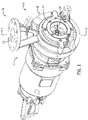
- FIG. 1 illustrates a chopper pump 10 according to one embodiment of the invention.
- the chopper pump 10 includes a drive section 12 coupled to an inlet section 14.
- the inlet section 14 includes a housing 16 having an inlet 18 and an outlet 20.
- the chopper pump 10 furnishes a process fluid from the inlet 18 of the housing 16 to the outlet 20 of the housing 16, as will be described in detail below.
- the drive section 12 includes a drive shaft 22 extending through the drive section 12.
- the drive shaft 22 may extend through one or more bearings (not shown) and may be coupled to a driving mechanism (e.g ., an electric motor or an internal combustion engine) that rotates the drive shaft 22 in a desired direction for pumping of the supply fluid from the inlet 18 to the outlet 20.
- a driving mechanism e.g ., an electric motor or an internal combustion engine
- the housing 16 defines an internal cavity 24 in fluid communication with the inlet 18 and the outlet 20.
- a cutting assembly 26 is configured to be arranged within the internal cavity 24 of the housing 16.
- the cutting assembly 26 includes a cutting insert 28, an impeller 30, and a cutting plate 32.
- the cutting insert 28 is releasably coupled to the impeller 30 and is arranged adjacent to the cutting plate 32.
- the cutting insert 28 and the impeller 30 are fastened to the drive shaft 22 via an impeller fastening element 34 in the form of a threaded bolt. This enables the impeller 30 and the cutting insert 28 to rotate with the drive shaft 22 in a desired direction.
- the cutting insert 28 includes a plurality of cutting blades 36 extending generally radially from and arranged circumferentially around an insert central hub 38.
- the plurality of cutting blades 36 define a substantially curved shape and include a mounting aperture 40 extending therethrough.
- the mounting apertures 40 are arranged adjacent to the insert central hub 38.
- the cutting insert 28 is preferably fabricated from a hardened metal material (e.g., 440SST, PH grades of stainless, such as, 17-7PH, 17-5PH, and 15-5PH, as well as other hardenable steels).
- a hardness of the cutting plate 28 can be greater ( i.e ., harder) than a hardness of the impeller 30.
- the insert central hub 38 includes a first protrusion 42 extending substantially perpendicularly from a proximal end of the plurality of cutting blades 36 in a first direction, and a second protrusion 44 extending substantially perpendicularly from the proximal end of the plurality of cutting blades 36 in a second direction opposite the first direction.
- the illustrated impeller 30 is in the form of a semi-open impeller. In other embodiments, the impeller 30 may be in the form of an open impeller or any other form capable of receiving a cutting insert.
- the impeller 30 includes a shroud 46 having a first shroud surface 48 and an opposing second shroud surface 50.
- a plurality of vanes 52 extend from and are arranged circumferentially around the first shroud surface 48 of the impeller 30.
- the plurality of vanes 52 define a substantially curved shape that curves from a shroud outer surface 54 of the shroud 46 toward a central hub 56 of the impeller 30.
- the curvature defined by the plurality of vanes 52 is similar to the curvature defined by the plurality of cutting blades 36 (as shown in FIG.
- the plurality of vanes 52 may define an alternative shape, for example a substantially straight, or linear, shape between the shroud outer surface 54 and the central hub 56.
- the illustrated impeller 30 includes four vanes 52. In other embodiments, the impeller 30 may include more or less than four vanes 52.
- the central hub 56 of the impeller 30 includes a recess 58 defined by an insert surface 60 that is axially recessed and dimensioned to receive the cutting insert 28.
- the recess 58 is dimensioned to accommodate the cutting insert 28 therein.
- the insert surface 60 extends from the central hub 56 partially along each of the plurality of vanes 52. That is, each of the plurality of vanes 52 defines a step change in an axial dimension at a location between the shroud outer surface 54 and the central hub 56. The location at which the step change in axial dimension occurs in each of the plurality of vanes 52 is congruent with a distance that the plurality of cutting blades 36 radially extend from the insert central hub 38 of the cutting insert 28.
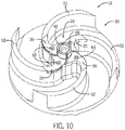
- an axial depth of the recess 58 (i . e ., the magnitude of the step change in axial dimension of the plurality of vanes 52) is congruent with a thickness of the plurality of cutting blades 36. In this way, when the cutting insert 28 is inserted into the recess 58 of the impeller 30 (as shown in FIG. 10 ), the plurality of cutting blades 36 are arranged flush with the plurality of vanes 52.
- the insert surface 60 includes a plurality of insert apertures 62 recessed into the insert surface 60 and arranged circumferentially around a central hub aperture 64 of the central hub 56.
- the plurality of insert apertures 62 are each dimensioned to threadably received a fastening element 65, which may be in the form of an flathead cap screw or bolt.
- the plurality of insert apertures 62 are arranged to align with the mounting apertures 40 of the cutting insert 28.
- the insert apertures 62 are configured to align with the mounting apertures 40 to enable the fastening elements 65 to extend through the mounting apertures 40 and thread into the insert apertures 62.
- the central hub aperture 64 is dimensioned to receive the backward second protrusion 44 of the insert central hub 38.
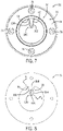
- the cutting plate 32 includes a cutting extension 66 protruding radially inward from an inner surface 68 of a plate hub 70.
- the illustrated cutting plate 32 includes one cutting extension 66 arranged on the inner surface 68 of the plate hub 70.
- the cutting plate 32 may include more than one cutting extensions 66 arranged circumferentially around the inner surface 68.
- the cutting plate 32 may include two cutting extensions 66 arranged circumferentially in approximately 180 degree increments on the inner surface 68.
- the cutting plate 32 may include three cutting extensions 66 arranged circumferentially in approximately 120 degree increments on the inner surface 68.
- the inner surface 68 of the plate hub 70 defines an opening with a diameter that is substantially equal to a diameter of the inlet 18 of the housing 16.
- the plate hub 70 extends substantially perpendicularly from a base 72 of the cutting plate 32.
- the base 72 of the cutting plate 32 includes a mounting surface 74 having a plurality of threaded mounting apertures 76 arranged circumferentially around and extending through the mounting surface 74.
- the housing 16 includes an inlet face 77 having a plurality of plate apertures 78 and a plurality of threaded ring apertures 80 arranged thereon.
- the plurality of plate apertures 78 and the plurality of threaded ring apertures 80 are alternatingly arranged circumferentially around the inlet face 77 of the housing 16.
- the plurality of plate apertures 78 extend axially through an inlet wall 81 of the housing 16, which circumscribes the inlet 18.
- the plurality of plate apertures 78 are dimensioned to receive a fastening element 84 in the form of a threaded bolt.
- the plurality of ring apertures 80 extend partially through the inlet wall 81 and are arranged radially inward compared to the plurality of plate apertures 78.
- the plurality of ring apertures 80 are dimensioned to receive a fastening element 82 in the form of a threaded bolt.
- each of the fastening elements 84 When assembled (as shown in FIGS. 1 and 2 ), each of the fastening elements 84 is inserted into and through a corresponding one of the plurality of plate apertures 78 and threaded into a corresponding one of the plurality of threaded mounting apertures 76 on the mounting surface 74 of the cutting plate 32. This fastens the cutting plate 32 within the internal cavity 24 of the housing 16 adjacent to the inlet 18.
- Each of the plurality of fastening elements 82 is threaded into a corresponding one of the plurality of threaded ring apertures 80 to secure a retainer ring 85 in engagement with a distal end of the plate hub 70, which may extend partially out of the inlet 18.
- the retainer ring 85 defines a generally annular shape and includes a plurality of retainer apertures 87 arranged circumferentially thereon. The retainer apertures 87 are arranged to align with the ring apertures 80, when assembled.
- the relative threaded interaction between the fastening elements 84 secured to the cutting plate 32 and the fastening elements 82 securing the retainer ring 85 enables the axial relation between the cutting plate 32 and the cutting insert 28 to be selectively controlled. That is, the cutting plate 32 is axially adjustable by adjusting an axial depth that the fastening elements 84 are threaded into the plurality of threaded mounting apertures 76 and/or by adjusting an axial distance between the inlet face 77 and the retainer ring 85, which is set by the fastening elements 82.
- the axial relation between the cutting plate 32 and the cutting insert 28 may be set by the axial depth the fastening elements 84 are threaded into the threaded mounting apertures 76, and the retainer ring 85 may be utilized to secure the cutting plate 32 in place via the fastening elements 82.
- the axial relation between the cutting plate and the cutting insert 28 may be set by the axial distance between the retainer ring 85 and the inlet face 77, which is controlled via the fastening elements 82, and the fastening elements 84 may be utilized to secure the cutting plate 32 in place.
- the plurality of cutting blades 36 include a leading edge 86 and a trailing edge 88.
- the leading edges 86 include a plurality of serrated teeth 90 arranged therealong to aid in cutting or engaging solid matter, as will be described below.
- the cutting insert 28 includes a plurality of cutting grooves 92 arranged circumferentially thereon.
- the plurality of cutting grooves 92 include a radial section 94 and an axial section 96 arranged substantially perpendicularly to the radial section 94.
- the radial sections 94 are axially recessed into the cutting insert 28 and each extend radially along a substantially curved profile from a proximal end 97 of a corresponding one of the leading edges 86 to the forward first protrusion 42.
- the axial sections 96 are radially recessed into the forward first protrusion 42 and extend axially along the length of the forward first protrusion 42 in a substantially linear profile.
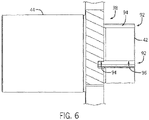
- the plurality of cutting grooves 92 each define a substantially rectangular recess formed in the cutting insert 28, as shown in FIG. 6 . In other embodiments, the plurality of cutting grooves 92 may define another shape (e.g., arcuate, round, curved, triangular, etc.), as desired.
- the cutting extension 66 of the cutting plate 32 defines a substantially frustoconical shape that tapers from a proximal end 98 to a distal end 100.
- the distal end 100 of the cutting extensions 66 defines a generally concave shape.
- the cutting extension 66 includes a first cutting edge 102, a second cutting edge 1 04, and an extension groove 106.
- the first cutting edge 102 and the second cutting edge 104 are sharpened (e,g., tapered down to a point) to aid in cutting or engaging solid matter.
- the extension groove 106 is arranged on a back surface 108 of the cutting extensions 66 and defines an axial recess therein.
- the extension groove 106 extends radially along a substantially curved profile from a location on the first cutting edge 102 adjacent to the distal end 100 to a location on the second cutting edge 104 adjacent to the proximal end 98.
- the extension groove 106 defines an axial recess with a substantially rectangular shape formed in the back surface 108 of the cutting extensions 66, as shown in FIG. 9 .
- the extension groove 106 may define another shape (e.g., arcuate, round, curved, triangular, etc.), as desired.
- each of the cutting blades 36 acts as an extension of the respective vane 52 of the impeller 30.
- the forward first protrusion 42 of the cutting insert 28 is dimensioned to extend through the concave distal end 100 of the cutting extension 66.
- the drive section 12 is configured to rotate the impeller 30, and thereby the cutting insert 28, in a desired direction.
- the rotation of the impeller 30 creates a low pressure at the inlet 18 that draws a process fluid into the inlet 18. From the inlet 18, the process fluid is drawn into the internal cavity 24 of the housing 16 where rotation of the impeller 30 centrifugally furnishes the process fluid to the outlet 20 at an increased pressure.
- rotation of the impeller 30 rotates the cutting blades 36 of the cutting insert 28 past the cutting extension 66 of the cutting plate 32.
- the leading edges 86 of the cutting insert 28, which include the plurality of serrated teeth 90, rotate past the cutting extension 66 and over the extension groove 106 in a scissor-type cutting action to break up and engage solids in the incoming process fluid flow.
- the serrated teeth 90 may engage and break up string-like materials prior to entering the internal cavity 16.
- the illustrated cutting assembly 26 provides additional cutting, chopping, or engagement locations by rotation of the axial portions 96 of the cutting grooves 92 past the distal end 100 of the cutting extension 66, and by rotation of the radial portions 94 of the cutting grooves 92 past the extension groove 106 formed in the back surface 108 of the cutting extension 66.
- These additional cutting, chopping, and/or engagement locations interact with and may alleviate the influence of solids that can get stuck or trapped within the cutting assembly 26.
- the cutting plate 32 may be axially adjusted with respect to the impeller 30, and the cutting insert 28 fastened therein, by adjusting an axial depth the fastening elements 82 and/or the fastening elements 84, as described above. Since the cutting insert 28 is a separate, or discrete, component relative to the impeller 30, the impeller 30 may not need to be fabricated from a hardened material. Additionally, since the cutting insert 28 may negate the need for the impeller 30 to be fabricated from a hardened material, the impeller 30 may be trimmed or modified, as desired. Furthermore, if the cutting, chopping, or pumping performance of the chopper pump 10 deteriorates over time, the cutting insert 28 or the impeller 30 may be replaced independently as required, and as opposed to an entire impeller structure.
- FIGS. 13-16 illustrate a cutting assembly 200 of the pump 10 according to another embodiment of the present invention.
- the cutting assembly 200 is similar to the cutting assembly 26, except as described below or illustrated in FIGS. 13-16 . Similar features are identified using like reference numerals.
- the cutting assembly 200 further includes a shredder 202 and a cutter ring 204.
- the shredder 202 forms a generally T-shaped cutter including a pair of opposing shredder extensions 208.
- the shredder extensions 208 extend angularly outward from an annular shredder hub 210. That is, the shredder extensions 208 are angled with respect to a center axis defined by the shredder 202 and extend toward the cutter ring 204.
- a coupling member 212 is configured to be received through the shredder hub 210 and couple the shredder 202 to the drive shaft 22 and the impeller 30 for rotation therewith.
- the cutting insert 28 is positioned between the shredder 202 and the impeller 30.
- the cutter ring 204 is dimensioned to be received within the inlet 18 of the housing 16.
- An inner surface 214 of the cutter ring 204 includes a plurality of cutting recesses 216 arranged circumferentially around the inner surface 214.
- the plurality of cutting recesses 216 each define a generally U-shaped cutout on the inner surface 214 of the cutter ring 204.
- the cutter ring 204 When assembled, as shown in Fig. 14 , the cutter ring 204 partially protrudes from the inlet 18 of the housing 16. The cutter ring 204 is secured between the cutting plate 32 and the retainer plate 206, when the fastening elements 82 are fastened into the threaded ring apertures 80 of the housing 16.
- the ends 218 of the shredder extensions 208 are configured to rotate past the plurality of cutting recesses 216 as the shredder 202 rotates with the impeller 30.
- the annular shredder hub 210 of the shredder 202 includes a rearward protrusion 226 dimensioned to be received by the forward protrusion 42 of the cutting insert 28.
- the rearward protrusion 226 may be inserted into the forward first protrusion 42 of the cutting insert 28.
- the coupling member 212 can be inserted through the annular shredder hub 210, the insert central hub 38, and the central hub 56 of the impeller 30 and fastened to the drive shaft 22. With the coupling member 212 fastened to the drive shaft 22, the impeller 30, the cutting insert 28, and the shredder 202 are rotationally coupled to the drive shaft 22.
- the rearward protrusion 226 and/or the forward first protrusion 42 may be keyed to prevent rotationally slipping between the shredder 202 and the impeller 30/the cutting insert 28.
- the shredder extensions 208 include a first shredding surface 228, a second shredding surface 230, and a tip protrusion 232.
- the first shredding surface 228 defines a generally S-shaped profile and includes a convex portion 234 and a concave portion 236.
- the second shredding surface 230 defines a generally convex profile.
- the tip protrusions 232 form a generally triangular shaped extension protruding from a lower surface 238 of each shredder extension 208 adjacent to a distal tip end 240 thereof.
- the combination of the first shredding surfaces 228 and the second shredding surfaces 230 provide each shredder extension 208 with a generally frustoconical shape that tapers towards the lower surface 238. That is, a thickness of the shredder extensions 208 may decrease as it extends toward the lower surface 238.
- the cutting action between the cutting insert 28 and the cutting plate 32 for the cutting assembly 200 is similar to the operation of the cutting assembly 26, described above.
- the shredder 202 rotates with the drive shaft 22, which rotates the shredder extensions 208 within the cutter ring 204 past the plurality of cutting recesses 216.
- the rotation of the shredder extensions 208 within the cutter ring 204 can push debris away from the suction within the inlet 18 to attempt to prevent the inlet 18 from becoming completely blocked by debris.
- the frustoconical shape defined by the shredder extensions 208 helps improve performance of the pump 10 by increasing flow. That is, the frustoconical shape improves flow by enabling the shredder 202 to act as a stage where rotation of the shredder 202 results in pumping of the fluid prior to the fluid entering and/or passing through the inlet 18.
- FIGS. 17 and 18 illustrate a cutting assembly 300 of the pump 10 according to another embodiment of the present invention.
- the cutting assembly 300 is similar to the cutting assembly 26, except as described below or illustrated in FIGS. 17 and 18 . Similar features are identified using like reference numerals.
- the cutting plate 32 includes three cutting extensions 66 arranged circumferentially around the inner surface 68 in approximately 120 degree increments.
- the mounting surface 68 includes three threaded mounting apertures 76.
- the cutting assembly 300 may not include the retainer ring 85. Instead, the axial positon of the cutting plate 32 may be controlled via the interaction between the cutting plate 32 and a plurality of adjusting fastening elements 302 and a plurality of set fastening element 304.
- the housing 16 includes a plurality of adjusting apertures 306 and a plurality of set apertures 308.
- the plurality of adjusting apertures 306 and the plurality of set apertures 308 are alternatingly arranged circumferentially around the inlet 18 of the housing 16.
- the plurality of adjusting apertures 306 are dimensioned to receive one of the adjusting fastening elements 302, which may be in the form of a threaded bolt.
- the plurality of set apertures 308 are dimensioned to threadingly receive one of the set fastening elements 304, which may be in the form of a threaded bolt.
- the plurality of adjusting fastening elements 302 When assembled, the plurality of adjusting fastening elements 302 extend through a corresponding one of the adjusting apertures 306 and into a corresponding one of the plurality of threaded mounting apertures 76. This fastens the cutting plate 32 within the internal cavity 24 of the housing 16 adjacent to the inlet 18.
- the set fastening elements 304 are threaded through a corresponding one of the plurality of adjusting apertures 308 to engage the mounting surface 74 of the cutting plate 32. In this way, the set fastening elements 304 act as a standoff or spacer to control an axial distance between the cutting plate 32 and the cutting insert 28.
- the cutting plate 32 is axially adjustable by adjusting an axial depth of the plurality of set fastening elements 304 and subsequently adjusting the adjusting fastening elements 302 until the mounting surface 74 of the cutting plate 32 engages the plurality of set fastening elements 304.
Landscapes
- Engineering & Computer Science (AREA)
- Mechanical Engineering (AREA)
- General Engineering & Computer Science (AREA)
- Structures Of Non-Positive Displacement Pumps (AREA)
Description
- The present invention relates generally to a chopper pump for pumping fluids containing solid matter and, more specifically, to a cutting assembly for breaking up solid matter in the fluid being supplied to the chopper pump into smaller pieces.
- Chopper pumps are implemented when a fluid supply contains solid matter that needs to be pumped, or displaced. The fluid supply is provided to an inlet of the chopper pump where an impeller rotates adjacent to a cutting plate that may be hardened. Rotation of the impeller adjacent to the cutting plate engages the solid matter and displaces the fluid supply from the inlet to an outlet. Typically, chopper pumps include a hardened impeller to aid in cutting the solid matter and increase the durability of the impeller. However, hardening an impeller inhibits the ability of a user to trim (i.e.., remove material from) the impeller to customize pump performance and/or contour the ultimate form factor of the impeller. Additionally, solid matter can become stuck or lodged between the impeller and the cutting plate during operation of the chopper pump, which leads to clogging and/or reduced pump efficiency.
-
US2014/377055A1 describes a centrifugal pump with a cutter mechanism having a toothed cutter auger affixed to an impeller, and a toothed cutter stator affixed to the volute casing. The auger is a rotor cutter profiled radially to match the inlet geometry of the impeller vanes while extending along its central axis towards the pump suction. The auger is radially concentric to the impeller and includes vanes numbered to match the number of vanes on the impeller. The auger is affixed to the impeller, with a lockscrew threaded into a common pump shaft. The radial profile of the auger makes a continuous vane with the impeller, and prevents solids from hanging on the inlet vane tip or center void. - In light of at least the above shortcomings, a need exits for an improved cutting assembly for a chopper pump that aids in removing solid matter that can inhibit performance and enables the form factor of the chopper pump impeller to be contoured or modified, if desired, while maintaining, or improving, cutting performance.
- The aforementioned shortcomings can be overcome by providing a cutting assembly for a chopper pump having a cutting insert removably received within a recess in an impeller and arranged adjacent to a cutting plate. The cutting insert is a separate component from the impeller, which negates the desire for the entire impeller to be fabricated from a hardened material. The cutting assembly disclosed allows the discrete cutting insert to be fabricated from a hardened material enabling the impeller, which may not be hardened in certain situations, to be trimmed or modified, if desired. Additionally, the cutting plate includes one or more cutting plate grooves to aid in removing solid matter that could get stuck between the cutting blade insert and the cutting plate.
- Some embodiments of the invention provide a cutting assembly for a chopper pump. The cutting assembly includes a cutting insert having a cutting blade extending radially therefrom, and an impeller having a central hub, a plurality of vanes, and an insert surface. The insert surface defines an axial recess that is dimensioned to receive the cutting insert therein. The cutting assembly further includes a cutting plate having a plate hub with a cutting extension protruding radially inward therefrom. Rotation of the impeller rotates the cutting blade past the cutting extension.
- Some embodiments of the invention provide a chopper pump including a drive section having a drive shaft, and a housing coupled to the drive section and having an inlet, an outlet, and an internal cavity arranged between the inlet and the outlet. The chopper pump further includes an impeller received within the internal cavity and coupled to the drive shaft for rotation therewith. The impeller includes a recess formed therein. The chopper pump further includes a cutting insert received within the recess of the impeller and having a cutting blade, and a cutting plate coupled to the housing within the internal cavity. The cutting plate includes a cutting extension that extends radially inward. Rotation of the impeller rotates the cutting blade past the cutting extension.
-
-
FIG. 1 is a perspective view of a chopper pump according to one embodiment of the invention. -
FIG. 2 is a partial cross-sectional view of the chopper pump ofFIG. 1 taken along line 2-2. -
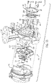
FIG. 3 is an exploded view of a cutting assembly and a housing of the chopper pump ofFIG. 1 . -
FIG. 4 is a back perspective view of a cutting insert of the chopper pump ofFIG. 1 . -
FIG. 5 is a front perspective view of the cutting insert of the chopper pump ofFIG. 1 . -
FIG. 6 is a cross-section view of the cutting insert ofFIG. 5 taken along line 6-6. -
FIG. 7 is a front view of a cutting plate of the chopper pump ofFIG. 1 . - FlG. 8 is a back view of the cutting plate of the chopper pump of
FIG. 1 . -
FIG. 9 is a cross-sectional view of the cutting plate ofFIG. 8 taken along line 9-9. -
FIG. 10 is a perspective view of the cutting plate and the impeller of the chopper pump ofFIG. 1 . -
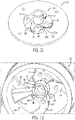
FIG. 11 is a back perspective view of the cutting insert inserted into the cutting plate of the chopper pump ofFIG. 1 . -
FIG. 12 is a front perspective view of the cutting insert inserted into the cutting plate of the chopper pump ofFIG. 1 . -
FIG. 13 is an exploded view of a cutting assembly and a housing of a chopper pump according to another embodiment of the invention. -
FIG. 14 is a partial cross-sectional view of the chopper pump and cutting assembly ofFIG. 13 . -
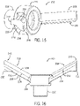
FIG. 15 is a perspective view of a shredder of the chopper pump and cutting assembly ofFIG. 13 . -
FIG. 16 is a side view of the shredder ofFIG. 15 . -
FIG. 17 is an exploded view of a cutting assembly and a housing of a chopper pump according to another embodiment of the invention. -
FIG. 18 is a partial cross-sectional view of the chopper pump and cutting assembly ofFIG. 17 . - Before any embodiments of the invention are explained in detail, it is to be understood that the invention is not limited in its application to the details of construction and the arrangement of components set forth in the following description or illustrated in the following drawings. The invention is capable of other embodiments and of being practiced or of being carried out in various ways. Also, it is to be understood that the phraseology and terminology used herein is for the purpose of description and should not be regarded as limiting. The use of "including," "comprising," or "having" and variations thereof herein is meant to encompass the items listed thereafter and equivalents thereof as well as additional items, Unless specified or limited otherwise, the terms "mounted," "connected," "supported,'" and "coupled" and variations thereof are used broadly and encompass both direct and indirect mountings, connections, supports, and couplings. Further, "connected" and "coupled" are not restricted to physical or mechanical connections or couplings.
- The following discussion is presented to enable a person skilled in the art to make and use embodiments of the invention. Various modifications to the illustrated embodiments will be readily apparent to those skilled in the art, and the generic principles herein can be applied to other embodiments and applications without departing from embodiments of the invention. Thus, embodiments of the invention are not intended to be limited to embodiments shown, but are to be accorded the widest scope consistent with the principles and features disclosed herein. The following detailed description is to be read with reference to the figures, in which like elements in different figures have like reference numerals. The figures, which are not necessarily to scale, depict selected embodiments and are not intended to limit the scope of embodiments of the invention. Skilled artisans will recognize the examples provided herein have many useful alternatives and fall within the scope of embodiments of the invention, as defined in the attached claims.
-
FIG. 1 illustrates achopper pump 10 according to one embodiment of the invention. Thechopper pump 10 includes adrive section 12 coupled to aninlet section 14. Theinlet section 14 includes ahousing 16 having aninlet 18 and anoutlet 20. In operation, thechopper pump 10 furnishes a process fluid from theinlet 18 of thehousing 16 to theoutlet 20 of thehousing 16, as will be described in detail below. - As shown in
FIG. 2 , thedrive section 12 includes adrive shaft 22 extending through thedrive section 12. Thedrive shaft 22 may extend through one or more bearings (not shown) and may be coupled to a driving mechanism (e.g., an electric motor or an internal combustion engine) that rotates thedrive shaft 22 in a desired direction for pumping of the supply fluid from theinlet 18 to theoutlet 20. - The
housing 16 defines aninternal cavity 24 in fluid communication with theinlet 18 and theoutlet 20. A cuttingassembly 26 is configured to be arranged within theinternal cavity 24 of thehousing 16. The cuttingassembly 26 includes a cuttinginsert 28, animpeller 30, and a cuttingplate 32. The cuttinginsert 28 is releasably coupled to theimpeller 30 and is arranged adjacent to the cuttingplate 32. The cuttinginsert 28 and theimpeller 30 are fastened to thedrive shaft 22 via animpeller fastening element 34 in the form of a threaded bolt. This enables theimpeller 30 and the cuttinginsert 28 to rotate with thedrive shaft 22 in a desired direction. - As shown in
FIG. 3 , the cuttinginsert 28 includes a plurality of cuttingblades 36 extending generally radially from and arranged circumferentially around an insertcentral hub 38. The plurality of cuttingblades 36 define a substantially curved shape and include a mountingaperture 40 extending therethrough. The mountingapertures 40 are arranged adjacent to the insertcentral hub 38. The cuttinginsert 28 is preferably fabricated from a hardened metal material (e.g., 440SST, PH grades of stainless, such as, 17-7PH, 17-5PH, and 15-5PH, as well as other hardenable steels). A hardness of the cuttingplate 28 can be greater (i.e., harder) than a hardness of theimpeller 30. The insertcentral hub 38 includes afirst protrusion 42 extending substantially perpendicularly from a proximal end of the plurality of cuttingblades 36 in a first direction, and asecond protrusion 44 extending substantially perpendicularly from the proximal end of the plurality of cuttingblades 36 in a second direction opposite the first direction. - The illustrated
impeller 30 is in the form of a semi-open impeller. In other embodiments, theimpeller 30 may be in the form of an open impeller or any other form capable of receiving a cutting insert. Theimpeller 30 includes ashroud 46 having afirst shroud surface 48 and an opposingsecond shroud surface 50. A plurality ofvanes 52 extend from and are arranged circumferentially around thefirst shroud surface 48 of theimpeller 30. The plurality ofvanes 52 define a substantially curved shape that curves from a shroudouter surface 54 of theshroud 46 toward acentral hub 56 of theimpeller 30. The curvature defined by the plurality ofvanes 52 is similar to the curvature defined by the plurality of cutting blades 36 (as shown inFIG. 10 ). In other embodiments, the plurality ofvanes 52 may define an alternative shape, for example a substantially straight, or linear, shape between the shroudouter surface 54 and thecentral hub 56. The illustratedimpeller 30 includes fourvanes 52. In other embodiments, theimpeller 30 may include more or less than fourvanes 52. - The
central hub 56 of theimpeller 30 includes arecess 58 defined by aninsert surface 60 that is axially recessed and dimensioned to receive the cuttinginsert 28. Therecess 58 is dimensioned to accommodate the cuttinginsert 28 therein. Theinsert surface 60 extends from thecentral hub 56 partially along each of the plurality ofvanes 52. That is, each of the plurality ofvanes 52 defines a step change in an axial dimension at a location between the shroudouter surface 54 and thecentral hub 56. The location at which the step change in axial dimension occurs in each of the plurality ofvanes 52 is congruent with a distance that the plurality of cuttingblades 36 radially extend from the insertcentral hub 38 of the cuttinginsert 28. Additionally, an axial depth of the recess 58 (i.e., the magnitude of the step change in axial dimension of the plurality of vanes 52) is congruent with a thickness of the plurality of cuttingblades 36. In this way, when the cuttinginsert 28 is inserted into therecess 58 of the impeller 30 (as shown inFIG. 10 ), the plurality of cuttingblades 36 are arranged flush with the plurality ofvanes 52. - With continued reference to
FIG. 3 , theinsert surface 60 includes a plurality ofinsert apertures 62 recessed into theinsert surface 60 and arranged circumferentially around acentral hub aperture 64 of thecentral hub 56. The plurality ofinsert apertures 62 are each dimensioned to threadably received afastening element 65, which may be in the form of an flathead cap screw or bolt. The plurality ofinsert apertures 62 are arranged to align with the mountingapertures 40 of the cuttinginsert 28. During assembly and operation, theinsert apertures 62 are configured to align with the mountingapertures 40 to enable thefastening elements 65 to extend through the mountingapertures 40 and thread into theinsert apertures 62. This properly locates the cuttinginsert 28 within therecess 58 and rotationally secures the cuttinginsert 28 and the impeller 30 (i.e., prevent the cuttinginsert 28 from slipping, or becoming rotationally offset, with respect to the impeller 30). Thecentral hub aperture 64 is dimensioned to receive the backwardsecond protrusion 44 of the insertcentral hub 38. - The cutting
plate 32 includes a cuttingextension 66 protruding radially inward from aninner surface 68 of aplate hub 70. The illustratedcutting plate 32 includes one cuttingextension 66 arranged on theinner surface 68 of theplate hub 70. In other embodiments, the cuttingplate 32 may include more than one cuttingextensions 66 arranged circumferentially around theinner surface 68. For example, in one embodiment, the cuttingplate 32 may include two cuttingextensions 66 arranged circumferentially in approximately 180 degree increments on theinner surface 68. In another embodiment, the cuttingplate 32 may include three cuttingextensions 66 arranged circumferentially in approximately 120 degree increments on theinner surface 68. - The
inner surface 68 of theplate hub 70 defines an opening with a diameter that is substantially equal to a diameter of theinlet 18 of thehousing 16. Theplate hub 70 extends substantially perpendicularly from abase 72 of the cuttingplate 32. Thebase 72 of the cuttingplate 32 includes a mountingsurface 74 having a plurality of threaded mountingapertures 76 arranged circumferentially around and extending through the mountingsurface 74. - The
housing 16 includes aninlet face 77 having a plurality ofplate apertures 78 and a plurality of threadedring apertures 80 arranged thereon. The plurality ofplate apertures 78 and the plurality of threadedring apertures 80 are alternatingly arranged circumferentially around theinlet face 77 of thehousing 16. The plurality ofplate apertures 78 extend axially through aninlet wall 81 of thehousing 16, which circumscribes theinlet 18. The plurality ofplate apertures 78 are dimensioned to receive afastening element 84 in the form of a threaded bolt. The plurality ofring apertures 80 extend partially through theinlet wall 81 and are arranged radially inward compared to the plurality ofplate apertures 78. The plurality ofring apertures 80 are dimensioned to receive afastening element 82 in the form of a threaded bolt. - When assembled (as shown in
FIGS. 1 and2 ), each of thefastening elements 84 is inserted into and through a corresponding one of the plurality ofplate apertures 78 and threaded into a corresponding one of the plurality of threaded mountingapertures 76 on the mountingsurface 74 of the cuttingplate 32. This fastens the cuttingplate 32 within theinternal cavity 24 of thehousing 16 adjacent to theinlet 18. Each of the plurality offastening elements 82 is threaded into a corresponding one of the plurality of threadedring apertures 80 to secure aretainer ring 85 in engagement with a distal end of theplate hub 70, which may extend partially out of theinlet 18. Theretainer ring 85 defines a generally annular shape and includes a plurality ofretainer apertures 87 arranged circumferentially thereon. Theretainer apertures 87 are arranged to align with thering apertures 80, when assembled. - The relative threaded interaction between the
fastening elements 84 secured to the cuttingplate 32 and thefastening elements 82 securing theretainer ring 85 enables the axial relation between the cuttingplate 32 and the cuttinginsert 28 to be selectively controlled. That is, the cuttingplate 32 is axially adjustable by adjusting an axial depth that thefastening elements 84 are threaded into the plurality of threaded mountingapertures 76 and/or by adjusting an axial distance between theinlet face 77 and theretainer ring 85, which is set by thefastening elements 82. In one implementation, the axial relation between the cuttingplate 32 and the cuttinginsert 28 may be set by the axial depth thefastening elements 84 are threaded into the threaded mountingapertures 76, and theretainer ring 85 may be utilized to secure the cuttingplate 32 in place via thefastening elements 82. In another implementation, the axial relation between the cutting plate and the cuttinginsert 28 may be set by the axial distance between theretainer ring 85 and theinlet face 77, which is controlled via thefastening elements 82, and thefastening elements 84 may be utilized to secure the cuttingplate 32 in place. - As shown in
FIGS. 4 and 5 , the plurality of cuttingblades 36 include aleading edge 86 and a trailingedge 88. The leadingedges 86 include a plurality ofserrated teeth 90 arranged therealong to aid in cutting or engaging solid matter, as will be described below. The cuttinginsert 28 includes a plurality of cuttinggrooves 92 arranged circumferentially thereon. The plurality of cuttinggrooves 92 include aradial section 94 and anaxial section 96 arranged substantially perpendicularly to theradial section 94. Theradial sections 94 are axially recessed into the cuttinginsert 28 and each extend radially along a substantially curved profile from aproximal end 97 of a corresponding one of theleading edges 86 to the forwardfirst protrusion 42. Theaxial sections 96 are radially recessed into the forwardfirst protrusion 42 and extend axially along the length of the forwardfirst protrusion 42 in a substantially linear profile. The plurality of cuttinggrooves 92 each define a substantially rectangular recess formed in the cuttinginsert 28, as shown inFIG. 6 . In other embodiments, the plurality of cuttinggrooves 92 may define another shape (e.g., arcuate, round, curved, triangular, etc.), as desired. - As shown in
FIGS. 7 and 8 , the cuttingextension 66 of the cuttingplate 32 defines a substantially frustoconical shape that tapers from aproximal end 98 to adistal end 100. Thedistal end 100 of the cuttingextensions 66 defines a generally concave shape. The cuttingextension 66 includes afirst cutting edge 102, a second cutting edge 1 04, and anextension groove 106. Thefirst cutting edge 102 and thesecond cutting edge 104 are sharpened (e,g., tapered down to a point) to aid in cutting or engaging solid matter. Theextension groove 106 is arranged on aback surface 108 of the cuttingextensions 66 and defines an axial recess therein. Theextension groove 106 extends radially along a substantially curved profile from a location on thefirst cutting edge 102 adjacent to thedistal end 100 to a location on thesecond cutting edge 104 adjacent to theproximal end 98. Theextension groove 106 defines an axial recess with a substantially rectangular shape formed in theback surface 108 of the cuttingextensions 66, as shown inFIG. 9 . In other embodiments, theextension groove 106 may define another shape (e.g., arcuate, round, curved, triangular, etc.), as desired. - When the cutting
assembly 26 is assembled as shown inFIGS. 10-12 , the cuttinginsert 28 is fastened within therecess 58 of theimpeller 30 for rotation therewith. With the cuttinginsert 28 fastened within therecess 58, each of thecutting blades 36 acts as an extension of therespective vane 52 of theimpeller 30. The forwardfirst protrusion 42 of the cuttinginsert 28 is dimensioned to extend through the concavedistal end 100 of the cuttingextension 66. - During operation of the
chopper pump 10, thedrive section 12 is configured to rotate theimpeller 30, and thereby the cuttinginsert 28, in a desired direction. The rotation of theimpeller 30 creates a low pressure at theinlet 18 that draws a process fluid into theinlet 18. From theinlet 18, the process fluid is drawn into theinternal cavity 24 of thehousing 16 where rotation of theimpeller 30 centrifugally furnishes the process fluid to theoutlet 20 at an increased pressure. - While the process fluid is passing from the
inlet 18 to theoutlet 20 during operation of thechopper pump 10, the process fluid flows through the cuttingassembly 26. In particular, rotation of theimpeller 30 rotates thecutting blades 36 of the cuttinginsert 28 past the cuttingextension 66 of the cuttingplate 32. The leadingedges 86 of the cuttinginsert 28, which include the plurality ofserrated teeth 90, rotate past the cuttingextension 66 and over theextension groove 106 in a scissor-type cutting action to break up and engage solids in the incoming process fluid flow. Additionally, theserrated teeth 90 may engage and break up string-like materials prior to entering theinternal cavity 16. Further, theaxial portions 96 of the cuttinggrooves 92 rotate past the distal ends 100 of the cuttingextension 66, and theradial portions 94 of the cuttinggrooves 92 rotate past theextension groove 106 formed in theback surface 108 of the cuttingextension 66. Thus, the illustrated cuttingassembly 26 provides additional cutting, chopping, or engagement locations by rotation of theaxial portions 96 of the cuttinggrooves 92 past thedistal end 100 of the cuttingextension 66, and by rotation of theradial portions 94 of the cuttinggrooves 92 past theextension groove 106 formed in theback surface 108 of the cuttingextension 66. These additional cutting, chopping, and/or engagement locations interact with and may alleviate the influence of solids that can get stuck or trapped within the cuttingassembly 26. - Once the
chopper pump 10 is powered down, the cuttingplate 32 may be axially adjusted with respect to theimpeller 30, and the cuttinginsert 28 fastened therein, by adjusting an axial depth thefastening elements 82 and/or thefastening elements 84, as described above. Since the cuttinginsert 28 is a separate, or discrete, component relative to theimpeller 30, theimpeller 30 may not need to be fabricated from a hardened material. Additionally, since the cuttinginsert 28 may negate the need for theimpeller 30 to be fabricated from a hardened material, theimpeller 30 may be trimmed or modified, as desired. Furthermore, if the cutting, chopping, or pumping performance of thechopper pump 10 deteriorates over time, the cuttinginsert 28 or theimpeller 30 may be replaced independently as required, and as opposed to an entire impeller structure. -
FIGS. 13-16 illustrate a cuttingassembly 200 of thepump 10 according to another embodiment of the present invention. The cuttingassembly 200 is similar to the cuttingassembly 26, except as described below or illustrated inFIGS. 13-16 . Similar features are identified using like reference numerals. As shown inFIGS. 13 and14 , the cuttingassembly 200 further includes ashredder 202 and acutter ring 204. Theshredder 202 forms a generally T-shaped cutter including a pair of opposingshredder extensions 208. Theshredder extensions 208 extend angularly outward from anannular shredder hub 210. That is, theshredder extensions 208 are angled with respect to a center axis defined by theshredder 202 and extend toward thecutter ring 204. - A
coupling member 212 is configured to be received through theshredder hub 210 and couple theshredder 202 to thedrive shaft 22 and theimpeller 30 for rotation therewith. When assembled, the cuttinginsert 28 is positioned between theshredder 202 and theimpeller 30. Thecutter ring 204 is dimensioned to be received within theinlet 18 of thehousing 16. Aninner surface 214 of thecutter ring 204 includes a plurality of cuttingrecesses 216 arranged circumferentially around theinner surface 214. The plurality of cuttingrecesses 216 each define a generally U-shaped cutout on theinner surface 214 of thecutter ring 204. - When assembled, as shown in
Fig. 14 , thecutter ring 204 partially protrudes from theinlet 18 of thehousing 16. Thecutter ring 204 is secured between the cuttingplate 32 and theretainer plate 206, when thefastening elements 82 are fastened into the threadedring apertures 80 of thehousing 16. The ends 218 of theshredder extensions 208 are configured to rotate past the plurality of cuttingrecesses 216 as theshredder 202 rotates with theimpeller 30. - With reference to
FIGS. 15 and 16 , theannular shredder hub 210 of theshredder 202 includes arearward protrusion 226 dimensioned to be received by theforward protrusion 42 of the cuttinginsert 28. To assemble theshredder 202 and the cuttinginsert 28, therearward protrusion 226 may be inserted into the forwardfirst protrusion 42 of the cuttinginsert 28. Then, thecoupling member 212 can be inserted through theannular shredder hub 210, the insertcentral hub 38, and thecentral hub 56 of theimpeller 30 and fastened to thedrive shaft 22. With thecoupling member 212 fastened to thedrive shaft 22, theimpeller 30, the cuttinginsert 28, and theshredder 202 are rotationally coupled to thedrive shaft 22. In one embodiment, therearward protrusion 226 and/or the forwardfirst protrusion 42 may be keyed to prevent rotationally slipping between theshredder 202 and theimpeller 30/the cuttinginsert 28. - The
shredder extensions 208 include afirst shredding surface 228, asecond shredding surface 230, and atip protrusion 232. Thefirst shredding surface 228 defines a generally S-shaped profile and includes aconvex portion 234 and aconcave portion 236. Thesecond shredding surface 230 defines a generally convex profile. The tip protrusions 232 form a generally triangular shaped extension protruding from alower surface 238 of eachshredder extension 208 adjacent to adistal tip end 240 thereof. The combination of the first shredding surfaces 228 and the second shredding surfaces 230 provide eachshredder extension 208 with a generally frustoconical shape that tapers towards thelower surface 238. That is, a thickness of theshredder extensions 208 may decrease as it extends toward thelower surface 238. - In operation, the cutting action between the cutting
insert 28 and the cuttingplate 32 for the cuttingassembly 200 is similar to the operation of the cuttingassembly 26, described above. In addition, theshredder 202 rotates with thedrive shaft 22, which rotates theshredder extensions 208 within thecutter ring 204 past the plurality of cutting recesses 216. The rotation of theshredder extensions 208 within thecutter ring 204 can push debris away from the suction within theinlet 18 to attempt to prevent theinlet 18 from becoming completely blocked by debris. Also, the frustoconical shape defined by theshredder extensions 208 helps improve performance of thepump 10 by increasing flow. That is, the frustoconical shape improves flow by enabling theshredder 202 to act as a stage where rotation of theshredder 202 results in pumping of the fluid prior to the fluid entering and/or passing through theinlet 18. -
FIGS. 17 and18 illustrate a cuttingassembly 300 of thepump 10 according to another embodiment of the present invention. The cuttingassembly 300 is similar to the cuttingassembly 26, except as described below or illustrated inFIGS. 17 and18 . Similar features are identified using like reference numerals. As shown inFIGS. 17 and18 , the cuttingplate 32 includes three cuttingextensions 66 arranged circumferentially around theinner surface 68 in approximately 120 degree increments. The mountingsurface 68 includes three threaded mountingapertures 76. In the illustrated example, the cuttingassembly 300 may not include theretainer ring 85. Instead, the axial positon of the cuttingplate 32 may be controlled via the interaction between the cuttingplate 32 and a plurality of adjustingfastening elements 302 and a plurality ofset fastening element 304. - The
housing 16 includes a plurality of adjustingapertures 306 and a plurality ofset apertures 308. The plurality of adjustingapertures 306 and the plurality of setapertures 308 are alternatingly arranged circumferentially around theinlet 18 of thehousing 16. The plurality of adjustingapertures 306 are dimensioned to receive one of the adjustingfastening elements 302, which may be in the form of a threaded bolt. The plurality of setapertures 308 are dimensioned to threadingly receive one of the setfastening elements 304, which may be in the form of a threaded bolt. - When assembled, the plurality of adjusting
fastening elements 302 extend through a corresponding one of the adjustingapertures 306 and into a corresponding one of the plurality of threaded mountingapertures 76. This fastens the cuttingplate 32 within theinternal cavity 24 of thehousing 16 adjacent to theinlet 18. The setfastening elements 304 are threaded through a corresponding one of the plurality of adjustingapertures 308 to engage the mountingsurface 74 of the cuttingplate 32. In this way, theset fastening elements 304 act as a standoff or spacer to control an axial distance between the cuttingplate 32 and the cuttinginsert 28. That is, the cuttingplate 32 is axially adjustable by adjusting an axial depth of the plurality of setfastening elements 304 and subsequently adjusting the adjustingfastening elements 302 until the mountingsurface 74 of the cuttingplate 32 engages the plurality of setfastening elements 304. - It will be appreciated by those skilled in the art that while the invention has been described above in connection with particular embodiments and examples, the invention is not necessarily so limited, and that numerous other embodiments, examples, uses, modifications and departures from the embodiments, examples and uses are intended to be encompassed by the claims attached hereto.
- Various features and advantages of the invention are set forth in the following claims.
Claims (15)
- A cutting assembly (26) for a chopper pump (10), the cutting assembly (26) comprising:a cutting insert (28) including a cutting blade (36) extending radially therefrom and having a cutting blade thickness;an impeller (30) including a central hub (56), a plurality of vanes (52), and an insert surface (60) , wherein the insert surface (60) defines an axial recess (58) having an axial depth that is congruent with the cutting blade thickness and is dimensioned to receive the cutting insert (28) therein; anda cutting plate (32) including a plate hub (70) having a cutting extension (66) protruding radially inward therefrom,wherein rotation of the impeller (30) rotates the cutting blade (36) past the cutting extension (66).
- The cutting assembly (26) of claim 1, wherein the cutting insert (28) includes a plurality of cutting blades (36) extending radially from an insert central hub (38).
- The cutting assembly (26) of claim 2, wherein the plurality of cutting blades (36) define a substantially curved shape or wherein the plurality of cutting blades (36) each include a leading edge (86) having a plurality of serrated teeth (90) arranged therealong.
- The cutting assembly (26) of claim 1, claim 2 or claim 3, wherein the insert surface (60) includes a plurality of insert apertures (62) recessed therein and arranged circumferentially around the central hub (56), and wherein the plurality of insert apertures (62) are arranged to align with a corresponding plurality of mounting apertures (40) on the cutting insert (28) and, optionally or preferably, wherein the plurality of insert apertures (62) and the plurality of mounting apertures (40) are configured to receive a fastening element (65) to rotationally secure the cutting insert (28) to the impeller (30).
- The cutting assembly (26) of claim 1 or of any of claims 2 to 4, wherein the cutting insert (28) includes a cutting groove (92) arranged thereon that defines a recess having a radial section (94) and an axial section (96).
- The cutting assembly (26) of claim 5, wherein the radial section (94) is axially recessed into the cutting insert (28) and extends radially along a substantially curved profile or wherein the axial section (96) is radially recessed into a protrusion (42) of the cutting insert (28) and extends axially along the length of the protrusion (42) in a substantially linear profile.
- The cutting assembly (26) of claim 1 or of any of claims 2 to 6, wherein the cutting extension (66) defines a substantially frustoconical shape.
- The cutting assembly (26) of claim 1 or of any of claims 2 to 7, wherein the cutting extension (66) includes, a first cutting edge (102), a second cutting edge (104), a proximal end (98), and a distal end (100).
- The cutting assembly (26) of claim 8, wherein the distal end (100) defines a generally concave shape
- The cutting assembly (26) of claim 8 or 9, wherein the cutting extension (66) includes an extension groove (106) axially recessed therein and, optionally or preferably wherein the extension groove (106) extends radially along a substantially curved profile from a location on the first cutting edge (102) adjacent to the distal end (100) to a location on the second cutting edge (104) adjacent to the proximal end (98).
- A chopper pump (10) comprising:a drive section (12) including a drive shaft (22);a housing (16) coupled to the drive section (12) and including an inlet (18), an outlet (20), and an internal cavity (24) arranged between the inlet (18) and the outlet (20);an impeller (30) received within the internal cavity (24) and coupled to the drive shaft (22) for rotation therewith, the impeller (30) including an external impeller surface and a recess (58) formed therein;a cutting insert (28) received within the recess (58) of the impeller (30) and including a cutting blade (36) having an external blade surface;wherein the external impeller surface and the external blade surface are substantially flush with one another; anda cutting plate (32) coupled to the housing (16) within the internal cavity (24), the cutting plate (32) including a cutting extension (66) that extends radially inward,wherein rotation of the impeller (30) rotates the cutting blade (36) past the cutting extension (66).
- The chopper pump (10) of claim 11, wherein a leading edge (86) of the cutting blade (36) includes a plurality of serrated teeth (90) arranged therealong.
- The chopper pump (10) of claim 11 or claim 12, wherein the cutting insert (28) includes a cutting groove (92) arranged thereon that defines a recess having a radial section (94) and an axial section (96).
- The chopper pump (10) of claim 11, claim 12 or claim 13, wherein the cutting extension (66) includes an extension groove (106) axially recessed therein and, optionally or preferably, wherein the extension groove (106) extends radially along a substantially curved profile from a location on a first cutting edge (102) adjacent to a distal end (100) of the cutting extension (66) to a location on a second cutting edge (104) adjacent to a proximal end (98) of the cutting extension (66).
- The chopper pump (10) of any of claims 11 to 14, wherein the cutting plate (32) is axially adjustable with respect to the impeller (30).
Applications Claiming Priority (2)
| Application Number | Priority Date | Filing Date | Title |
|---|---|---|---|
| US201662327810P | 2016-04-26 | 2016-04-26 | |
| PCT/US2017/029664 WO2017189741A1 (en) | 2016-04-26 | 2017-04-26 | Cutting assembly for a chopper pump |
Publications (3)
| Publication Number | Publication Date |
|---|---|
| EP3449130A1 EP3449130A1 (en) | 2019-03-06 |
| EP3449130A4 EP3449130A4 (en) | 2020-01-22 |
| EP3449130B1 true EP3449130B1 (en) | 2022-11-09 |
Family
ID=60088971
Family Applications (1)
| Application Number | Title | Priority Date | Filing Date |
|---|---|---|---|
| EP17790355.6A Active EP3449130B1 (en) | 2016-04-26 | 2017-04-26 | Cutting assembly for a chopper pump |
Country Status (3)
| Country | Link |
|---|---|
| US (3) | US10533557B2 (en) |
| EP (1) | EP3449130B1 (en) |
| WO (1) | WO2017189741A1 (en) |
Families Citing this family (17)
| Publication number | Priority date | Publication date | Assignee | Title |
|---|---|---|---|---|
| WO2014145910A1 (en) | 2013-03-15 | 2014-09-18 | Pentair Pump Group, Inc. | Cutting blade assembly |
| EP3449130B1 (en) | 2016-04-26 | 2022-11-09 | Pentair Flow Technologies, LLC | Cutting assembly for a chopper pump |
| PL3312426T3 (en) * | 2016-10-18 | 2019-12-31 | Xylem Europe Gmbh | Cutter wheel, cutter disc as well as cutter assembly suitable for grinder pumps |
| US10473103B2 (en) * | 2017-03-13 | 2019-11-12 | Vaughan Company, Inc. | Chopper pump with double-edged cutting bars |
| CN108799181A (en) * | 2018-06-08 | 2018-11-13 | 安徽阿莫斯泵业有限公司 | A kind of sewage pump inlet saw-blade type cutter device |
| US11161121B2 (en) | 2019-05-10 | 2021-11-02 | Jung Pumpen Gmbh | Cutting blade assembly |
| CN110425146A (en) * | 2019-07-15 | 2019-11-08 | 河北通达泵阀集团有限公司 | A kind of high-lift multi-stage Pulp pump |
| EP3988794B1 (en) * | 2020-10-26 | 2024-07-31 | Xylem Europe GmbH | Impeller seat with a guide pin for a pump |
| US11512701B2 (en) * | 2020-11-10 | 2022-11-29 | Chengli Li | Cutting system for a grinding pump and related grinding pump |
| US12016496B2 (en) | 2020-12-31 | 2024-06-25 | Sharkninja Operating Llc | Micro puree machine |
| US12064056B2 (en) | 2020-12-31 | 2024-08-20 | Sharkninja (Hong Kong) Company Limited | Micro puree machine |
| US12016493B2 (en) | 2020-12-31 | 2024-06-25 | Sharkninja Operating Llc | Micro puree machine |
| USD983603S1 (en) | 2020-12-31 | 2023-04-18 | Sharkninja Operating Llc | Blade for a micro puree machine |
| US11925298B2 (en) | 2020-12-31 | 2024-03-12 | Sharkninja Operating Llc | Micro puree machine |
| US11871765B2 (en) | 2020-12-31 | 2024-01-16 | Sharkninja Operating Llc | Micro puree machine |
| USD990239S1 (en) * | 2021-12-17 | 2023-06-27 | Daito Giken, Inc. | Cutter blade for coffee grinders |
| WO2024058737A1 (en) * | 2022-09-15 | 2024-03-21 | Eys Metal Sanayi Ve Ticaret Limited Sirketi | A novel impeller design for submersible centrifugal wastewater pumps |
Family Cites Families (136)
| Publication number | Priority date | Publication date | Assignee | Title |
|---|---|---|---|---|
| US1148547A (en) | 1914-11-13 | 1915-08-03 | Josiah Anstice | Potato-masher. |
| US1355982A (en) * | 1918-03-11 | 1920-10-19 | Bour Harry E La | Centrifugal pump |
| US1713037A (en) | 1927-11-08 | 1929-05-14 | Harry E Ellis | Cutter head for pumps |
| US2014019A (en) | 1935-06-03 | 1935-09-10 | Girl Christian | Attachment for coupes |
| US2103896A (en) | 1935-12-12 | 1937-12-28 | Sturtevant Mill Co | Machine for disintegrating, screening, and pumping fibrous or paper making stocks |
| US2265758A (en) | 1940-05-29 | 1941-12-09 | Buffalo Pumps Inc | Pump |
| US2259623A (en) | 1940-10-14 | 1941-10-21 | Charles W Dieckmann | Rotary cutter |
| US2262039A (en) | 1940-11-01 | 1941-11-11 | Richard B Pekor | Centrifugal pump impeller |
| GB584395A (en) | 1942-12-30 | 1947-01-14 | Sulzer Ag | Improvements in or relating to pumps for dealing with liquids containing solid substances |
| US2420420A (en) | 1943-10-07 | 1947-05-13 | Company The Northern Trust | Self-priming centrifugal pump |
| NL71622C (en) | 1946-03-30 | |||
| US2672075A (en) | 1949-03-23 | 1954-03-16 | Fraser Douglas | Machine for treating paper mill waste |
| US3109714A (en) | 1959-07-22 | 1963-11-05 | Technicon Instr | Means for separating fluids from each other |
| US3073535A (en) | 1960-03-24 | 1963-01-15 | Black Clawson Co | Paper machinery |
| US3128051A (en) | 1960-11-07 | 1964-04-07 | Dag Mfg Co | Pump |
| US3096718A (en) | 1961-12-12 | 1963-07-09 | Conard Kenner | Trash cutter for a pump |
| US3155046A (en) | 1962-04-23 | 1964-11-03 | Vaughan Co | Centrifugal nonclogging pump |
| US3155330A (en) | 1963-02-11 | 1964-11-03 | Holz Otto | Cutting device for manure pumps |
| US3169486A (en) | 1963-07-29 | 1965-02-16 | Duriron Co | Pumps |
| US3325107A (en) | 1964-01-16 | 1967-06-13 | Ultra Inc | Disintegrator pump |
| US3323650A (en) | 1964-12-04 | 1967-06-06 | Jr James A Kilbane | Marine chlorinator |
| US3380669A (en) | 1966-04-11 | 1968-04-30 | Black Clawson Co | Plural defibering zones in a pulping apparatus |
| US3380673A (en) | 1966-05-12 | 1968-04-30 | Itt | Pump apparatus |
| US3444818A (en) | 1966-10-10 | 1969-05-20 | Robert W Sutton | Centrifugal pump |
| DE1528694A1 (en) | 1966-10-12 | 1969-05-22 | Eisele Soehne Franz | Centrifugal liquid manure pump with a knife disc arranged in the inlet of the suction nozzle in the pump housing |
| US3447475A (en) | 1967-01-09 | 1969-06-03 | Albert Blum | Centrifugal pump |
| US3560106A (en) | 1969-02-13 | 1971-02-02 | Nils Johan Sahlstrom | Slurry handling pump |
| USRE28677E (en) | 1969-09-29 | 1976-01-13 | Black Clawson Fibreclaim, Inc. | Waste treatment system |
| US3658262A (en) | 1970-10-23 | 1972-04-25 | Sterling Drug Inc | Sewage sludge and garbage grinder |
| US3692422A (en) | 1971-01-18 | 1972-09-19 | Pierre Mengin Ets | Shearing pump |
| US3650481A (en) | 1971-04-01 | 1972-03-21 | Hydr O Matic Pump Co | Grinder pump |
| US3738581A (en) | 1971-10-12 | 1973-06-12 | Oberdorfer Foundries Inc | Macerating pump with means for preventing blockages |
| US3843063A (en) | 1973-02-06 | 1974-10-22 | Morden Machines Co | Shredding and defiberizing machine |
| DE2452548A1 (en) | 1973-11-19 | 1975-05-22 | Sneek Landustrie | CENTRIFUGAL PUMP |
| US3889885A (en) | 1974-01-11 | 1975-06-17 | Black Clawson Co | Pulping apparatus |
| US3915394A (en) | 1974-03-21 | 1975-10-28 | Bendix Corp | Centrifugal pump including contamination chopping means |
| US3973866A (en) | 1975-01-02 | 1976-08-10 | Vaughan Co., Inc. | Centrifugal chopping slurry pump |
| US4074869A (en) | 1977-03-11 | 1978-02-21 | Johnson Walter G | Machine for shredding leaves and garden debris |
| US4108386A (en) | 1977-04-13 | 1978-08-22 | Mcneil Corporation | Grinder pump |
| US4141510A (en) | 1977-06-15 | 1979-02-27 | Arthur Smith | Material reduction means for pumps |
| US4109872A (en) | 1977-07-29 | 1978-08-29 | The Black Clawson Company | Pulping apparatus for liquid slurry stock |
| US4145008A (en) | 1977-08-22 | 1979-03-20 | The Gorman-Rupp Company | Waste material pumping apparatus |
| DE3015755A1 (en) | 1980-04-24 | 1981-11-05 | Albert 5204 Lohmar Blum | Submersible vertical pump for sewage - has wedges on baseplate to allow easy adjustment of gap between baseplate and impeller |
| US4378093A (en) | 1980-12-11 | 1983-03-29 | Keener Steven M | Grinder pump cutter assembly |
| US4842479A (en) | 1981-01-29 | 1989-06-27 | Vaughan Co., Inc. | High head centrifugal slicing slurry pump |
| US5076757A (en) | 1981-01-29 | 1991-12-31 | Vaughan Co., Inc. | High head centrifugal slicing slurry pump |
| US4456424A (en) | 1981-03-05 | 1984-06-26 | Toyo Denki Kogyosho Co., Ltd. | Underwater sand pump |
| US4402648A (en) | 1981-08-31 | 1983-09-06 | A. O. Smith Harvestore Products, Inc. | Chopper pump |
| US4480796A (en) | 1982-01-25 | 1984-11-06 | Beloit Corporation | Pulping apparatus including improved rotor |
| JPS5966361A (en) | 1982-10-04 | 1984-04-14 | 栄船舶電機株式会社 | Disposer |
| SE444969B (en) | 1982-10-11 | 1986-05-20 | Flygt Ab | Centrifugal pump intended for pumping of liquids containing solid particles |
| US4778336A (en) | 1987-07-09 | 1988-10-18 | Weil Pump Company | Cutter pump subassembly |
| JPH0752394Y2 (en) | 1988-03-25 | 1995-11-29 | 株式会社荏原製作所 | Grinder pump |
| US4904159A (en) | 1988-07-18 | 1990-02-27 | Suburbia Systems, Inc. | Pump impeller |
| SE466766B (en) | 1989-04-27 | 1992-03-30 | Flygt Ab Itt | Centrifugal pump intended for pumping of liquids containing solid particles, for example, rags and other long-stretched objects |
| IT1234125B (en) | 1989-07-05 | 1992-04-29 | Nowax Srl | PALLET IMPELLER OPEN PARTICULARLY FOR CENTRIFUGAL PUMP |
| US5016825A (en) | 1990-02-14 | 1991-05-21 | Mcneil (Ohio) Corporation | Grinding impeller assembly for a grinder pump |
| US5213469A (en) | 1992-01-10 | 1993-05-25 | General Signal Corporation | Sewage pump with improved inlet construction |
| US5456580A (en) | 1992-05-26 | 1995-10-10 | Vaughan Co., Inc. | Multistage centrifugal chopper pump |
| US5460482A (en) | 1992-05-26 | 1995-10-24 | Vaughan Co., Inc. | Centrifugal chopper pump with internal cutter |
| US5256032A (en) | 1992-05-26 | 1993-10-26 | Vaugan Co., Inc. | Centrifugal chopper pump |
| US5265990A (en) | 1992-12-23 | 1993-11-30 | Kurt Manufacturing Company, Inc. | Short toolholder system |
| US5531385A (en) | 1993-05-07 | 1996-07-02 | Witsken; Anthony | Apparatus and methods for wet grinding |
| DE4319616A1 (en) | 1993-06-14 | 1994-12-15 | Wilo Gmbh | Submersible motor-driven pump |
| US5346143A (en) | 1993-07-14 | 1994-09-13 | Crisafulli Pump Company, Inc. | Fish mincer pump |
| US5906435A (en) | 1993-09-13 | 1999-05-25 | Continental Products Corporation | Particulate drum mixer with scoop section and seal assembly with bladder |
| US5707016A (en) | 1996-07-01 | 1998-01-13 | Witsken; Anthony | Apparatus and methods for wet grinding |
| DK172958B1 (en) | 1997-06-12 | 1999-10-18 | Wolfking Danmark As | Arrangement for attaching a replaceable cutting blade to a rotary knife holder in a cutting kit for a meat chopper. |
| US5918822A (en) | 1998-01-26 | 1999-07-06 | Sternby; Arthur J. | Channeled pulp rotor |
| DE19834815A1 (en) | 1998-08-01 | 2000-02-10 | Orpu Gmbh | Pump with cutting device for conveying medium mixed with solid constituents has rotatively driven running wheel provided with cutter forming gap to static counter cutter |
| US6190121B1 (en) | 1999-02-12 | 2001-02-20 | Hayward Gordon Limited | Centrifugal pump with solids cutting action |
| US6224331B1 (en) * | 1999-02-12 | 2001-05-01 | Hayward Gordon Limited | Centrifugal pump with solids cutting action |
| AU8001100A (en) * | 1999-10-06 | 2001-05-10 | Vaughan Co., Inc. | Centrifugal pump improvements |
| GB2391266A (en) | 1999-10-06 | 2004-02-04 | Vaughan Co | Impeller and intake arrangement for a centrifugal pump |
| EP1344944B1 (en) | 2002-03-14 | 2004-06-02 | KSB Aktiengesellschaft | Centrifugal pump with crushing device |
| US20040234370A1 (en) * | 2002-09-26 | 2004-11-25 | Mark Simakaski | Chopping pump impeller assembly |
| US7080797B2 (en) | 2003-06-27 | 2006-07-25 | Envirotech Pumpsystems, Inc. | Pump impeller and chopper plate for a centrifugal pump |
| US7114925B2 (en) | 2003-07-01 | 2006-10-03 | Envirotech Pumpsystems, Inc. | Impeller vane configuration for a centrifugal pump |
| US7118327B2 (en) | 2003-07-18 | 2006-10-10 | Envirotech Pumpsystems, Inc. | Impeller and cutting elements for centrifugal chopper pumps |
| US7168915B2 (en) | 2003-07-22 | 2007-01-30 | Envirotech Pumpsystems, Inc. | Apparatus for axial adjustment of chopper pump clearances |
| DE102004007739A1 (en) | 2004-02-16 | 2005-08-25 | Wilo Ag | Cutting tool for centrifugal pump, has convex lateral surface located opposite concave fixed counter surface |
| DE102004058458B3 (en) | 2004-12-03 | 2006-05-18 | Brinkmann Pumpen K.H. Brinkmann Gmbh & Co. Kg | Pump with axial impeller e.g. for pump, has screw-shaped wings for sucking in liquid by inlet port arranged at lower surface of axial impeller with wings at lower surface have cutting edge |
| ES2323380T3 (en) | 2004-12-03 | 2009-07-14 | BRINKMANN PUMPEN K.H. BRINKMANN GMBH & CO. KG | PUMP WITH CUTTING EDGE. |
| US7159806B1 (en) | 2005-01-18 | 2007-01-09 | Ritsema Stephen T | Cutter assembly for a grinder pump |
| DE102005014348B3 (en) | 2005-03-24 | 2006-08-10 | Brinkmann Pumpen K.H. Brinkmann Gmbh & Co. Kg | Pump, e.g. for machine tools for supplying cooling lubricant emulsions polluted with metal filings, has a cutting running wheel, associated counter blades and a coarse-crusher |
| US7584916B2 (en) | 2005-05-25 | 2009-09-08 | Envirotech Pumpsystems, Inc. | Cutting ring element for a centrifugal chopper pump |
| SE527818C2 (en) * | 2005-06-17 | 2006-06-13 | Itt Mfg Enterprises Inc | Pump is for moving contaminated fluid including solid material and has pump housing, rotatable pump wheel with at least one blade and pump wheel seat containing at least one recess in its upper surface |
| SE0501542L (en) | 2005-07-01 | 2006-07-25 | Itt Mfg Enterprises Inc | Pump for pumping contaminated liquid including solids |
| GB2427818A (en) * | 2005-07-04 | 2007-01-10 | Jo At Ltd | Rotary knife |
| KR100732196B1 (en) * | 2005-11-24 | 2007-06-29 | 신복환 | Square twister rotor |
| US7237736B1 (en) | 2005-12-05 | 2007-07-03 | Little Giant Pump Company | Grinder pump with self aligning cutter assembly |
| USD524827S1 (en) | 2005-12-07 | 2006-07-11 | Byrne Brian T | Cutter blade |
| SE530785C2 (en) | 2006-01-23 | 2008-09-09 | Itt Mfg Enterprises Inc | Pump for pumping contaminated liquid containing solids |
| US7841826B1 (en) | 2006-05-02 | 2010-11-30 | Wood Group Esp, Inc. | Slag reduction pump |
| WO2007143853A1 (en) | 2006-06-15 | 2007-12-21 | Les Equipements Pro-Jet Inc. | Shredder for organic sludges, fertilizers and the like |
| US7607884B2 (en) | 2006-07-10 | 2009-10-27 | Hayward Gordon Limited | Centrifugal pump with mechanical seal arrangement |
| SE531139C2 (en) | 2007-05-08 | 2009-01-07 | Itt Mfg Enterprises Inc | Pump unit and method |
| SE531147C2 (en) | 2007-05-15 | 2009-01-07 | Itt Mfg Enterprises Inc | Submersible centrifugal pump with normal and exhaust operating conditions |
| US7841827B2 (en) | 2007-10-02 | 2010-11-30 | Keener Robert M | Blade set for masserating effluent water in a sewage pump |
| US7841550B1 (en) | 2007-11-20 | 2010-11-30 | Vaughan Co., Inc. | Cutter nut and cutter bar assembly |
| SE531903C2 (en) | 2008-01-11 | 2009-09-08 | Itt Mfg Enterprises Inc | Stirrer composition and method of flow control in a stirrer composition |
| SE532161C2 (en) | 2008-03-13 | 2009-11-03 | Itt Mfg Enterprises Inc | Axial seal arrangement, mounting method and mounting fixture |
| USD607023S1 (en) | 2008-03-18 | 2009-12-29 | Voith Patent Gmbh | Pulper blade wear shoe |
| DE102008031842B3 (en) | 2008-07-05 | 2010-03-04 | Brinkmann Pumpen K.H. Brinkmann Gmbh & Co. Kg | Pump with cutting wheel and pre-shredder |
| US8985490B2 (en) | 2008-07-29 | 2015-03-24 | Vaughan Company, Inc. | Chopper pump with cutting inserts |
| US8105017B2 (en) | 2008-07-29 | 2012-01-31 | Vaughan Co., Inc. | Centrifugal chopper pump with impeller assembly |
| US8905341B2 (en) | 2008-07-29 | 2014-12-09 | Vaughan Company, Inc. | Screw-type centrifugal pump with cutting inserts |
| US8500393B2 (en) * | 2008-09-30 | 2013-08-06 | The Gorman-Rupp Company | Chopper pump |
| DE102008057233A1 (en) | 2008-11-10 | 2010-05-12 | Orpu Pumpenfabrik Gmbh | Milling device for use in pump to e.g. mill thick matter available in sewage water, has cutting devices formed spatially separate from another cutting device such that rotation symmetric cutting parts enclose stationary cutting part |
| SE0950325A1 (en) | 2009-05-11 | 2010-06-08 | Itt Mfg Enterprises Inc | axial face seal |
| US20100319116A1 (en) | 2009-06-23 | 2010-12-23 | William Schmidt | Waste Pumping System |
| US9004381B2 (en) | 2009-06-23 | 2015-04-14 | Zoeller Pump Company, Llc | Grinder pump basin system |
| US8633623B2 (en) | 2009-08-18 | 2014-01-21 | Xylem IP Holdings LLC. | Encapsulated submersible pump |
| KR101960552B1 (en) | 2010-09-09 | 2019-03-20 | 휴고 포겔상 마시네바우 게엠베하 | Comminution device |
| DE102011077544A1 (en) | 2011-06-15 | 2012-12-20 | Ksb Aktiengesellschaft | Grinder pump |
| SE536067C2 (en) | 2011-10-06 | 2013-04-23 | Xylem Ip Holdings Llc | Pump for pumping liquid containing solids |
| US8784038B2 (en) * | 2011-10-26 | 2014-07-22 | Alfredo A. Ciotola | Cutter assembly and high volume submersible shredder pump |
| US8657564B2 (en) * | 2011-11-16 | 2014-02-25 | Walter James Cuppetelli | Centrifugal chopper pump |
| SE537871C2 (en) | 2011-12-13 | 2015-11-03 | Xylem Ip Holdings Llc | Propeller pump and pump station |
| CN202789688U (en) | 2012-04-25 | 2013-03-13 | 江苏尚宝罗泵业有限公司 | Pump impeller with novel attached blades |
| US9255576B2 (en) | 2012-08-31 | 2016-02-09 | Cornell Pump Company | Cutter apparatus for centrifugal pump |
| US9261095B2 (en) * | 2012-08-31 | 2016-02-16 | Cornell Pump Company | Cutter system for pump suction |
| US20150377246A1 (en) * | 2012-10-30 | 2015-12-31 | SYNCRUDE CANADA LTD. in trust for the owners of the Syncrude Project as such owners exist now and | Impeller for a centrifugal slurry pump |
| US9719515B2 (en) | 2013-01-11 | 2017-08-01 | Liberty Pumps, Inc. | Liquid pump |
| WO2014145910A1 (en) | 2013-03-15 | 2014-09-18 | Pentair Pump Group, Inc. | Cutting blade assembly |
| ITMI20130608A1 (en) * | 2013-04-12 | 2014-10-13 | Pompe Rotomec S R L | IMPELLER FOR ANTI-CLOGGING AND HIGH HYDRAULIC PERFORMANCE PUMPS |
| DE202013103972U1 (en) | 2013-09-04 | 2014-12-15 | Brinkmann Pumpen K.H. Brinkmann Gmbh & Co. Kg | Pump with cutting wheel and pre-shredder |
| DE202013103974U1 (en) | 2013-09-04 | 2014-12-15 | Brinkmann Pumpen K.H. Brinkmann Gmbh & Co. Kg | Pump with cutting wheel and pre-shredder |
| DE202013103975U1 (en) | 2013-09-04 | 2014-12-15 | Brinkmann Pumpen K.H. Brinkmann Gmbh & Co. Kg | Pump with cutting wheel and pre-shredder |
| US11075948B2 (en) | 2014-01-10 | 2021-07-27 | Arista Networks, Inc. | Method and system for virtual machine aware policy management |
| CN107921439B (en) | 2015-06-11 | 2019-08-06 | 依科弗洛泵业有限公司 | The axially cutting device of hybrid radial |
| EP3449130B1 (en) | 2016-04-26 | 2022-11-09 | Pentair Flow Technologies, LLC | Cutting assembly for a chopper pump |
| ES2774809T3 (en) | 2016-10-17 | 2020-07-22 | Xylem Europe Gmbh | A method of providing an axial space in a cutter assembly of a grinding pump, and a grinding pump comprising a wedge configured to provide said axial space. |
| PL3312426T3 (en) | 2016-10-18 | 2019-12-31 | Xylem Europe Gmbh | Cutter wheel, cutter disc as well as cutter assembly suitable for grinder pumps |
| IT201600122865A1 (en) | 2016-12-02 | 2018-06-02 | Dreno Pompe Srl | SHAVING PUMP WITH CUTTING UNIT AND RAPID ASSEMBLY IMPELLER |
| US10364821B2 (en) | 2017-01-16 | 2019-07-30 | Liberty Pumps, Inc. | Grinder pump and cutting assembly thereof |
-
2017
- 2017-04-26 EP EP17790355.6A patent/EP3449130B1/en active Active
- 2017-04-26 WO PCT/US2017/029664 patent/WO2017189741A1/en active Application Filing
- 2017-04-26 US US15/498,085 patent/US10533557B2/en active Active
-
2020
- 2020-01-13 US US16/741,231 patent/US11168693B2/en active Active
-
2021
- 2021-11-09 US US17/454,164 patent/US11560894B2/en active Active
Also Published As
| Publication number | Publication date |
|---|---|
| US11560894B2 (en) | 2023-01-24 |
| US11168693B2 (en) | 2021-11-09 |
| US10533557B2 (en) | 2020-01-14 |
| EP3449130A1 (en) | 2019-03-06 |
| WO2017189741A1 (en) | 2017-11-02 |
| US20220065254A1 (en) | 2022-03-03 |
| EP3449130A4 (en) | 2020-01-22 |
| US20200149533A1 (en) | 2020-05-14 |
| WO2017189741A8 (en) | 2018-06-14 |
| US20170306965A1 (en) | 2017-10-26 |
Similar Documents
| Publication | Publication Date | Title |
|---|---|---|
| EP3449130B1 (en) | Cutting assembly for a chopper pump | |
| US8657564B2 (en) | Centrifugal chopper pump | |
| CA2587651C (en) | Pump with cutting impeller | |
| US8784038B2 (en) | Cutter assembly and high volume submersible shredder pump | |
| US7125221B2 (en) | Centrifugal pump improvements | |
| US7841550B1 (en) | Cutter nut and cutter bar assembly | |
| US6224331B1 (en) | Centrifugal pump with solids cutting action | |
| US8267643B2 (en) | Pump with cutting impeller and pre-cutter | |
| EP3276177B1 (en) | Volute pump | |
| EP3276178B1 (en) | Volute pump | |
| JPH094585A (en) | Sewage pump | |
| JP4713066B2 (en) | Impeller and sewage treatment pump equipped therewith | |
| US5692880A (en) | Impeller containing a pair of blades wherein the leading edge of one of the blades is thicker than the leading edge of the other | |
| US10487835B1 (en) | Cutter assembly and submersible shredder pump having a cutter assembly | |
| CN109505775A (en) | A kind of multistage cutting pump | |
| JP6122719B2 (en) | Impeller and rotating machine | |
| WO2005097593A3 (en) | Improved velocity profile impeller vane | |
| JP5118951B2 (en) | Centrifugal pump impeller and centrifugal pump | |
| AU2017380927B2 (en) | Vortex pump | |
| JPWO2010007780A1 (en) | Centrifugal pump impeller and centrifugal pump | |
| JP3657919B2 (en) | Self-priming centrifugal pump | |
| EP2535590A2 (en) | Circulation pump with integrated cutting assembly | |
| EP3988794B1 (en) | Impeller seat with a guide pin for a pump | |
| EP3988793A1 (en) | Impeller seat with a guide pin for a pump | |
| SU1244383A1 (en) | Axial-flow pump rotor |
Legal Events
| Date | Code | Title | Description |
|---|---|---|---|
| STAA | Information on the status of an ep patent application or granted ep patent |
Free format text: STATUS: THE INTERNATIONAL PUBLICATION HAS BEEN MADE |
|
| PUAI | Public reference made under article 153(3) epc to a published international application that has entered the european phase |
Free format text: ORIGINAL CODE: 0009012 |
|
| STAA | Information on the status of an ep patent application or granted ep patent |
Free format text: STATUS: REQUEST FOR EXAMINATION WAS MADE |
|
| 17P | Request for examination filed |
Effective date: 20181126 |
|
| AK | Designated contracting states |
Kind code of ref document: A1 Designated state(s): AL AT BE BG CH CY CZ DE DK EE ES FI FR GB GR HR HU IE IS IT LI LT LU LV MC MK MT NL NO PL PT RO RS SE SI SK SM TR |
|
| AX | Request for extension of the european patent |
Extension state: BA ME |
|
| STAA | Information on the status of an ep patent application or granted ep patent |
Free format text: STATUS: REQUEST FOR EXAMINATION WAS MADE |
|
| DAV | Request for validation of the european patent (deleted) | ||
| DAX | Request for extension of the european patent (deleted) | ||
| A4 | Supplementary search report drawn up and despatched |
Effective date: 20191220 |
|
| RIC1 | Information provided on ipc code assigned before grant |
Ipc: F04D 7/04 20060101AFI20191216BHEP Ipc: F04D 29/22 20060101ALI20191216BHEP |
|
| GRAP | Despatch of communication of intention to grant a patent |
Free format text: ORIGINAL CODE: EPIDOSNIGR1 |
|
| STAA | Information on the status of an ep patent application or granted ep patent |
Free format text: STATUS: GRANT OF PATENT IS INTENDED |
|
| INTG | Intention to grant announced |
Effective date: 20211104 |
|
| GRAJ | Information related to disapproval of communication of intention to grant by the applicant or resumption of examination proceedings by the epo deleted |
Free format text: ORIGINAL CODE: EPIDOSDIGR1 |
|
| STAA | Information on the status of an ep patent application or granted ep patent |
Free format text: STATUS: REQUEST FOR EXAMINATION WAS MADE |
|
| INTC | Intention to grant announced (deleted) | ||
| GRAP | Despatch of communication of intention to grant a patent |
Free format text: ORIGINAL CODE: EPIDOSNIGR1 |
|
| STAA | Information on the status of an ep patent application or granted ep patent |
Free format text: STATUS: GRANT OF PATENT IS INTENDED |
|
| INTG | Intention to grant announced |
Effective date: 20220331 |
|
| GRAJ | Information related to disapproval of communication of intention to grant by the applicant or resumption of examination proceedings by the epo deleted |
Free format text: ORIGINAL CODE: EPIDOSDIGR1 |
|
| STAA | Information on the status of an ep patent application or granted ep patent |
Free format text: STATUS: REQUEST FOR EXAMINATION WAS MADE |
|
| INTC | Intention to grant announced (deleted) | ||
| GRAP | Despatch of communication of intention to grant a patent |
Free format text: ORIGINAL CODE: EPIDOSNIGR1 |
|
| STAA | Information on the status of an ep patent application or granted ep patent |
Free format text: STATUS: GRANT OF PATENT IS INTENDED |
|
| GRAS | Grant fee paid |
Free format text: ORIGINAL CODE: EPIDOSNIGR3 |
|
| GRAA | (expected) grant |
Free format text: ORIGINAL CODE: 0009210 |
|
| STAA | Information on the status of an ep patent application or granted ep patent |
Free format text: STATUS: THE PATENT HAS BEEN GRANTED |
|
| INTG | Intention to grant announced |
Effective date: 20220923 |
|
| AK | Designated contracting states |
Kind code of ref document: B1 Designated state(s): AL AT BE BG CH CY CZ DE DK EE ES FI FR GB GR HR HU IE IS IT LI LT LU LV MC MK MT NL NO PL PT RO RS SE SI SK SM TR |
|
| REG | Reference to a national code |
Ref country code: GB Ref legal event code: FG4D |
|
| REG | Reference to a national code |
Ref country code: CH Ref legal event code: EP Ref country code: AT Ref legal event code: REF Ref document number: 1530536 Country of ref document: AT Kind code of ref document: T Effective date: 20221115 |
|
| REG | Reference to a national code |
Ref country code: DE Ref legal event code: R096 Ref document number: 602017063571 Country of ref document: DE |
|
| REG | Reference to a national code |
Ref country code: IE Ref legal event code: FG4D |
|
| REG | Reference to a national code |
Ref country code: NL Ref legal event code: FP |
|
| REG | Reference to a national code |
Ref country code: LT Ref legal event code: MG9D |
|
| REG | Reference to a national code |
Ref country code: AT Ref legal event code: MK05 Ref document number: 1530536 Country of ref document: AT Kind code of ref document: T Effective date: 20221109 |
|
| PG25 | Lapsed in a contracting state [announced via postgrant information from national office to epo] |
Ref country code: SE Free format text: LAPSE BECAUSE OF FAILURE TO SUBMIT A TRANSLATION OF THE DESCRIPTION OR TO PAY THE FEE WITHIN THE PRESCRIBED TIME-LIMIT Effective date: 20221109 Ref country code: PT Free format text: LAPSE BECAUSE OF FAILURE TO SUBMIT A TRANSLATION OF THE DESCRIPTION OR TO PAY THE FEE WITHIN THE PRESCRIBED TIME-LIMIT Effective date: 20230309 Ref country code: NO Free format text: LAPSE BECAUSE OF FAILURE TO SUBMIT A TRANSLATION OF THE DESCRIPTION OR TO PAY THE FEE WITHIN THE PRESCRIBED TIME-LIMIT Effective date: 20230209 Ref country code: LT Free format text: LAPSE BECAUSE OF FAILURE TO SUBMIT A TRANSLATION OF THE DESCRIPTION OR TO PAY THE FEE WITHIN THE PRESCRIBED TIME-LIMIT Effective date: 20221109 Ref country code: FI Free format text: LAPSE BECAUSE OF FAILURE TO SUBMIT A TRANSLATION OF THE DESCRIPTION OR TO PAY THE FEE WITHIN THE PRESCRIBED TIME-LIMIT Effective date: 20221109 Ref country code: ES Free format text: LAPSE BECAUSE OF FAILURE TO SUBMIT A TRANSLATION OF THE DESCRIPTION OR TO PAY THE FEE WITHIN THE PRESCRIBED TIME-LIMIT Effective date: 20221109 Ref country code: AT Free format text: LAPSE BECAUSE OF FAILURE TO SUBMIT A TRANSLATION OF THE DESCRIPTION OR TO PAY THE FEE WITHIN THE PRESCRIBED TIME-LIMIT Effective date: 20221109 |
|
| PG25 | Lapsed in a contracting state [announced via postgrant information from national office to epo] |
Ref country code: RS Free format text: LAPSE BECAUSE OF FAILURE TO SUBMIT A TRANSLATION OF THE DESCRIPTION OR TO PAY THE FEE WITHIN THE PRESCRIBED TIME-LIMIT Effective date: 20221109 Ref country code: PL Free format text: LAPSE BECAUSE OF FAILURE TO SUBMIT A TRANSLATION OF THE DESCRIPTION OR TO PAY THE FEE WITHIN THE PRESCRIBED TIME-LIMIT Effective date: 20221109 Ref country code: LV Free format text: LAPSE BECAUSE OF FAILURE TO SUBMIT A TRANSLATION OF THE DESCRIPTION OR TO PAY THE FEE WITHIN THE PRESCRIBED TIME-LIMIT Effective date: 20221109 Ref country code: IS Free format text: LAPSE BECAUSE OF FAILURE TO SUBMIT A TRANSLATION OF THE DESCRIPTION OR TO PAY THE FEE WITHIN THE PRESCRIBED TIME-LIMIT Effective date: 20230309 Ref country code: HR Free format text: LAPSE BECAUSE OF FAILURE TO SUBMIT A TRANSLATION OF THE DESCRIPTION OR TO PAY THE FEE WITHIN THE PRESCRIBED TIME-LIMIT Effective date: 20221109 Ref country code: GR Free format text: LAPSE BECAUSE OF FAILURE TO SUBMIT A TRANSLATION OF THE DESCRIPTION OR TO PAY THE FEE WITHIN THE PRESCRIBED TIME-LIMIT Effective date: 20230210 |
|
| PG25 | Lapsed in a contracting state [announced via postgrant information from national office to epo] |
Ref country code: SM Free format text: LAPSE BECAUSE OF FAILURE TO SUBMIT A TRANSLATION OF THE DESCRIPTION OR TO PAY THE FEE WITHIN THE PRESCRIBED TIME-LIMIT Effective date: 20221109 Ref country code: RO Free format text: LAPSE BECAUSE OF FAILURE TO SUBMIT A TRANSLATION OF THE DESCRIPTION OR TO PAY THE FEE WITHIN THE PRESCRIBED TIME-LIMIT Effective date: 20221109 Ref country code: EE Free format text: LAPSE BECAUSE OF FAILURE TO SUBMIT A TRANSLATION OF THE DESCRIPTION OR TO PAY THE FEE WITHIN THE PRESCRIBED TIME-LIMIT Effective date: 20221109 Ref country code: DK Free format text: LAPSE BECAUSE OF FAILURE TO SUBMIT A TRANSLATION OF THE DESCRIPTION OR TO PAY THE FEE WITHIN THE PRESCRIBED TIME-LIMIT Effective date: 20221109 Ref country code: CZ Free format text: LAPSE BECAUSE OF FAILURE TO SUBMIT A TRANSLATION OF THE DESCRIPTION OR TO PAY THE FEE WITHIN THE PRESCRIBED TIME-LIMIT Effective date: 20221109 |
|
| PGFP | Annual fee paid to national office [announced via postgrant information from national office to epo] |
Ref country code: CH Payment date: 20230628 Year of fee payment: 7 |
|
| REG | Reference to a national code |
Ref country code: DE Ref legal event code: R097 Ref document number: 602017063571 Country of ref document: DE |
|
| PG25 | Lapsed in a contracting state [announced via postgrant information from national office to epo] |
Ref country code: SK Free format text: LAPSE BECAUSE OF FAILURE TO SUBMIT A TRANSLATION OF THE DESCRIPTION OR TO PAY THE FEE WITHIN THE PRESCRIBED TIME-LIMIT Effective date: 20221109 Ref country code: AL Free format text: LAPSE BECAUSE OF FAILURE TO SUBMIT A TRANSLATION OF THE DESCRIPTION OR TO PAY THE FEE WITHIN THE PRESCRIBED TIME-LIMIT Effective date: 20221109 |
|
| PLBE | No opposition filed within time limit |
Free format text: ORIGINAL CODE: 0009261 |
|
| STAA | Information on the status of an ep patent application or granted ep patent |
Free format text: STATUS: NO OPPOSITION FILED WITHIN TIME LIMIT |
|
| 26N | No opposition filed |
Effective date: 20230810 |
|
| PGFP | Annual fee paid to national office [announced via postgrant information from national office to epo] |
Ref country code: GB Payment date: 20230615 Year of fee payment: 7 |
|
| PG25 | Lapsed in a contracting state [announced via postgrant information from national office to epo] |
Ref country code: SI Free format text: LAPSE BECAUSE OF FAILURE TO SUBMIT A TRANSLATION OF THE DESCRIPTION OR TO PAY THE FEE WITHIN THE PRESCRIBED TIME-LIMIT Effective date: 20221109 |
|
| PG25 | Lapsed in a contracting state [announced via postgrant information from national office to epo] |
Ref country code: LU Free format text: LAPSE BECAUSE OF NON-PAYMENT OF DUE FEES Effective date: 20230426 |
|
| REG | Reference to a national code |
Ref country code: BE Ref legal event code: MM Effective date: 20230430 |
|
| PG25 | Lapsed in a contracting state [announced via postgrant information from national office to epo] |
Ref country code: MC Free format text: LAPSE BECAUSE OF FAILURE TO SUBMIT A TRANSLATION OF THE DESCRIPTION OR TO PAY THE FEE WITHIN THE PRESCRIBED TIME-LIMIT Effective date: 20221109 |
|
| PG25 | Lapsed in a contracting state [announced via postgrant information from national office to epo] |
Ref country code: MC Free format text: LAPSE BECAUSE OF FAILURE TO SUBMIT A TRANSLATION OF THE DESCRIPTION OR TO PAY THE FEE WITHIN THE PRESCRIBED TIME-LIMIT Effective date: 20221109 |
|
| REG | Reference to a national code |
Ref country code: IE Ref legal event code: MM4A |
|
| PG25 | Lapsed in a contracting state [announced via postgrant information from national office to epo] |
Ref country code: BE Free format text: LAPSE BECAUSE OF NON-PAYMENT OF DUE FEES Effective date: 20230430 |
|
| PG25 | Lapsed in a contracting state [announced via postgrant information from national office to epo] |
Ref country code: IE Free format text: LAPSE BECAUSE OF NON-PAYMENT OF DUE FEES Effective date: 20230426 |
|
| PG25 | Lapsed in a contracting state [announced via postgrant information from national office to epo] |
Ref country code: IE Free format text: LAPSE BECAUSE OF NON-PAYMENT OF DUE FEES Effective date: 20230426 |
|
| PGFP | Annual fee paid to national office [announced via postgrant information from national office to epo] |
Ref country code: NL Payment date: 20240422 Year of fee payment: 8 |
|
| PG25 | Lapsed in a contracting state [announced via postgrant information from national office to epo] |
Ref country code: IT Free format text: LAPSE BECAUSE OF FAILURE TO SUBMIT A TRANSLATION OF THE DESCRIPTION OR TO PAY THE FEE WITHIN THE PRESCRIBED TIME-LIMIT Effective date: 20221109 |
|
| PGFP | Annual fee paid to national office [announced via postgrant information from national office to epo] |
Ref country code: DE Payment date: 20240418 Year of fee payment: 8 |
|
| PGFP | Annual fee paid to national office [announced via postgrant information from national office to epo] |
Ref country code: FR Payment date: 20240423 Year of fee payment: 8 |