EP3449060B1 - Dispositif de recouvrement pour un joint de construction, muni d'un dispositif de commande hydraulique - Google Patents
Dispositif de recouvrement pour un joint de construction, muni d'un dispositif de commande hydraulique Download PDFInfo
- Publication number
- EP3449060B1 EP3449060B1 EP17755193.4A EP17755193A EP3449060B1 EP 3449060 B1 EP3449060 B1 EP 3449060B1 EP 17755193 A EP17755193 A EP 17755193A EP 3449060 B1 EP3449060 B1 EP 3449060B1
- Authority
- EP
- European Patent Office
- Prior art keywords
- hydraulic
- bridging device
- control device
- hydraulic cylinder
- working volume
- Prior art date
- Legal status (The legal status is an assumption and is not a legal conclusion. Google has not performed a legal analysis and makes no representation as to the accuracy of the status listed.)
- Active
Links
- 241000446313 Lamella Species 0.000 claims description 22
- 238000012806 monitoring device Methods 0.000 claims description 11
- 238000010276 construction Methods 0.000 claims description 8
- 230000008878 coupling Effects 0.000 claims description 6
- 238000010168 coupling process Methods 0.000 claims description 6
- 238000005859 coupling reaction Methods 0.000 claims description 6
- 238000006798 ring closing metathesis reaction Methods 0.000 description 10
- 239000012530 fluid Substances 0.000 description 5
- 230000008901 benefit Effects 0.000 description 4
- 230000008859 change Effects 0.000 description 4
- 238000011049 filling Methods 0.000 description 4
- 238000012423 maintenance Methods 0.000 description 4
- 230000036316 preload Effects 0.000 description 4
- 238000011161 development Methods 0.000 description 2
- 230000018109 developmental process Effects 0.000 description 2
- 238000009434 installation Methods 0.000 description 2
- 230000035939 shock Effects 0.000 description 2
- 239000004566 building material Substances 0.000 description 1
- 238000011109 contamination Methods 0.000 description 1
- 238000001514 detection method Methods 0.000 description 1
- 230000009365 direct transmission Effects 0.000 description 1
- 238000009826 distribution Methods 0.000 description 1
- 238000004519 manufacturing process Methods 0.000 description 1
- 230000007246 mechanism Effects 0.000 description 1
- 239000012528 membrane Substances 0.000 description 1
- 230000035484 reaction time Effects 0.000 description 1
- 230000004044 response Effects 0.000 description 1
- 230000000630 rising effect Effects 0.000 description 1
- 230000003319 supportive effect Effects 0.000 description 1
- 230000001360 synchronised effect Effects 0.000 description 1
- 238000012360 testing method Methods 0.000 description 1
- 238000009827 uniform distribution Methods 0.000 description 1
- 238000013022 venting Methods 0.000 description 1
- 238000003079 width control Methods 0.000 description 1
Images


Classifications
-
- E—FIXED CONSTRUCTIONS
- E01—CONSTRUCTION OF ROADS, RAILWAYS, OR BRIDGES
- E01D—CONSTRUCTION OF BRIDGES, ELEVATED ROADWAYS OR VIADUCTS; ASSEMBLY OF BRIDGES
- E01D19/00—Structural or constructional details of bridges
- E01D19/06—Arrangement, construction or bridging of expansion joints
- E01D19/062—Joints having intermediate beams
-
- E—FIXED CONSTRUCTIONS
- E01—CONSTRUCTION OF ROADS, RAILWAYS, OR BRIDGES
- E01D—CONSTRUCTION OF BRIDGES, ELEVATED ROADWAYS OR VIADUCTS; ASSEMBLY OF BRIDGES
- E01D19/00—Structural or constructional details of bridges
- E01D19/06—Arrangement, construction or bridging of expansion joints
Definitions
- the present invention relates to a bridging device in lamellar construction for a building joint between a first building part and a second building part with a plurality of lamellas.
- the bridging device has a hydraulic control device for controlling the gap width between the lamellae, the hydraulic control device having double-acting hydraulic cylinders, each with a movable piston and a piston rod arranged on the piston.
- Each hydraulic cylinder is arranged on a lamella and each piston rod is connected to a different lamella.
- the piston defines a first working volume and a second working volume of the corresponding hydraulic cylinder.
- a lamella should also be understood to mean the edge support of a bridging device.
- the building joints also known as movement joints or expansion joints, serve to compensate for movements of the building parts relative to one another, in order to prevent damage.
- the structural parts can in particular be two parts of a bridge structure, e.g. Bridgehead or abutment and bridge support or bridge girder or adjacent bridge girders.
- Such movements of the building parts towards one another are unavoidable and can occur, for example, due to thermal expansion or creeping and shrinking of the building materials used.
- movements can also occur due to loads caused by the passage of people or vehicles, for example due to braking loads when braking vehicles. Shock loads occur especially in the case of heavy braking directly in the area of the bridging device.
- bridging devices are used to bridge the building joint between the two parts of the building in such a way that vehicles and living beings can get safely from one part of the building to the next.
- lamellar construction which is also known as central girder construction
- the bridging device has a plurality of lamellae which are movably arranged on a crossmember mounted on the two structural parts.
- So-called control devices are used in order to keep the variable gap widths between adjacent slats or a slat and an edge girder constant when the structural parts are moving.
- control devices are regularly mechanically constructed, and are usually kinematically designed with a so-called swivel cross member or elastically with spring elements as a so-called girder grid joint.
- a modular expansion joint consequently, the total gap to be bridged between the parts of the building is largely equally divided into several individual columns.
- a disadvantage of these mechanical solutions is that, due to the inevitable flexibility, the necessary play and wear, incorrect control occurs, in which the variable gap widths are uneven. This in turn increases the wear and tear of the control device, generates an increased noise level when vehicles drive over the structural joint, and under certain circumstances can even lead to dangerous situations due to the gap width being too large.
- Hydraulic control devices have the advantage that, due to the approximate incompressibility of the hydraulic fluid, a uniform gap width can be set between the lamellae or the lamellae and the edge supports.
- the DE 2 060 482 A proposes to combine the working cylinders in pairs by connecting the first working volume of a first working cylinder to the second working volume of a second working cylinder and the first working volume of the second working cylinder to the second working volume of the first working cylinder.
- the piston rod of the first working cylinder is connected to the lamella on which the second working cylinder is also arranged.
- several control devices of this type each with two working cylinders, are used.
- the DE 2 060 482 A also propose to use compressible pressure medium.
- the bridging device is distinguished in particular from the prior art in that the hydraulic control device has at least three double-acting hydraulic cylinders which are connected to one another via a hydraulic connection, in that the first working volume of each hydraulic cylinder is hydraulically connected to the second working volume of another hydraulic cylinder , so that there is a hydraulic ring closure between the at least three hydraulic cylinders.
- the double-acting hydraulic cylinders are hydraulic cylinders in which the first working volume and the second working volume are of the same size. This ensures that the volume of the hydraulic fluid flowing in and out is the same.
- variable gap width between at least four lamellae or edge beams can be distributed uniformly with a relative movement of the structural parts. Due to the hydraulic ring closure, all hydraulic cylinders are directly connected to each other, so that the movement of a single hydraulic cylinder is directly transferred hydraulically to all other hydraulic cylinders. The total volume from the first working volume of a hydraulic cylinder and the second working volume of a connected further hydraulic cylinder remains constant. Due to the largely play-free direct transmission of the movement between the hydraulic cylinders, incorrect control is theoretically impossible. Furthermore, the hydraulic control device according to the invention can be used to implement a bridging device in which fewer hydraulic cylinders are necessary, since no hydraulic lamella has to be actuated by two hydraulic cylinders.
- the hydraulic control device is designed to allow defined compensating movements.
- the hydraulic control device can thus be specifically reduced in rigidity, so that blockages of the control device due to contamination or temperature-related changes in volume of the hydraulic fluid do not affect the functioning affect.
- the hydraulic control device has a kind of "inner flexibility", so that a conscious play in the control of the gap widths can be realized.
- the hydraulic connection has at least one flow resistance.
- This can be designed, for example, as a throttle or orifice.
- the hydraulic control device can be designed to be sluggish, or the gap widths can only be activated when a limit pressure is exceeded. This makes it possible to avoid unnecessary small movements that occur, for example, during extremely short-term peak loads. As a result, the maintenance intervals can be extended due to the reduced wear.
- the at least one flow resistance is preferably arranged between the first working volume of a hydraulic cylinder and the second working volume of another hydraulic cylinder. It is also conceivable that a flow resistance is arranged between each first working volume of a hydraulic cylinder and the second working volume of another hydraulic cylinder.
- the hydraulic control device is hydraulically preloaded. This means that the operating pressure of the hydraulic control device is increased compared to the ambient pressure. In this way, a particularly precise gap width control can be achieved since the hydraulic control device is extremely rigid in this case. Operating loads (for example, by accelerating or braking when passing over the bridging device) are in this case diverted directly into the building without moving the slats.
- the bridging device has at least one hydraulic accumulator.
- the hydraulic accumulator enables the operating pressure to be maintained, in particular when a pretensioned hydraulic control device is used. For example, a temperature-related change in volume of the hydraulic fluid can be compensated without the preloaded operating pressure rising or falling inadmissibly.
- the at least one hydraulic accumulator expediently has a gas tensioning device and is in particular a bladder, piston or membrane accumulator.
- Bubble, piston or diaphragm accumulators have the advantage that they are very efficient and have a very short reaction time to compensate for pressure fluctuations.
- the at least one hydraulic accumulator is connected to the hydraulic control device via a check valve. It is particularly expedient here if an orifice check valve is used. A control of the control device that takes place as a result of a short-term increase in pressure can thus take place without problems, whereas slow pressure increases - for example due to temperature changes - are compensated for by the hydraulic accumulator. Slow increases in pressure are thus compensated for by the hydraulic accumulator, and a drop in pressure is compensated immediately. An empty running of the lines is therefore largely impossible. In particular, it is therefore expedient if the inflow to the hydraulic accumulator takes place via the orifice, whereas the outflow essentially runs via the check valve.
- the hydraulic control device has hoses for connecting the working volumes of the hydraulic cylinders.
- Hoses have the advantage that they are flexible and can therefore follow the movements of the lamellae or the hydraulic cylinders relative to one another without causing tension or wedging. Furthermore, this also facilitates the installation of the hydraulic control device, in particular if the hydraulic control device is retrofitted. It is also conceivable that at least some pipes, for example with rotary connectors or a telescopic mechanism, are used.
- the hoses are expediently connected to the hydraulic cylinders via couplings, in particular plug-in couplings. This facilitates the maintenance, replacement, installation and filling, filling and venting of the hydraulic control device.
- At least one piston rod is articulated to the lamella.
- a swivel joint with one axis or also a joint with several degrees of freedom e.g. a ball joint or a socket joint is used.
- the hydraulic cylinders are fixed in a thrust-resistant manner but rotatably on the lamellae or on the edge supports.
- the hydraulic cylinders are articulated to the fins. As a result, essentially all non-linear movements can be recorded without causing damage.
- the hydraulic control device expediently has at least one connection for a pump.
- the slats can be moved apart or moved together, for example, during maintenance.
- the hydraulic preload can also be adjusted or readjusted if necessary.
- filling or filling the system can be simplified by connecting the pump. It is advantageous here if the connection is arranged in the area of a coupling.
- the bridging device has a monitoring device for the detection of pressure changes. It is particularly advisable to monitor the pressure of the hydraulic control device via suitable sensors of the monitoring device, so that a leak or a line break can be detected at an early stage.
- the bridging device has at least one mechanical and / or elastic control device, in particular a swivel cross member.
- the hydraulic one Control device is advantageously intended to assist in order to achieve a uniform distribution of the gap widths.
- At least one hydraulic cylinder is a first hydraulic cylinder with a first cross section and if another hydraulic cylinder is a second hydraulic cylinder with a second cross section, the first cross section being different from the second cross section.
- the sum of the first working volume and the second working volume of the first hydraulic cylinder is equal to the buzzer of the first working volume and the second working volume of the second hydraulic cylinder.
- the cross section of the first hydraulic cylinder is larger or smaller than the cross section of the second hydraulic cylinder. This further results in a smaller piston stroke in the hydraulic cylinder with the larger cross section than in the hydraulic cylinder with the smaller cross section.
- a hydraulic ring closure can still be achieved due to a constant product of cross-sectional area and piston stroke.
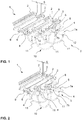
- FIG. 1 A partial area of a bridging device 1 in a lamella construction is shown.
- the bridging device 1 bridges a building joint between two building parts (not shown).
- the bridging device 1 has a plurality of slats 2 which are movable relative to one another.
- the bridging device 1 has a hydraulic control device 3.
- the hydraulic control device 3 is provided for controlling the gap widths S between the slats 2.
- the hydraulic control device 3 consists of three double-acting hydraulic cylinders 4.
- the hydraulic cylinders 4 are all constructed identically, so that the structure of a hydraulic cylinder 4 is described below.
- the hydraulic cylinder 4 has a piston 5 and a piston rod 6, which is connected to the piston 5 in a thrust-resistant manner.
- the piston 5 defines a first (variable) working volume 7a and a second (variable) working volume 7b in the hydraulic cylinder 4.
- Each hydraulic cylinder 4 is connected to a lamella 2 (or an edge support (not shown here) on the structural part).
- the hydraulic cylinder 4 is fixed to the plate 2 by means of a clamp 8.
- the clamp 8 is designed such that the hydraulic cylinder 4 is rotatably mounted about its vertical axis and about its transverse axis.
- the hydraulic cylinder 4 is a synchronous cylinder in that the piston rod 6 extends on both sides of the piston 5.
- the piston rod 6 is articulated at one end 9 to a second plate 2.
- the end 9 of the piston rod 6 is articulated to the lamella 2, which is directly adjacent to the lamella 2, on which the hydraulic cylinder 4 having the piston rod 6 is arranged.
- the hydraulic cylinders 4 are connected to one another via a hydraulic connection 10.
- the hydraulic connection 10 consists of three hoses 11, the ends of which are each hydraulically connected to a working volume 7a, 7b of a hydraulic cylinder 4 via a coupling 12.
- a first working volume 7a of a hydraulic cylinder 4 is always hydraulically connected to the second working volume 7b of another hydraulic cylinder 4 via a hose 11. This creates a hydraulic ring closure between the hydraulic cylinders 4.
- the hydraulic ring closure of the hydraulic cylinders 4 requires a uniform gap width S between adjacent slats 2 or between a slat 2 and the (not shown) edge support of a part of a building or bridge. Since the total volume of a hydraulic cylinder 4 always consists of the first working volume 7a and the second working volume 7b, the total volume remains constant when the piston 5 - and therefore also the piston rod 6 - moves. Furthermore, the total volume also corresponds to the sum of the volume of the first working volume 7a of a hydraulic cylinder 4 and the volume of the second working volume 7b of the other hydraulic cylinder 4 connected thereto via the hose 11.
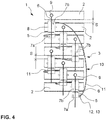
- a second embodiment is shown as a plan view.
- This exemplary embodiment essentially corresponds to that in FIG 1 and 2 Embodiment shown, wherein the hydraulic control device 3 has a total of six hydraulic cylinders 4. A total of seven lamellae 2 or five lamellae 2 and two edge supports are controlled via these six hydraulic cylinders 4.
- the first working volume 7a of a hydraulic cylinder 4 for example that in FIG Fig. 3 and Fig. 4 as the bottom hydraulic cylinder 4
- the second working volume 7b of the directly adjacent hydraulic cylinder 4 hydraulically connected via the hose 11
- this promotes clarity and allows an improved response behavior, since the volumes in the tubes 11 can be kept low.
- the gap width S both when the bridging device 1 has moved apart (cf. Fig. 3 ) as well as in the closed state of the bridging device 1 (cf. Fig. 4 ) is identical between the slats 2 or between a slat 2 and an edge support.
- the second exemplary embodiment of the bridging device 1 differs from that in FIG 1 and 2
- the embodiment shown is also characterized in that the hydraulic cylinder 4 shown at the bottom has a further connection 13 for an external (not shown) pump in the area of the coupling 12 of the first working volume 7a.
- a this connection 13 adjacent lamellae 2 of the bridging device 1 can be moved apart or moved together in a targeted manner by changing the operating pressure of the hydraulic control device 3 at the corresponding point via the pump. This can be necessary for function tests or maintenance work, for example.
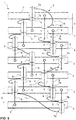
- FIG Fig. 5 A third exemplary embodiment of a bridging device 1 according to the invention in plan view is shown in FIG Fig. 5 shown.
- the bridging device 1 largely corresponds to that in FIG Fig. 3 Bridging device 1 shown, wherein the hydraulic control device 3 has a total of twelve hydraulic cylinders 4.
- the hydraulic control device 3 has a total of twelve hydraulic cylinders 4.
- the twelve hydraulic cylinders 4 are also connected via a hydraulic connection 10 Hoses 11 connected to a hydraulic ring closure.
- the first working volume 7a of a hydraulic cylinder 4 is connected to the second working volume 7b of another hydraulic cylinder 4.
- the embodiment shown here is a lamella 2 controlled by two hydraulic cylinders 4.
- two piston rods 6 are each hingedly connected at their ends 9 to the five central lamellae 2 (ie not to the edge supports, which are formed by the two outer lamellae 2 in this exemplary embodiment).
- Such double actuation of the slats 2 by the hydraulic control device 3 is advantageous in the case of relatively large bridging devices 1, for example in order to prevent the slats 2 from tilting in the case of wide structural joints to be bridged.
- FIG. 6 A fourth exemplary embodiment of a bridging device 1 according to the invention is shown.
- the bridging device 1 has a total of four separate hydraulic control devices 3, each of which in turn has three double-acting hydraulic cylinders 4.
- the three hydraulic cylinders 4 of each hydraulic control device 1 are connected via a hydraulic connection 10 by means of hoses 11 to form a hydraulic ring closure.
- a plurality of hydraulic control devices 3 with hydraulic ring closure are provided in this exemplary embodiment.
- a monitoring device 14 is provided in this sixth exemplary embodiment.
- This monitoring device 14 monitors the operating pressure of the hydraulic control devices 3.
- the hydraulic connection 10 is monitored via corresponding sensors 15. If a drop in pressure within the hydraulic connection 10 is detected, the monitoring device 14 indicates this. This is indicated as an example with dash-dotted lines for the uppermost hydraulic control device 3 shown. Of course, the monitoring device 14 monitors all hydraulic control devices 3 of the bridging device 1.
- the monitoring device 14 is designed to recognize short-term pressure fluctuations as a result of the movement of the structural parts.
- the monitoring device 14 shows no leakage in the event of these short-term pressure changes.
- the monitoring device 14 can only indicate a leak if the operating pressure does not correspond to the target pressure over a certain period of time. In this way, a gradual drop in operating pressure can be detected early.
- flow resistances 16 are also provided in the hydraulic connection 10 in the hydraulic control device 3 shown as the lowest.
- the flow resistances 16 are arranged as orifices in the tubes 11.
- the Flow resistances can specifically make the hydraulic control device 3 slow, so that short-term loads do not lead to any movement in the bridging device 1. This is relevant if the hydraulic control device 3, as shown, does not require any hydraulic preload (cf. also here Fig. 9 ).
- several flow resistances 16 can be provided. It is also conceivable that only one flow resistance 16 is provided. It is also conceivable that the flow resistance 16 is designed as a valve unit on the clutch 12.
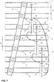
- FIG Fig. 7 A fifth exemplary embodiment of a bridging device 1 according to the invention is shown in FIG Fig. 7 shown.
- the hydraulic control device 3 is used to support a mechanical control device 17 in the form of a swivel crossmember.
- the swivel traverse 17 primarily controls the gap widths S between the slats 2 in a conventional and known manner.
- the hydraulic control device 3 in this exemplary embodiment consists of three hydraulic cylinders 4 and is essentially analogous to that in the first exemplary embodiment according to FIG Fig. 1 shown hydraulic control device 3 constructed. The difference can be seen in the fact that the hydraulic control device 3 controls only every second lamella 2 according to the fifth exemplary embodiment.
- the hydraulic control device 3 is therefore provided to support the swivel crossmember 17 and minimizes the possibility of incorrect control.
- This fifth exemplary embodiment is particularly suitable as a retrofit solution for existing bridging devices 1, since the actual control of the gap widths S takes place mechanically via the swivel cross member 17. Nevertheless, incorrect controls can be largely avoided.
- FIG. 8 A sixth exemplary embodiment of a bridging device 1 according to the invention is shown.
- the bridging device 1 has an analogous to that in FIG Fig. 7 Embodiment shown a mechanical control device 17 in the form of a swivel crossbar.
- the hydraulic control device 3 is used to support this.
- the difference to that in Fig. 7 Bridging device 1 shown consists in that the hydraulic control device has two first hydraulic cylinders 4a with a first cross section and two second hydraulic cylinders 4b with a second cross section. As shown, the first hydraulic cylinders 4a control the directly adjacent lamella 2, whereas the second hydraulic cylinders 4b control the second lamella 2.
- the shorter control stroke necessary for this with a correspondingly shorter piston rod 6 of the first hydraulic cylinders 4a is achieved by a larger cross section compared to the second hydraulic cylinder 4b.
- the hydraulic ring closure of the hydraulic cylinders 4a, 4b results from the constant product of cross-sectional area and piston stroke, which is identical for the first hydraulic cylinders 4a and for the second hydraulic cylinders 4b. Incorrect controls, in particular in the area of the first hydraulic cylinders 4a, are thus largely avoided.
- a hydraulic control device 3 designed in this way for support A mechanical control device 17 or an elastic control device is particularly suitable for bridging devices 1 with a longitudinal gradient.
- a sixth embodiment of a bridging device 1 according to the invention is shown, in which the hydraulic control device 3 is hydraulically preloaded, that is to say has an increased operating pressure. Due to the hydraulic preload, the hydraulic control device 3 responds particularly quickly and precisely.
- the hydraulic control device 3 essentially corresponds to that in FIG Fig. 1 shown hydraulic control device 3, wherein the hydraulic control device 3 has a hydraulic accumulator 18 with gas tensioning device.
- the hydraulic accumulator 18 can be a membrane-bubble or piston accumulator, for example.
- the hydraulic accumulator 18 is connected via a spring-loaded orifice check valve 19 to the hydraulic control device 10 via corresponding connecting lines 20, which can be connected to a hose 11 as shown.
- a compensating volume is thus created, as a result of which, for example, a temperature-related change in volume of the hydraulic fluid can be compensated. An inadmissible increase or decrease in the operating pressure is therefore prevented.
Landscapes
- Engineering & Computer Science (AREA)
- Architecture (AREA)
- Civil Engineering (AREA)
- Structural Engineering (AREA)
- Actuator (AREA)
- Bridges Or Land Bridges (AREA)
- Buildings Adapted To Withstand Abnormal External Influences (AREA)
- Road Paving Structures (AREA)
Claims (17)
- Dispositif de pontage (1) du type à poutre intermédiaire pour un joint de construction entre un premier élément de construction et un deuxième élément de construction, comprenant plusieurs poutres intermédiaires (2) et au moins un dispositif de commande hydraulique (3) pour commander l'écartement (S) entre les poutres intermédiaires (2), ledit dispositif de commande hydraulique (3) comprenant des vérins hydrauliques à double effet (4) dont chacun comporte un piston mobile (5) et une tige de piston (6) disposée sur le piston (5), chaque vérin hydraulique (4) étant disposé sur une poutre intermédiaire (2) et chaque tige de piston (6) étant couplée à une autre poutre intermédiaire (2), et le piston (5) définissant un premier volume de travail (7a) et un deuxième volume de travail (7b) du vérin hydraulique (4) correspondant,
caractérisé en ce que
ledit dispositif de commande hydraulique (3) comprend au moins trois vérins hydrauliques à double effet (4) qui sont en communication l'un avec l'autre par un organe de communication hydraulique (10) en mettant en communication hydraulique le premier volume de travail (7a) de chaque vérin hydraulique (4) avec le deuxième volume de travail (7b) d'un autre vérin hydraulique (4) de façon qu'une boucle fermée hydraulique entre lesdits au moins trois vérins hydrauliques (4) est générée. - Dispositif de pontage (1) selon la revendication 1,
caractérisé en ce que
ledit dispositif de commande hydraulique (3) est adapté pour permettre des mouvements de compensation définis. - Dispositif de pontage (1) selon l'une quelconque des revendications précédentes,
caractérisé en ce que
l'organe de communication hydraulique (10) comprend au moins un élément de résistance hydraulique (16). - Dispositif de pontage (1) selon la revendication 3,
caractérisé en ce que
ledit au moins un élément de résistance hydraulique (16) est disposé entre le premier volume de travail (7a) d'un vérin hydraulique (4) et le deuxième volume de travail (7b) d'un autre vérin hydraulique (4). - Dispositif de pontage (1) selon la revendication 1,
caractérisé en ce que
ledit dispositif de commande hydraulique (3) est pré-pressurisé de façon hydraulique. - Dispositif de pontage (1) selon l'une quelconque des revendications précédentes,
caractérisé en ce que
ledit dispositif de pontage (1) comprend au moins un accumulateur hydraulique (18). - Dispositif de pontage (1) selon la revendication 6,
caractérisé en ce que
ledit au moins un accumulateur hydraulique (18) comprend un dispositif de pré-pressurisation à gaz, et il est en particulier un accumulateur hydraulique à ballon, à piston ou à membrane. - Dispositif de pontage (1) selon l'une quelconque des revendications précédentes 6 ou 7,
caractérisé en ce que
ledit au moins un accumulateur hydraulique (18) est en communication avec ledit dispositif de commande hydraulique (3) via un clapet anti-retour (19). - Dispositif de pontage (1) selon la revendication 8,
caractérisé en ce que
ledit clapet anti-retour (19) est un clapet antiretour à battant. - Dispositif de pontage (1) selon l'une quelconque des revendications précédentes,
caractérisé en ce que
ledit dispositif de commande hydraulique (3) comprend des tuyaux (11) pour mettre en communication les volumes de travail (7a, 7b) des vérins hydrauliques (4). - Dispositif de pontage (1) selon la revendication 10,
caractérisé en ce que
les tuyaux (11) sont raccordés aux vérins hydrauliques (4) par des coupleurs enfichables (12). - Dispositif de pontage (1) selon l'une quelconque des revendications précédentes,
caractérisé en ce que
au moins une tige de piston (6) est reliée de façon articulée à la poutre intermédiaire (2). - Dispositif de pontage (1) selon l'une quelconque des revendications précédentes,
caractérisé en ce que
ledit dispositif de commande hydraulique (3) comprend au moins un raccord (13) pour une pompe. - Dispositif de pontage (1) selon l'une quelconque des revendications précédentes,
caractérisé en ce que
ledit dispositif de pontage (1) comprend un dispositif de surveillance (14) pour la détection de variations de pression. - Dispositif de pontage (1) selon l'une quelconque des revendications précédentes,
caractérisé en ce que
ledit dispositif de pontage (1) comprend au moins un dispositif de commande mécanique et/ou élastique (17), en particulier une traverse pivotante. - Dispositif de pontage (1) selon la revendication 15,
caractérisé en ce que
au moins un vérin hydraulique est un premier vérin hydraulique (4a) présentant une première section transversale, un autre vérin hydraulique (4b) étant un deuxième vérin hydraulique (4a) présentant une deuxième section transversale, et ladite première section transversale étant différent de ladite deuxième section transversale. - Dispositif de pontage (1) selon la revendication 16,
caractérisé en ce que
la somme du premier volume de travail (7a) et du deuxième volume de travail (7b) du premier vérin hydraulique (4a) est égal à la somme du premier volume de travail (7a) et du deuxième volume de travail (7b) du deuxième vérin hydraulique (4b).
Applications Claiming Priority (2)
| Application Number | Priority Date | Filing Date | Title |
|---|---|---|---|
| DE102016219852.1A DE102016219852A1 (de) | 2016-10-12 | 2016-10-12 | Überbrückungsvorrichtung für eine Bauwerksfuge mit einer hydraulischen Steuervorrichtung |
| PCT/EP2017/071169 WO2018068935A1 (fr) | 2016-10-12 | 2017-08-22 | Dispositif de recouvrement pour un joint de construction, muni d'un dispositif de commande hydraulique |
Publications (2)
| Publication Number | Publication Date |
|---|---|
| EP3449060A1 EP3449060A1 (fr) | 2019-03-06 |
| EP3449060B1 true EP3449060B1 (fr) | 2020-05-13 |
Family
ID=59683592
Family Applications (1)
| Application Number | Title | Priority Date | Filing Date |
|---|---|---|---|
| EP17755193.4A Active EP3449060B1 (fr) | 2016-10-12 | 2017-08-22 | Dispositif de recouvrement pour un joint de construction, muni d'un dispositif de commande hydraulique |
Country Status (8)
| Country | Link |
|---|---|
| US (1) | US10794020B2 (fr) |
| EP (1) | EP3449060B1 (fr) |
| JP (1) | JP6935429B2 (fr) |
| DE (1) | DE102016219852A1 (fr) |
| ES (1) | ES2800342T3 (fr) |
| IL (1) | IL263236B (fr) |
| PT (1) | PT3449060T (fr) |
| WO (1) | WO2018068935A1 (fr) |
Families Citing this family (3)
| Publication number | Priority date | Publication date | Assignee | Title |
|---|---|---|---|---|
| IT201800007848A1 (it) * | 2018-08-03 | 2020-02-03 | Univergom Srl | Giunto di dilatazione a grande escursione |
| CN113832843A (zh) * | 2021-10-20 | 2021-12-24 | 中铁大桥勘测设计院集团有限公司 | 一种桥梁结构及伸缩缝的结构 |
| CN114922073B (zh) * | 2022-05-19 | 2023-09-05 | 中电建路桥集团有限公司 | 一种快速拆卸贝雷盘扣支架体系中分配梁的装置 |
Family Cites Families (10)
| Publication number | Priority date | Publication date | Assignee | Title |
|---|---|---|---|---|
| DE2060482A1 (de) | 1970-12-09 | 1972-07-06 | Maurer Friedrich Soehne | UEberbrueckungsvorrichtung fuer Dehnungsfugen |
| AT310233B (de) * | 1971-01-26 | 1973-09-25 | Rheinstahl Ag | Fahrbahnübergang für Dehnfugen an Straßenbrücken od.dgl. |
| US3732021A (en) * | 1971-03-08 | 1973-05-08 | Brown Co D S | Modular expansion joint |
| AT326720B (de) | 1973-05-07 | 1975-12-29 | Honel Holdings Ag | Abgedichtete dehnungsfuge in einer fahrbahn |
| CH666303A5 (en) | 1984-09-17 | 1988-07-15 | Kober Ag | Expansion joint rib interval control equipment - comprises thrust springs and rigid links forming continuous chain with them |
| US5319712A (en) * | 1993-08-26 | 1994-06-07 | Motorola, Inc. | Method and apparatus for providing cryptographic protection of a data stream in a communication system |
| KR100283364B1 (ko) * | 1998-05-09 | 2001-03-02 | 황해웅 | 신축 이음장치 |
| CA2423578C (fr) * | 2002-04-02 | 2010-02-16 | Mbt Holding Ag | Joints de dilatation permettant des mouvements importants dans plusieurs directions |
| US7252454B2 (en) * | 2003-10-31 | 2007-08-07 | Paul Bradford | Expansion joint system including damping means |
| US20080148499A1 (en) * | 2006-12-13 | 2008-06-26 | Construction Research & Technology Gmbh | Expansion joint system |
-
2016
- 2016-10-12 DE DE102016219852.1A patent/DE102016219852A1/de not_active Withdrawn
-
2017
- 2017-08-22 WO PCT/EP2017/071169 patent/WO2018068935A1/fr unknown
- 2017-08-22 EP EP17755193.4A patent/EP3449060B1/fr active Active
- 2017-08-22 ES ES17755193T patent/ES2800342T3/es active Active
- 2017-08-22 US US16/304,777 patent/US10794020B2/en active Active
- 2017-08-22 JP JP2018563882A patent/JP6935429B2/ja active Active
- 2017-08-22 PT PT177551934T patent/PT3449060T/pt unknown
-
2018
- 2018-11-22 IL IL263236A patent/IL263236B/en unknown
Non-Patent Citations (1)
| Title |
|---|
| None * |
Also Published As
| Publication number | Publication date |
|---|---|
| JP2019530815A (ja) | 2019-10-24 |
| WO2018068935A1 (fr) | 2018-04-19 |
| US10794020B2 (en) | 2020-10-06 |
| PT3449060T (pt) | 2020-07-28 |
| US20200270828A1 (en) | 2020-08-27 |
| DE102016219852A1 (de) | 2018-04-12 |
| EP3449060A1 (fr) | 2019-03-06 |
| ES2800342T3 (es) | 2020-12-29 |
| JP6935429B2 (ja) | 2021-09-15 |
| IL263236B (en) | 2021-10-31 |
Similar Documents
| Publication | Publication Date | Title |
|---|---|---|
| EP2101963B1 (fr) | Mécanisme vermiculaire | |
| EP3449060B1 (fr) | Dispositif de recouvrement pour un joint de construction, muni d'un dispositif de commande hydraulique | |
| DE2923027C2 (de) | Vorrichtung zum Betätigen einer Lamellenfederkupplung eines Kraftfahrzeuges | |
| DE4110258A1 (de) | Elastomere halterung sowie aufhaengung mit einer solchen halterung | |
| EP3074572B1 (fr) | Dispositif d'enjambement | |
| DE10011767C1 (de) | Kolben-Zylinderaggregat | |
| EP0523434A1 (fr) | Organe de positionnement actionné par pression, en particulier pour un dispositif de levage, de halage et de poussage | |
| CH630709A5 (en) | Application device for friction brakes, in particular those of rail vehicles | |
| EP1843048A2 (fr) | Dispositif de vérin | |
| EP0728648B1 (fr) | Train articulé | |
| DE3200842C2 (de) | Blockiereinrichtung für einen Axialkompensator für Rohre | |
| DE2607212C3 (de) | Kern zur Bildung eines Hohlraumes in in einer Gießform herzustellenden plattenartigen Bauelementen | |
| DE3836103C2 (fr) | ||
| EP1033498B1 (fr) | Procédé pour la commande d'un cylindre de positionnement à course longue | |
| DE20309196U1 (de) | Schwenkvorrichtung und Schwenksystem | |
| DE102016110674B3 (de) | Scharniergelenkstruktur | |
| DE29906627U1 (de) | Betätigungseinrichtung | |
| EP3967568B1 (fr) | Commande active de train de roues pour un véhicule ferroviaire | |
| DE102015218778B4 (de) | Hydraulischer Getriebeaktor | |
| DE102018105102A1 (de) | Fangzylinder sowie Lasthebemittel mit einem Fangzylinder | |
| DE1530207C3 (de) | Hydraulisch gedämpfte Stoßaufnahmevorrichtung für Eisenbahnwagen | |
| EP3770445B1 (fr) | Arrangement avec un vérin pneumatique ou hydraulique | |
| DE2234563C3 (de) | Stellanordnung zur Einstellung einer Steuerfläche | |
| DE1555250C3 (de) | Schreitwerk für die Fortbewegung von schweren Lasten | |
| EP3770444A1 (fr) | Vérin pneumatique ou hydraulique |
Legal Events
| Date | Code | Title | Description |
|---|---|---|---|
| STAA | Information on the status of an ep patent application or granted ep patent |
Free format text: STATUS: UNKNOWN |
|
| STAA | Information on the status of an ep patent application or granted ep patent |
Free format text: STATUS: THE INTERNATIONAL PUBLICATION HAS BEEN MADE |
|
| PUAI | Public reference made under article 153(3) epc to a published international application that has entered the european phase |
Free format text: ORIGINAL CODE: 0009012 |
|
| STAA | Information on the status of an ep patent application or granted ep patent |
Free format text: STATUS: REQUEST FOR EXAMINATION WAS MADE |
|
| 17P | Request for examination filed |
Effective date: 20181128 |
|
| AK | Designated contracting states |
Kind code of ref document: A1 Designated state(s): AL AT BE BG CH CY CZ DE DK EE ES FI FR GB GR HR HU IE IS IT LI LT LU LV MC MK MT NL NO PL PT RO RS SE SI SK SM TR |
|
| AX | Request for extension of the european patent |
Extension state: BA ME |
|
| GRAP | Despatch of communication of intention to grant a patent |
Free format text: ORIGINAL CODE: EPIDOSNIGR1 |
|
| STAA | Information on the status of an ep patent application or granted ep patent |
Free format text: STATUS: GRANT OF PATENT IS INTENDED |
|
| DAV | Request for validation of the european patent (deleted) | ||
| DAX | Request for extension of the european patent (deleted) | ||
| INTG | Intention to grant announced |
Effective date: 20191210 |
|
| GRAS | Grant fee paid |
Free format text: ORIGINAL CODE: EPIDOSNIGR3 |
|
| GRAA | (expected) grant |
Free format text: ORIGINAL CODE: 0009210 |
|
| STAA | Information on the status of an ep patent application or granted ep patent |
Free format text: STATUS: THE PATENT HAS BEEN GRANTED |
|
| AK | Designated contracting states |
Kind code of ref document: B1 Designated state(s): AL AT BE BG CH CY CZ DE DK EE ES FI FR GB GR HR HU IE IS IT LI LT LU LV MC MK MT NL NO PL PT RO RS SE SI SK SM TR |
|
| REG | Reference to a national code |
Ref country code: GB Ref legal event code: FG4D Free format text: NOT ENGLISH |
|
| REG | Reference to a national code |
Ref country code: CH Ref legal event code: EP |
|
| REG | Reference to a national code |
Ref country code: DE Ref legal event code: R096 Ref document number: 502017005316 Country of ref document: DE |
|
| REG | Reference to a national code |
Ref country code: AT Ref legal event code: REF Ref document number: 1270436 Country of ref document: AT Kind code of ref document: T Effective date: 20200615 |
|
| REG | Reference to a national code |
Ref country code: CH Ref legal event code: NV Representative=s name: TROESCH SCHEIDEGGER WERNER AG, CH |
|
| REG | Reference to a national code |
Ref country code: PT Ref legal event code: SC4A Ref document number: 3449060 Country of ref document: PT Date of ref document: 20200728 Kind code of ref document: T Free format text: AVAILABILITY OF NATIONAL TRANSLATION Effective date: 20200723 |
|
| REG | Reference to a national code |
Ref country code: LT Ref legal event code: MG4D |
|
| REG | Reference to a national code |
Ref country code: GR Ref legal event code: EP Ref document number: 20200402145 Country of ref document: GR Effective date: 20201014 Ref country code: NL Ref legal event code: MP Effective date: 20200513 |
|
| PG25 | Lapsed in a contracting state [announced via postgrant information from national office to epo] |
Ref country code: LT Free format text: LAPSE BECAUSE OF FAILURE TO SUBMIT A TRANSLATION OF THE DESCRIPTION OR TO PAY THE FEE WITHIN THE PRESCRIBED TIME-LIMIT Effective date: 20200513 Ref country code: FI Free format text: LAPSE BECAUSE OF FAILURE TO SUBMIT A TRANSLATION OF THE DESCRIPTION OR TO PAY THE FEE WITHIN THE PRESCRIBED TIME-LIMIT Effective date: 20200513 Ref country code: SE Free format text: LAPSE BECAUSE OF FAILURE TO SUBMIT A TRANSLATION OF THE DESCRIPTION OR TO PAY THE FEE WITHIN THE PRESCRIBED TIME-LIMIT Effective date: 20200513 Ref country code: NO Free format text: LAPSE BECAUSE OF FAILURE TO SUBMIT A TRANSLATION OF THE DESCRIPTION OR TO PAY THE FEE WITHIN THE PRESCRIBED TIME-LIMIT Effective date: 20200813 Ref country code: IS Free format text: LAPSE BECAUSE OF FAILURE TO SUBMIT A TRANSLATION OF THE DESCRIPTION OR TO PAY THE FEE WITHIN THE PRESCRIBED TIME-LIMIT Effective date: 20200913 |
|
| PG25 | Lapsed in a contracting state [announced via postgrant information from national office to epo] |
Ref country code: RS Free format text: LAPSE BECAUSE OF FAILURE TO SUBMIT A TRANSLATION OF THE DESCRIPTION OR TO PAY THE FEE WITHIN THE PRESCRIBED TIME-LIMIT Effective date: 20200513 Ref country code: HR Free format text: LAPSE BECAUSE OF FAILURE TO SUBMIT A TRANSLATION OF THE DESCRIPTION OR TO PAY THE FEE WITHIN THE PRESCRIBED TIME-LIMIT Effective date: 20200513 Ref country code: LV Free format text: LAPSE BECAUSE OF FAILURE TO SUBMIT A TRANSLATION OF THE DESCRIPTION OR TO PAY THE FEE WITHIN THE PRESCRIBED TIME-LIMIT Effective date: 20200513 |
|
| PG25 | Lapsed in a contracting state [announced via postgrant information from national office to epo] |
Ref country code: AL Free format text: LAPSE BECAUSE OF FAILURE TO SUBMIT A TRANSLATION OF THE DESCRIPTION OR TO PAY THE FEE WITHIN THE PRESCRIBED TIME-LIMIT Effective date: 20200513 Ref country code: NL Free format text: LAPSE BECAUSE OF FAILURE TO SUBMIT A TRANSLATION OF THE DESCRIPTION OR TO PAY THE FEE WITHIN THE PRESCRIBED TIME-LIMIT Effective date: 20200513 |
|
| PG25 | Lapsed in a contracting state [announced via postgrant information from national office to epo] |
Ref country code: CZ Free format text: LAPSE BECAUSE OF FAILURE TO SUBMIT A TRANSLATION OF THE DESCRIPTION OR TO PAY THE FEE WITHIN THE PRESCRIBED TIME-LIMIT Effective date: 20200513 Ref country code: DK Free format text: LAPSE BECAUSE OF FAILURE TO SUBMIT A TRANSLATION OF THE DESCRIPTION OR TO PAY THE FEE WITHIN THE PRESCRIBED TIME-LIMIT Effective date: 20200513 Ref country code: EE Free format text: LAPSE BECAUSE OF FAILURE TO SUBMIT A TRANSLATION OF THE DESCRIPTION OR TO PAY THE FEE WITHIN THE PRESCRIBED TIME-LIMIT Effective date: 20200513 Ref country code: SM Free format text: LAPSE BECAUSE OF FAILURE TO SUBMIT A TRANSLATION OF THE DESCRIPTION OR TO PAY THE FEE WITHIN THE PRESCRIBED TIME-LIMIT Effective date: 20200513 |
|
| REG | Reference to a national code |
Ref country code: DE Ref legal event code: R097 Ref document number: 502017005316 Country of ref document: DE |
|
| PG25 | Lapsed in a contracting state [announced via postgrant information from national office to epo] |
Ref country code: SK Free format text: LAPSE BECAUSE OF FAILURE TO SUBMIT A TRANSLATION OF THE DESCRIPTION OR TO PAY THE FEE WITHIN THE PRESCRIBED TIME-LIMIT Effective date: 20200513 Ref country code: PL Free format text: LAPSE BECAUSE OF FAILURE TO SUBMIT A TRANSLATION OF THE DESCRIPTION OR TO PAY THE FEE WITHIN THE PRESCRIBED TIME-LIMIT Effective date: 20200513 |
|
| PLBE | No opposition filed within time limit |
Free format text: ORIGINAL CODE: 0009261 |
|
| STAA | Information on the status of an ep patent application or granted ep patent |
Free format text: STATUS: NO OPPOSITION FILED WITHIN TIME LIMIT |
|
| PG25 | Lapsed in a contracting state [announced via postgrant information from national office to epo] |
Ref country code: MC Free format text: LAPSE BECAUSE OF FAILURE TO SUBMIT A TRANSLATION OF THE DESCRIPTION OR TO PAY THE FEE WITHIN THE PRESCRIBED TIME-LIMIT Effective date: 20200513 |
|
| 26N | No opposition filed |
Effective date: 20210216 |
|
| PG25 | Lapsed in a contracting state [announced via postgrant information from national office to epo] |
Ref country code: LU Free format text: LAPSE BECAUSE OF NON-PAYMENT OF DUE FEES Effective date: 20200822 |
|
| REG | Reference to a national code |
Ref country code: BE Ref legal event code: MM Effective date: 20200831 |
|
| PG25 | Lapsed in a contracting state [announced via postgrant information from national office to epo] |
Ref country code: SI Free format text: LAPSE BECAUSE OF FAILURE TO SUBMIT A TRANSLATION OF THE DESCRIPTION OR TO PAY THE FEE WITHIN THE PRESCRIBED TIME-LIMIT Effective date: 20200513 |
|
| PG25 | Lapsed in a contracting state [announced via postgrant information from national office to epo] |
Ref country code: IE Free format text: LAPSE BECAUSE OF NON-PAYMENT OF DUE FEES Effective date: 20200822 Ref country code: BE Free format text: LAPSE BECAUSE OF NON-PAYMENT OF DUE FEES Effective date: 20200831 |
|
| GBPC | Gb: european patent ceased through non-payment of renewal fee |
Effective date: 20210822 |
|
| PG25 | Lapsed in a contracting state [announced via postgrant information from national office to epo] |
Ref country code: MT Free format text: LAPSE BECAUSE OF FAILURE TO SUBMIT A TRANSLATION OF THE DESCRIPTION OR TO PAY THE FEE WITHIN THE PRESCRIBED TIME-LIMIT Effective date: 20200513 Ref country code: CY Free format text: LAPSE BECAUSE OF FAILURE TO SUBMIT A TRANSLATION OF THE DESCRIPTION OR TO PAY THE FEE WITHIN THE PRESCRIBED TIME-LIMIT Effective date: 20200513 |
|
| PG25 | Lapsed in a contracting state [announced via postgrant information from national office to epo] |
Ref country code: MK Free format text: LAPSE BECAUSE OF FAILURE TO SUBMIT A TRANSLATION OF THE DESCRIPTION OR TO PAY THE FEE WITHIN THE PRESCRIBED TIME-LIMIT Effective date: 20200513 |
|
| PG25 | Lapsed in a contracting state [announced via postgrant information from national office to epo] |
Ref country code: GB Free format text: LAPSE BECAUSE OF NON-PAYMENT OF DUE FEES Effective date: 20210822 |
|
| REG | Reference to a national code |
Ref country code: AT Ref legal event code: MM01 Ref document number: 1270436 Country of ref document: AT Kind code of ref document: T Effective date: 20220822 |
|
| PG25 | Lapsed in a contracting state [announced via postgrant information from national office to epo] |
Ref country code: AT Free format text: LAPSE BECAUSE OF NON-PAYMENT OF DUE FEES Effective date: 20220822 |
|
| PGFP | Annual fee paid to national office [announced via postgrant information from national office to epo] |
Ref country code: TR Payment date: 20230815 Year of fee payment: 7 Ref country code: RO Payment date: 20230821 Year of fee payment: 7 Ref country code: IT Payment date: 20230831 Year of fee payment: 7 Ref country code: ES Payment date: 20230918 Year of fee payment: 7 Ref country code: CH Payment date: 20230902 Year of fee payment: 7 Ref country code: BG Payment date: 20230818 Year of fee payment: 7 |
|
| PGFP | Annual fee paid to national office [announced via postgrant information from national office to epo] |
Ref country code: PT Payment date: 20230817 Year of fee payment: 7 Ref country code: GR Payment date: 20230818 Year of fee payment: 7 Ref country code: FR Payment date: 20230822 Year of fee payment: 7 Ref country code: DE Payment date: 20230822 Year of fee payment: 7 |