EP3448641B1 - Cutting machine and method for slicing elastic strands, in particular meat strands - Google Patents
Cutting machine and method for slicing elastic strands, in particular meat strands Download PDFInfo
- Publication number
- EP3448641B1 EP3448641B1 EP17719602.9A EP17719602A EP3448641B1 EP 3448641 B1 EP3448641 B1 EP 3448641B1 EP 17719602 A EP17719602 A EP 17719602A EP 3448641 B1 EP3448641 B1 EP 3448641B1
- Authority
- EP
- European Patent Office
- Prior art keywords
- tube
- strand
- transversal
- longitudinal
- form tube
- Prior art date
- Legal status (The legal status is an assumption and is not a legal conclusion. Google has not performed a legal analysis and makes no representation as to the accuracy of the status listed.)
- Active
Links
- 238000005520 cutting process Methods 0.000 title claims description 152
- 235000013372 meat Nutrition 0.000 title claims description 149
- 238000000034 method Methods 0.000 title claims description 33
- 238000003825 pressing Methods 0.000 claims description 129
- 230000033001 locomotion Effects 0.000 claims description 52
- 230000006835 compression Effects 0.000 claims description 30
- 238000007906 compression Methods 0.000 claims description 30
- 238000013459 approach Methods 0.000 claims description 4
- 238000003780 insertion Methods 0.000 claims description 4
- 230000037431 insertion Effects 0.000 claims description 4
- 230000004323 axial length Effects 0.000 claims description 3
- 239000013013 elastic material Substances 0.000 claims description 3
- 238000004519 manufacturing process Methods 0.000 claims description 3
- 238000011144 upstream manufacturing Methods 0.000 claims description 2
- 238000007493 shaping process Methods 0.000 description 49
- 101100328887 Caenorhabditis elegans col-34 gene Proteins 0.000 description 21
- 238000013461 design Methods 0.000 description 16
- 239000000463 material Substances 0.000 description 13
- 238000005303 weighing Methods 0.000 description 12
- 238000000465 moulding Methods 0.000 description 11
- 230000008569 process Effects 0.000 description 11
- 241000972773 Aulopiformes Species 0.000 description 7
- 235000019515 salmon Nutrition 0.000 description 7
- 125000006850 spacer group Chemical group 0.000 description 6
- 230000002093 peripheral effect Effects 0.000 description 5
- 238000012545 processing Methods 0.000 description 5
- 230000001154 acute effect Effects 0.000 description 2
- 210000000988 bone and bone Anatomy 0.000 description 2
- 230000008859 change Effects 0.000 description 2
- 230000008878 coupling Effects 0.000 description 2
- 238000010168 coupling process Methods 0.000 description 2
- 238000005859 coupling reaction Methods 0.000 description 2
- 238000007789 sealing Methods 0.000 description 2
- 238000000926 separation method Methods 0.000 description 2
- BQCADISMDOOEFD-UHFFFAOYSA-N Silver Chemical compound [Ag] BQCADISMDOOEFD-UHFFFAOYSA-N 0.000 description 1
- 230000001133 acceleration Effects 0.000 description 1
- 230000009471 action Effects 0.000 description 1
- 235000015278 beef Nutrition 0.000 description 1
- 230000005540 biological transmission Effects 0.000 description 1
- 235000013351 cheese Nutrition 0.000 description 1
- 238000010276 construction Methods 0.000 description 1
- 230000001419 dependent effect Effects 0.000 description 1
- 238000001514 detection method Methods 0.000 description 1
- 239000000945 filler Substances 0.000 description 1
- 238000007654 immersion Methods 0.000 description 1
- 230000010354 integration Effects 0.000 description 1
- 230000003993 interaction Effects 0.000 description 1
- 230000001788 irregular Effects 0.000 description 1
- 210000003205 muscle Anatomy 0.000 description 1
- 235000015277 pork Nutrition 0.000 description 1
- 235000020989 red meat Nutrition 0.000 description 1
- 235000013580 sausages Nutrition 0.000 description 1
- 229910052709 silver Inorganic materials 0.000 description 1
- 239000004332 silver Substances 0.000 description 1
- 239000007787 solid Substances 0.000 description 1
Images


Classifications
-
- B—PERFORMING OPERATIONS; TRANSPORTING
- B26—HAND CUTTING TOOLS; CUTTING; SEVERING
- B26D—CUTTING; DETAILS COMMON TO MACHINES FOR PERFORATING, PUNCHING, CUTTING-OUT, STAMPING-OUT OR SEVERING
- B26D1/00—Cutting through work characterised by the nature or movement of the cutting member or particular materials not otherwise provided for; Apparatus or machines therefor; Cutting members therefor
- B26D1/01—Cutting through work characterised by the nature or movement of the cutting member or particular materials not otherwise provided for; Apparatus or machines therefor; Cutting members therefor involving a cutting member which does not travel with the work
- B26D1/12—Cutting through work characterised by the nature or movement of the cutting member or particular materials not otherwise provided for; Apparatus or machines therefor; Cutting members therefor involving a cutting member which does not travel with the work having a cutting member moving about an axis
- B26D1/14—Cutting through work characterised by the nature or movement of the cutting member or particular materials not otherwise provided for; Apparatus or machines therefor; Cutting members therefor involving a cutting member which does not travel with the work having a cutting member moving about an axis with a circular cutting member, e.g. disc cutter
- B26D1/143—Cutting through work characterised by the nature or movement of the cutting member or particular materials not otherwise provided for; Apparatus or machines therefor; Cutting members therefor involving a cutting member which does not travel with the work having a cutting member moving about an axis with a circular cutting member, e.g. disc cutter rotating about a stationary axis
-
- A—HUMAN NECESSITIES
- A22—BUTCHERING; MEAT TREATMENT; PROCESSING POULTRY OR FISH
- A22C—PROCESSING MEAT, POULTRY, OR FISH
- A22C17/00—Other devices for processing meat or bones
- A22C17/0006—Cutting or shaping meat
- A22C17/002—Producing portions of meat with predetermined characteristics, e.g. weight or particular dimensions
-
- A—HUMAN NECESSITIES
- A22—BUTCHERING; MEAT TREATMENT; PROCESSING POULTRY OR FISH
- A22C—PROCESSING MEAT, POULTRY, OR FISH
- A22C17/00—Other devices for processing meat or bones
- A22C17/0006—Cutting or shaping meat
- A22C17/0033—Cutting slices out of a piece of meat
-
- A—HUMAN NECESSITIES
- A22—BUTCHERING; MEAT TREATMENT; PROCESSING POULTRY OR FISH
- A22C—PROCESSING MEAT, POULTRY, OR FISH
- A22C17/00—Other devices for processing meat or bones
- A22C17/02—Apparatus for holding meat or bones while cutting
-
- A—HUMAN NECESSITIES
- A22—BUTCHERING; MEAT TREATMENT; PROCESSING POULTRY OR FISH
- A22C—PROCESSING MEAT, POULTRY, OR FISH
- A22C25/00—Processing fish ; Curing of fish; Stunning of fish by electric current; Investigating fish by optical means
- A22C25/08—Holding, guiding, or conveying fish before, during or after its preparation ; Devices for sizing fish; Automatically adapting conveyors or processing machines to the measured size
-
- A—HUMAN NECESSITIES
- A22—BUTCHERING; MEAT TREATMENT; PROCESSING POULTRY OR FISH
- A22C—PROCESSING MEAT, POULTRY, OR FISH
- A22C25/00—Processing fish ; Curing of fish; Stunning of fish by electric current; Investigating fish by optical means
- A22C25/10—Devices for threading fish on strings or the like
-
- A—HUMAN NECESSITIES
- A22—BUTCHERING; MEAT TREATMENT; PROCESSING POULTRY OR FISH
- A22C—PROCESSING MEAT, POULTRY, OR FISH
- A22C25/00—Processing fish ; Curing of fish; Stunning of fish by electric current; Investigating fish by optical means
- A22C25/18—Cutting fish into portions
-
- B—PERFORMING OPERATIONS; TRANSPORTING
- B26—HAND CUTTING TOOLS; CUTTING; SEVERING
- B26D—CUTTING; DETAILS COMMON TO MACHINES FOR PERFORATING, PUNCHING, CUTTING-OUT, STAMPING-OUT OR SEVERING
- B26D3/00—Cutting work characterised by the nature of the cut made; Apparatus therefor
- B26D3/16—Cutting rods or tubes transversely
-
- B—PERFORMING OPERATIONS; TRANSPORTING
- B26—HAND CUTTING TOOLS; CUTTING; SEVERING
- B26D—CUTTING; DETAILS COMMON TO MACHINES FOR PERFORATING, PUNCHING, CUTTING-OUT, STAMPING-OUT OR SEVERING
- B26D5/00—Arrangements for operating and controlling machines or devices for cutting, cutting-out, stamping-out, punching, perforating, or severing by means other than cutting
- B26D5/02—Means for moving the cutting member into its operative position for cutting
- B26D5/06—Means for moving the cutting member into its operative position for cutting by electrical means
-
- B—PERFORMING OPERATIONS; TRANSPORTING
- B26—HAND CUTTING TOOLS; CUTTING; SEVERING
- B26D—CUTTING; DETAILS COMMON TO MACHINES FOR PERFORATING, PUNCHING, CUTTING-OUT, STAMPING-OUT OR SEVERING
- B26D5/00—Arrangements for operating and controlling machines or devices for cutting, cutting-out, stamping-out, punching, perforating, or severing by means other than cutting
- B26D5/08—Means for actuating the cutting member to effect the cut
- B26D5/086—Electric, magnetic, piezoelectric, electro-magnetic means
-
- B—PERFORMING OPERATIONS; TRANSPORTING
- B26—HAND CUTTING TOOLS; CUTTING; SEVERING
- B26D—CUTTING; DETAILS COMMON TO MACHINES FOR PERFORATING, PUNCHING, CUTTING-OUT, STAMPING-OUT OR SEVERING
- B26D5/00—Arrangements for operating and controlling machines or devices for cutting, cutting-out, stamping-out, punching, perforating, or severing by means other than cutting
- B26D5/20—Arrangements for operating and controlling machines or devices for cutting, cutting-out, stamping-out, punching, perforating, or severing by means other than cutting with interrelated action between the cutting member and work feed
- B26D5/30—Arrangements for operating and controlling machines or devices for cutting, cutting-out, stamping-out, punching, perforating, or severing by means other than cutting with interrelated action between the cutting member and work feed having the cutting member controlled by scanning a record carrier
-
- B—PERFORMING OPERATIONS; TRANSPORTING
- B26—HAND CUTTING TOOLS; CUTTING; SEVERING
- B26D—CUTTING; DETAILS COMMON TO MACHINES FOR PERFORATING, PUNCHING, CUTTING-OUT, STAMPING-OUT OR SEVERING
- B26D7/00—Details of apparatus for cutting, cutting-out, stamping-out, punching, perforating, or severing by means other than cutting
- B26D7/01—Means for holding or positioning work
-
- B—PERFORMING OPERATIONS; TRANSPORTING
- B26—HAND CUTTING TOOLS; CUTTING; SEVERING
- B26D—CUTTING; DETAILS COMMON TO MACHINES FOR PERFORATING, PUNCHING, CUTTING-OUT, STAMPING-OUT OR SEVERING
- B26D7/00—Details of apparatus for cutting, cutting-out, stamping-out, punching, perforating, or severing by means other than cutting
- B26D7/06—Arrangements for feeding or delivering work of other than sheet, web, or filamentary form
- B26D7/0608—Arrangements for feeding or delivering work of other than sheet, web, or filamentary form by pushers
-
- B—PERFORMING OPERATIONS; TRANSPORTING
- B26—HAND CUTTING TOOLS; CUTTING; SEVERING
- B26D—CUTTING; DETAILS COMMON TO MACHINES FOR PERFORATING, PUNCHING, CUTTING-OUT, STAMPING-OUT OR SEVERING
- B26D7/00—Details of apparatus for cutting, cutting-out, stamping-out, punching, perforating, or severing by means other than cutting
- B26D7/06—Arrangements for feeding or delivering work of other than sheet, web, or filamentary form
- B26D7/0625—Arrangements for feeding or delivering work of other than sheet, web, or filamentary form by endless conveyors, e.g. belts
-
- B—PERFORMING OPERATIONS; TRANSPORTING
- B26—HAND CUTTING TOOLS; CUTTING; SEVERING
- B26D—CUTTING; DETAILS COMMON TO MACHINES FOR PERFORATING, PUNCHING, CUTTING-OUT, STAMPING-OUT OR SEVERING
- B26D7/00—Details of apparatus for cutting, cutting-out, stamping-out, punching, perforating, or severing by means other than cutting
- B26D7/06—Arrangements for feeding or delivering work of other than sheet, web, or filamentary form
- B26D7/0641—Arrangements for feeding or delivering work of other than sheet, web, or filamentary form using chutes, hoppers, magazines
-
- B—PERFORMING OPERATIONS; TRANSPORTING
- B26—HAND CUTTING TOOLS; CUTTING; SEVERING
- B26D—CUTTING; DETAILS COMMON TO MACHINES FOR PERFORATING, PUNCHING, CUTTING-OUT, STAMPING-OUT OR SEVERING
- B26D7/00—Details of apparatus for cutting, cutting-out, stamping-out, punching, perforating, or severing by means other than cutting
- B26D7/06—Arrangements for feeding or delivering work of other than sheet, web, or filamentary form
- B26D7/0683—Arrangements for feeding or delivering work of other than sheet, web, or filamentary form specially adapted for elongated articles
-
- B—PERFORMING OPERATIONS; TRANSPORTING
- B26—HAND CUTTING TOOLS; CUTTING; SEVERING
- B26D—CUTTING; DETAILS COMMON TO MACHINES FOR PERFORATING, PUNCHING, CUTTING-OUT, STAMPING-OUT OR SEVERING
- B26D7/00—Details of apparatus for cutting, cutting-out, stamping-out, punching, perforating, or severing by means other than cutting
- B26D7/08—Means for treating work or cutting member to facilitate cutting
-
- B—PERFORMING OPERATIONS; TRANSPORTING
- B26—HAND CUTTING TOOLS; CUTTING; SEVERING
- B26D—CUTTING; DETAILS COMMON TO MACHINES FOR PERFORATING, PUNCHING, CUTTING-OUT, STAMPING-OUT OR SEVERING
- B26D7/00—Details of apparatus for cutting, cutting-out, stamping-out, punching, perforating, or severing by means other than cutting
- B26D7/18—Means for removing cut-out material or waste
- B26D7/1818—Means for removing cut-out material or waste by pushing out
-
- B—PERFORMING OPERATIONS; TRANSPORTING
- B26—HAND CUTTING TOOLS; CUTTING; SEVERING
- B26D—CUTTING; DETAILS COMMON TO MACHINES FOR PERFORATING, PUNCHING, CUTTING-OUT, STAMPING-OUT OR SEVERING
- B26D7/00—Details of apparatus for cutting, cutting-out, stamping-out, punching, perforating, or severing by means other than cutting
- B26D7/27—Means for performing other operations combined with cutting
- B26D7/30—Means for performing other operations combined with cutting for weighing cut product
-
- B—PERFORMING OPERATIONS; TRANSPORTING
- B26—HAND CUTTING TOOLS; CUTTING; SEVERING
- B26D—CUTTING; DETAILS COMMON TO MACHINES FOR PERFORATING, PUNCHING, CUTTING-OUT, STAMPING-OUT OR SEVERING
- B26D7/00—Details of apparatus for cutting, cutting-out, stamping-out, punching, perforating, or severing by means other than cutting
- B26D7/01—Means for holding or positioning work
- B26D2007/013—Means for holding or positioning work the work being tubes, rods or logs
-
- B—PERFORMING OPERATIONS; TRANSPORTING
- B26—HAND CUTTING TOOLS; CUTTING; SEVERING
- B26D—CUTTING; DETAILS COMMON TO MACHINES FOR PERFORATING, PUNCHING, CUTTING-OUT, STAMPING-OUT OR SEVERING
- B26D2210/00—Machines or methods used for cutting special materials
- B26D2210/02—Machines or methods used for cutting special materials for cutting food products, e.g. food slicers
- B26D2210/04—Machines or methods used for cutting special materials for cutting food products, e.g. food slicers controlling the volume by pressing the food product, e.g. meat to a predetermined shape before cutting
Definitions
- the invention relates to the cutting of an elastic strand, such as a strand of meat, into slices, particularly slices of precise weight.
- weight-accurate slices or portions from an elastic strand material is relatively easy if this strand material has the same cross-section throughout its length and consists of a homogeneous material such as sausage or cheese that can be cut through everywhere with the same ease.
- slicers are known for this purpose, which usually cut off a slice with a round or spiral-shaped, rotating blade that can be moved back and forth across the strand, while the strand that is usually exposed is continuously advanced.
- a strand of meat e.g. roast beef
- each piece has a different shape and, in addition, a cross-section that changes over the length and consists of materials of different consistency, hardness and elasticity, for example the fat content, the pure muscle strand, the surrounding silver skin and possibly also bones like in a chop strand, which behave mechanically very differently.
- the - usually slightly frozen - salmon is first inserted into a shaped tube and pressed against a stop in the axial direction by means of a longitudinal press punch, so that the salmon expands in its cross-section so that it covers the entire fills the inner space of the molded tube.
- Shaped tubes with different cross-sections can be used, depending on the dimensions of the salmon, and the cross-section of the shaped tube can also be changed after the salmon has been put in, for example by moving two opposite side walls of the shaped tube towards one another, thus causing the salmon to be pressed transversely. which protects the structure of the meat.
- the salmon can only be pushed into the forming tube after the longitudinal press stamp or the transverse press stamp has been removed from the shaped tube and the loading opening, usually the rear opening of the shaped tube, is freely accessible.
- a cutting machine for the integration of such a cutting machine in a processing line - usually consisting of a freezer, one or more cutting machines working in parallel, a scale, a scoop/insert for placing the portions/slices in a tray and, if necessary, a sealing machine for tight sealing of the trays - this is a hindrance, however, since either one employee is required to load one to three cutting machines or a high degree of automation is required in order to save these employees.
- the individual shaped tubes i.e. strands of meat
- minute steaks can be cut from a pork loin after removing the quality cut, and the remainder of red meat can be used as a roast.
- the strand to be cut for example a strand of meat, is arranged in a shaped tube running in the longitudinal direction, so that its greatest extent, its longitudinal direction, corresponds to the longitudinal direction of the shaped tube.
- the strand is then compressed in at least one transverse direction, the so-called second transverse direction, with the aid of the shaped tube, so that it has a defined cross-section that is essentially constant over the entire length.
- the strand that has been cross-pressed in this way is previously, simultaneously or subsequently in the longitudinal direction in the shaped tube, in particular by means of a longitudinal press ram, first longitudinally pressed against a stop and then pushed forward beyond the front so-called cutting end of the shaped tube, so that a slice can be separated from the strand at the cutting end of the shaped tube.
- the pressing serves to ensure that the strand completely fills the free cross-section of the shaped tube and that the discs therefore have a defined surface transverse to their longitudinal direction.
- One slice can be cut off with one and the same knife and in the same operation over all the shaped tubes and thus meat strands.
- the knife is preferably moved back and forth in the transverse direction, in particular the second transverse direction, with each cut.
- transverse pressing can, in particular beforehand, take place in a first transverse direction, preferably perpendicular to the second transverse direction, either already in the mold tube, in particular before the closed mold tube is closed or before it is introduced into the molded tube.
- Both the previously described procedure and the procedure described below can also be carried out in a plurality of shaped tubes running next to one another, in particular parallel to one another, in each of which a strand is introduced and processed.
- the longitudinal and/or transverse pressing in the individual shaped tubes can be carried out independently of one another.
- slices are separated from the individual strands by one and the same knife by means of one and the same cutting movement over several, in particular old, shaped tubes.
- the blade - for example a rotating disk-shaped or sickle-shaped blade or an oscillating, bar-shaped or strip-shaped blade or a revolving endless belt-shaped blade - is controlled with regard to its speed and/or the speed of its transverse movement in such a way that it is adapted to the material to be cut the cut to the desired extent is a so-called pulling cut, i.e. a certain point of the Blade moves in the circumferential direction at a speed that is greater than the speed in the transverse direction by a specified factor.
- the transverse pressing of the strands of meat in the first transverse direction preferably takes place up to a predetermined, fixed dimension, which is preferably the same dimension for all, preferably two, parallel shaped tubes and strands of meat inserted therein. Since the transverse pressing in the first transverse direction usually takes place before the transverse pressing in the second transverse direction is carried out, this transverse pressing in the first transverse direction will continue to be referred to as transverse pressing in the following, but de facto only the free inner cross-section of the shaped tube is set to a certain width in this first transverse direction, and the strand of meat lying therein is pressed only slightly in this direction, for example rotated only slightly about its longitudinal axis in the case of an elongated cross-section.
- the transverse pressing in the second transverse direction - which is preferably perpendicular to the first transverse direction and preferably both perpendicular to the longitudinal direction - can be carried out with a transverse pressing ram of a specific, non-changeable width corresponding to the final dimension during transverse pressing in the first transverse direction , take place, preferably for the individual strands of meat independently of one another with regard to the extent of the transverse compression in this second transverse direction.
- the pressed at least one strand can be pushed forward synchronously or independently of one another, and thus slices of different thicknesses and, because of the individually adjustable transverse compression, at least in the second transverse direction, slices with different cross-sections and thus sizes can also be produced in the same operation with meat strands pushed forward by different distances Operation to be separated.
- the strand is preferably pressed against a stop element arranged in front of the front end of the shaped tube, in particular a stop plate, which can preferably be adjusted independently for each shaped tube in terms of its axial distance from the axial cutting position of the blade according to the desired thickness of the material to be separated Disc. Since the blade is either in contact with or at a fixed, very small, axial distance from the front cutting end of the shaped tube when cutting, the stop element is thus set at a certain axial distance from the front cutting end of the shaped tube.
- One measure to reduce the dead times is that the knife moves forwards in the transverse direction, i.e. in the feed direction, immediately after cutting off the foremost slice, before or at the latest during the reverse movement, in particular by about the thickness of a slice.
- the strand of meat can be pushed forward beyond the front end of the shaping tube to the stop plate not only when the knife has completely left the cross-sectional area of the inner free space of the shaping tube, but can begin before that, which is the time interval between two consecutive Cuts are significantly reduced, thereby increasing the efficiency of the machine.
- the knife must be moved back into its axial cutting position in the axial direction counter to the feed direction, so that the knife in the side view is in the longitudinal direction on the one hand and the second transverse direction, the direction of movement of the knife, on the other hand, describes, for example, a rectangular or trapezoidal path with each cut.
- the stop plate With regard to the movement in the transverse direction, in which the blade moves, the stop plate is firmly connected to the blade, only its axial spacing and/or its spacing in the other transverse direction can be changed.
- the stop plate and the knife in the case of a rotating knife that is not in the shape of a circular disk, the cutting circle of the knife—preferably do not overlap with one another, but there is a narrow gap between them.
- the shaped tube is designed in two parts in its longitudinal direction and consists of a front shaped tube ending at the front cutting end and a rear shaped tube adjoining it to the rear.
- the rear shaped tube can preferably be brought from a peripherally closed to a peripherally open loading position.
- an intermediate plate can preferably be moved in and out in a transverse direction, in particular the second transverse direction. How transverse compression in the front shaped pipe can be carried out depending on the transverse compression in the rear shaped pipe arranged behind it.
- the cross sections of the front shaping tube and rear shaping tube are of course set identically, since the same strand of meat and completely filling the cross section should move through both.
- no transverse compression is carried out in the two transverse directions in the front molded tube, but rather only in the second transverse direction.
- the front molded tube and the rear molded tube can be actuated independently of one another with regard to the point in time and the strength of the transverse compression, at least in one transverse direction, preferably in both transverse directions.
- the lower rear shaped part of the rear shaped tube can already be completely or at least its rear area, are lowered downwards into a loading position aligned with the feed conveyor for new strands of meat, in particular horizontally.
- the inner free cross-section of the shaped rear tube is increased in terms of its cross-section, preferably increased in height and/or preferably also increased in width.
- the lower rear part - which is U-shaped when viewed in cross section with the opening pointing upwards - parallel to the upper rear part - which is inserted into the opening of the U
- the transverse axis which is located in particular near or at the front end of the lower rear molded part, the rear end of the rear molded tube part are folded down .
- a side wall preferably the outer side wall in the case of two rear shaped tubes arranged next to one another—can be designed as a separate part that can be moved in the first transverse direction relative to the rest of the overall U-shaped lower rear shaped part and can be moved outwards in the transverse direction in relation to this to facilitate the inner space for inserting a new strand of meat.
- the new strand of meat is now in the lower part of the opened rear forming tube and the previous strand of meat is still completely cut open and the longitudinal pressing ram is pulled back beyond the rear end of the newly inserted strand of meat - which can be specifically determined by a sensor, see above that the retraction movement of the longitudinal ram preferably only takes place up to there.
- the rear shaped pipe is closed again, i.e. the lower rear shaped part, the U-part, is moved upwards or folded up until it is flush with the lower front shaped part, and thus not on the transverse press ram that is not folded down only approximated, but the transverse press ram plunges into the U-part.
- the transverse pressing is carried out in this second transverse direction by loading the transverse pressing ram in the second transverse direction, for example by means of at least one pneumatic or hydraulic working cylinder.
- the longitudinal compression of the strand of meat then begins with a pre-compression up to the intermediate plate as a front stop at the front end of the rear shaped tube, which was moved into the closing position in the transverse direction before the longitudinal compression, so that it closes the free inner cross-section of the shaped tube.
- the forces that occur during longitudinal pressing do not have to come from another element, e.g. B. the stop plate, which must be made less difficult, which brings speed advantages in view of the constant acceleration and deceleration when cutting open.
- the front shaping tube is previously cut to the same size, in particular height and/or width, of the rear shaping tube free inner cross-section adjusted like the rear shaped pipe.
- the front shaped tube preferably has a fixed width, and during transverse pressing in the rear shaped tube, this is set to exactly the width of the free inner cross-section of the front shaped tube.
- the transverse compression in the second transverse direction preferably takes place while the strand of meat is still exclusively in the area of the rear shaping tube.
- the intermediate plate is then moved in such a way that it releases the free inner cross-section of the shaping tube, and the transversely pressed strand of meat is advanced further by means of the longitudinal pressing ram into the front shaping tube and through it to the stop plate in particular, and then it can start cutting open the new strand of meat.
- Transverse compression in the first transverse direction is preferably not carried out in the front molded tube, but the front molded tube has a fixed width in the first transverse direction corresponding to the closed, compressed state of the rear molded tube in this first transverse direction.
- transverse pressing in the first transverse direction can alternatively also be carried out upstream of this in the throughput direction in a separate transverse pressing device, in particular a transverse pressing trough, which is analogous to the lower rear with a U-shaped cross section -Moulding is formed.
- the rear end of the rear forming tube in the loading position should be arranged flush with the bottom of its channel-shaped inner free space with the adjoining front end of the feed conveyor, usually a conveyor belt, or end this a little higher, possibly tilted downwards.
- the part of the feed conveyor adjoining the rear shaping tube is preferably designed to be vertically movable in that - as soon as a strand of meat is on it - the front end of the feed conveyor moves backwards folded down into flush position with the lower rear portion of the inner space of the tail tube shape, or the rear end of the is folded up instead for the same purpose.
- At least one wall of the shaping tube can be designed to be movable in the longitudinal direction, e.g. B. in the form of a conveyor belt, and is moved with the strand of meat to be introduced and in particular also driven in order to move the strand of meat axially forward.
- the severed slices and/or the portions formed from them are weighed as soon as possible after being severed from the strand of meat.
- the following slices to be cut off can be selected to be thicker or thinner by appropriate axial adjustment of the slice thickness so that the next slice has the target weight or the finished position has the target weight.
- the cutting machine comprises at least one shaped tube, which is open at the front and rear and runs in the longitudinal direction—which is also the longitudinal pressing direction when the shaped tube is in the circumferentially closed state—and into which a strand can be inserted.
- Each shaping tube has a longitudinal pressing ram which can be inserted axially from the rear loading end of the shaping tube, i.e. in the longitudinal pressing direction, into the shaping tube and rests tightly against the inner peripheral walls of its inner free space, and pushes the strand of meat contained therein forward e.g. against a stop element present in the front end area, for example the intermediate plate, and thus can be pressed in the longitudinal direction.
- a longitudinal pressing ram which can be inserted axially from the rear loading end of the shaping tube, i.e. in the longitudinal pressing direction, into the shaping tube and rests tightly against the inner peripheral walls of its inner free space, and pushes the strand of meat contained therein forward e.g. against a stop element present in the front end area, for example the intermediate plate, and thus can be pressed in the longitudinal direction.
- the shaped tubes consist of several shaped parts in the circumferential direction, which can be moved relative to each other, in particular in the radial direction of the shaped tube, so that the free inner cross-section of the shaped tube can be varied in both transverse directions and the shaped parts can even be completely disengaged from one another in the transverse direction. at least in part of the shaped tube.
- the inner free space has a rhombus-shaped or rectangular cross-section, of course with rounded corners, up to the shape of an ellipse, the edge directions of which each define one of the transverse directions to the longitudinal direction in which they are movable relative to each other, preferably in a perpendicular to the longitudinal transverse plane.
- each shaped tube is divided into the front shaped tube and the rear shaped tube, preferably in its longitudinal direction and/or over at least part of its circumference.
- the rear shaped tube can be brought from its position aligned with the front shaped tube transversely to the longitudinal pressing direction into a different position, so that the rear shaped tube can be loaded with a new strand in this position, while the rest is still in the front shaped tube of an old cut up the strand is cut open completely.
- the so-called rear molded part the lower part of the cross section of the rear molded tube, which is usually U-shaped in cross-section, is out of alignment with the corresponding peripheral area of the front molded tube aligned position designed to be lowered down to facilitate the insertion of a new strand.
- a knife for separating slices from the strands of meat is arranged in front of the front cutting end of the forming tube.
- the knife can be moved in a first knife transverse direction, in which it completely runs through the cross section of the strand of meat when severing a slice, and which is preferably the second transverse direction of the machine, in order to carry out the severing process, and preferably also in Longitudinal, the feed direction, controlled movable by a limited distance.
- It is preferably a bar-shaped or strip-shaped knife which has a straight or curved cutting edge and in which the cutting edge, preferably of course the entire knife, performs an oscillating movement in an oscillating direction, the largest component of which extends in the direction of the cutting edge.
- the oscillating direction preferably coincides with the direction of extension of the cutting edge or at least runs at an acute angle to this direction of extension in the blade plane.
- this statement relates to the direction in which the cutting edge extends to a tangent of the cutting edge, in particular the connecting line between the beginning and the end of the curved cutting edge.
- An alternative is a circular disc-shaped or sickle-shaped knife, with a cutting edge arranged on the outside of the circumference of the knife, which is about an axis which, in the case of a circular disc-shaped knife, is in the Viewed from above, runs through the center of the knife and can be driven in rotation.
- the blade can be dimensioned in such a way that its cutting edge, in the case of a rotating crescent-shaped blade its cutting circle, extends in the second transverse direction of the blade, which is perpendicular to the first transverse direction of the blade, over the inner free spaces of all shaped tubes arranged in parallel and thus a cutting movement separates a slice from the strand of meat in each forming tube, or there can be a separate knife for each forming tube.
- the longitudinal press rams of the individual shaping tubes can preferably be controlled independently of one another, so that the strands of meat pushed out of the individual shaping tubes can be cut independently of one another by means of a corresponding controller that controls the movements of all moving parts of the cutting machine in relation to one another.
- the shaped tubes In the circumferentially closed cutting position, the shaped tubes preferably run obliquely downwards towards their front cutting end, in particular at an acute angle of 20° to 70°, better from 30° to 60°, better from 40° to 50° to the horizontal. so that the slices cut off at the front end can fall onto a discharge conveyor located below, usually a conveyor belt, and can be transported away, either individually or after a portion of, for example, fanned slices has been created on the discharge conveyor.
- a discharge conveyor located below, usually a conveyor belt
- a stop plate is preferably used as the stop element for the front end of the strand of meat pushed out of the front cutting end of the shaped tube. Before a slice is cut off, it is located in front of the cross-sectional area of the front end of the inner free space of the respective shaped tube on the opposite side of the shaped tube in the feed direction with respect to the knife side is located and preferably also is designed separately for each shaped tube and not across all shaped tubes in order to be able to control the individual shaped tubes differently, for example to be able to produce slices of different thicknesses.
- Stop plate and the - common or the individual - knives together form a cutting unit, since they can be moved independently of one another in at least the axial direction, but are usually firmly connected to one another in the transverse direction in which the knife runs through the strand of meat for slicing.
- the thickness of the slices to be produced is determined by means of the axial adjustment of the stop plate to the knife.
- the stop plate could not only be longitudinally adjustable for setting and fixing a specific slice thickness, but also automatically adjustable in the longitudinal direction by means of the control, so that the slice thickness could then be adjusted even while a strand of meat is being cut open.
- the knife in addition to its movement in the transverse direction, also carries out the movement described in the procedure in and against the longitudinal pressing direction of the strand of meat.
- the stop plate There is preferably a small gap between the stop plate and the blade, viewed in the longitudinal pressing direction. If the knife is in the form of a circular disk, the edge of the stop plate facing it preferably has a correspondingly concave contour. If the blade is designed to rotate but not in the shape of a circular disc, the same applies to the cutting circle of the outer end of the blade.
- the gap should preferably be less than 20 mm wide, more preferably less than 10 mm, and taking into account the consistency of the material to be picked up Material and / or the disc thickness are selected, so also increase with increasing disc thickness.
- the front mold tube has a length between 2 % and 50 %, more preferably between 5 % and 30 %, more preferably between 10 % and 20 % of the total length of the mold tube.
- a separate intermediate plate or one that runs through all shaped tubes can be inserted in the transverse direction in such a way that when it is fully pushed in, the closed position, it covers the cross section of the inner free space of the circumferentially closed , So located in the cutting position, form tube completely closed, and in the open position this completely releases.
- the intermediate plate is preferably movably arranged at the rear end of the front molded tube, in particular its lower front molded part
- Front tube and rear tube differ in their structure:
- the rear shaped tube consists of at least two rear shaped parts that can be moved relative to one another in one or both transverse directions.
- the inner free space of the shaped tubes is preferably rectangular, ie it has four walls, the corners should be rounded.
- the edge directions of the cross-section of the inner free space define the two transverse directions, which run in a perpendicular transverse plane to the longitudinal pressing direction, and in which the longitudinal pressing rams can be moved.
- At least one wall can be formed from the strand of a feed conveyor belt running in the direction of passage of the machine, in particular even two opposite walls can each be formed by such a feed conveyor belt.
- the rear shaped tube can consist, for example, of a first angled rear shaped part, which forms two adjacent ones of the four walls, and two further rear shaped parts, each of which only forms a single wall of the rectangular cross section.
- the first rear molded part with the two walls consists on the one hand of the aforesaid shaped tube strip, which can be moved in the longitudinal direction, as the lower wall of the shaped tube cross-section and one or two side walls arranged on it, the shaped tube wall, which therefore form two walls of the shaped tube that are at an angle to one another, which form a simple elbow without such a conveyor belt.
- This side wall arranged on the underside of the shaped tube faces a transverse compression wall which can be moved in a first transverse direction - i.e. along the plane of the underside of the interior of the shaped tube - in the transverse direction towards the opposite side wall for transverse compression in this first transverse direction .
- the transverse press wall moves to a fixed end position, so that after moving to this fixed end position, the distance between the transverse press wall and the opposite side wall is exactly the width of one from above between them corresponds to a transverse pressing ram that can be moved in a second transverse direction, which forms the fourth wall and causes the transverse pressing of the strand of meat in the interior of the forming tube in the second transverse direction.
- the conveyor belt can have a greater width than the distance between the forming tube wall and the transverse pressing wall in the fully advanced state and thus also a greater width than the largest diameter of a strand of meat to be processed.
- the cross-pressing wall has such an extension at the height of the shaped tube cross-section in the closed state that the cross-pressing wall can dip between the upper and the lower feed conveyor belt .
- the side wall which is arranged on the one forming tube belt or the two forming belts, is preferably also located between the two feed conveyor belts.
- the rear molded part consists of a lower rear molded part, which is U-shaped in cross section as a U-part or of an angle piece or T-piece and another side wall that can be moved transversely to one side wall of the angle piece, the Querpresswand.
- the two lateral walls and the lower wall of the shaping tube can be lowered, in particular together, downwards, i.e. in particular in the structure described above the feed conveyor belt, the shaping tube wall firmly connected thereto and the transverse pressing wall.
- All rear molded parts such as preferably with the shaped tube wall and the transverse press wall, extend over the entire axial length of the rear shaped tube, and the transverse press stamp even preferably beyond that to the front end of the front shaped tube.
- transverse press ram in the front molded tube and rear molded tube, these can also be two separate parts that are, however, firmly coupled to one another in the second transverse direction.
- the transverse pressing in the first transverse direction can be carried out with a separate transverse pressing vat with side walls that can be moved towards one another, which is located in front of the rear molded part in the throughput direction, the transverse pressing vat then being moved together to a width in the first transverse direction, which corresponds to the width of the U-part of the lower rear moulding.
- the strand of meat transversely pressed in the first transverse direction can be moved into the loading position by means of a pusher lowered and aligned with the transverse press trough or the feed conveyor.
- the three lower walls are preferably formed by a one-piece U-part, which has a recess open towards the upper edge, into which the cross-press stamp of the front molded tube or the front molded tube and rear molded tube continuous cross-press stamp fits in exactly and can dip in from above.
- the side wall that is firmly connected to the lower shaped tube band or a solid base of the lower rear shaped part is selected as the side wall that faces the other shaped tube, so that it is a middle wall. which serves as a fixed side wall for both adjacent shaped tubes, while the transverse pressing walls are each arranged on the outside of each shaped tube and can be moved in the first transverse direction.
- the cross sections of the inner free space of the front shaped tube and rear shaped tube are of the same size and design and are aligned with one another, since the meat strand from the rear shaped tube extends through the front shaped tube pushed further with the knife in front of it and also pressed lengthwise.
- the longitudinal and transverse compression is used to ensure that the z. B. pear-shaped strand of meat along its entire length all around the inner contour of the shaped tube in the pressed state, and also on the front stop plate and on the rear longitudinal pressing ram, and thus a known cross-section of the meat strand and also a known length is present, which the separation made possible by panes of the same size in the transverse direction.
- the setting can only be used if the cross-sectional area is always the same the thickness of the disc the desired volume and thus weight of the disc can be controlled, at least in the case of bone-free material.
- the slices are preferably weighed and the cross-section is also determined, while the thickness of the slice is known from the knife setting or is measured again separately.
- the cross-pressing wall runs as closely as possible with its lower longitudinal edge on the upward-pointing run of the shaped tube band forming the lower wall of the shaped tube as it approaches the opposite side wall or the floor leg of the lower rear moulding.
- the cross-press ram is preferably position-controlled, in particular force-limited, with detection of the fully advanced end position of the cross-press ram using a corresponding position sensor and knowledge of the distance from the cross-press wall to the opposite side wall and the closed State of the mold tube known position of the lower wall of the mold tube, z. B. the forming tube band, the size of the cross section of the pressed strand of meat is known and the controller can calculate the necessary thickness of the slices so that the slices have the specified target weight.
- scales are located immediately downstream of the shaping tube, which weigh the slices that have been cut off and fall on them or the portions that are formed from the slices.
- the scales are preferably not connected to the cutting machine, but placed on the ground as a separate part without being connected to the cutting machine, in order to prevent vibrations from being transmitted to the scales.
- the longitudinal pressing ram must also have the same width have the corresponding cross-section of the closed, ie in the pressing position, shaped tube and therefore be arranged in an easily exchangeable manner at the front end of the piston rod moving it.
- the rounded corners of the cross section of the inner free space of the shaped tube facilitate the complete filling of the inner free space with the strand of meat during compression.
- both the transverse press wall and the side wall which is firmly connected to the lower wall, preferably the shaped tube belt, have longitudinal edges on their lower longitudinal edges facing the inner free space
- the transverse press ram has both of its lower longitudinal edges a strip-shaped projection extending over the entire length of this part, which in its cross-section represents a right-angled triangle, the hypotenuse of which is concavely curved in the form of, for example, a quarter of a circle.
- One of the rear molded parts preferably the rear transverse press ram, can - especially in the axial area of the front molding tube - have feeler fingers protruding from its contact surface, which can be pushed back by pressure on its contact surface against the force of a spring and their advancement -Position is detected in order to possibly determine the contour of a non-elastic part of the strand of meat, e.g. B. the bone in a strand of chops, and thus a cross-sectional determination also to allow such a non-homogeneous strand of meat.
- a non-elastic part of the strand of meat e.g. B. the bone in a strand of chops
- At least all moving parts of the cutting machine are controlled by a controller, usually an electronic controller.
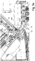
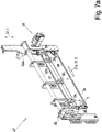
- One strand of meat 100 is processed, ie pressed and then cut into slices 101 , parallel to one another, essentially synchronously, on two lanes lying next to one another in the first transverse direction 11.1 .
- the longitudinal direction 10b the direction of passage through the cutting machine 1, on one of two parallel, side-by-side and separately drivable feed conveyors 14a , b, as best shown in Figure 2c recognizable, strands of meat to be cut delivered.
- the feed conveyors 14a , b have side walls in order to prevent the elongate strands of meat 100 extending thereon in the longitudinal direction 10b from falling down.
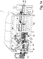
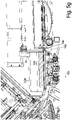
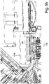
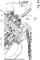
- the two strands of meat 100 are then each arranged in alignment in the longitudinal direction 10b in front of the front end of the respective feed conveyor 14a , b, pivotable rear U-part 2.2b - as in Figure 1a , b , c to see - inserted, whose in this pivoted position, the loading position, in the longitudinal direction 10 b extending U-shaped cross-section is open at the top.
- the respective U-part 2.2 b extending in the longitudinal direction 10 - depending on the operating position, the pressing direction 10 a or the direction of passage 10 b through the machine or a direction lying in between - is a component of one of two adjacent shaped tubes 2 , which in at least one of the Transverse directions 11.1, 11.2 consists of several mold parts that can be moved relative to one another.
- the shaped tube 2 In the longitudinal pressing direction 10a , the direction of feed of a strand of meat through a shaped tube 2, the shaped tube 2 consists of one in the direction of feed 10 a front front shaped pipe 2.1 and a rear shaped pipe 2.2 ( Figure 2b )
- the rear shaped tube 2.2 can even be changed by moving at least one of the shaped parts back and forth between a circumferentially closed state and a circumferentially open state:
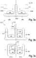
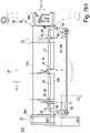
- a circumferentially closed state Like the cross-sections of the Figures 3a, b - which will be explained in more detail later - of the rear shaped tubes 2.2, in the open state and in the circumferentially closed state, consists - in the closed state according to Figure 3b
- right - each rear shaped tube 2.2 essentially consists of one of two adjacent, upwardly open U-parts 2.2 b, which have a common middle wall, and two exactly in the width of the cross-sectional openings according to Figure 3b , cross press stamps that fit on the right and can be inserted from above 2.2 a.
- each strand of meat 100 is pushed out over the front, lower end of its shaping tube 2 until its front, front end touches a stop plate 13 ( Fig. 2d , Figure 4a , b ) is present. Then by a knife 3 ( Figure 4c , 7 , 8th ), which is wider than the two adjacent shaping tubes 2, by lowering the rotating knife in the second transverse direction 11.2 immediately in front of the front end of the two shaping tubes 2 , a slice 101, 102 is separated from each of the two strands of meat 100 in the two shaping tubes 2 will.
- the distance set in the longitudinal pressing direction 10a between the stop plate 13 and the blade 3 determines the thickness of the disc 101, 102.
- the cut slices 101, 102 each fall onto one of two weighing stations 18 arranged next to one another, and are either weighed there individually, or - if the slices 101, 102 are to be combined into portions 110 - the weight achieved after each new slice of the building up and portion 110 remaining on the weighing station 18 .
- the slice or the created portion is then transferred from the weighing station 18, the upper side of which is constructed as a conveyor transporting in the throughput direction 10b , to a downstream discharge conveyor 22 and transported away, which are preferably also provided separately for each lane of the cutting machine next to one another .
- each shaped tube 2 is—as mentioned above—divided in the longitudinal pressing direction 10a into a front shaped tube 2.1 and a rear shaped tube 2.2.
- the front U-part 2.1 b as one of the front molded parts 2.1 a, b always remains unchanged in its position, while the front transverse press ram 2.1 a, also one of the front molded parts, moves relative thereto in the second transverse direction 11.2 can.
- the rear U-part 2.2b is pivoted downwards about a rear pivot axis 5 running in the first transverse direction 11.1 , so that the rear shaped tubes 2.2 are now in the fully open loading position, as described above.
- An intermediate plate 8 that can be moved in the plane perpendicular to the longitudinal pressing direction 10a is arranged between the rear shaped tube 2.2 and the front shaped tube 2.1 Figure 2d can be seen, and is preferably arranged at the rear end of the front U-part 2.1 .
- the width of the rear U-parts 2.2b of the rear shaped tubes 2.2 which are usually connected to one another via the common center wall, can be increased again and folded down into the loading position.
- the next two strands of meat 100 to be sliced can now be inserted with the help of the pusher 21 into the rear U-parts 2.2 b, which have been folded down into an aligned position with respect to the feed conveyors 14 a, b, in order to reduce the reloading time when changing to to reduce the next strands of meat 100 when slicing.
- the slice thickness d is set in a defined manner by setting the distance 9 between the stop plate 13 and the knife 3 while a slice 101 is being cut off.
- FIG. 4a , b , c shows a first design of a cutting unit 27 - in particular in figure 4 a - that for this the stop plate 13 in the axial direction 10a and/or in the first transverse direction in relation to the blade 3 and the blade plane 3", which is defined by the contact surface of the blade 3 facing the material to be cut, in which, with a blade only sharpened on the side facing away from it 3 the cutting edge 3a of the blade 3 is also located.
- the knife 3 also lifts after the cutting off of one pane 101 each, i.e. crossing the inner cross-section 7' of the at least one shaped tube 2, in the feed direction 10a in a lifting movement 28b from the front end face of the front shaped tube 2.1, on which it has moved contactingly or at a very close distance along to separate the discs 101 , and then or simultaneously with this lifting movement 28 b begins its return movement 28 c - toward the end thereof
- Figure 4c is shown - in the second transverse direction 11.2 against the cutting movement 28 a.
- the blade 3 --caused by an indicated lifting device 28 --performs a circular movement in the form of a rectangle or a lens shape.
- the stop plate 13 does not carry out either the axial lifting movement 28 b or the return movement 28 d of the blade 3 , but only its cutting movement 28 a and return movement 28 c, i.e. it always remains in the same axial position during the cutting process of a slice.
- the axial position of the cutting insert 13 is only occasionally changed between the cutting processes in order to change the thickness of the discs 101 to be produced.
- the cutting unit 27 is thus designed in such a way that during the cutting process the stop plate 13 is only fixedly coupled to the knife 3 in the second transverse direction 11.2 .
- the distance in this second transverse direction 11.2 between the knife axis 3' and the stop plate 13 is also adjustable, since the gap viewed in the feed direction 10a between the flight circle 3 * and the analogous concave front edge of the stop plate 13 facing the knife 3 - as in Figure 4d visible - should preferably also be adjustable on the cutting unit 27 , depending on the thickness of the slices 101 to be produced.
- the thickness of the pane in order to achieve a specific target weight and thus target volume of the panes 101 , their area, ie perpendicular to the thickness, must also be known and controllable.
- the serves this purpose Compression of the elastic strand of meat 100 in a forming tube 2 before cutting open the strand of meat 100 to a defined cross section: If the shaped tube 2, which is delimited both circumferentially by the shaped tube parts and in the longitudinal pressing direction 10a by the intermediate plate 8 on the one hand and the longitudinal pressing ram 4 on the other hand, has a defined inner free space 7 , and this is completely filled by the strand of meat 100 , the cross section of the strand of meat 100 is identical to the inner free cross section 7' of the forming tube 2, and thus the area of the slice 101, 102 to be severed and also the volume and thus the weight of the severed slice, provided the thickness is known and/or can be controlled, even if the pane deforms back after being cut off in terms of its contour.
- the strand of meat 100 is pressed both in the two transverse directions 11.1, 11.2 and in the longitudinal pressing direction 10a .
- the strand of meat 100 is initially in accordance with Figure 1a , b , c the rear U-part 2.2b of the rear molded part 2.2, which is folded down into the loading position, is inserted in the throughput direction 10b by means of the pusher 21 , as described above.
- the interior of the rear U-part 2. 2 b must have a greater width than the largest width that occurs of a still undeformed strand of meat 100.
- the rear two U-parts 2.2b have a common central wall, which serves as the fixed side wall facing the other rear shaped pipe 2.2 is integrally formed together with the respective bottom of the rear molded part 2.2 b as an angle part 2.2 b 1 .
- the two angle parts 2.2 b 1 form a one-piece design for both rear shaped tubes 2.2 together in a cross-section approximately inverted T-shaped T-part.
- the remaining inner free cross-section 7' is approximately rectangular with rounded corners, so that the elastic strand of meat 100 can also lie well into the corners, which is all the more possible the more the corners are rounded.
- the inner corners of the cross-sections of the U-parts 2.2 b are rounded and the transverse press rams 2.2 a have on their longitudinal edges of the free end face a forward-projecting, approximately triangular extension with a circular arc-shaped concave, towards the inner free cross-section 7 ' pointing, hypotenuse.
- each shaped tube 2 is movable in the first transverse direction 11.1 to the angle part or T-part 2.2 b 1 and is designed as a transverse pressing wall 2.2 b 2 and with its lower narrow side close along the top side of the horizontal leg of the respective angle part 2.2 b 1 against the middle wall can be moved towards or away from it.
- the transverse pressing wall 2.2 b 2 has moved outwards to the maximum distance from the middle wall, while still sitting on the upper side of the angle part 2.2 b 1 ( Figure 3a ).
- transverse press wall 2.2 b 2 is moved in the direction of the center wall ( Figure 3b , left) except for a defined final width of the interior of the U-part 2.2 b ( Figure 3b , to the right).
- the strand of meat 100 lying therein experiences a first transverse compression to a defined width in the first transverse direction 11.1.
- the position of this rear end is preferably determined by determining the end position of the pusher 21 - which is then available separately for the two tracks and actuates what needs to be - for the respective U-part 2.2 b at the end of the push-in process of the new strand of meat 100 and at the control is reported, so that the longitudinal press ram 4 only has to be withdrawn to just beyond this position in order to further reduce dead times.
- the longitudinal press ram 4 can easily be exchanged on the piston rod 12 for another longitudinal press ram 4 with a different cross section, depending on the thickness of the strands of meat 100 to be processed.
- the free inner cross-section 7' In order to facilitate the complete filling of the inner free space 7 of each shaped tube 2 during pressing with the material of the meat strand 100 , the free inner cross-section 7', despite being rectangular or trapezoidal in shape with two opposite inner surfaces running parallel to one another, has relatively strongly rounded inner corners: On the one-piece angle part 2.2 b 1 , this rounding can already be provided during manufacture. The other rounding is worked into the free lower, inward-pointing longitudinal edge of the transverse pressing wall 2.2 b 2 , in that a projection 17 protrudes inward from its inward-pointing side surface, which is in the form of a preferably right-angled triangle with a concave quarter-circle hypotenuse possesses.
- the same projections 17 are formed on the lower longitudinal edges of the transverse ram 2.2a .
- the described first transverse compression of the strand of meat 100 in the first transverse compression direction 11.1 can also be carried out directly in the rear U-part 2.2 b of the rear shaping tube 2.2 in a transverse compression trough immediately in front of the rear shaping tube 2.2 when it is in the loading position.
- 2 b can be formed by the feed conveyor 14 , so that only a fixed, stable middle wall and two on either side of it in the first transverse direction 11.1 towards and away from this transverse pressing walls are present, which press the strand of meat 100 in the first transverse pressing direction.
- the strand of meat 100 pressed in the first transverse pressing direction 11.1 is pushed into the U-part 2.2b of the rear shaped tube 2.2 , the width of the cross-section of the U-part then already corresponding to the target width.
- the U-part 2.2b of the shaped rear tube 2.2 can also be designed in one piece.
- transverse guides 23 can be seen under the bottom of the U-part 2.2 b, along which the transverse pressing walls 2.2 b 2 are displaced in the first transverse pressing direction 11.1 .
- an intermediate plate 8 which is movable thereon in the second transverse direction 11.2 to the mold tube 2 - either separately for each mold tube 2 or continuously over both mold tubes 2 in the first transverse direction 11.1 - which, after the rear U-part 2.2b has been folded up, is then located in the longitudinal pressing direction 10a between the front molded tube 2.1 and the rear molded tube 2.2 .
- This intermediate plate 8 can be moved back and forth between a closed position closing the inner cross section 7' of the shaped tube 2 and an open position releasing it.
- the intermediate plate 8 is initially still in the closed position, specifically as long as the strand of meat 100 now lying in the rear shaped tube 2.2 and pressed transversely in both transverse directions 11.1, 11.2 is then pressed by means of the longitudinal ram 4 in the longitudinal pressing direction 10 a, the intermediate plate 8 serves as a stop in the longitudinal pressing direction 10a. Since it is supported downstream by the front molded tube 2.1 , it can be made very thin.
- the longitudinal pressing i.e. forward movement of the longitudinal pressing ram 4 by means of the driven piston rod 12, takes place until a defined pressing force is reached, so that by determining the end position of the longitudinal pressing ram 4 by means of a position sensor - not shown - its distance from the intermediate plate 8 and thus now the The total volume of the strand of meat 100 is known and it can therefore also be calculated in advance how many slices of a defined volume, ie with a defined thickness, can be cut from it. Because if the actual end position of the longitudinal pressing ram cannot assume a previously expected target end position, at least the deviation from this in the form of the actual end position reached is known and can be taken into account in the calculation. This is because, within certain limits, the longitudinal pressing stamp, which can be designed in two parts in the second transverse direction, is also variable.
- the lengths of the completely pressed strands of meat 100 and thus also the number of identical slices 101 , 102 that can be obtained from them will differ for the two strands of meat 100 , and for example when one is cut open of the two strands of meat 100 leave the longitudinal area of its rear shaped tube 2.2 earlier.
- this U-part 2.2b can be pivoted downward earlier by means of the scissor linkage 19 .
- the longitudinal pressing ram 4 of the one of the two strands of meat 100 that was completely cut earlier can be moved back earlier into its retracted position.
- stop plates 13 are also designed separately and independently of one another and their distance - also to a common knife 3 -, i.e. with regard to the slice thickness achieved, can be adjusted independently of one another, on the two tracks of the cutting machine 1, i.e. from the two shaped tubes 2, disks 101, 102 of different thicknesses are produced.
- the intermediate plate 8 is moved in the transverse direction from the closed position into the open position by means of an intermediate plate drive.
- the resulting gap in the direction of advance 10a between the front shaped tube 2.1 and the rear shaped tube 2.2 can be closed by inserting a filler plate 8' according to FIG Figure 4a to c , which has the same axial thickness as the intermediate plate 8 , but such a large through-opening in the axial direction that, when the filling plate 8' is fully inserted, its inner peripheral contour is aligned with the inner peripheral contour of the shaped tube 2 .
- the longitudinal press ram 4 is moved further forward into the rear shaping tube 2.2 , and as a result the front end of the strand of meat 100 received therein is pushed forward into the front shaping tube 2.1 and through it until it rests against the stop plate 13.
- the front transverse ram 2.1a dips into its front U-part 2.1b to the same extent as the rear transverse ram 2.2a into its rear U-part 2.2b . Therefore, the front and rear transverse ram 2.1a and 2.2a can also be designed in one piece with each other and moved for each shaped tube 2 , even over both shaped tubes 2 as a common transverse ram unit, provided that the same longitudinal Press ram 4, ie with at least the same extent in the second transverse direction 11.2 , preferably the same front surface, is used.
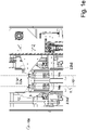
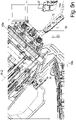
- Figure 1b shows a vertical section lying in the longitudinal direction 10 b along the line B - B of figure 1 i.e.
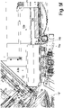
- Figure 1e shows - viewed in the direction of advance 10 a - a cross section along the line E - E of figure 1 b.
- the cutting blade 3 which is circular in this viewing direction, can be seen, as well as the front shaped tube 2.1 with a view in its direction of extension, ie in the longitudinal pressing direction 10a , and in front Above all, the front transverse press ram 2.1 a, which in this case runs over the entire length of the shaped tube 2 and is therefore also the rear transverse press ram 2.2 a.
- the stop plate 13 can be adjusted in its axial distance from the blade 3 in the longitudinal pressing direction 10a , it being evident that the stop plate 13 and the blade 3 preferably do not overlap when viewed in the longitudinal pressing direction 10a .
- the intermediate plate 8 can again be seen, which in this case, including its drive, is attached to the rear end face of the front molded tube 2.1 .
- stop element that closes the inner free cross section of the rear U-part 2.2b and is also movable in the transverse direction, for example in the form of an end plate as a stop when a strand of meat is pushed in 100 in the loading position.
- the intermediate plate 8 is then placed in the inner free cross-section 7' is moved into the closing position and in the process pushes the end plate, which is movable in the same plane and direction and is preferably of the same thickness, out of the free inner cross-section 7' .
- Figure 2d also shows the adjustment device 26 for adjusting the distance 9 of the stop plate 13 to the knife 3 in the longitudinal pressing direction 10a .
- the figures 5 a - n show different operating states of the cutting machine in a slightly perspective view with a vertical longitudinal section along the line B - B of the figure 1 i.e.
- the cut is in the direction of the Figure 1b in the front processing track, for example the feed conveyor 14a , but close to the rear end in this viewing direction.
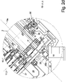
- figure 5 a can be seen with regard to the shaped tube 2 , the axial area of the front shaped tube 2.1 and the rear shaped tube 2.2 , over their common length of the transverse ram 2.1 + 2. a and which is acted upon by a plurality of piston rods 12.1', 12.2' in the second transverse direction 11.2 .
- One of the piston rods 12.1' is located in the area of the front molded tube 2.1.
- the slices separated by the blade 3 at the front end of the forming tube 2 fall onto a weighing station 18 which transfers the slices—or portions—to a first discharge conveyor 22 after weighing.
- the Weighing station 18 is according to the Figure 1b not connected to the frame of the rest of the slicer but rests itself on the ground to minimize transmission of vibrations from the slicer to the weighing station 18 .
- Figure 5a shows together with the detail enlargement in Figure 5b
- the start of the slicing process (described below only for the shaped tube 2 shown in section and the corresponding processing track; the same process can take place parallel to this on the processing track behind it, with the knife 3 always cutting off a slice from both shaped tubes at the same time ), in which the strand of meat 100 is pressed forwards by the longitudinal press ram 4 to beyond the front end of the shaped tube 2 until it rests against the stop plate 13.
- the knife 3 is still completely above the or the two adjacent shaped tubes 2.
- the knife 3 After the knife 3 has been lowered, the knife 3 covers the free inner cross-section of the two - forming tubes 2 and the severed slices - of which in Figure 5c only the pane 101 cut off on the rear processing track can be seen - fall onto the first discharge conveyor 22 and can be transported away and processed further, as in Figure 5c shown in a state a few discs later. Then the longitudinal press ram 4 pushes the strand 100 further forward until it rests against the stop plate 13 for cutting off the next pane
- Figure 5d shows the state when the strand of meat 100 has been cut open to such an extent that it is only in the axial area of the front shaping tube 2.1 and the longitudinal pressing ram 4 is already in the shaping tube 2.1 .
- the rear U-part 2. 2 b of the rear shaped tube 2.2 pivots by a better in figure 1 c visible pivot axis 5 with its rear end down - while the remainder of the strand of meat 100 located in the front shaping tube 2.1 is further cut open - until according to Figure 5e the rear U-part 2.2b is aligned with the top of the feed conveyor 14a , b with regard to the underside of its interior.
- transverse compression walls 2.2 b 2 are relative to the middle wall of the angle part 2.2 b 1 (see Figure 3a ) to the outside, so that the in Figure 5f on the feed conveyors 14 a, b can be moved up in the direction of passage 10 b to immediately in front of the rear end of the rear U-part 2.2 b and in this direction by means of the pusher 21 with its two prongs acting on the rear ends of the meat strands 100 can be inserted into the rear U-parts 2.2b of the two shaped tubes 2 , as in Figure 5g shown.
- the longitudinal compression can be carried out by moving the longitudinal compression ram 4 forward in the longitudinal compression direction 10 a and subsequent cutting out - as described above - the new strand of meat 100 can be started.
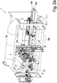
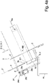
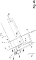
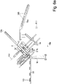
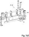
- a second embodiment of the cutting machine 1 compared to Figures 1 - 5 show the Figures 6a , b with the two adjacent - this design can also process two strands of meat 100 simultaneously on two adjacent lanes - shaped tubes 2 in figure 6 a in loading position and in Figure 6b in the cutting position.
- This second design differs from that of the following Figure 1 to 5 :
- the rear U-parts 2.2 b in relation to the rear transverse press rams 2.2 a or the transverse press rams 2.1+2.a running over the entire axial length of the shaped tubes, these—viewed in the first transverse direction 11.1— moved apart or against each other, with the two parts maintaining their parallel position to one another, in that - again with the aid of a scissor linkage 19 - the rear U-part 2.2 b is objected to by the latter, while maintaining the parallel position to the rest of the shaped tube 2 , i.e. not by pivoting about a pivot axis.
- each rear U-part 2.2 b also runs in the in figure 6 a shown loading position inclined forwards downwards with the result that a strand of meat 100 transported to the rear end by means of the feed conveyor 14 a, b and finally protruding beyond the front end of the feed conveyor 14 a, b is tipped into the U-part 2.2 b slides in and down in it, so that a separate insert can be dispensed with.
- the feed conveyor 14a , b must bring the strands of meat 100 to the height of the rear end of the rear U-part 2.2b in the loading position and can not only be horizontal at its front end to make it easier to fall in, but also slightly inclined downwards be trained.
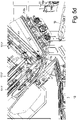
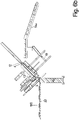
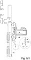
- FIGS 7a to 7c1 show a second design of a cutting unit 27, the basic movement in the Figures 8a , b is explained.
- this cutting unit 27 has a bar-shaped knife 3, the bar-shaped cross-section being so thin that it is probably better to speak of a strip-shaped knife 3 .
- the cutting unit 27 is made up of a base body 32, which is moved downwards in the first knife transverse direction 31.1 to cut off a slice so far that the cutting edge 3a of the knife 3 fastened therein, which is straight in this case, completely runs through the cross section of a strand of meat 100 . as in figure 7 c 1 indicated.
- the base body 32 consists of two spaced-apart side supports 32a , which are spaced parallel to one another and run transversely to the direction in which the side supports 32a extend in the first knife transverse direction 31.1 Have cross-section, are added to a frame-shaped base body 32 .
- the knife unit 33 in which the knife 3 is located, is fastened to the lower of the two spacer rods 32b :
- the blade unit 33 comprises three support struts 35 spaced apart in the longitudinal direction of the lower spacer bar 32b, which are pivotably mounted on this spacer bar 32b and are firmly connected at their free end to a support plate 34 that extends over all three support struts 35 .
- the support plate 34 thus extends in the same direction as the spacer rod 32b , ie in the second knife transverse direction 31.2.
- the strip-shaped knife 3 is arranged in the feed direction 10a directly behind the back of the support plate 34 in such a way that its cutting edge 3a , which is arranged on the lower edge of the knife 3 , protrudes beyond the support edge 34a of the support plate 34 , but relative to this approximately in the second knife transverse direction 31.2, the direction of the knife edge 3a , is movable.
- the knife 4 lies with its front surface on a piece incorporated into the back of the support plate 34 shoulder, the shoulder being slanted to the front of the support plate 34.
- the cross section of the knife 3 is oblique to the cross section of the support plate 34, and the cutting edge 3a of the knife 3 may even protrude somewhat beyond the front surface of the support plate 34 against the feed direction .
- the blade 3 is also beveled on its front surface to form a cutting edge 3a, with this beveling of the front surface of the blade 3 defining the blade plane 3 " which, as already mentioned, may be slightly opposite to the feed direction 10a in the direction of the shaped tube in front of the Front surface of the support plate 34 may be.
- the blade 3 is fastened with each of its ends to the free end of a respective drive lever 36 , which is designed as a two-armed drive lever and in its middle region to one of the two blade plates in the main direction of extension 34, the second blade Transverse direction 31.2, opposite ends of the support plate 34 are pivotable about a lever axis 36' running transversely to the blade plane 3" and thus also to the support plate plane 34' .
- the other two free ends of the drive levers 36 are connected to one another via a coupling rod 37 , so that the oscillating back and forth movement of one driven swivel lever 36 caused by a blade motor 38 can be carried out not only via the blade 3 itself, but also via the coupling rod 37 is transferred to the other pivot lever 36 , and thereby the knife 3 can be made less stable.
- pivoting levers 36 could also be designed as single-armed levers, and then the point of action of the pivoting lever driven by the blade motor 38 and operatively connected to the driven pivoting lever 36 is between the pivoting axis 36' and the attachment point of the knife 3 would have to act on this pivoting lever 36 .
- the knife 3 and its cutting edge 3a do not perform an exactly linear oscillating movement in the direction of its straight cutting edge 34a , but rather a slightly arcuate movement, the radius of curvature of which corresponds to the distance between the lever axis 36' and the Attachment end of the knife 3 corresponds to each of the pivoting levers 36 .
- an oscillating back and forth movement is referred to.
- the entire cutter unit 33 - consisting of support struts 35, support plate 34, cutter 3, drive levers 36 - can also be pivoted about the lower, round cross-section distance that serves as the pivot axis 28 -Rod 32 b are pivoted back and forth, namely from a cutting position to a lifting position.
- figure 7 c 1 shows the cutting position in which the blade plane 3" is parallel to the first blade transverse direction 31.1, in which the base body 32 is moved along the frame of the machine to cut off the slices.
- figure 7 c 2 shows the lift-off position in which the knife unit 33 can be pivoted about the pivot axis 28', ie about the lower spacer rod 32b , somewhat in the feed direction 10a , ie away from the strand of meat.
- the figures 7 d 1 and 7 d 2 show a design that differs from that of figures 7 c 1 , 2 differs only slightly.
- the motor 38 is not arranged protruding forwards on the base body 27 , but runs parallel to the frame-shaped base body 27 on its side.
- a connecting rod 41 Via a connecting rod 41 , it drives the knife 3' directly in an oscillating manner along its direction of extension, the knife being operatively connected to a carriage 39 which is guided in a guide 40 running in the direction of extension of the knife 3' .
- FIGS. 8a , b which are based on the illustrations in FIG Figures 4a to c are ajar and have the same line of sight:
- figure 8 a shows the state in which, when a slice is cut off by means of the cutting movement 28a in the first knife transverse direction 31.1 and the superimposed back and forth movement of the cutting edge 3a in the second knife transverse direction 31.2 , the knife 3 - which is in relation to the Cutting unit 27 in the cutting position according to figure 7 c 1 - the disc 101 has just completely separated.
- the Figure 8b shows the state in which, after a slice 101 has been completely severed, the measuring unit 33 with the knife 3 has been pivoted into the lifting position, thereby pushing the severed slice 101 away from the strand of meat 100 and thereby facilitating the dropping onto the weighing station 18 , but above all Immediately, so even before the return movement 28 c has begun in the first cross-knife direction 31.1 , the meat strand 100 can already be pushed forward, which is also the goal of the knife movements 28 a to d in the Figures 4a to c was.
- the entire cutting unit 33 performs the pivoting movement , but the lifting off the end face of the strand of meat 100 is correspondingly less than that of the cutting edge 3a , corresponding to the smaller distance from the pivot axis 28'.
Description
Die Erfindung betrifft das Aufschneiden eines elastischen Stranges wie etwa eines Fleischstranges in, insbesondere gewichtsgenaue, Scheiben.The invention relates to the cutting of an elastic strand, such as a strand of meat, into slices, particularly slices of precise weight.
Die Herstellung von gewichtsgenauen Scheiben oder Portionen aus einem elastischen Strangmaterial ist relativ problemlos möglich, wenn dieses Strangmaterial über seine Länge überall den gleichen Querschnitt besitzt und aus einem homogenen, überall gleich einfach zu durchtrennenden, Material besteht, wie etwa Wurst oder Käse.The production of weight-accurate slices or portions from an elastic strand material is relatively easy if this strand material has the same cross-section throughout its length and consists of a homogeneous material such as sausage or cheese that can be cut through everywhere with the same ease.
Hierfür sind so genannte Slicer bekannt, die meist mit einem runden oder spiralförmigen, rotierenden Messer, welches quer zum Strang vor- und zurückgefahren werden kann, jeweils eine Scheibe abschneiden, während der dabei meist frei liegende Strang kontinuierlich vorwärts gefahren wird.So-called slicers are known for this purpose, which usually cut off a slice with a round or spiral-shaped, rotating blade that can be moved back and forth across the strand, while the strand that is usually exposed is continuously advanced.
Ein Fleischstrang, z.B. Roastbeef, hat diese Eigenschaften jedoch nicht, denn jedes Stück besitzt eine andere Gestaltung und darüber hinaus einen sich über die Länge ändernden Querschnitt und besteht aus Materialien unterschiedlicher Konsistenz, Härte und Elastizität, beispielsweise aus den Fettanteilen, dem reinen Muskelstrang, der umgebenden Silberhaut und gegebenenfalls auch noch Knochen wie bei einem Kotelett-Strang, die sich mechanisch sehr unterschiedlich verhalten.However, a strand of meat, e.g. roast beef, does not have these properties, because each piece has a different shape and, in addition, a cross-section that changes over the length and consists of materials of different consistency, hardness and elasticity, for example the fat content, the pure muscle strand, the surrounding silver skin and possibly also bones like in a chop strand, which behave mechanically very differently.
In diesem Zusammenhang ist es bereits bekannt, einen Lachs zunächst so zu verformen, dass dieser zumindest an dem Ende, an dem die nächste Scheibe abgeschnitten wird, vorzugsweise über die gesamte Länge, einen definierten, bekannten Querschnitt besitzt, zumindest im Zeitpunkt des Abschneidens der Scheibe. Dann kann eine Relation zwischen der einstellbaren Dicke der Scheibe und dem Gewicht der Scheibe hergestellt werden, wenn auch nicht hundertprozentig, da sich von einer Scheibe zur nächsten die Zusammensetzung des Fleisches , dessen Komponenten unterschiedliche spezifische Gewichte aufweisen, bereits ändern kann.In this context, it is already known to first deform a salmon in such a way that it has a defined, known cross-section at least at the end at which the next slice is cut off, preferably over the entire length, at least at the time the slice is cut off . Then a relation between the adjustable thickness of the slice and the weight of the slice can be established, albeit not 100%, since the composition of the meat, whose components have different specific weights, can already change from one slice to the next.
Um diese Verformung zu erreichen, wird der - in der Regel leicht angefrorene - Lachs zunächst in ein Formrohr eingesteckt, und in axialer Richtung mittels eines Längs-Pressstempels gegen einen Anschlag gepresst, sodass sich der Lachs in seinem Querschnitt so aufweitet, dass er den gesamten inneren Freiraum des Formrohres ausfüllt.In order to achieve this deformation, the - usually slightly frozen - salmon is first inserted into a shaped tube and pressed against a stop in the axial direction by means of a longitudinal press punch, so that the salmon expands in its cross-section so that it covers the entire fills the inner space of the molded tube.
In diesem Zusammenhang ist aus der
Dabei können Formrohre unterschiedlichen Querschnittes benutzt werden, je nach Abmessungen des Lachses, und der Querschnitt des Formrohres kann nach Einlegen des Lachses zusätzlich verändert werden, beispielsweise indem zwei gegenüberliegende Seitenwände des Formrohres aufeinander zu bewegt werden, und damit auch eine Querverpressung des Lachses bewirkt wird, was die Struktur des Fleisches schont.Shaped tubes with different cross-sections can be used, depending on the dimensions of the salmon, and the cross-section of the shaped tube can also be changed after the salmon has been put in, for example by moving two opposite side walls of the shaped tube towards one another, thus causing the salmon to be pressed transversely. which protects the structure of the meat.
Bei derartigen Schneidemaschinen kann der Lachs nur in das Formrohr eingeschoben werden, nachdem der Längspress-Stempel oder der Querpressstempel aus dem Formrohr entfernt wurde und die Beladeöffnung, meist die hintere Öffnung des Formrohres, frei zugänglich ist.With such cutting machines, the salmon can only be pushed into the forming tube after the longitudinal press stamp or the transverse press stamp has been removed from the shaped tube and the loading opening, usually the rear opening of the shaped tube, is freely accessible.
Dies bewirkt relativ lange Tot-Zeiten zwischen den Aufschneide-Phasen und erforderte bisher ein Beladen von Hand.This results in relatively long dead times between the slicing phases and previously required manual loading.
Für die Integration einer solchen Schneidemaschine in eine Verarbeitungs-Linie - meist bestehend aus einem Froster, einer oder mehreren parallel arbeitenden Schneidemaschinen, einer Waage, einem Portionierer/Einleger zum Einlegen der Portionen/Scheiben in eine Schale und gegebenenfalls einer Siegel-Maschine zum dichten Versiegeln der Schalen - ist dies jedoch hinderlich, da hierfür entweder ein Mitarbeiter zum Beladen von ein bis drei Schneidemaschinen benötigt wird oder ein hoher Automatisierungsaufwand betrieben werden muss, um diese Mitarbeiter einzusparen.For the integration of such a cutting machine in a processing line - usually consisting of a freezer, one or more cutting machines working in parallel, a scale, a scoop/insert for placing the portions/slices in a tray and, if necessary, a sealing machine for tight sealing of the trays - this is a hindrance, however, since either one employee is required to load one to three cutting machines or a high degree of automation is required in order to save these employees.
Zusätzlich müssen die einzelnen Formrohre, also Fleischstränge, möglichst individuell handhabbar sein, da zum Beispiel bei einer Oberschale nach Entfernen des Qualitäts-Anschnittes Schnitzel geschnitten werden können,In addition, the individual shaped tubes, i.e. strands of meat, must be able to be handled individually as possible, since, for example, in the case of an upper shell, after removing the quality cut, schnitzels can be cut.
Dagegen können aus einem Schweinerücken nach Entfernen des Qualitäts-Anschnittes Minuten-Steaks geschnitten werden, und das Reststück aus rotem Fleisch als Braten verwendet werden.On the other hand, minute steaks can be cut from a pork loin after removing the quality cut, and the remainder of red meat can be used as a roast.
Es ist daher die Aufgabe gemäß der Erfindung, eine Schneidemaschine sowie ein Verfahren zum Aufschneiden zur Verfügung zu stellen, welches trotz einfachem Aufbau und Ablauf geringe Totzeiten und damit einen hohen Durchsatz bei dennoch sehr gewichtsgenau erzielbaren Scheiben und Portionen ermöglicht.It is therefore the object of the invention to provide a slicing machine and a method for slicing which, despite a simple structure and process, enables short dead times and thus a high throughput with slices and portions that can still be achieved with very high weight accuracy.
Diese Aufgabe wird durch die Merkmale der Ansprüche 1 und 12 gelöst. Vorteilhafte Ausführungsformen ergeben sich aus den Unteransprüchen.This object is solved by the features of
Für die Zwecke der vorliegenden Erfindung wird im Folgenden ausschließlich von Fleischsträngen gesprochen, ohne die Erfindung auf diese spezielle Art eines Stranges aus elastischem Material zu beschränken.For the purposes of the present invention, only meat strands are discussed below without restricting the invention to this special type of strand made of elastic material.
Hinsichtlich des Verfahrens wird diese Aufgabe durch folgenden Verfahrensablauf gelöst:
Der aufzuschneidende Strang, zum Beispiel ein Fleischstrang, wird in einem in Längsrichtung verlaufenden, Formrohr angeordnet, sodass seine größte Erstreckung, seine Längsrichtung, mit der Längsrichtung des Formrohres übereinstimmt. Anschließend wird der Strang mit Hilfe des Formrohres in mindestens einer Querrichtung, der sogenannten zweiten Querrichtung, zusammengepresst, sodass dieser einen definierten, im Wesentlichen über die gesamte Länge konstanten, Querschnitt erhält.With regard to the process, this task is solved by the following process sequence:
The strand to be cut, for example a strand of meat, is arranged in a shaped tube running in the longitudinal direction, so that its greatest extent, its longitudinal direction, corresponds to the longitudinal direction of the shaped tube. The strand is then compressed in at least one transverse direction, the so-called second transverse direction, with the aid of the shaped tube, so that it has a defined cross-section that is essentially constant over the entire length.
Der so quer-verpresste Strang wird in diesem quer-verpressten Zustand vorher, gleichzeitig oder anschließend im Formrohr in Längsrichtung, insbesondere mittels eines Längspressstempels, zunächst gegen einen Anschlag längs-verpresst und danach vorwärts geschoben über das vordere sogenannte Schneidende des Formrohres hinaus, sodass vor dem Schneidende des Formrohres von dem Strang jeweils eine Scheibe abgetrennt werden kann.In this cross-pressed state, the strand that has been cross-pressed in this way is previously, simultaneously or subsequently in the longitudinal direction in the shaped tube, in particular by means of a longitudinal press ram, first longitudinally pressed against a stop and then pushed forward beyond the front so-called cutting end of the shaped tube, so that a slice can be separated from the strand at the cutting end of the shaped tube.
Das Verpressen dient dazu, dass der Strang den freien Querschnitt des Formrohres vollständig ausfüllt und damit die Scheiben eine definierte Fläche quer zu ihrer Längsrichtung besitzen.The pressing serves to ensure that the strand completely fills the free cross-section of the shaped tube and that the discs therefore have a defined surface transverse to their longitudinal direction.
Das Abtrennen je einer Scheibe kann durch ein- und dasselbe Messer und im gleichen Arbeitsgang über alle Formrohre und damit Fleischstränge erfolgen. Das Messer wird zum Abtrennen der Scheiben vorzugsweise in Querrichtung, insbesondere der zweiten Querrichtung, bei jedem Schnitt vor und zurück bewegt.One slice can be cut off with one and the same knife and in the same operation over all the shaped tubes and thus meat strands. In order to cut off the slices, the knife is preferably moved back and forth in the transverse direction, in particular the second transverse direction, with each cut.
Zusätzlich zu dem Querverpressen in der zweiten Querrichtung kann, insbesondere vorher, ein Querverpressen in einer ersten, vorzugsweise auf der zweiten Querrichtung senkrecht stehenden, Querrichtung erfolgen, entweder bereits im Formrohr, insbesondere vor dem Schließen des umfänglich geschlossenen Formrohres oder noch vor dem einbringen in das Formrohr.In addition to the transverse pressing in the second transverse direction, transverse pressing can, in particular beforehand, take place in a first transverse direction, preferably perpendicular to the second transverse direction, either already in the mold tube, in particular before the closed mold tube is closed or before it is introduced into the molded tube.
Sowohl die bisher beschriebene als auch die nachfolgend beschriebene Vorgehensweise kann auch in mehreren nebeneinander, insbesondere parallel zueinander, verlaufenden Formrohren durchgeführt werden, in denen jeweils ein Strang eingebracht und bearbeitet wird. Dabei kann das Längs- und/oder Querverpressen in den einzelnen Formrohren unabhängig voneinander durchgeführt werden. Insbesondere wird das Abtrennen von Scheiben von den einzelnen Strängen durch ein und dasselbe Messer mittels ein und derselben Schnittbewegung über mehrere, insbesondere alte, Formrohre hinweg vollzogen.Both the previously described procedure and the procedure described below can also be carried out in a plurality of shaped tubes running next to one another, in particular parallel to one another, in each of which a strand is introduced and processed. In this case, the longitudinal and/or transverse pressing in the individual shaped tubes can be carried out independently of one another. In particular, slices are separated from the individual strands by one and the same knife by means of one and the same cutting movement over several, in particular old, shaped tubes.
Beim Abtrennen der Scheiben wird das Messer - beispielsweise ein rotierendes kreisscheibenförmiges oder sichelförmiges Messer oder ein oszillierendes, balkenförmiges oder streifenförmiges Messer oder ein umlaufendes endloses bandförmiges Messer - hinsichtlich seiner Drehzahl und/oder der Geschwindigkeit seiner Querbewegung so gesteuert, dass angepasst auf das zu schneidende Material der erfolgende Schnitt in dem gewünschten Maß ein sogenannter ziehender Schnitt ist, also ein bestimmter Punkt der Schneide sich in Umfangsrichtung mit einer Geschwindigkeit bewegt, die um einen vorgegebenen Faktor grösser ist als die Geschwindigkeit in Querrichtung.When separating the slices, the blade - for example a rotating disk-shaped or sickle-shaped blade or an oscillating, bar-shaped or strip-shaped blade or a revolving endless belt-shaped blade - is controlled with regard to its speed and/or the speed of its transverse movement in such a way that it is adapted to the material to be cut the cut to the desired extent is a so-called pulling cut, i.e. a certain point of the Blade moves in the circumferential direction at a speed that is greater than the speed in the transverse direction by a specified factor.
Das Quer-Verpressen der Fleischstränge in der ersten Querrichtung erfolgt vorzugsweise bis auf ein vorgegebenes, festes Maß, welches vorzugsweise für alle, vorzugsweise zwei, parallel liegende Formrohre und darin eingelegten Fleischstränge jeweils das gleiche Maß ist. Da das Quer-Verpressen in der ersten Querrichtung in aller Regel erfolgt, bevor das Quer-Verpressen in der zweiten Querrichtung durchgeführt wird, wird dieses Quer-Verpressen in der ersten Querrichtung im Folgenden weiterhin als Quer-Verpressen bezeichnet, de facto wird dabei jedoch lediglich der freie innere Querschnitt des Formrohres in dieser ersten Querrichtung auf eine bestimmte Breite eingestellt, und der darin liegende Fleischstrang nur wenig in dieser Richtung verpresst, beispielsweise bei einem länglichen Querschnitt nur etwas um seine Längsachse gedreht.The transverse pressing of the strands of meat in the first transverse direction preferably takes place up to a predetermined, fixed dimension, which is preferably the same dimension for all, preferably two, parallel shaped tubes and strands of meat inserted therein. Since the transverse pressing in the first transverse direction usually takes place before the transverse pressing in the second transverse direction is carried out, this transverse pressing in the first transverse direction will continue to be referred to as transverse pressing in the following, but de facto only the free inner cross-section of the shaped tube is set to a certain width in this first transverse direction, and the strand of meat lying therein is pressed only slightly in this direction, for example rotated only slightly about its longitudinal axis in the case of an elongated cross-section.
Dadurch kann das Quer-Verpressen in der zweiten Querrichtung - die vorzugsweise auf der ersten Querrichtung lotrecht steht und vorzugsweise beide lotrecht zur Längsrichtung stehen - mit einem Quer-Pressstempel einer bestimmten, nicht veränderbaren, Breite entsprechend dem Endmaß beim Quer-Verpressen in der ersten Querrichtung, erfolgen, vorzugsweise für die einzelnen Fleischstränge unabhängig voneinander hinsichtlich des Maßes der Quer-Verpressung in dieser zweiten Querrichtung.As a result, the transverse pressing in the second transverse direction - which is preferably perpendicular to the first transverse direction and preferably both perpendicular to the longitudinal direction - can be carried out with a transverse pressing ram of a specific, non-changeable width corresponding to the final dimension during transverse pressing in the first transverse direction , take place, preferably for the individual strands of meat independently of one another with regard to the extent of the transverse compression in this second transverse direction.
Das Vorwärtsschieben des verpressten wenigstens einen Stranges kann synchron oder unabhängig voneinander erfolgen, und somit können in demselben Arbeitsgang bei unterschiedlich weit vorgeschobenen Fleischsträngen auch unterschiedlich dicke Scheiben und wegen der individuell einstellbaren Querverpressung zumindest in der zweiten Querrichtung auch Scheiben mit unterschiedlichem Querschnitt und damit Größe in einem Arbeitsgang abgetrennt werden.The pressed at least one strand can be pushed forward synchronously or independently of one another, and thus slices of different thicknesses and, because of the individually adjustable transverse compression, at least in the second transverse direction, slices with different cross-sections and thus sizes can also be produced in the same operation with meat strands pushed forward by different distances Operation to be separated.
Der Strang wird in Längsrichtung vorzugsweise gegen ein jeweils vor dem vorderen Ende des Formrohres angeordnetes Anschlagelement, insbesondere eine Anschlagplatte, gedrückt, welche vorzugsweise für jedes Formrohr unabhängig voneinander in ihrem axialen Abstand zu der axialen Schneidposition des Messers eingestellt werden kann entsprechend der gewünschten Dicke der abzutrennenden Scheibe. Da sich ja das Messer beim Schneiden entweder Anlage oder in einem fixen, sehr kleinen, axialen Abstand zum vorderen Schneidende des Formrohres befindet, wird damit das Anschlagelement in einem bestimmten axialen Abstand zum vorderen Schneidende des Formrohres eingestellt.In the longitudinal direction, the strand is preferably pressed against a stop element arranged in front of the front end of the shaped tube, in particular a stop plate, which can preferably be adjusted independently for each shaped tube in terms of its axial distance from the axial cutting position of the blade according to the desired thickness of the material to be separated Disc. Since the blade is either in contact with or at a fixed, very small, axial distance from the front cutting end of the shaped tube when cutting, the stop element is thus set at a certain axial distance from the front cutting end of the shaped tube.
Eine Maßnahme zum Reduzieren der Totzeiten besteht darin, dass sich das Messer unmittelbar nach dem Abtrennen der vordersten Scheibe noch vor oder spätestens während des Zurückfahrens in Querrichtung axial, also in Vorschubrichtung, vorwärtsbewegt, insbesondere etwa um die Dicke einer Scheibe.One measure to reduce the dead times is that the knife moves forwards in the transverse direction, i.e. in the feed direction, immediately after cutting off the foremost slice, before or at the latest during the reverse movement, in particular by about the thickness of a slice.
Dies bewirkt, dass das Vorwärtsschieben des Fleischstranges über das vordere Ende des Formrohres hinaus bis zur Anschlagplatte nicht erst dann erfolgen kann, wenn das Messer den Querschnittsbereich des inneren Freiraumes des Formrohres vollständig verlassen hat, sondern bereits vorher beginnen kann, was die Zeitspanne zwischen zwei aufeinanderfolgenden Schnitten deutlich verringert und damit die Effizienz der Maschine steigert.This means that the strand of meat can be pushed forward beyond the front end of the shaping tube to the stop plate not only when the knife has completely left the cross-sectional area of the inner free space of the shaping tube, but can begin before that, which is the time interval between two consecutive Cuts are significantly reduced, thereby increasing the efficiency of the machine.
Natürlich muss danach, also wenn das Messer in Querrichtung den Querschnittsbereich des Formrohres ganz verlassen hat, das Messer in axialer Richtung entgegen der Vorschubrichtung wieder in seine axiale Schneidposition zurückverfahren werden, so dass das Messer in der Seitenansicht auf die Längsrichtung einerseits und die zweite Querrichtung, die Bewegungsrichtung des Messers andererseits, bei jedem Schnitt einen beispielsweise rechteckförmigen oder trapezförmigen Weg beschreibt.Of course, after that, i.e. when the knife has completely left the cross-sectional area of the shaped tube in the transverse direction, the knife must be moved back into its axial cutting position in the axial direction counter to the feed direction, so that the knife in the side view is in the longitudinal direction on the one hand and the second transverse direction, the direction of movement of the knife, on the other hand, describes, for example, a rectangular or trapezoidal path with each cut.
Hinsichtlich der Bewegung in der Querrichtung, in der sich das Messer bewegt, ist die Anschlagplatte mit dem Messer fest verbunden, lediglich deren axialer Abstand und/oder deren Abstand in der anderen Querrichtung kann verändert werden.With regard to the movement in the transverse direction, in which the blade moves, the stop plate is firmly connected to the blade, only its axial spacing and/or its spacing in the other transverse direction can be changed.
In Vorschubrichtung betrachtet überlappen die Anschlagplatte und das Messer - bei einem rotierenden nicht-kreisscheibenförmigen Messer der Flugkreis des Messers - vorzugsweise nicht miteinander, sondern dazwischen besteht ein schmaler Spalt.Viewed in the direction of feed, the stop plate and the knife—in the case of a rotating knife that is not in the shape of a circular disk, the cutting circle of the knife—preferably do not overlap with one another, but there is a narrow gap between them.
Eine erfindungsgemäß wichtigere andere Maßnahme zum Verringern der Totzeiten besteht darin, dass das Formrohr in seiner Längsrichtung zweiteilig ausgebildet ist und aus einem am vorderen Schneidende endenden FrontFormrohr und einem sich daran nach hinten anschließenden Heck-Formrohr besteht.Another measure to reduce dead times that is more important according to the invention is that the shaped tube is designed in two parts in its longitudinal direction and consists of a front shaped tube ending at the front cutting end and a rear shaped tube adjoining it to the rear.
Dadurch ist es möglich, dass das Heck-Formrohr bereits mit einem neuen aufzuschneidenden Strang beladen wird, während der Rest des alten noch aufzuschneiden Stranges sich nur noch im Front-Formrohr befindet und dort weiter vorwärtsgeschoben wird, insbesondere mithilfe des Längspressstempels, und vollständig aufgeschnitten wird.This makes it possible for the rear shaped tube to already be loaded with a new strand to be cut while the rest of the old strand still to be cut is only in the front shaped tube and is pushed further forward there, in particular with the help of the longitudinal press ram, and is completely cut open .
Hierfür kann vorzugsweise das Heck-Formrohr von einer umfänglich geschlossenen in eine umfänglich geöffnete Ladestellung verbracht werden.For this purpose, the rear shaped tube can preferably be brought from a peripherally closed to a peripherally open loading position.
Zwischen Front-Formrohr und Heck-Formrohr diesen ist vorzugsweise eine Zwischenplatte in einer Querrichtung, insbesondere der zweiten Querrichtung, ein- und ausgefahrbar. Wie Quer-Verpressung im Front-Formrohr kann abhängig von der Quer-Verpressung im dahinter angeordneten HeckFormrohr durchgeführt werden.Between the front molded tube and the rear molded tube, an intermediate plate can preferably be moved in and out in a transverse direction, in particular the second transverse direction. How transverse compression in the front shaped pipe can be carried out depending on the transverse compression in the rear shaped pipe arranged behind it.
In der umfänglich geschlossenen, verpressenden Stellung des Formrohres werden die Querschnitte von Front-Formrohr und Heck-Formrohr natürlich identisch eingestellt, da sich ja der gleiche Fleischstrang und den Querschnitt vollständig ausfüllend, durch beide hindurch bewegen soll.In the circumferentially closed, pressing position of the shaping tube, the cross sections of the front shaping tube and rear shaping tube are of course set identically, since the same strand of meat and completely filling the cross section should move through both.
Vorzugsweise wird im Front-Formrohr keine Quer-Verpressung in beiden Querrichtungen, sondern nur in der zweiten Querrichtung durchgeführt.Preferably, no transverse compression is carried out in the two transverse directions in the front molded tube, but rather only in the second transverse direction.
Front-Formrohr und Heck-Formrohr können hinsichtlich des Zeitpunktes und der Stärke der Quer-Verpressung, - zumindest in einer Querrichtung, vorzugsweise in beiden Querrichtungen - unabhängig voneinander betätigt werden.The front molded tube and the rear molded tube can be actuated independently of one another with regard to the point in time and the strength of the transverse compression, at least in one transverse direction, preferably in both transverse directions.
Sobald sich beim Aufschneiden eines Fleischstranges dessen hinterer Endbereich nur noch im Längsbereich des Front-Formrohres befindet und weiter mittels des axial von hinten drückenden Pressstempels vorwärts geschoben wird zum weiteren Aufschneiden, kann bereits gleichzeitig das untere Heck-Formteil des Heck-Formrohres im ganzen oder wenigstens sein hinterer Bereich, nach unten abgesenkt werden in eine mit dem Zuförderer für neue Fleischstränge fluchtende, insbesondere horizontale, Belade-Stellung.As soon as a strand of meat is cut open, its rear end area is only in the longitudinal area of the front shaped tube and is pushed further forward for further cutting by means of the press ram pressing axially from behind for further cutting, the lower rear shaped part of the rear shaped tube can already be completely or at least its rear area, are lowered downwards into a loading position aligned with the feed conveyor for new strands of meat, in particular horizontally.
Dabei wird insbesondere der innere freie Querschnitt des Heck-Formrohres hinsichtlich seines Querschnitts vergrößert, vorzugsweise in der Höhe vergrößert und/oder vorzugsweise auch in der Breite vergrößert.In this case, in particular, the inner free cross-section of the shaped rear tube is increased in terms of its cross-section, preferably increased in height and/or preferably also increased in width.
Dadurch kann bereits während des Aufschneidens des Restes des vorangehenden Fleischstranges im Front-Formrohr in das geöffnete Heck-Formrohr desselben Formrohres bereits ein neuer Fleischstrang abseits, insbesondere unterhalb, der zum Front-Formrohr verlaufenden Kolbenstange des LängsPressstempels eingelegt werden und bis zum vorderen Ende des HeckFormrohres, insbesondere einer dortigen Zwischenplatte, vorwärts transportiert werden.As a result, while the rest of the previous strand of meat in the front shaping tube is being cut open, a new strand of meat can already be inserted into the open rear shaping tube of the same shaping tube away from, in particular below, the piston rod of the longitudinal press ram running to the front shaping tube and up to the front end of the rear shaping tube , In particular a local intermediate plate, are transported forward.
Dadurch wird wieder wertvolle Zeit eingespart, gegenüber einer Lösung, bei der erst nach dem vollständigen Aufschneiden eines ersten Fleischstranges dieses Formrohr geöffnet und der nächste Fleischstrang eingelegt werden kann.This again saves valuable time compared to a solution in which this shaped tube can only be opened and the next meat strand inserted after the first strand of meat has been completely cut open.
Um den inneren freien Querschnitt des Heck-Formrohres zu vergrößern, kann entweder das untere Heck-Formteil - welches im Querschnitt betrachtet U-förmig ausgebildet ist mit nach oben weisender Öffnung - parallel zum oberen Heck-Formteil - welches als in die Öffnung der U-Form eintauchbarer Quer-Pressstempel ausgebildet ist und dient - von diesem entfernt werden oder auch um eine quer verlaufende Achse, die sich insbesondere in der Nähe oder am vorderen Ende des unteren Heck-Formteiles befindet, das hintere Ende des Heck-Formrohrteiles nach unten geklappt werden.In order to increase the free inner cross-section of the rear tube, either the lower rear part - which is U-shaped when viewed in cross section with the opening pointing upwards - parallel to the upper rear part - which is inserted into the opening of the U Form submersible transverse press stamp is designed and used - be removed from this or about a transverse axis, which is located in particular near or at the front end of the lower rear molded part, the rear end of the rear molded tube part are folded down .
Zusätzlich kann eine Seitenwand - bei zwei nebeneinander angeordneten Heck-Formrohren vorzugsweise die die äußere Seitenwand - als separates Teil in der ersten Querrichtung beweglich zum Rest des insgesamt U-förmigen unteren Heck-Formteiles ausgeführt sein und gegenüber diesem in Querrichtung nach außen gefahren werden, um den inneren Freiraum für das Einlegen eines neuen Fleischstranges zu erleichtern.In addition, a side wall—preferably the outer side wall in the case of two rear shaped tubes arranged next to one another—can be designed as a separate part that can be moved in the first transverse direction relative to the rest of the overall U-shaped lower rear shaped part and can be moved outwards in the transverse direction in relation to this to facilitate the inner space for inserting a new strand of meat.
Sobald dieser eingelegt ist - in der Regel durch Einschieben von hinten mittels eines in Längsrichtung verfahrbaren Einschiebers, beispielsweise einer von oben her in den Freiraum des U-förmigen unteren Heck-Formteiles hineinragenden Einschiebers - wird zunächst - falls vorhanden - die in der ersten Querrichtung verfahrbare Seitenwand als Querpresswand des HeckFormrohres nach innen gefahren zum Einstellen der Breite des U-förmigen, unteren Heck-Formteiles in dieser ersten Querrichtung, wobei gegebenenfalls auch ein Quer-Verpressen des Fleischstranges in der ersten Querrichtung stattfinden kann.As soon as this is inserted - usually by pushing it in from behind by means of a slide that can be moved in the longitudinal direction, for example a slide that projects from above into the free space of the U-shaped lower rear molded part - first - if present - the slide that can be moved in the first transverse direction Side wall moved inwards as a transverse pressing wall of the rear shaped tube to adjust the width of the U-shaped, lower rear shaped part in this first transverse direction, with the meat strand also being able to be pressed transversely in the first transverse direction if necessary.
Der neue Fleischstrang befindet sich nun in dem unteren Teil des geöffneten Heck-Formrohres und der vorhergehende Fleischstrang wird noch vollständig aufgeschnitten und der Längs-Pressstempel zurückgezogen über das hintere Ende des neu eingelegten Fleischstranges hinaus - das jeweils konkret mittels eines Sensors ermittelt werden kann, so dass die Rückzugsbewegung des Längs-Pressstempels vorzugsweise nur bis dorthin erfolgt.The new strand of meat is now in the lower part of the opened rear forming tube and the previous strand of meat is still completely cut open and the longitudinal pressing ram is pulled back beyond the rear end of the newly inserted strand of meat - which can be specifically determined by a sensor, see above that the retraction movement of the longitudinal ram preferably only takes place up to there.
Dann wird das Heck-Formrohr wieder geschlossen, also das untere Heck-Formteil , das U-Teil, nach oben bewegt bzw. hoch geklappt, bis es mit dem unteren Front-Formteil fluchtet, und dadurch an den nicht mit herabgeklappten Quer-Pressstempel nicht nur angenähert, sondern der QuerPressstempel taucht dadurch in das U-Teil ein. Durch Beaufschlagen des Quer-Pressstempels in der zweiten Querrichtung, zum Beispiel mittels mindestens eines pneumatischen oder hydraulischen Arbeits-Zylinders, wird die Quer-Verpressung in dieser zweiten Querrichtung durchgeführt.Then the rear shaped pipe is closed again, i.e. the lower rear shaped part, the U-part, is moved upwards or folded up until it is flush with the lower front shaped part, and thus not on the transverse press ram that is not folded down only approximated, but the transverse press ram plunges into the U-part. The transverse pressing is carried out in this second transverse direction by loading the transverse pressing ram in the second transverse direction, for example by means of at least one pneumatic or hydraulic working cylinder.
Die Längsverpressung des Fleischstranges beginnt danach durch eine Vorverpressung bis zu der Zwischenplatte als vorderem Anschlag am vorderen Ende des Heck-Formrohres, welches vor dem Längsverpressen in die verschließende Stellung in Querrichtung verfahren wurde, sodass es den freien inneren Querschnitt des Formrohres verschließt. Dadurch müssen die beim Längsverpressen auftretenden Kräfte nicht von einem anderen Element, z. B. der Anschlagplatte, aufgenommen werden, welches damit weniger schwer ausgebildet werden muss, was angesichts der ständigen Beschleunigung und Abbremsung beim Aufschneiden Geschwindigkeitsvorteile bringt.The longitudinal compression of the strand of meat then begins with a pre-compression up to the intermediate plate as a front stop at the front end of the rear shaped tube, which was moved into the closing position in the transverse direction before the longitudinal compression, so that it closes the free inner cross-section of the shaped tube. As a result, the forces that occur during longitudinal pressing do not have to come from another element, e.g. B. the stop plate, which must be made less difficult, which brings speed advantages in view of the constant acceleration and deceleration when cutting open.
Damit der Fleischstrang nach dem Vorverpressen ausschließlich im Heckformrohr nach Entfernen der Zwischenplatte aus dem freien Querschnitt des Heck-Formrohres weiter nach vorn geschoben werden kann in das FrontFormrohr, wird das Front-Formrohr vorher auf die gleiche Größe, insbesondere Höhe und/oder Breite, des freien inneren Querschnittes eingestellt wie das Heck-Formrohr. Vorzugweise besitzt das Front-Formrohr eine fixe Breite, und beim Querverpressen im Heck-Formrohr wird dieses auf genau diejenige Breite des freien inneren Querschnittes des Front- Formrohres eingestellt.So that the strand of meat after pre-pressing can only be pushed further forward into the front shaping tube after removing the intermediate plate from the free cross section of the rear shaping tube, the front shaping tube is previously cut to the same size, in particular height and/or width, of the rear shaping tube free inner cross-section adjusted like the rear shaped pipe. The front shaped tube preferably has a fixed width, and during transverse pressing in the rear shaped tube, this is set to exactly the width of the free inner cross-section of the front shaped tube.
In der zweiten Querrichtung kann dies optional sehr einfach dadurch erreicht werden, dass der Quer-Pressstempel, der die Quer-Verpressung in der zweiten Querrichtung vollzieht, über Front-Formrohr und Heck-Formrohr durchgeht und gemeinsam relativ zu den übrigen Formrohr-Teilen in Querrichtung bewegt wird, also in der Regel von oben nach unten abgesenkt oder angehoben wird.In the second transverse direction, this can optionally be achieved very easily in that the transverse press ram, which carries out the transverse compression in the second transverse direction, passes over the front molded tube and rear molded tube and together relative to the other molded tube parts in the transverse direction is moved, that is, as a rule, lowered or raised from top to bottom.
Vorzugsweise erfolgt die Quer-Verpressung in der zweiten Querrichtung bereits, während sich der Fleischstrang noch ausschließlich im Bereich des Heck-Formrohres befindet.The transverse compression in the second transverse direction preferably takes place while the strand of meat is still exclusively in the area of the rear shaping tube.
Danach wird die Zwischenplatte so verfahren, dass sie den freien inneren Querschnitt des Form-Rohres freigibt, und der quer-verpresste Fleischstrang mittels des Längs-Pressstempels weiter vorgefahren in das Front-Formrohr hinein und durch dieses hindurch bis insbesondere zur Anschlagplatte, und dann kann das Aufschneiden des neuen Fleischstranges beginnen.The intermediate plate is then moved in such a way that it releases the free inner cross-section of the shaping tube, and the transversely pressed strand of meat is advanced further by means of the longitudinal pressing ram into the front shaping tube and through it to the stop plate in particular, and then it can start cutting open the new strand of meat.
Eine Quer-Verpressung in der ersten Querrichtung wird dabei im FrontFormrohr vorzugsweise nicht durchgeführt, sondern das Front-Formrohr besitzt in der ersten Querrichtung eine fixe Breite entsprechend dem in dieser ersten Querrichtung geschlossenen, verpressenden Zustand des HeckFormrohres.Transverse compression in the first transverse direction is preferably not carried out in the front molded tube, but the front molded tube has a fixed width in the first transverse direction corresponding to the closed, compressed state of the rear molded tube in this first transverse direction.
Statt im Heck-Formrohr kann eine Quer-Verpressung in der ersten Querrichtung alternativ auch diesem in Durchlaufrichtung vorgelagert in einer separaten Quer-Press-Vorrichtung, insbesondere einer Quer-Press-Wanne, durchgeführt werden, die analog zum im Querschnitt U-förmigen unteren Heck-Formteil ausgebildet ist.Instead of in the rear shaped tube, transverse pressing in the first transverse direction can alternatively also be carried out upstream of this in the throughput direction in a separate transverse pressing device, in particular a transverse pressing trough, which is analogous to the lower rear with a U-shaped cross section -Moulding is formed.
Damit die Fleischstränge problemlos in das geöffnete Heck-Formrohr von hinten hinein gelangen können, sollte das hintere Ende des HeckFormrohres in der Beladestellung zu dem Boden seines rinnenförmigen inneren Freiraumes mit dem angrenzenden vorderen Ende des Zuförderers, in der Regel eines Förderbandes, fluchtend angeordnet werden oder dieses etwas höher enden, eventuell nach unten geneigt sein.In order for the strands of meat to be able to get into the opened rear forming tube from behind without any problems, the rear end of the rear forming tube in the loading position should be arranged flush with the bottom of its channel-shaped inner free space with the adjoining front end of the feed conveyor, usually a conveyor belt, or end this a little higher, possibly tilted downwards.
Um zu vermeiden, dass ein sich auf diesem abfallenden Bereich des Zuförderers liegender Fleischstrang unbeabsichtigt vorwärts rutscht, wird bevorzugt der an das Heck-Formrohr angrenzende Teil des Zuförderers vertikal beweglich ausgebildet, indem - sobald sich ein Fleischstrang darauf befindet - das vordere Ende des Zuförderers nach unten herabgeklappt wird in fluchtende Position mit dem unteren hinteren Bereich des inneren Freiraumes des Heck-Formrohres oder zu dem gleichen Zweck stattdessen das hintere Ende des hochgeklappt wird.In order to prevent a strand of meat lying on this sloping area of the feed conveyor from unintentionally slipping forward, the part of the feed conveyor adjoining the rear shaping tube is preferably designed to be vertically movable in that - as soon as a strand of meat is on it - the front end of the feed conveyor moves backwards folded down into flush position with the lower rear portion of the inner space of the tail tube shape, or the rear end of the is folded up instead for the same purpose.
Um das Einbringen des Fleischstranges in das Formrohr zu erleichtern, kann wenigstens eine Wandung des Formrohres, vorzugsweise die untere Wandung, ggf. auch die gegenüberliegende obere Wandung des Formrohres, in Längsrichtung beweglich ausgebildet sein, z. B. in Form eines Förderbandes, und wird mit dem einzubringenden Fleischstrang mitbewegt und insbesondere auch angetrieben, um den Fleischstrang axial vorwärts zu bewegen.In order to facilitate the introduction of the strand of meat into the shaping tube, at least one wall of the shaping tube, preferably the lower wall and possibly also the opposite upper wall of the shaping tube, can be designed to be movable in the longitudinal direction, e.g. B. in the form of a conveyor belt, and is moved with the strand of meat to be introduced and in particular also driven in order to move the strand of meat axially forward.
Die abgetrennten Scheiben und/oder die sich daraus aufbauenden Portionen werden möglichst unmittelbar nach dem Abtrennen vom Fleischstrang gewogen.The severed slices and/or the portions formed from them are weighed as soon as possible after being severed from the strand of meat.
Sollte beim Verwiegen der einzelnen Scheiben oder Portionen stromabwärts des Messers sich herausstellen, dass mit dieser Einstellung die nachfolgenden Scheiben oder die im Entstehen begriffene Portion nicht das Zielgewicht haben wird, können die nachfolgenden abzutrennenden Scheiben durch entsprechende axiale Verstellung der Scheibendicke dicker oder dünner gewählt werden, sodass die nächste Scheibe das Sollgewicht besitzt beziehungsweise die fertiggestellte Position das Sollgewicht besitzt.If, when weighing the individual slices or portions downstream of the knife, it turns out that with this setting the following slices or the portion in the process of being formed will not have the target weight, the following slices to be cut off can be selected to be thicker or thinner by appropriate axial adjustment of the slice thickness so that the next slice has the target weight or the finished position has the target weight.
Hinsichtlich der Schneidemaschine wird diese Aufgabe durch die folgende Gestaltung gelöst, die unter anderem auch die zuvor beschriebene Vorgehensweise beim Aufschneiden ermöglicht:
Die Schneidemaschine umfasst wenigstens ein vorne und hinten offenes, in Längsrichtung - die im umfänglich geschlossenen Zustand des Formrohres gleichzeitig die Längs-Pressrichtung ist - verlaufendes Formrohr, in das je ein Strang eingelegt werden kann.With regard to the cutting machine, this task is solved by the following design, which, among other things, also enables the previously described procedure for cutting open:
The cutting machine comprises at least one shaped tube, which is open at the front and rear and runs in the longitudinal direction—which is also the longitudinal pressing direction when the shaped tube is in the circumferentially closed state—and into which a strand can be inserted.
Vorzugsweise sind mehrere, vorzugsweise zwei, nebeneinander, insbesondere parallel nebeneinander, angeordnete Formrohre vorhanden in denen jeweils ein Strang eingelegt und bearbeitet werden kann, insbesondere unabhängig voneinander.Preferably, there are several, preferably two, shaped tubes arranged next to one another, in particular parallel next to one another, in which a strand can be inserted and processed, in particular independently of one another.
Zu jedem Formrohr ist ein Längs-Pressstempel vorhanden, der vom hinteren Beladeende des Formrohres aus axial, also in Längs-Pressrichtung, in das Formrohr einschiebbar ist und an den Innen-Umfangswänden von dessen innerem Freiraum dicht anliegt, und den darin befindlichen Fleischstrang vorwärts schiebt z.B. gegen ein im vorderen Endbereich vorhandenes Anschlagelement, beispielsweise die Zwischen-Platte, und damit in Längsrichtung verpressen kann.Each shaping tube has a longitudinal pressing ram which can be inserted axially from the rear loading end of the shaping tube, i.e. in the longitudinal pressing direction, into the shaping tube and rests tightly against the inner peripheral walls of its inner free space, and pushes the strand of meat contained therein forward e.g. against a stop element present in the front end area, for example the intermediate plate, and thus can be pressed in the longitudinal direction.
Das Ziel besteht darin, dass die Querschnittsfläche jeder abzutrennenden Scheibe bekannt ist, indem der freie innere Querschnitt des Formrohres in seiner verpressten Stellung aufgrund der Position der Quer Pressstempel und der Querpresswanne bekannt ist, so dass daraus abgeschnittene Scheiben bei bekannter Scheibendicke ein berechenbares Volumen haben, da die Querschnittsfläche der Scheibe = freier innerer Querschnitt des Form-Rohres ebenfalls bekannt ist, denn der durch die Innen-Umfangswände des Formrohres, das Anschlagelement und den Längs-Pressstempel begrenzte Innenraum ist der durch das Verpressen vollständig mit dem Material des Fleischstranges gefüllt.The goal is that the cross-sectional area of each slice to be separated is known by knowing the free inner cross-section of the forming tube in its pressed position based on the position of the transverse press die and the transverse press trough, so that slices cut from it have a calculable volume with a known slice thickness, since the cross-sectional area of the disc = free inner cross-section of the form-tube is also known, because the interior space delimited by the inner peripheral walls of the shaped tube, the stop element and the longitudinal pressing ram is completely filled with the material of the strand of meat due to the pressing.
Die Formrohre bestehen in Umfangsrichtung aus mehreren Formteilen, die relativ zueinander, insbesondere in radialer Richtung des Formrohres, bewegbar sind so dass der freie innere Querschnitt des Formrohres in beiden Querrichtungen variiert werden kann und die Formteile sogar im Querrichtung vollständig außer Eingriff zueinander gebracht werden können, zumindest bei einem Teil des Formrohres.The shaped tubes consist of several shaped parts in the circumferential direction, which can be moved relative to each other, in particular in the radial direction of the shaped tube, so that the free inner cross-section of the shaped tube can be varied in both transverse directions and the shaped parts can even be completely disengaged from one another in the transverse direction. at least in part of the shaped tube.
In der Regel besitzt der innere Freiraum einen Rauten-förmigen oder rechteckigen Querschnitt, natürlich mit abgerundeten Ecken, bis hin zu der Form einer Ellipse, dessen Kantenrichtungen je eine der Querrichtungen zur Längsrichtung definieren, in der sie Formrohrteile zueinander beweglich sind, vorzugsweise in einer lotrecht zur Längsrichtung liegenden Quer-Ebene.As a rule, the inner free space has a rhombus-shaped or rectangular cross-section, of course with rounded corners, up to the shape of an ellipse, the edge directions of which each define one of the transverse directions to the longitudinal direction in which they are movable relative to each other, preferably in a perpendicular to the longitudinal transverse plane.
Um eine zeitliche Überlappung von Aufschneiden und Einlegen des nächsten Stranges zu ermöglichen, ist jedes Formrohr, vorzugsweise in seiner Längsrichtung und/oder über wenigstens einen Teil seines Umfanges, unterteilt in das Front-Formrohr und das Heck-Formrohr.In order to allow an overlap in time between cutting open and inserting the next strand, each shaped tube is divided into the front shaped tube and the rear shaped tube, preferably in its longitudinal direction and/or over at least part of its circumference.
Zusätzlich ist das Heck-Formrohr aus seiner mit dem Front-Formrohr fluchtenden Stellung quer zu Längspress-Richtung in eine davon abweichende Stellung verbringbar, sodass ein Beladen des Heckformrohres in dieser Stellung mit einem neuen Strang möglich ist, während im Front-Formrohr noch der Rest eines alten aufzuschneiden den Stranges fertig aufgeschnitten wird.In addition, the rear shaped tube can be brought from its position aligned with the front shaped tube transversely to the longitudinal pressing direction into a different position, so that the rear shaped tube can be loaded with a new strand in this position, while the rest is still in the front shaped tube of an old cut up the strand is cut open completely.
Insbesondere ist zu diesem Zweck das sogenannte Heck-Formteil, der untere, meist im Querschnitt U-förmige, Teil des Querschnittes des HeckFormrohres aus der mit dem entsprechenden Umfangsbereich des FrontFormrohr fluchtenden Lage nach unten absenkbar ausgestaltet, um das Einlegen eines neuen Stranges zu erleichtern.In particular, for this purpose the so-called rear molded part, the lower part of the cross section of the rear molded tube, which is usually U-shaped in cross-section, is out of alignment with the corresponding peripheral area of the front molded tube aligned position designed to be lowered down to facilitate the insertion of a new strand.
Vor dem vorderen Schneideende des Formrohres ist ein Messer zum Abtrennen von Scheiben von den Fleischsträngen angeordnet.A knife for separating slices from the strands of meat is arranged in front of the front cutting end of the forming tube.
Das Messer ist in einer ersten Messer-Querrichtung, in der es den Querschnitt des Fleischstranges beim Abtrennen einer Scheibe vollständig durchläuft, und die vorzugsweise die zweite Querrichtung der Maschine ist, vorzugsweise beweglich und gesteuert verfahrbar, um den Abtrennvorgang durchzuführen, und vorzugsweise zusätzlich auch in Längsrichtung, der Vorschubrichtung, um eine begrenzte Strecke gesteuert beweglich.The knife can be moved in a first knife transverse direction, in which it completely runs through the cross section of the strand of meat when severing a slice, and which is preferably the second transverse direction of the machine, in order to carry out the severing process, and preferably also in Longitudinal, the feed direction, controlled movable by a limited distance.
Es handelt sich vorzugsweise um ein balkenförmiges oder streifenförmiges Messer, welches eine gerade oder gebogene Schneidkante besitzt und bei dem die Schneidkante, vorzugsweise natürlich das gesamte Messer, eine oszillierende Bewegung in einer Oszillier-Richtung vollzieht, deren größte Komponente sich in Richtung der Schneidkante erstreckt.It is preferably a bar-shaped or strip-shaped knife which has a straight or curved cutting edge and in which the cutting edge, preferably of course the entire knife, performs an oscillating movement in an oscillating direction, the largest component of which extends in the direction of the cutting edge.
Bei einer geraden Schneidkante stimmt die Oszillier-Richtung vorzugsweise mit der Verlaufsrichtung der Schneidkante überein oder verläuft zumindest unter einem spitzen Winkel zu dieser Verlaufsrichtung in der Messerebene.In the case of a straight cutting edge, the oscillating direction preferably coincides with the direction of extension of the cutting edge or at least runs at an acute angle to this direction of extension in the blade plane.
Bei einer gebogenen Schneidkante bezieht sich diese Aussage auf die Verlaufsrichtung der Schneidkante auf eine Tangente der Schneidkante, insbesondere die Verbindungslinie zwischen dem Anfang und dem Ende der gebogenen Schneidkante.In the case of a curved cutting edge, this statement relates to the direction in which the cutting edge extends to a tangent of the cutting edge, in particular the connecting line between the beginning and the end of the curved cutting edge.
Eine Alternative ist ein kreisscheiben-förmiges oder sichelförmiges Messer, mit einer außen am Umfang des Messers angeordneten Schneidkante, welches um eine Achse, die bei einem kreisscheiben-förmigen Messer in der Aufsicht betrachtet durch das Zentrum des Messers verläuft, rotierend antreibbar ist.An alternative is a circular disc-shaped or sickle-shaped knife, with a cutting edge arranged on the outside of the circumference of the knife, which is about an axis which, in the case of a circular disc-shaped knife, is in the Viewed from above, runs through the center of the knife and can be driven in rotation.
Das Messer kann so dimensioniert sein, dass sich seine Schneidkante, bei einem rotierenden sichelförmigen Messer sein Flugkreis, in der zweiten Messer-Quer Richtung, die lotrecht zur ersten Messer-Querrichtung steht, über die inneren Freiräume aller parallel angeordneten Formrohre hinweg erstreckt und somit bei einer Schnittbewegung von dem Fleischstrang in jedem Formrohr je eine Scheibe abtrennt, oder es kann pro Formrohr ein eigenes, separates Messer vorhanden sein.The blade can be dimensioned in such a way that its cutting edge, in the case of a rotating crescent-shaped blade its cutting circle, extends in the second transverse direction of the blade, which is perpendicular to the first transverse direction of the blade, over the inner free spaces of all shaped tubes arranged in parallel and thus a cutting movement separates a slice from the strand of meat in each forming tube, or there can be a separate knife for each forming tube.
Die Längs-Pressstempel der einzelnen Formrohre sind vorzugsweise unabhängig voneinander steuerbar, so dass das Aufschneiden der aus den einzelnen Formrohren herausgeschobenen Fleischstränge unabhängig voneinander erfolgen kann mittels einer entsprechenden Steuerung, die die Bewegungen sämtlicher beweglicher Teile der Schneidemaschine zueinander steuert.The longitudinal press rams of the individual shaping tubes can preferably be controlled independently of one another, so that the strands of meat pushed out of the individual shaping tubes can be cut independently of one another by means of a corresponding controller that controls the movements of all moving parts of the cutting machine in relation to one another.
Die Formrohre verlaufen vorzugsweise in der umfänglich geschlossenen Schneide-Stellung schräg nach unten zu ihrem vorderen Schneidende hin, insbesondere unter einem spitzen Winkel von 20° bis 70°, besser von 30° bis 60°, besser von 40° bis 50° zur Horizontalen, so dass die am vorderen Ende abgetrennten Scheiben problemlos auf einen darunter befindlichen Abförderer, in der Regel ein Förderband, fallen und abtransportiert werden können, entweder einzeln oder nachdem auf dem Abförderer eine Portion aus beispielsweise gefächerten Scheiben erstellt wurde.In the circumferentially closed cutting position, the shaped tubes preferably run obliquely downwards towards their front cutting end, in particular at an acute angle of 20° to 70°, better from 30° to 60°, better from 40° to 50° to the horizontal. so that the slices cut off at the front end can fall onto a discharge conveyor located below, usually a conveyor belt, and can be transported away, either individually or after a portion of, for example, fanned slices has been created on the discharge conveyor.
Als Anschlagelement für das vordere Ende des aus dem vorderen Schneidende des Formrohres heraus geschobenen Fleischstranges dient vorzugsweise eine Anschlagplatte, die sich vor dem Abtrennen einer Scheibe vor dem Querschnittsbereich des vorderen Ende des inneren Freiraumes des jeweiligen Formrohres auf der in Vorschubrichtung bezüglich des Messers dem Formrohr gegenüberliegenden Seite befindet und vorzugsweise ebenfalls für jedes Formrohr separat und nicht über alle Formrohre hinweggehend ausgebildet ist, um eben die einzelnen Formrohre unterschiedlich steuern zu können, zum Beispiel unterschiedlich dicke Scheiben erzeugen zu können.A stop plate is preferably used as the stop element for the front end of the strand of meat pushed out of the front cutting end of the shaped tube. Before a slice is cut off, it is located in front of the cross-sectional area of the front end of the inner free space of the respective shaped tube on the opposite side of the shaped tube in the feed direction with respect to the knife side is located and preferably also is designed separately for each shaped tube and not across all shaped tubes in order to be able to control the individual shaped tubes differently, for example to be able to produce slices of different thicknesses.
Anschlagplatte und das - gemeinsame oder die einzelnen - Messer bilden zusammen eine Schneideinheit, da sie zwar unabhängig voneinander in zumindest der axialen Richtung bewegbar sind, jedoch in der Querrichtung, in der das Messer für das Aufschneiden den Fleischstrang durchläuft, meist fest miteinander verbunden sind.Stop plate and the - common or the individual - knives together form a cutting unit, since they can be moved independently of one another in at least the axial direction, but are usually firmly connected to one another in the transverse direction in which the knife runs through the strand of meat for slicing.
Mittels der Axialverstellung der Anschlagplatte zum Messer wird die Dicke der herzustellenden Scheiben festgelegt.The thickness of the slices to be produced is determined by means of the axial adjustment of the stop plate to the knife.
Die Anschlagplatte könnte jedoch nicht nur längs verstellbar zum Einstellen und Fixieren einer bestimmten Scheibendicke sein, sondern mittels der Steuerung in Längsrichtung automatisch verstellbar sein, sodass dann selbst innerhalb des Aufschneidens eines Fleischstranges die Scheibendicke verstellt werden könnte.However, the stop plate could not only be longitudinally adjustable for setting and fixing a specific slice thickness, but also automatically adjustable in the longitudinal direction by means of the control, so that the slice thickness could then be adjusted even while a strand of meat is being cut open.
Das Messer führt dagegen bei jedem einzelnen Schnitt zusätzlich zu seiner Bewegung in Querrichtung auch die bei der Vorgehensweise beschriebene Bewegung in und gegen die Längs-Pressrichtung des Fleischstranges durch.On the other hand, with each individual cut, the knife, in addition to its movement in the transverse direction, also carries out the movement described in the procedure in and against the longitudinal pressing direction of the strand of meat.
Vorzugsweise befindet sich - in Längs-Pressrichtung betrachtet - zwischen Anschlagplatte und Messer ein geringer Spalt. Wenn also das Messer kreisscheiben-förmig ist, besitzt die ihm zugewandte Kante der Anschlagplatte vorzugsweise eine entsprechend konkave Kontur. Ist das Messer zwar rotierend ausgebildet, aber nicht kreisscheibenförmig, so gilt das Gleiche für den Flugkreis des äußeren Endes des Messers.There is preferably a small gap between the stop plate and the blade, viewed in the longitudinal pressing direction. If the knife is in the form of a circular disk, the edge of the stop plate facing it preferably has a correspondingly concave contour. If the blade is designed to rotate but not in the shape of a circular disc, the same applies to the cutting circle of the outer end of the blade.
Der Spalt sollte vorzugsweise weniger als 20 mm, insbesondere weniger als 10 mm, breit sein, und unter Berücksichtigung der Konsistenz des aufzunehmenden Materials und/oder der Scheibendicke gewählt werden, also mit zunehmender Scheibendicke ebenfalls zunehmen.The gap should preferably be less than 20 mm wide, more preferably less than 10 mm, and taking into account the consistency of the material to be picked up Material and / or the disc thickness are selected, so also increase with increasing disc thickness.
Dies ermöglicht auf der einen Seite eine gute Abstützung des Fleischstranges durch die Anschlagplatte vor Eintauchen des Messers in den Fleischstrang, und andererseits kann nach dem vollständigen Durchtrennen des Fleischstranges die erzeugte Scheibe unbehindert durch die Anschlagplatte nach vorne unten kippen.
wobei das Front-Formrohr vorzugsweise eine Länge zwischen 2 % und 50 %, besser zwischen 5 % und 30 %, besser zwischen 10 % und 20 % der gesamten Länge des Formrohres besitzt.On the one hand, this enables the strand of meat to be well supported by the stop plate before the knife dips into the strand of meat, and on the other hand, after the strand of meat has been completely severed, the slice produced can tilt forwards and downwards unhindered by the stop plate.
preferably the front mold tube has a length between 2 % and 50 %, more preferably between 5 % and 30 %, more preferably between 10 % and 20 % of the total length of the mold tube.
Zwischen dem Front-Formrohr und dem Heck-Formrohr ist - insbesondere bei allen Formrohren - jeweils eine separate oder eine über alle Formrohre durchgehende Zwischenplatte in Querrichtung so einfahrbar, dass sie im vollständig eingeschobenen Zustand, der Schließstellung, den Querschnitt des inneren Freiraumes des umfänglich geschlossenen, also in der Aufschneide-Stellung befindlichen, Formrohres vollständig verschließt, und in der Offenstellung diesen vollständig freigibt.Between the front shaped tube and the rear shaped tube - in particular with all shaped tubes - a separate intermediate plate or one that runs through all shaped tubes can be inserted in the transverse direction in such a way that when it is fully pushed in, the closed position, it covers the cross section of the inner free space of the circumferentially closed , So located in the cutting position, form tube completely closed, and in the open position this completely releases.
Die Zwischenplatte ist vorzugsweise an dem hinteren Ende des Front-Formrohres, insbesondere dessen unteren Front -Formteiles, verfahrbar angeordnetThe intermediate plate is preferably movably arranged at the rear end of the front molded tube, in particular its lower front molded part
Front-Formrohr und Heck-Formrohr unterscheiden sich in ihrem Aufbau:
Das Heck-Formrohr besteht aus mindestens zwei relativ zueinander in einer oder beiden Querrichtungen verfahrbaren Heck-Formteilen.Front tube and rear tube differ in their structure:
The rear shaped tube consists of at least two rear shaped parts that can be moved relative to one another in one or both transverse directions.
Dadurch wird der Aufbau der Formrohre vereinfacht. Der innere Freiraum der Formrohre ist in Längsrichtung betrachtet vorzugsweise rechteckig, besitzt also vier Wandungen, wobei die Ecken abgerundet sein sollten. Die Kantenrichtungen des Querschnittes des inneren Freiraumes definieren die beiden Querrichtungen, die in einer lotrechten Quer-Ebene zur Längs-Pressrichtung verlaufen, und in der die Längs-Pressstempel bewegbar sind.This simplifies the construction of the shaped tubes. Viewed in the longitudinal direction, the inner free space of the shaped tubes is preferably rectangular, ie it has four walls, the corners should be rounded. The edge directions of the cross-section of the inner free space define the two transverse directions, which run in a perpendicular transverse plane to the longitudinal pressing direction, and in which the longitudinal pressing rams can be moved.
Von den bei einem rechteckigen inneren Freiraum vorhandenen vier Wandungen des Formrohres, insbesondere des Heck-Formrohres, kann wenigstens eine Wandung aus dem Trum eines in Durchlaufrichtung der Maschine verlaufenden Zuförderband gebildet, insbesondere sogar zwei einander gegenüberliegende Wandungen von je einem solchen Zuförderband gebildet werden.Of the four walls of the shaped tube, in particular the rear shaped tube, that are present in a rectangular inner free space, at least one wall can be formed from the strand of a feed conveyor belt running in the direction of passage of the machine, in particular even two opposite walls can each be formed by such a feed conveyor belt.
Das Heck-Formrohr kann in Umfangsrichtung betrachtet beispielswiese aus einem erstem gewinkelten Heck-Formteil bestehen, welches zwei aneinander angrenzende der vier Wandungen bildet, sowie zwei weiteren Heck-Formteilen, die jeweils nur eine einzige Wandung des rechteckigen Querschnittes bilden.Viewed in the circumferential direction, the rear shaped tube can consist, for example, of a first angled rear shaped part, which forms two adjacent ones of the four walls, and two further rear shaped parts, each of which only forms a single wall of the rectangular cross section.
Vorzugsweise besteht das erste Heck-Formteilen mit den zwei Wandungen einerseits aus dem angesprochenen, in Längsrichtung beweglichen, Formrohrband als untere Wandung des Formrohr-Querschnittes und einer oder zwei daran angeordneten Seitenwänden, der Formrohrwand, die also zwei im Winkel zueinanderstehende Wandungen des Formrohres bilden, die ohne ein solches Zuförderband ein einfaches Winkelstück bilden.Preferably, the first rear molded part with the two walls consists on the one hand of the aforesaid shaped tube strip, which can be moved in the longitudinal direction, as the lower wall of the shaped tube cross-section and one or two side walls arranged on it, the shaped tube wall, which therefore form two walls of the shaped tube that are at an angle to one another, which form a simple elbow without such a conveyor belt.
Dieser an der Unterseite des Formrohres angeordneten Seitenwand steht eine Quer-Presswand gegenüber, die in einer ersten Querrichtung - also entlang der Ebene der Unterseite des Innenraumes des Formrohres - in Querrichtung auf die gegenüberliegende Seitenwand zu verfahrbar ist für eine Quer-Verpressung in dieser ersten Querrichtung.This side wall arranged on the underside of the shaped tube faces a transverse compression wall which can be moved in a first transverse direction - i.e. along the plane of the underside of the interior of the shaped tube - in the transverse direction towards the opposite side wall for transverse compression in this first transverse direction .
Dabei fährt die Quer-Presswand eine fixe Endposition an, so dass nach Anfahren dieser fixen Endposition der Abstand zwischen Querpresswand und gegenüberliegender Seitenwand genau dem Breitenmaß eines von oben her dazwischen in einer zweiten Querrichtung einfahrbaren Quer-Pressstempels entspricht, der die vierte Wandung bildet und die Quer-Verpressung des Fleischstranges im Innenraum des Formrohres in der zweiten Querrichtung bewirkt.The transverse press wall moves to a fixed end position, so that after moving to this fixed end position, the distance between the transverse press wall and the opposite side wall is exactly the width of one from above between them corresponds to a transverse pressing ram that can be moved in a second transverse direction, which forms the fourth wall and causes the transverse pressing of the strand of meat in the interior of the forming tube in the second transverse direction.
Das Zuförderband kann eine größere Breite als der Abstand zwischen der Formrohr-Wand und der Querpress-Wand im vollständig vorwärts geschobenen Zustand besitzen und damit auch eine größere Breite als der größte Durchmesser eines zu verarbeitenden Fleischstranges.The conveyor belt can have a greater width than the distance between the forming tube wall and the transverse pressing wall in the fully advanced state and thus also a greater width than the largest diameter of a strand of meat to be processed.
Falls Unterseite und Oberseite des Querschnittes des Formrohres durch jeweils ein solches Zuförderband gebildet werden, besitzt zumindest die Querpress-Wand eine solche Erstreckung in der Höhe des Formrohr-Querschnittes im geschlossenen Zustand, dass die Querpress-Wand zwischen das obere und das untere Zuförderband eintauchen kann.If the bottom and top of the cross-section of the shaped tube are each formed by such a feed conveyor belt, at least the cross-pressing wall has such an extension at the height of the shaped tube cross-section in the closed state that the cross-pressing wall can dip between the upper and the lower feed conveyor belt .
Vorzugsweise befindet sich auch die Seitenwand, die an dem einen Formrohr-Band oder den beiden Formel-Bändern angeordnet ist, zwischen den beiden Zuförderbändern.The side wall, which is arranged on the one forming tube belt or the two forming belts, is preferably also located between the two feed conveyor belts.
In der Regel besteht jedoch das Heck-Formteil aus einem unteren Heck-Formteil, welches im Querschnitt U-förmig als U-Teil ausgebildet ist oder aus einem Winkelstück oder auch T-Stück und einem quer zu der einen Seitenwand des Winkelstückes verfahrbaren anderen Seitenwand, der QuerPresswand, besteht.As a rule, however, the rear molded part consists of a lower rear molded part, which is U-shaped in cross section as a U-part or of an angle piece or T-piece and another side wall that can be moved transversely to one side wall of the angle piece, the Querpresswand.
In die nach oben weisende Öffnung dieses U-Teiles ist - in Längsrichtung betrachtet - ein weiteres Heck-Formteil als Quer-Pressstempel in der zweiten Querrichtung dicht anliegend an den Innenflanken des U-Teiles einfahrbar zum Querverpressen in der zweiten Querrichtung.In the upward-pointing opening of this U-part, viewed in the longitudinal direction, another rear molded part can be inserted as a transverse press ram in the second transverse direction, lying tightly against the inner flanks of the U-part for transverse pressing in the second transverse direction.
Um den inneren Freiraum des Formrohres vom geschlossenen, den Fleischstrang quer verpressenden, Zustand in einen Zustand mit größerem Querschnitt zum Einlegen eines Fleischstranges zu bringen, können die beiden seitlichen Wandungen und die untere Wandung des Formrohres, insbesondere gemeinsam, nach unten abgesenkt werden, also insbesondere bei dem zuvor beschriebenen Aufbau das Zuförderband, die damit fest verbundene Formrohrwand und die Querpresswand.Around the inner free space of the shaped tube from the closed state pressing the string of meat transversely to a state with a larger cross-section to bring a strand of meat to be inserted, the two lateral walls and the lower wall of the shaping tube can be lowered, in particular together, downwards, i.e. in particular in the structure described above the feed conveyor belt, the shaping tube wall firmly connected thereto and the transverse pressing wall.
Diese zwei oder drei, den unteren U-Teil bildenden, Formrohr-Teile des Heck-Formrohres werden um einen vorbestimmten Weg vorzugsweise mit Hilfe eines Scherengestänges nach unten abgesenkt in paralleler Annäherung und Beabstandung zu dem oberen Quer-Pressstempel oder verschwenkt um eine Querachse, die in der ersten Querrichtung verläuft und an oder nahe an dem vorderen Ende des Heck-Formrohres angeordnet ist.These two or three shaped tube parts of the rear shaped tube forming the lower U-part are lowered down a predetermined distance, preferably with the aid of a scissor linkage, in parallel approach and distance to the upper transverse press ram or pivoted about a transverse axis which in the first transverse direction and is located at or near the front end of the tail tube.
Alle Heck-Formteile wie vorzugsweise mit Formrohr-Wand und die Querpress-Wand erstrecken sich über die gesamte axiale Länge des HeckFormrohres, und der Querpress-Stempel sogar vorzugsweise darüber hinaus bis zum vorderen Ende des Front-Formrohres.All rear molded parts, such as preferably with the shaped tube wall and the transverse press wall, extend over the entire axial length of the rear shaped tube, and the transverse press stamp even preferably beyond that to the front end of the front shaped tube.
Statt einer in Längsrichtung einstückigen Ausbildung des Querpress-Stempels in Front-Formrohr und Heck-Formrohr können dies auch zwei separate, in der zweiten Querrichtung jedoch fest miteinander gekoppelte, Teile sein.Instead of a longitudinally one-piece design of the transverse press ram in the front molded tube and rear molded tube, these can also be two separate parts that are, however, firmly coupled to one another in the second transverse direction.
Alternativ kann die Quer-Verpressung in der ersten Querrichtung mit einer separaten Quer-Presswanne mit aufeinander zu beweglichen Seitenwänden vollzogen werden, die in Durchlaufrichtung dem Heck-Formteil vorgelagert ist, wobei dann die Quer-Presswanne auf eine Breite in der ersten Querrichtung zusammengefahren wird, die der Breite des U-Teiles des unteren Heck-Formteiles entspricht.Alternatively, the transverse pressing in the first transverse direction can be carried out with a separate transverse pressing vat with side walls that can be moved towards one another, which is located in front of the rear molded part in the throughput direction, the transverse pressing vat then being moved together to a width in the first transverse direction, which corresponds to the width of the U-part of the lower rear moulding.
Aus dieser Quer-Presswanne kann das in der ersten Querrichtung quer-verpresste Fleischstrang mittels eines Einschiebers in das in die Beladestellung abgesenkte und mit der Quer-Presswanne oder dem Zuförderer fluchtende Heck-Formrohr eingeschoben werden.From this transverse pressing trough, the strand of meat transversely pressed in the first transverse direction can be moved into the loading position by means of a pusher lowered and aligned with the transverse press trough or the feed conveyor.
Beim Front-Formrohr werden vorzugsweise die drei unteren Wandungen durch ein einstückiges U-Teil gebildet, welches eine zu der oberen Kante hin offene Ausnehmung besitzt, in die der Querpress-Stempel des Front-Formrohres bzw. der über Front-Formrohr und Heck-Formrohr durchgehende Querpress-Stempel genau hineinpasst und von oben eintauchen kann.In the case of the front molded tube, the three lower walls are preferably formed by a one-piece U-part, which has a recess open towards the upper edge, into which the cross-press stamp of the front molded tube or the front molded tube and rear molded tube continuous cross-press stamp fits in exactly and can dip in from above.
Bei der Anordnung von genau zwei Formrohren parallel nebeneinander wird als fest mit dem unteren Formrohr-Band oder einem festen Boden des unteren Heck-Formteiles verbundene Seitenwand diejenige Seitenwand gewählt, die dem jeweils anderen Formrohr zugewandt ist, so dass es sich um eine Mittelwand handelt, die als feste Seitenwand für beide benachbarte Formrohre dient, während die Querpress-Wände jeweils auf der Außenseite jedes Formrohres angeordnet und in der ersten Querrichtung verfahrbar sind.When exactly two shaped tubes are arranged parallel next to each other, the side wall that is firmly connected to the lower shaped tube band or a solid base of the lower rear shaped part is selected as the side wall that faces the other shaped tube, so that it is a middle wall. which serves as a fixed side wall for both adjacent shaped tubes, while the transverse pressing walls are each arranged on the outside of each shaped tube and can be moved in the first transverse direction.
Im in Querrichtung vollständig geschlossenen, also verpressenden, Zustand des Formrohres sind die Querschnitte des inneren Freiraumes von FrontFormrohr und Heck-Formrohr gleich groß und gleich gestaltet und fluchten zueinander, da sich ja der Fleischstrang vom Heck-Formrohr aus durch das Front-Formrohr hindurch zu dem davor befindlichen Messer weitergeschoben und auch längs verpresst werden soll.When the shaped tube is completely closed in the transverse direction, i.e. pressed, the cross sections of the inner free space of the front shaped tube and rear shaped tube are of the same size and design and are aligned with one another, since the meat strand from the rear shaped tube extends through the front shaped tube pushed further with the knife in front of it and also pressed lengthwise.
Die Längs- und Quer-Verpressung dient ja wie aus dem Stand der Technik bekannt dazu, dass der möglicherweise z. B. birnenförmige Fleischstrang über seine gesamte Länge umfänglich überall an der Innenkontur des Formrohres im verpressten Zustand anliegt, und auch an der vorderen Anschlagplatte sowie am hinteren Längs-Pressstempel, und damit ein bekannter Querschnitt des Fleischstranges und auch eine bekannte Länge vorliegt, die das Abtrennen von in Querrichtung gleich großen Scheiben erst ermöglicht. Nur bei einer immer gleichen Querschnittsfläche kann über die Einstellung der Dicke der Scheibe das gewünschte Volumen und damit Gewicht der Scheibe gesteuert werden zumindest bei Knochen-freiem Material.As is known from the prior art, the longitudinal and transverse compression is used to ensure that the z. B. pear-shaped strand of meat along its entire length all around the inner contour of the shaped tube in the pressed state, and also on the front stop plate and on the rear longitudinal pressing ram, and thus a known cross-section of the meat strand and also a known length is present, which the separation made possible by panes of the same size in the transverse direction. The setting can only be used if the cross-sectional area is always the same the thickness of the disc the desired volume and thus weight of the disc can be controlled, at least in the case of bone-free material.
Bei knochigem Material werden die Scheiben vorzugsweise gewogen, und zusätzlich der Querschnitt bestimmt, während die Dicke der Scheibe ja aufgrund der Messereinstellung bekannt ist oder separat nochmals gemessen wird.In the case of bony material, the slices are preferably weighed and the cross-section is also determined, while the thickness of the slice is known from the knife setting or is measured again separately.
Um zumindest im verpressenden, geschlossenen Zustand einen umfänglich geschlossenen inneren Freiraum zu erzielen, läuft die Querpress-Wand bei ihrer Annäherung an die gegenüber liegende Seitenwand mit ihrer unteren Längskante möglichst dicht auf dem nach oben weisenden Trum des die untere Wandung des Formrohres bildenden Formrohr-Bands oder dem Bodenschenkel des unteren Heck-Formteiles.In order to achieve a circumferentially closed internal free space, at least in the compressed, closed state, the cross-pressing wall runs as closely as possible with its lower longitudinal edge on the upward-pointing run of the shaped tube band forming the lower wall of the shaped tube as it approaches the opposite side wall or the floor leg of the lower rear moulding.
Bei der Quer-Verpressung ist der Querpress-Stempel vorzugsweise positionsgesteuert, insbesondere kraftbegrenzt, wobei über die Detektion der vollständig vorgeschobenen Endposition des Querpress-Stempels mittels eines entsprechenden Positions-Sensors und in Kenntnis des Abstandes von Querpress-Wand zur gegenüberliegenden Seitenwand und der im geschlossenen Zustand des Formrohres bekannten Position der unteren Wandung des Formrohres, z. B. des Formrohr-Bandes, die Größe des Querschnittes der verpressten Fleischstranges bekannt ist und die Steuerung daraus die notwendige Dicke der Scheiben berechnen kann, damit die Scheiben das vorgegebene Zielgewicht haben.During cross-pressing, the cross-press ram is preferably position-controlled, in particular force-limited, with detection of the fully advanced end position of the cross-press ram using a corresponding position sensor and knowledge of the distance from the cross-press wall to the opposite side wall and the closed State of the mold tube known position of the lower wall of the mold tube, z. B. the forming tube band, the size of the cross section of the pressed strand of meat is known and the controller can calculate the necessary thickness of the slices so that the slices have the specified target weight.
Denn unmittelbar stromabwärts des Formrohres befindet sich eine Waage, die die abgeschnittenen und darauf fallenden Scheiben bzw. sich aus den Scheiben aufbauenden Portionen wiegt. Um hier möglichst genau wiegen zu können, ist die Waage vorzugsweise nicht mit der Schneidemaschine verbunden, sondern als separates Teil auf dem Untergrund aufgesetzt ohne Verbindung zur Schneidemaschine, um die Übertragung von Erschütterungen auf die Waage zu vermeiden.This is because scales are located immediately downstream of the shaping tube, which weigh the slices that have been cut off and fall on them or the portions that are formed from the slices. In order to be able to weigh as precisely as possible here, the scales are preferably not connected to the cutting machine, but placed on the ground as a separate part without being connected to the cutting machine, in order to prevent vibrations from being transmitted to the scales.
Da der im verpressenden Zustand gewünschte innere Querschnitt des Formrohres je nach Größe der zu verarbeitenden Fleischstränge unterschiedlich sein kann, indem die vorgeschobene Endposition der Quer-Presswand anders festgelegt wird, und dementsprechend ein anderer oberer QuerPressstempel mit anderer Breite verwendet wird, muss auch der LängsPressstempel den entsprechenden Querschnitt des geschlossenen, also in der Verpress-Stellung befindlichen, Formrohres besitzen und deshalb leicht austauschbar am vorderen Ende der ihn bewegenden Kolbenstange angeordnet sein.Since the inner cross-section of the forming tube that is desired in the pressing state can vary depending on the size of the strands of meat to be processed, in that the advanced end position of the transverse pressing wall is determined differently, and a different upper transverse pressing ram with a different width is used accordingly, the longitudinal pressing ram must also have the same width have the corresponding cross-section of the closed, ie in the pressing position, shaped tube and therefore be arranged in an easily exchangeable manner at the front end of the piston rod moving it.
Die abgerundeten Ecken des Querschnittes des inneren Freiraumes des Formrohres erleichtern das vollständige Ausfüllen des inneren Freiraumes durch den Fleischstrang beim Verpressen.The rounded corners of the cross section of the inner free space of the shaped tube facilitate the complete filling of the inner free space with the strand of meat during compression.
Um diese abgerundeten Ecken zu erzielen, besitzen sowohl die QuerpressWand als auch die fest mit der unteren Wandung, vorzugsweise dem Formrohr-Band, verbundene Seitenwand an ihren unteren, dem inneren Freiraum zugewandten, Längskanten als auch der Quer-Pressstempel an seinen beiden unteren Längskanten jeweils einen leistenförmigen, sich über die gesamte Länge dieses Teiles erstreckenden, Vorsprung, der in seinem Querschnitt ein rechtwinkliges Dreieck darstellt, dessen Hypotenuse konkav gekrümmt ist in Form eines z.B. Viertel-Kreises. Diese Vorsprünge sind so angeordnet, dass sich im Zusammenwirken der Formrohr-Teile ein rechteckiger Querschnitt mit abgerundeten Ecken ergibt.In order to achieve these rounded corners, both the transverse press wall and the side wall, which is firmly connected to the lower wall, preferably the shaped tube belt, have longitudinal edges on their lower longitudinal edges facing the inner free space, and the transverse press ram has both of its lower longitudinal edges a strip-shaped projection extending over the entire length of this part, which in its cross-section represents a right-angled triangle, the hypotenuse of which is concavely curved in the form of, for example, a quarter of a circle. These projections are arranged in such a way that the interaction of the molded tube parts results in a rectangular cross section with rounded corners.
Eines der Heck-Formteile, vorzugsweise der Heck-Quer-Pressstempel, kann - insbesondere auch im axialen Bereich des Front-Formrohres - aus seiner Kontaktfläche vorstehende Tastfinger aufweisen, die durch Druck auf seine Kontaktfläche gegen die Kraft einer Feder zurückgeschoben werden können und deren Vorschub-Position detektiert wird, um dort gegebenenfalls die Kontur eines nicht-elastischen Anteils des Fleischstranges, z. B. der Knochen bei einem Kotelettstrang, abzutasten und damit eine Querschnittsbestimmung auch eines solchen unhomogenen Fleischstranges zu ermöglichen.One of the rear molded parts, preferably the rear transverse press ram, can - especially in the axial area of the front molding tube - have feeler fingers protruding from its contact surface, which can be pushed back by pressure on its contact surface against the force of a spring and their advancement -Position is detected in order to possibly determine the contour of a non-elastic part of the strand of meat, e.g. B. the bone in a strand of chops, and thus a cross-sectional determination also to allow such a non-homogeneous strand of meat.
Zumindest alle beweglichen Teile der Schneidemaschine werden von einer Steuerung, in der Regel einer elektronischen Steuerung, gesteuert.At least all moving parts of the cutting machine are controlled by a controller, usually an electronic controller.
Ausführungsformen gemäß der Erfindung sind im Folgenden beispielhaft näher beschrieben. Es zeigen:
- Fig. 1a - 1e:
- eine erste Bauform der Schneidemaschine in Beladestellung in unterschiedlichen Ansichten,
- Fig. 2a - d:
- die erste Bauform der Schneidemaschine in der Aufschneidestellung in unterschiedlichen Ansichten,
- Fig. 3a, b:
- einen Schnitt in Querrichtung durch das Heck-Formteil beim Hochfahren aus der Beladestellung gemäß
Figur 1c , - Fig. 3c:
- einen Schnitt in Querrichtung durch das Front-Formteil gemäß
Figur 2d , - Fig. 4a - c:
- eine Prinzipdarstellung einer ersten Schneideeinheit in unterschiedlichen Funktionsstellungen,
- Fig. 5a - n:
- verschiedene Betriebszustände der ersten Bauform jeweils in einem leicht perspektivischen Längsschnitt,
- Fig. 6a, b:
- eine zweite Bauform der Schneidemaschine in Beladestellung und in Aufschneidestellung,
- Fig. 7a:
- eine perspektivische Darstellung einer zweiten Schneideeinheit
- Fig. 7b1, 7b2:
- in Frontansicht, der Vorschubrichtung, betrachtet unterschiedliche Funktionsstellungen der Schneideinheit gemäß
Figur 7 a, - Fig. 7c1, 7c2:
- die Funktionsstellungen der Schneideinheit gemäß
Figur 7 a betrachtet in der Seitenansicht, - Fig. 7d1, 7d2:
- eine perspektivische Darstellung einer dritten, von der zweiten Schneideinheit gemäß
Figur 7 a abgewandelten Schneideeinheit, - Fig. 8a, b:
- eine Prinzipdarstellung der zweiten Schneideeinheit in unterschiedlichen Funktionsstellungen.
- Fig. 1a - 1e:
- a first design of the cutting machine in the loading position in different views,
- Fig. 2a - d:
- the first design of the cutting machine in the cutting position in different views,
- 3a, b:
- 1 shows a transverse section through the rear molding as it is being raised from the loading position
Figure 1c , - Figure 3c:
- according to a section in the transverse direction through the front molding
Figure 2d , - Fig. 4a - c:
- a schematic representation of a first cutting unit in different functional positions,
- Fig. 5a - n:
- different operating states of the first design, each in a slightly perspective longitudinal section,
- Fig. 6a, b:
- a second design of the cutting machine in the loading position and in the slicing position,
- Figure 7a:
- a perspective view of a second cutting unit
- Figures 7b1, 7b2:
- in front view, the direction of feed, considered according to different functional positions of the cutting unit
figure 7 a, - Figures 7c1, 7c2:
- according to the operating positions of the cutting unit
figure 7 a viewed in side view, - Figures 7d1, 7d2:
- a perspective view of a third, from the second cutting unit according to
figure 7 a modified cutting unit, - Fig. 8a, b:
- a schematic representation of the second cutting unit in different functional positions.
Das Grundprinzip der erfindungsgemäßen Schneidemaschine kann am besten anhand der
Es werden auf zwei in der ersten Querrichtung 11.1 nebeneinander liegenden Spuren je ein Fleischstrang 100 parallel nebeneinander, im Wesentlichen synchron, verarbeitet, also verpresst und dann in Scheiben 101 aufgeschnitten.The basic principle of the cutting machine according to the invention can best be based on the
One strand of
Zu diesem Zweck werden in Längsrichtung 10b, der Durchlaufrichtung durch die Schneide-Maschine 1, auf jeweils einem von zwei parallelen, nebeneinander liegenden und separat antreibbaren Zuförderern 14a, b, wie am besten in
Die beiden Fleischstränge 100 werden dann jeweils in ein fluchtend in Längsrichtung 10b vor dem vorderen Ende des jeweiligen Zuförderers 14a, b angeordnetes, verschwenkbares hinteres U-Teil 2.2b - wie in
Da dieses Einschieben nicht allein mit Hilfe der Zuförderer 14 möglich ist, erfolgt dies mit Unterstützung durch einen Einschieber 21, der in Längsrichtung 10b beweglich mit jeder seiner zwei nach unten gerichteten Zinken bis jeweils knapp über die Oberseite eines der beiden Zuförderer 14a, b herab reicht und gegen das hintere Ende des darauf liegenden Fleischstranges 100 drücken und diesen vorwärts schieben kann in das jeweilige U-Teil 2.2b, entweder bis zu einem dort vorhandenen, aber entfernbaren Anschlag oder besser bis zu einer vorgegebenen in Position des Einschiebers 21. Since this insertion is not possible with the help of the feed conveyor 14 alone, this is done with the support of a
Das jeweilige sich in der Längsrichtung 10 - je nach Betriebsstellung die Verpressrichtung 10a oder die Durchlaufrichtung 10b durch die Maschine oder eine dazwischen liegende Richtung - erstreckende U-Teil 2.2b ist Bestandteil eines von zwei nebeneinanderliegenden Formrohren 2, welche aus in mindestens einer der Querrichtungen 11.1, 11.2 mehreren zueinander bewegbaren Formteilen besteht.The respective U-part 2.2 b extending in the longitudinal direction 10 - depending on the operating position, the
In der Längspressrichtung 10a, der Vorschubrichtung eines Fleischstranges durch ein Formrohr 2, besteht das Formrohr 2 aus einem in Vorschubrichtung 10a vorderen Front-Formrohr 2.1 und einem sich daran nach hinten anschließenden Heck-Formrohr 2.2 (
Das Heck-Formrohr 2.2 kann sogar durch hin- und her bewegen mindestens eines der Formteile zwischen einem umfänglich geschlossenen Zustand und einem umfänglich geöffneten Zustand verändert werden:
Wie die Querschnittsdarstellungen der
Like the cross-sections of the
Dieser umfänglich geschlossene Zustand, bei dem die Quer-Pressstempel 2.2a an dem Fleischstrang 100 nicht nur anliegen, sondern auf diesen auch Druck ausüben - die so genannte zweite Querverpressung, die in der zweiten Querrichtung 11.2 durchgeführt wird - wird für die Heck-Formrohre 2.2 erreicht, indem die beiden hinteren U-Teile 2.2b gemeinsam aus der in
Wie am besten die Seitenansicht der
In dieser umfänglich geschlossenen Aufschneidestellung der Formrohre 2 gemäß
Jeder Fleischstrang 100 wird zum Aufschneiden in Scheiben 101 über das vordere, untere Ende seines Formrohres 2 jeweils hinausgeschoben, bis er mit seinem vorderen stirnseitigen Ende an einer Anschlagplatte 13 (
Dabei bestimmt der eingestellte Abstand in Längspressrichtung 10a zwischen der Anschlagplatte 13 und dem Messer 3 die Dicke der Scheibe 101, 102. The distance set in the longitudinal
Die abgetrennten Scheiben 101, 102 fallen auf jeweils eine von zwei nebeneinander angeordneten Wiegestationen 18, und werden dort entweder einzeln verwogen, oder - wenn die Scheiben 101, 102 zu Portionen 110 zusammengestellt werden sollen - das nach jeder neuen Scheibe erzielte Gewicht der sich aufbauenden und auf der Wiegestation 18 verbleibenden Portion 110. The cut slices 101, 102 each fall onto one of two weighing
Anschließend wird die Scheibe oder die erstellte Portion von der Wiegestation 18, deren Oberseite als in Durchlaufrichtung 10b transportierender Förderer aufgebaut ist, an einen sich stromabwärts daran anschließenden Abförderer 22 übergeben und abtransportiert, die vorzugsweise ebenfalls jeweils separat für jede Spur der Schneidemaschine nebeneinander vorhanden sind.The slice or the created portion is then transferred from the weighing
Um die Totzeit zwischen dem Aufschneiden eines ersten Fleischstranges 100 und eines nachfolgend aufzuschneidenden zweiten Fleischstranges 100 zu vermindern, ist jedes Formrohr 2 -wie oben erwähnt - in Längspressrichtung 10a unterteilt in ein Front-Formrohr 2.1 und ein Heck-Formrohr 2.2. In order to reduce the dead time between the cutting open of a first strand of
Beide bestehen (
Beim Front-Formrohr 2.1 (
Letzteres gilt auch für das Heck-Formrohr 2.2, jedoch ist dort zusätzlich - wie die
Bei der ersten Bauform gemäß der
Zwischen dem Heck-Formrohr 2.2 und dem Front-Formrohr 2.1 ist eine in der lotrechten Ebene zur Längs-Pressrichtung 10a verfahrbare Zwischenplatte 8 angeordnet, die am besten in
Sobald die in den geschlossenen Formrohren 2 in der Aufschneidestellung befindlichen Fleischstränge 100 weitgehend aufgeschnitten sind und sich die verbliebenen hinteren Enden der Fleischstrange 100 nur noch im Längsbereich der Front-Formrohres 2.1 befinden und darin von den Längs-Pressstempeln 4 weiter vorwärts geschoben und weiter aufgeschnitten werden, können bereits die meist über die gemeinsame Mittelwand miteinander verbundenen hinteren U-Teile 2.2b der Heck-Formrohre 2.2 in ihrer Breite wieder vergrößert und in die Beladestellung herabgeklappt werden. Von den Zuförderern 14a, b aus können nun mit Hilfe des Einschiebers 21 die nächsten beiden aufzuschneidenden Fleischstränge 100 in die in eine fluchtende Lage zu den Zuförderern 14a, b herabgeklappten hinteren U-Teile 2.2b eingeschoben werden, um die Nachladezeit beim Wechsel auf die nächsten Fleischstränge 100 beim Aufschneiden zu verringern.As soon as the strands of
Das Ziel, Scheiben 101,102 mit einem vorgegebenen Zielgewicht von einem im Querschnitt unregelmäßigen Fleischstrang 100 abzuschneiden, kann nur erreicht werden, wenn man das Volumen dieser Fleischscheibe gezielt steuern kann:
Hierfür wird zum einen die Scheibendicke d definiert eingestellt durch Einstellung des Abstandes 9 der Anschlagplatte 13 zu dem Messer 3 während des Abtrennens einer Scheibe 101. The goal of cutting off
For this purpose, on the one hand, the slice thickness d is set in a defined manner by setting the
Die Seitenansicht der
Wenn das Messer 3 zum Abschneiden einer Scheibe 101 von seiner Ausgangsstellung gemäß
Zur weiteren Reduzierung der Nachladezeit hebt das Messer 3 zusätzlich nach dem Abtrennen je einer Scheibe 101, also Überfahren des inneren Querschnittes 7' des mindestens einen Formrohres 2, in Vorschubrichtung 10a in einer Abhebebewegung 28b von der vorderen Stirnfläche des Front-Formrohres 2.1, an dem es sich zum Abtrennen der Scheiben 101 kontaktierend oder in sehr engem Abstand entlang bewegt hat, ab und beginnt anschließend oder gleichzeitig mit dieser Abhebebewegung 28b seine Rückfahrbewegung 28c - deren Ende hin
Anschließend erfolgt durch eine Rückstellbewegung 28d entgegen der Vorschubrichtung 10a die Rückkehr des Messers 3 zur Ausgangsstellung des Abtrennvorganges, wie in den
In der ersten Querrichtung 11.1 betrachtet, vollzieht somit das Messer 3 - bewirkt durch eine angedeutete Abhebevorrichtung 28 - eine UmlaufBewegung in Form eines Rechteckes oder einer Linsenform.Viewed in the first transverse direction 11.1 , the
Die Anschlagplatte 13 vollzieht jedoch weder die axiale Abhebebewegung 28b noch die Rückstellbewegung 28d des Messers 3 mit, sondern lediglich dessen Schneidbewegung 28a und Rückfahrbewegung 28c, bleibt also während des Abtrennvorganges einer Scheibe immer in der gleichen axialen Position. Lediglich zwischen den Abtrennvorgängen wird gelegentlich die axiale Position der Schneidplatte 13 zum Verändern der Dicke der herzustellenden Scheiben 101 verändert werden.However, the
Die Schneideinheit 27 ist also so ausgebildet, dass während des Schneidvorganges die Anschlagplatte 13 lediglich in der zweiten Querrichtung 11.2 fest mit dem Messer 3 gekoppelt ist.The cutting
Der Abstand in dieser zweiten Querrichtung 11.2 zwischen der Messerachse 3' und der Anschlagplatte 13 ist ebenfalls einstellbar, da der in Vorschubrichtung 10a betrachtete Spalt zwischen dem Flugkreis 3* und der analog konkaven, dem Messer 3 zugewandten, Vorderkante der Anschlagplatte 13 - wie in
Durch diese Abhebebewegung 28b unmittelbar nach Abtrennen einer Scheibe oder eines Paares von Scheiben kann das Vorwärtsschieben der Fleischstränge 100 bereits beginnen, selbst wenn - in Vorschubrichtung 10a betrachtet - in der zweiten Querrichtung 11.2 das Messer 3 noch nicht vollständig den freien inneren Querschnitt 7' der Formrohre 2 verlassen hat.As a result of this
Zusätzlich zur Scheibendicke muss für das Erzielen eines bestimmten Soll-Gewichts und damit Soll-Volumens der Scheiben 101 auch deren Fläche, also quer zur Dicke, bekannt und steuerbar sein. Diesem Zweck dient die Verpressung des elastischen Fleischstranges 100 in einem Formrohr 2 vor dem Aufschneiden des Fleischstranges 100 zu einem definierten Querschnitt:
Wenn das Formrohr 2, welches sowohl umfänglich von den Formrohr-Teilen als auch in Längspressrichtung 10a durch die Zwischenplatte 8 einerseits als auch den Längs-Pressstempel 4 andererseits begrenzt einen definierten inneren Freiraum 7 aufweist, und dieser vollständig von dem Fleischstrang 100 ausgefüllt wird, ist der Querschnitt des Fleischstranges 100 identisch mit dem inneren freien Querschnitt 7' des Formrohres 2, und damit die Fläche der abzutrennenden Scheibe 101,102 und auch das Volumen und damit das Gewicht der abgetrennten Scheibe, sofern die Dicke bekannt ist und/oder gesteuert werden kann, auch wenn sich die Scheibe nach dem Abtrennen hinsichtlich ihrer Kontur wieder rückverformt.In addition to the thickness of the pane, in order to achieve a specific target weight and thus target volume of the
If the shaped
Damit ein vorhandener innerer definierter Freiraum 7 im Formrohr 2 vollständig von dem elastischen - im unverpressten Zustand ungleichmäßig geformten - Fleischstrang 100 ausgefüllt wird, muss dieser in dem Formrohr 2 verpresst werden, damit möglichst keine nicht ausgefüllten Hohlräume im Formrohr 2 verbleiben.So that an existing inner, defined
Zu diesem Zweck wird vorliegend der Fleischstrang 100 sowohl in beiden Querrichtungen 11.1, 11.2 als auch in Längspressrichtung 10a verpresst.For this purpose, the strand of
Gemäß
Die hinteren beiden U-Teile 2.2b besitzen eine gemeinsame Mittelwand, die als dem anderen Heck-Formrohr 2.2 zugewandte fixe Seitenwand dient, die einstückig zusammen mit dem jeweiligen Boden des Heck-Formteiles 2.2b als Winkelteil 2.2b1 ausgebildet ist. Die beiden Winkelteile 2.2b1 bilden durch einstückige Ausführung für beide Heck-Formrohre 2.2 gemeinsam ein im Querschnitt etwa umgekehrt T-förmiges T-Teil.The rear two U-parts 2.2b have a common central wall, which serves as the fixed side wall facing the other rear shaped pipe 2.2 is integrally formed together with the respective bottom of the rear molded part 2.2 b as an angle part 2.2
Der jeweils verbleibende innere freie Querschnitt 7' ist etwa rechteckig mit abgerundeten Ecken, damit sich der elastische Fleischstrang 100 auch bis in die Ecken hinein gut anlegen kann, was umso besser möglich ist, je stärker die Ecken gerundet sind.The remaining inner free cross-section 7' is approximately rectangular with rounded corners, so that the elastic strand of
Zu diesem Zweck sind die Innen-Ecken der Querschnitte der U-Teile 2.2b gerundet und die Quer-Pressstempel 2.2a besitzen an ihren Längskanten der freien Stirnfläche einen nach vorn vorstehenden, etwa dreieckigen Fortsatz mit kreisbogenförmig konkaver, zum inneren freien Querschnitt 7' hin weisenden, Hypotenuse.For this purpose, the inner corners of the cross-sections of the U-parts 2.2 b are rounded and the transverse press rams 2.2 a have on their longitudinal edges of the free end face a forward-projecting, approximately triangular extension with a circular arc-shaped concave, towards the inner free cross-section 7 ' pointing, hypotenuse.
Die bei jedem Formrohr 2 äußere Seitenwand ist in der ersten Querrichtung 11.1 beweglich zum Winkelteil oder T-Teil 2.2b1 als Quer-Presswand 2.2b2 ausgebildet und mit seiner unteren Schmalseite dicht entlang der Oberseite des horizontalen Schenkels des jeweiligen Winkelteiles 2.2b1 gegen die Mittelwand hin oder von dieser weg verfahrbar.The outer side wall of each
Zum Einfahren eines neuen Fleischstranges 100 ist die Quer-Presswand 2.2b2 auf maximalen Abstand zur Mittelwand nach außen gefahren, wobei sie immer noch auf der Oberseite des Winkelteiles 2.2b1 aufsitzt (
Danach wird die Quer-Presswand 2.2b2 Richtung Mittelwand verfahren (
Das nach Innen fahren der Quer-Presswände 2.2b2 auf eine definierte End-Breite des U-Teiles 2.2b ist notwendig, da beim anschließenden Hochklappen der hinteren U-Teile 2.2b, die immer in der Schrägstellung zur Durchlaufrichtung 10 b verbleibenden hinteren Querpressstempel 2.2a eine definierte Breite besitzen und damit beim Eintauchen in die U-Teile 2.2b - was die zweite Quer- Verpressung darstellt, vor allem wenn der oder die beiden Quer Pressstempel 2.2a nach dem Eintauchen zusätzlich gegen die U-Teile 2.2b vorwärts gefahren werden - deren Oberseite verschließen sollen.Moving the transverse press walls 2.2 b 2 inwards to a defined final width of the U-part 2.2 b is necessary because when the rear U-parts 2.2 b are then folded up, the rear transverse press rams, which always remain in the inclined position to the
Das Hochklappen der hinteren U-Teile 2.2b - was hier wegen des einstückigen T-Teiles nur für beide Formrohre 2 gemeinsam möglich ist, bei getrennt für jedes Formrohr 2 ausgebildeten hinteren U-Teilen 2.2b und Winkel-Teilen 2. 2b1 jedoch auch getrennt und unabhängig voneinander möglich wäre - mit dem darin jeweils eingelegten neuen Fleischstrang 100 ist natürlich erst dann möglich, nachdem der zuvor aufgeschnittene Fleischstrang 100 vollständig aufgeschnitten ist und der Längspressstempel 4 soweit entgegen der LängsPressrichtung 10a zurückgezogen ist, dass er sich beim Hochklappen des im jeweiligen U-Teil 2.2b befindlichen Fleischstranges 100 hinter dessen hinterem Ende befindet.The folding up of the rear U-parts 2.2 b - which is possible here because of the one-piece T-part only for both shaped
Vorzugsweise wird die Position dieses hinteren Endes ermittelt, indem die Endposition des Einschiebers 21 - der dann jeweils separat für die beiden Spuren vorhanden sein und betätigt was sein muss - zum jeweiligen U-Teil 2.2b am Ende des Einschiebevorganges des neuen Fleischstranges 100 ermittelt und an die Steuerung gemeldet wird, sodass der Längspressstempel 4 nur bis knapp hinter diese Position zurückgezogen werden muss, um Totzeiten weiter zu reduzieren.The position of this rear end is preferably determined by determining the end position of the pusher 21 - which is then available separately for the two tracks and actuates what needs to be - for the respective U-part 2.2 b at the end of the push-in process of the new strand of
Durch Einfahren des hinteren Quer-Pressstempels 2.2a in das hintere U-Teil 2.2b bis auf eine fixe, vorgegebene Endposition, damit der freie Querschnitt der Fläche des eingesetzten Längs-Pressstempels 4 entspricht, ist - zusammen mit der Soll-Breite - die Fläche des freien inneren Querschnittes 7' des jeweiligen Formrohres 2 und damit der Querschnitt des Fleischstranges 100 im verpressten Zustand bekannt, sodass Scheiben 101, 102 eines definiert gesteuerten Volumens abgetrennt werden können.By retracting the rear transverse press ram 2.2 a into the rear U-part 2.2 b to a fixed, predetermined end position, so that the free cross-section corresponds to the surface of the
Der Längs-Pressstempels 4 kann zu diesem Zweck abhängig von der Dicke der zu verarbeitenden Fleischstränge 100 leicht an der Kolbenstange 12 gegen einen anderen Längs-Pressstempels 4 mit einem anderen Querschnitt ausgewechselt werden.For this purpose, the
Um das vollständige Ausfüllen des inneren Freiraumes 7 jedes Formrohres 2 beim Verpressen durch das Material des Fleischstranges 100 zu erleichtern, besitzt der freie innere Querschnitt 7' trotz Rechteckform oder Trapezform mit je zwei einander gegenüber liegenden, parallel zueinander verlaufenden Innenflächen relativ stark gerundete Innenecken:
An dem einstückigen Winkelteil 2.2b1 kann diese Rundung schon bei der Herstellung vorgesehen werden. Die andere Rundung ist an der freien unteren, nach innen gerichteten Längskante der Quer-Presswand 2.2b2 eingearbeitet, indem von deren nach innen weisenden Seitenfläche ein Vorsprung 17 nach innen vorsteht, der die Form eines vorzugsweise rechtwinkligen Dreiecks mit konkav in Form eines Viertelkreises ausgebildeter Hypotenuse besitzt.In order to facilitate the complete filling of the inner
On the one-piece angle part 2.2
Die gleichen Vorsprünge 17 sind an den unteren Längskanten des Quer-Pressstempels 2.2a ausgebildet.The same projections 17 are formed on the lower longitudinal edges of the transverse ram 2.2a .
Die beschriebene erste Quer-Verpressung des Fleischstranges 100 in der ersten Quer-Pressrichtung 11.1 kann statt direkt in dem hinteren U-Teil 2.2b des Heck-Formrohres 2.2 auch in einer in der Beladestellung des HeckFormrohres 2.2 diesem unmittelbar vorgelagerte Quer-Presswanne erfolgen.The described first transverse compression of the strand of
Diese kann entweder aufgebaut sein wie anhand der
Dann wird anschließend - wiederum unterstützt durch einen Einschieber 21der in der ersten Quer-Pressrichtung 11.1 verpresste Fleischstrang 100 in das U-Teil 2.2b des Heckformrohres 2.2 eingeschoben, dessen Breite des Querschnittes des U-Teiles dann bereits der Soll-Breite entspricht. Damit kann das U-Teil 2.2b des Heckformrohres 2.2 auch einstückig ausgebildet sein.Then, again supported by a
In
Vorzugsweise am in Längspressrichtung 10a vorderen Ende des hinteren U-Teiles 2.2b befindet sich eine daran in der zweiten Querrichtung 11.2 zum Formrohr 2 bewegliche Zwischenplatte 8, - entweder separat für jedes Formrohr 2 oder über beide Formrohre 2 in der ersten Querrichtung 11.1 durchgehend - die sich nach dem Hochklappen des hinteren U-Teils 2.2b dann in Längspressrichtung 10a zwischen dem Frontformrohr 2.1 und dem Heckformrohr 2.2 befindet.Preferably at the front end of the rear U-part 2.2b in the longitudinal
Diese Zwischenplatte 8 kann zwischen einer den inneren Querschnitt 7' des Formrohres 2 verschließenden Schließstellung und einer diesen freigebenden Offenstellung hin- und her bewegt werden.This
Nach dem Hochschwenken des hinteren U-Teiles 2.2b in die Aufschneidestellung mittels eines Scherengestänges 19 befindet sich die Zwischenplatte 8 zunächst immer noch in der Schließstellung, und zwar so lange der im Heckformrohr 2.2 liegende, in beide Querrichtungen 11.1, 11.2 quer verpresste Fleischstrang 100 nun anschließend mittels des Längs-Presstempels 4 auch in Längs-Pressrichtung 10a verpresst wird, wobei die Zwischenplatte 8 als Anschlag in Längspressrichtung 10a dient. Da sie stromabwärts dabei vom Front-Formrohr 2.1 abgestützt wird, kann sie sehr dünn ausgeführt werden.After the rear U-part 2.2b has been swiveled up into the cutting position by means of a
Das Längs-Verpressen, also Vorwärtsfahren des Längs-Pressstempels 4 mittels der angetriebenen Kolbenstange 12, erfolgt bis zum Erreichen einer definierten Presskraft, sodass durch Ermittlung der Endposition des LängsPressstempels 4 mittels eines - nicht dargestellten - Positionssensors dessen Abstand zur Zwischenplatte 8 und damit nunmehr das Gesamtvolumen des Fleischstranges 100 bekannt ist und damit auch vorab berechnet werden kann, wie viele Scheiben eines definierten Volumens, also mit definierter Dicke, daraus aufgeschnitten werden können. Denn falls die Ist-End-Position des Längspress-Stempels nicht eine vorher erwartete Soll-Endposition annehmen kann, ist zumindest die Abweichung davon in Form der erreichten ist- Endposition bekannt, und kann bei der Berechnung berücksichtigt werden. Denn in gewissen Grenzen ist auch der Längs-Press-Stempel, der in der Erstreckung in der zweiten Querrichtung zweiteilig ausgebildet sein kann, variabel.The longitudinal pressing, i.e. forward movement of the longitudinal
Da die zwei parallel eingelegten Fleischstränge 100 niemals hinsichtlich ihres Volumens und auch ihrer Form identisch sind, werden sich die Längen der vollständig verpressten Fleischstränge 100 und damit auch die Zahl daraus erzielbarer identischer Scheiben 101,102 bei den beiden Fleischsträngen 100 unterscheiden, und beispielsweise beim Aufschneiden der eine der beiden Fleischstränge 100 früher den Längsbereich seines Heck-Formrohres 2.2 verlassen.Since the two parallelly inserted strands of
Bei separater Ausbildung der U-Teile 2.2b für die beiden Formrohre 2 kann dieses U-Teil 2.2b früher mittels des Scherengestänges 19 nach unten verschwenkt werden. Ebenso kann der Längs-Pressstempel 4 des früher vollständig aufgeschnittenen der beiden Fleischstränge 100 früher in seine zurückgezogene Stellung zurückbewegt werden.If the U-parts 2.2b are formed separately for the two shaped
Wenn auch die Anschlagplatten 13 ggf. separat und unabhängig voneinander ausgebildet sind und in ihrem Abstand - auch zu einem gemeinsamen Messer 3 -, also hinsichtlich der erzielten Scheibendicke, unabhängig voneinander eingestellt werden können, können auf den beiden Spuren der Schneidemaschine 1, also aus den beiden Formrohren 2, Scheiben 101, 102 unterschiedlicher Dicke produziert werden.If the
Nachdem die Längs-Verpressung erfolgt ist, also der jeweilige LängsPressstempel 4 seine Soll-Presskraft erreicht hat, wird die Zwischenplatte 8 in Querrichtung von der Schließstellung in die Offenstellung verfahren mittels eines Zwischenplatten-Antriebes.After the longitudinal pressing has taken place, ie the respective longitudinal
Je nach Dicke der Zwischenplatte 8 kann die dadurch in Vorschubrichtung 10a entstehende Lücke zwischen dem Front-Formrohr 2.1 und dem Heckformrohr 2.2 geschlossen werden durch Einschieben einer Füllplatte 8' gemäß
Der Längs-Pressstempel 4 wird weiter vorwärts ins Heckformrohr 2.2 hinein gefahren, und dadurch das vordere Ende des darin aufgenommenen Fleischstranges 100 vorwärts geschoben in das Front-Formrohr 2.1 hinein und durch dieses hindurch bis zum Anliegen an der Anschlagplatte 13. The
Im vollständig verpressten Zustand des Fleischstranges, also der Verpressungs-Stellung des Formrohres 2, besitzt das Front-Formrohr 2.1 den gleichen freien inneren Querschnitt 7' wie das Heckformrohr 2.2:
Wie in
- entweder ein im Querschnitt einstückiges U-Teil 2.1b pro Front-Formrohr 2.1, und für die beiden nebeneinanderliegenden Front-Formrohre 2.1 bei gemeinsamer Mittelwand ein W-Teil, wie im rechten Teil der
Figur 3c dargestellt, - oder ein für jedes Formrohr ringförmig geschlossenes O-Teil 2.1b, indem ein Front-Quer Pressstempel verschiebbar gelagert ist, wie im linken Teil der
Figur 3c dargestellt.
As in
- either a cross-sectionally one-piece U-part 2.1b per front-shaped tube 2.1 , and for the two adjacent front-shaped tubes 2.1 with a common center wall a W-part, as in the right-hand part of the
Figure 3c shown, - or a ring-shaped closed O-part 2.1b for each shaped tube, in which a front-cross press ram is slidably mounted, as in the left-hand part of FIG
Figure 3c shown.
Der vordere Quer-Pressstempel 2.1a taucht dabei genausoweit in sein vorderes U-Teil 2.1b ein wie der hintere Quer-Pressstempel 2.2a in sein hinteres U-Teil 2.2b. Deshalb können vorderer und hinterer Quer-Pressstempel 2.1a und 2.2a auch für jedes Formrohr 2 einstückig miteinander ausgebildet sein und bewegt werden, ja sogar über beide Formrohre 2 hinweg als gemeinsame Quer-Pressstempel-Einheit, sofern an beiden Kolbenstangen 12 der gleiche Längs-Pressstempel 4, also mit zumindest in der zweiten Querrichtung 11.2 gleich große Erstreckung, vorzugsweise gleich großer Frontfläche, eingesetzt wird.The front transverse ram 2.1a dips into its front U-part 2.1b to the same extent as the rear transverse ram 2.2a into its rear U-part 2.2b . Therefore, the front and rear transverse ram 2.1a and 2.2a can also be designed in one piece with each other and moved for each
In der Ansicht der
Die Längsschnitte der
Die Anschlagplatte 13 ist In Längs-Pressrichtung 10a einstellbar in ihrem axialen Abstand zum Messer 3, wobei zu erkennen ist, dass sich in LängsPressrichtung 10a betrachtet die Anschlagplatte 13 und das Messer 3 vorzugsweise nicht überlappen.The
Zwischen dem Front-Formrohr 2.1 und dem Heck-Formrohr 2.2 ist wiederum die Zwischenplatte 8 zu erkennen, die in diesem Fall einschließlich ihres Antriebs an der hinteren Stirnseite des Front-Formrohres 2.1 befestigt ist.Between the front molded tube 2.1 and the rear molded tube 2.2 , the
Bei dieser Realisierung ist vorzugsweise an dem vorderen Ende des HeckFormrohres 2.2 eine - nicht dargestellte - weitere, den inneren freien Querschnitt des hinteren U-Teiles 2.2b verschließenden, ebenfalls in Querrichtung bewegliches Anschlagelement zum Beispiel in Form einer Endplatte vorhanden als Anschlag beim Einschieben eines Fleischstranges 100 in der Beladestellung.In this implementation, preferably at the front end of the rear shaped tube 2.2 , there is another stop element (not shown) that closes the inner free cross section of the rear U-part 2.2b and is also movable in the transverse direction, for example in the form of an end plate as a stop when a strand of meat is pushed in 100 in the loading position.
Nach dem Hochklappen des hinteren U-Teiles 2.2b und vor dem LängsVerpressen wird dann die Zwischenplatte 8 in die den inneren freien Querschnitt 7' verschließende Schließstellung bewegt und schiebt dabei die in der gleichen Ebene und Richtung bewegliche, vorzugsweise gleich dicke, Endplatte aus dem freien inneren Querschnitt 7' hinaus.After folding up the rear U-part 2.2b and before longitudinal pressing, the
Die Schneideinheit 27, die den Motor 25 und die Stützplatte 24 mit Messer 3 trägt, trägt auch eine Aufnahme 26a für die Anschlagplatte 13, die entlang von Führungen 26b, die an der Aufnahme 26a ausgebildet sind, in LängsPressrichtung 10a innerhalb der Schneideinheit 27 verstellt werden kann, wie anhand von
Die
Die von dem Messer 3 am vorderen Ende des Formrohres 2 abgetrennten Scheiben fallen auf eine Wiegestation 18 die die Scheiben - oder auch Portionen - nach dem Verwiegen auf einen ersten Abförderer 22 übergibt. Die Wiegestation 18 ist gemäß der
Das Messer 3 befindet sich noch vollständig oberhalb des bzw. der zwei beiden nebeneinanderliegenden Formrohre 2. The
In
Nach Herabfahren des Messers 3 deckt das Messer 3 den freien inneren Querschnitt der beiden - Formrohre 2 ab und die abgetrennten Scheiben - wovon in
Sobald dies gegeben ist, schwenkt mithilfe des Scherengestänges 19 das hintere U-Teil 2. 2b des Heck-Formrohres 2.2 um eine besser in
Die Quer-Presswände 2.2b2 sind dabei relativ zur Mittelwand des WinkelTeiles 2.2b1 (siehe
In diesem Zustand kann immer noch der letzte Rest des Fleischstranges 100 im Front-Formrohr 2.1 vom Längs-Pressstempel 4 vorwärts geschoben und weiter aufgeschnitten werden.In this state, the last remnant of the strand of
Sobald sich der Einschieber 21 wieder entgegen der Vorschubrichtung 10b aus den hinteren U-Teilen 2.2b heraus bewegt hat gemäß
- einerseits gemäß
Figur 5k ,l die hinteren U-Teile 2.2b nach dem oder während sich der längs-Pressstempel 4 mittels der Kolbenstange 12 entgegen der längs-Press Richtung 10a zurückzieht, bereits wieder hoch geschwenkt werden.
- on the one hand according to
Figure 5k ,l the rear U-parts 2.2b after or during thelongitudinal press ram 4 by means of thepiston rod 12 against the longitudinal press pulls back indirection 10 a, can already be swung up again.
Um Kollisionen zwischen dem neuen Fleischstrang 100 und dem LängsPressstempel 4 zu vermeiden, muss sich dieser bei Erreichen der vollständig angehobenen Lage der hinteren U-Teile 2.2b hinter den hinteren Enden der darin befindlichen Fleischstränge 100 befinden, wie in
- Andererseits kann gemäß
Figur 5m auch der hintere Quer-Pressstempel 2.2a von seiner verpressenden Stellung angehoben werden, um in der Höhe ausreichend Raum zu schaffen, so dass allein durch Hochschwenken der hinteren U-Teile 2.2b noch keine Quer-Verpressung in der zweiten Querrichtung 11.2 stattfindet.
- On the other hand, according to
figure 5m the rear transverse press ram 2.2a can also be raised from its pressing position in order to create sufficient space in height so that no transverse pressing in the second transverse direction 11.2 takes place simply by pivoting up the rear U-parts 2.2b .
Dies erfolgt - nachdem die Heck-U-Teile 2.2b ihre vollständig hoch geklappte Stellung erreicht haben - gemäß
Nachdem diese nun in den hinteren Formrohren2.2 in beiden Querrichtungen 11.1, 11.2 quer verpresst sind und die hinteren Formular 2.2 damit den gleichen freien inneren Querschnitt besitzen wie die Front- Formrohre 22.1, kann das Längsverpressen durch vorwärtsfahren der Längs-Pressstempel 4 in Längs-Pressrichtung 10a und anschließende Ausschneiden - wie vorstehend beschrieben - mit dem neuen Fleischstrang 100 begonnen werden.After these have now been pressed transversely in the rear shaped tubes 2.2 in both transverse directions 11.1, 11.2 and the rear forms 2.2 thus have the same free inner cross section as the front shaped tubes 22.1, the longitudinal compression can be carried out by moving the
Eine zweite Ausführungsform der Schneidemaschine 1 gegenüber den
Diese zweite Bauform unterscheidet sich wie folgt von derjenigen der
Zum einen werden zum Annähern und Beabstanden der hinteren U-Teile 2.2b gegenüber den hinteren Quer-Presstempeln 2.2a oder den über die gesamte axiale Länge der Formrohre durchgehenden Quer-Pressstempel 2.1+2.a diese - in der ersten Quer Richtung 11.1 betrachtet - auseinander oder gegeneinander gefahren, wobei die beiden Teile ihre parallele Lage zueinander beibehalten, indem - wiederum mit Hilfe eine Scherengestänges 19 - das hintere U-Teil 2.2b unter Beibehaltung der parallelen Lage zum Rest des Formrohres 2 von diesem beanstandet wird, also nicht durch Verschwenken um eine Schwenkachse.This second design differs from that of the following
On the one hand, to approach and space the rear U-parts 2.2 b in relation to the rear transverse press rams 2.2 a or the transverse press rams 2.1+2.a running over the entire axial length of the shaped tubes, these—viewed in the first transverse direction 11.1— moved apart or against each other, with the two parts maintaining their parallel position to one another, in that - again with the aid of a scissor linkage 19 - the rear U-part 2.2 b is objected to by the latter, while maintaining the parallel position to the rest of the shaped
Dadurch verläuft jedes hintere U-Teil 2.2b auch in der in
Zu diesem Zweck muss der Zuförderer 14a, b die Fleischstränge 100 auf die Höhe des hinteren Endes des in der Beladestellung befindlichen hinteren U-Teils 2.2b bringen und kann zum leichteren Hineinfallen an seinem vorderen Ende nicht nur waagrecht, sondern auch leicht nach unten geneigt ausgebildet sein.For this purpose, the
Die
Wie die konkrete Bauform in den
Die Schneideinheit 27 ist aufgebaut aus einem Grundkörper 32, der zum Abtrennen einer Scheibe in der ersten Messer-Querrichtung 31.1 soweit nach unten verfahren wird, dass die in diesem Fall gerade Schneidkante 3a des darin befestigten Messers 3 den Querschnitt eines Fleischstranges 100 vollständig durchläuft, wie in
Der Grundkörper 32 besteht aus zwei zueinander beabstandeten Seiten-Trägern 32a, die durch zwei parallel zueinander beabstandete und quer zu der sich in der ersten Messer-Querrichtung 31.1 erstreckenden Verlaufsrichtung der Seiten-Träger 32a verlaufende Distanz-Stangen 32b, die einen runden Querschnitt aufweisen, zu einem rahmenförmigen Grundkörper 32 ergänzt werden.The
An der unteren der beiden Distanz-Stangen 32b ist die Messereinheit 33 befestigt, in der sich das Messer 3 befindet:
Die Messereinheit 33 umfasst drei in Längsrichtung der unteren Distanz-Stange 32b beabstandete Tragstreben 35, die an dieser Distanz-Stange 32b Schwenkbar gelagert sind und an ihrem freien Ende mit einer über alle drei Tragstreben 35 durchgehenden Stützplatte 34 fest verbunden sind. Die Stützplatte 34 erstreckt sich somit in der gleichen Richtung wie die Distanz-Stange 32 b, also in der zweiten Messer Querrichtung 31.2. The
The
Das streifenförmige Messer 3 ist in Vorschubrichtung 10a unmittelbar hinter der Rückseite der Stützplatte 34 so angeordnet, dass es mit seiner an der Unterkante des Messers 3 angeordneten Schneidkante 3a über die Stützkante 34a der Stützplatte 34 vorsteht, aber relativ zu dieser etwa in der zweiten Messer-Querrichtung 31.2, der Verlaufsrichtung der Messerkante 3a, beweglich ist.The strip-shaped
Wie die vergrößerte Detaildarstellung in
Dadurch steht das Messer 3 mit seinem Querschnitt schräg zum Querschnitt der Stützplatte 34, und die Schneidkante 3a des Messers 3 steht entgegen der Vorschubrichtung gegebenenfalls sogar etwas über die Frontfläche der Stützplatte 34 vor.As a result, the cross section of the
Deshalb ist in diesem Fall das Messer 3 auch auf seiner Frontfläche angeschrägt zur Bildung einer Schneidkante 3a, wobei diese Anschrägung der Frontfläche des Messers 3 die Messerebene 3" definiert, die wie gesagt unter Umständen entgegen der Vorschubrichtung 10a etwas in Richtung Formrohr vor der Frontfläche der Stützplatte 34 liegen kann.Therefore, in this case, the
Dies wird erreicht, indem das Messer 3 mit jedem seiner Endes an dem freien Ende je eines Antriebshebels 36 befestigt ist, der jeweils als zweiarmiger Antriebshebel ausgebildet ist und in seinem mittleren Bereich an je einem der in der Haupterstreckungsrichtung der Messerplatte 34, der zweiten Messer-Querrichtung 31.2, gegenüberliegenden Enden der Stützplatte 34 verschwenkbar um eine quer zur Messerebene 3" und damit auch der Stützplatte-Ebene 34' verlaufende Hebelachse 36' sind.This is achieved in that the
Die beiden anderen freien Enden der Antriebshebel 36 sind über eine Koppelstange 37 miteinander verbunden, so dass die von einem Messer-Motor 38 bewirkte oszillierende Hin- und Herbewegung des einen angetriebenen Schwenkhebels 36 nicht nur über das Messer 3 selbst, sondern auch über die Koppelstange 37 auf den anderen Schwenkhebel 36 übertragen wird, und dadurch das Messer 3 weniger stabil ausgebildet werden kann.The other two free ends of the drive levers 36 are connected to one another via a
Es versteht sich von selbst, dass die Schwenkhebel 36 auch als einarmige Hebel ausgebildet sein könnten, und dann der Angriffspunkt des vom Messer-Motor 38 angetriebenen und mit dem angetriebenen Schwenkhebel 36 in Wirkverbindung stehenden Schwenkhebels zwischen der Schwenkachse 36' und dem Befestigungspunkt des Messers 3 an diesem Schwenkhebel 36 angreifen müsste.It goes without saying that the pivoting levers 36 could also be designed as single-armed levers, and then the point of action of the pivoting lever driven by the
Wegen der Verschwenkung der Schwenkhebel 36 um ihre Hebelachse 36' vollzieht das Messer 3 und auch seine Schneidkante 3a keine exakt lineare oszillierende Bewegung in Richtung seiner geraden Schneidkante 34a, sondern eine schwach bogenförmige Bewegung, deren Krümmungsradius dem Abstand zwischen Hebelachse 36' und dem Befestigungsende des Messers 3 bei jedem der Schwenkhebel 36 entspricht. Im Folgenden wird vereinfacht von einer oszillierenden Hin- und Herbewegung gesprochen.Due to the pivoting of the pivoted levers 36 about their lever axis 36', the
Aufgrund der schwenkbaren Befestigung der Tragstreben 35 um die untere Distanz-Stange 32b kann ferner die gesamte Messereinheit 33 - bestehend aus Tragstreben 35, Stützplatte 34, Messer 3, Antriebshebeln 36 - um die als Schwenkachse 28'dienende untere, im Querschnitt runde, Distanz-Stange 32b hin und her verschwenkt werden, nämlich von einer Schneidstellung in eine Abhebestellung.Due to the pivotable attachment of the support struts 35 about the
In
Die
Zum einen ist der Motor 38 am Grundkörper 27 nicht nach vorne abstehend angeordnet, sondern parallel zu dem rahmenförmigen Grundkörper 27 an dessen Seite verläuft.On the one hand, the
Er treibt über ein Pleuel 41 das Messer 3' direkt oszillierend entlang seiner Erstreckungsrichtung an, wobei das Messer mit einem Schlitten 39 wirkverbunden ist, welcher in einer Führung 40, die in der Erstreckungsrichtung des Messers 3' verläuft, geführt ist.Via a connecting
Der sich daraus ergebende Bewegungsablauf des Messers 3 ist aus den Figuren 8a, b ersichtlich, die an die Darstellungen der
Die
Im Gegensatz zur dortigen Lösung vollzieht hier also primär nur die Schneidkante 3a des Messers 3 die ringförmige Umlaufbewegung bestehend aus Schneidbewegung 28a, Abhebebewegung 28b, Rückfahrbewegung 28c und Zustellbewegung 28d wie in den
Die Schwenkbewegung vollzieht natürlich außer der Schneidkante 3a die gesamte Schneideinheit 33, aber das Abheben von der Stirnseite des Fleischstranges 100 ist entsprechend geringer als das der Schneidkante 3a entsprechend dem geringeren Abstand zur Schwenkachse 28'. Of course, apart from the
Durch diese Bauform der Schneideinheit 33 werden also hinsichtlich des früh beginnenden Vorschubes des Fleischstranges 100 für das Abtrennen der neuen Scheibe 101 die gleichen Vorteile erreicht, jedoch der Nachteil der Lösung eines rotierenden kreisscheibenförmigen oder sichelförmigen Messers 3 vermieden, welches darin besteht, dass ein solches Messer 3 - bei einer Erstreckung über zwei oder gar noch mehr nebeneinanderliegende Fleischstränge 100 und deren gleichzeitiges Aufschneiden - die dann sehr große Masse eines solchen Messers vermieden wird, die ja bei jedem Schneidvorgang erneut beschleunigt und abgebremst werden muss.With this design of the cutting
- 11
- Schneidemaschinecutting machine
- 22
- Formrohrmolded tube
- 2.12.1
- Front-FormrohrFront molded tube
- 2.1a2.1a
- Front- Formteil, vorderer Quer-PressstempelFront molded part, front transverse press stamp
- 2.1b2.1b
- Front- Formteil, vorderes U-TeilFront molding, front U part
- 2.22.2
- Heck-Formrohrrear shaped tube
- 2.2a2.2a
- Heck-Formteil, hinterer Quer-PressstempelTail moulding, rear cross press ram
- 2.2b2.2b
- Heck-Formteil, hinteres U-TeilRear Molding, Rear U-Part
- 2.1+2.a2.1+2.a
- gemeinsamer Querpresstempelcommon cross press ram
- 2.2b12.2b1
- Heck-Formteil, Winkel-TeilTail molding, angle part
- 2.2b22.2b2
- Heck-Formteil, Quer-PresswandRear moulding, transverse press wall
-
2.2b1+22.2
b1+ 2 - T-TeilT part
- 2a2a
- Schneid-Endecutting end
- 2b2 B
- Belade-Endeloading end
- 33
- Messerknife
- 3'3'
- Messer-Achseknife axis
- 3"3"
- Messer-Ebeneknife level
- 3a3a
- Schneidkantecutting edge
- 3' a3' a
- Erstreckungsrichtung der Schneidkantedirection of extension of the cutting edge
- 3*3*
- Flugkreisflight circle
- 44
- Längs-PressstempelLongitudinal press stamp
- 55
- Heck-SchwenkachseRear pivot axis
- 66
- Formrohr-Bandmolded tube band
- 6a6a
- Trumdrum
- 77
- innerer Freirauminner space
- 7'7'
- innerer freier Querschnittinner free cross-section
- 88th
- Zwischenplatteintermediate plate
- 8'8th'
- Füllplattefilling plate
- 99
- AbstandDistance
- 10a10a
- Längs-Press Richtung, axiale Richtung, Vorschubrichtunglongitudinal press direction, axial direction, feed direction
- 10b10b
- Durchlaufrichtung der Maschine, Längsrichtung,throughput direction of the machine, longitudinal direction,
- 10'10'
- vertikale Längsebenevertical longitudinal plane
- 1111
- Querrichtung (zu 10a)transverse direction (to 10a)
- 11.111.1
- erste Querrichtungfirst transverse direction
- 11.211.2
- zweite Querrichtungsecond transverse direction
- 12, 12'12, 12'
- Kolbenstangepiston rod
- 1313
- Anschlagplattestop plate
- 14a, b14a, b
- Zufördererfeeder
- 1515
- Winkelangle
- 1616
- Querpress-WanneQuerpress tub
- 1717
- Vorsprunghead Start
- 1818
- WiegestationWeighing station
- 1919
- Scherengestängescissor linkage
- 2020
- Steuerungsteering
- 2121
- Einschieberinsert
- 2222
- Abfördererconveyor
- 2323
- Querführunglateral guidance
- 2424
- Stützplattesupport plate
- 2525
- Motorengine
- 2626
- Einstell-Vorrichtungadjustment device
- 26a26a
- Aufnahmerecording
- 26b26b
- Führungguide
- 2727
- Schneideinheitcutting unit
- 2828
- Abhebe-Vorrichtungwithdrawal device
- 28'28'
- Schwenkachsepivot axis
- 28a28a
- Schneidbewegungcutting motion
- 28b28b
- Abhebebewegunglift-off movement
- 28c28c
- Rückfahrbewegungreturn motion
- 28d28d
- Zustellbewegungdelivery movement
- 2929
- Querführunglateral guidance
- 3030
- Quer-Antriebtransverse drive
- 31.131.1
- Messerweg, erste Messer-QuerrichtungKnife path, first knife transverse direction
- 31.231.2
- zweite Messer-Querrichtung, Oszillier- Richtungsecond knife transverse direction, oscillating direction
- 3232
- Grundkörperbody
- 3333
- Messereinheitknife unit
- 3434
- Stützplattesupport plate
- 34 a34 a
- Stützkantesupport edge
- 3535
- Tragstrebesupporting strut
- 3636
- Antriebshebeldrive lever
- 36'36'
- Hebelachselever axis
- 3737
- Koppelstangeconnecting rod
- 3838
- Messer-Motorknife engine
- 3939
- SchlittenSleds
- 4040
- Führungguide
- 4141
- Pleuelconnecting rod
- 100100
- Fleischstrangmeat strand
- 101101
- Scheibedisc
- 102102
- Scheibedisc
- 110110
- Portionportion
- di.e
- Dickethickness
- VV
- Vertikalevertical
Claims (19)
- A cutting machine (1) for producing slices (101, 102) and in particular portions (110) assembled from plural slices, in particular in a weight precise manner from meat strands (100) of an elastic material e.g. meat strands (100),
wherein the cutting machine (1)- comprises a least one form tube (2) that is open at a front side and at a back side and extends in a longitudinal pressing direction (10a), the axial direction for a respective meat strand (100),- a longitudinal press plunger (4) is provided for each of the form tubes (2) wherein the press plunger is insertable into the form tube (2) from a rear loading end (2b) in the longitudinal pressing direction (10a) of the form tube (2),- a blade (3) for cutting off the slices (101, 102) form the meat strands (100) is arranged at a forward cutting end (2a) of the form tubes (2),- wherein in circumferential direction, the at least one form tube (2) consist of multiple form elements that can be moved relative to each other in at least one of the two transversal directions (11.1, 11.2), and thus has a cross section that is adjustable in at least one of the two transversal directions (11.1, 11.2) with respect to the longitudinal direction (10),characterized in that- each form tube (2) is divided at least with respect to one form element in the longitudinal pressing direction (10a) into a front form tube (2.1) and a rear form tube (2.2) that in particular connects directly to the former, which are movable relative to each other transversally to the pressing direction (10a) between a position in which they are aligned to each other and a position in which they are not aligned to each other. - Cutting machine according to claim 1,
characterized in that- multiple such form tubes (2) arranged in parallel next to each other are present,and/or- in the circumferential direction, the at least one form tube (2) consists of multiple form tube parts that are movable relative to each other in both transversal directions (11.1, 11.2) and thus have a cross section that is adjustable in both transversal directions (11.1, 11.2) with respect to the longitudinal direction (10). - The cutting machine according to claim 1,
characterized in that the- the blade (3) is movable by a cutting unit (27) in a transversal direction (11), the first blade transversal direction (31.1) and in particular the axial direction (10a), the feed direction relative to the form tubes (2) in a controlled manner,and/or- the blade (3) extends in a width over all form tubes (2) so that the blade is configured to cut slices (101, 102) in one cut from all adjacent form tubes (2) in one process step. - The cutting machine according to one of the preceding claims, characterized in that- at least one stop plate (13) that is movable in the transversal direction (11.1, 11.2) in particular the same transversal direction, the first blade transversal direction (31.1) as the blade (3) is in particular firmly connected with the blade (3) in this transversal direction, and- viewed in the longitudinal pressing direction (10a) the blade (3) and the stop plate (13) in particular do not overlap with each other but advantageously only a narrow gap of less than 20 mm, in particular less than 10 mm is arranged there between in the transversal plane.
- The cutting machine according to one of the preceding claims,
characterized in that- the inner free cross section (7') of the at least one form tube (2) includes two respective sides that are arranged opposite to each other and extend parallel with each other and in particular the free inner cross section of the form tubes is rectangular or rhomboid,and/or- the longitudinal press plungers (4) for the individual form tubes (2) are controllable independently from each other with respect to their axial feed and include in particular a sensor for detecting an axial position of the longitudinal press plunger (4). - The cutting machine according to one of the preceding claims,
characterized in that- the at least one form tube (2) in circumferentially closed condition is slanted in the longitudinal pressing direction (10a) downward at an angle towards their forward cutting end (2a), in particular by an angle (15) between 20° and 70°, better between 30° and 60°, better between 40° and 50° relative to horizontaland/or- a stop plate (13) extending parallel to the blade plane (3"), in particular orthogonal to the longitudinal pressing direction (10a) is arranged on a side of the blade (3) that is arranged opposite to the form tube (2) wherein the stop plate (13) is adjustable with respect to its axial distance (9) from the blade (3). - The cutting machine according to one of the preceding claims,
characterized in that
an intermediary plate (8) is provided between the front form tube (2.1) and the rear form tube (2.2), in particular separately for each form tube (2), wherein the intermediary plate (8) is movable in a controlled manner in the transversal direction (11) relative to the longitudinal pressing direction (10a) between a closed position where it closes the free inner cross section (7') of the form tube (2) and an open position where it leaves the free inner cross section (7) of the form tube (2) open, wherein the control plate is in particular separately movable and is in particular attached at the rear form tube (2.2). - The cutting machine according to one of the preceding claims,
characterized in that- each rear form tube (2.2) viewed in the longitudinal direction (10) is made from at least two rear form elements (2.2a, b) that are movable relative to each other in at least the second transversal direction (11.2) relative to the longitudinal direction (10)and/or- the two rear form elements (2.2 a, b) of the rear form tube (2.2) are completely disengage able from each other and separable from each other in the second transversal direction (11.2) of the longitudinal direction (10). - The cutting machine according to one of the preceding claims,
characterized in that- at least the rear form element (2.2b) including the lower wall of the inner free space (7) of the rear form tube (2.2) is lower able into a in particular horizontal loading position, in particular pivot able downward in which loading position the rear form element is aligned in particular with an infeed conveyor (14a, b) for strands (100)and/or- the intermediary plate (8) at which the lower wall of the inner free space (7) of the of the rear form tube (2.2) including the rear form element (2.2b) is attached. - The cutting machine according to one of the preceding claims,
characterized in that- the rear form tube (2.2) is made from in particular only two rear form elements (2.2a, b) and viewed in the longitudinal pressing direction (10a) a rear form element (2.2b) of each rear form tube (2.2) is configured as a U-shaped component (2.2b) and the other rear form element (2.2a) is configured as a transversal press plunger (2.2a) configured movable relative there to wherein the transversal press plunger (2.2a) fits sealingly tight in the second transversal direction (11.1) into an open circumferential side of the U-shaped component (2.2b) and is insertable into the U-shaped component and in particular- upstream of the U-shaped component (2.2b) that is lowered into the loading position a transversal pressing tub (16) that is open in the longitudinal direction (10b) in front and behind and on top is arranged as additional form tube element, in particular directly downstream wherein the two side walls of the transversal pressing tub (16) are movable relative to each other in the first transversal direction (11.1) wherein the two sides of the transversal pressing tub are arranged opposite to each other. - The cutting machine according to one of the preceding claims,
characterized in that- the transversal pressing wall (2.2b2) can approach an adjustable transversal positionand/or- the at least one front form tube (2.1) is made from two front form elements (2.1a, b) wherein one form tube element is configured as a U-shaped component (2.1b) viewed in the longitudinal direction (10) and the other of the two front form elements is configured to fit as a movable transversal press plunger (2.1a) into the free inner cross section of the U-shaped component (2.1b) and is insertable in the second transversal direction (11.2). - A method for producing slices (101, 102) from a meat strand (100) made from an elastic material, e.g. a meat strand (100) and in particular to produce portions (110) that are assembled from plural slices (101, 102), in particular in a weight precise manner, the method including the steps:- arranging a meat strand (100) in a form tube (2),- compressing the meat strand (100) in the form tube (2) in at least one transversal direction (11.1, 11.2) and in the longitudinal pressing direction (10a) of the form tube (2),- moving the strand (100) forward in the longitudinal pressing direction (10a) beyond a forward cutting end (2a) of the form tube (2),- cutting a slice (101) from each strand (100) using at least one blade (3) in front of the front cutting end (2a) of the form tube (2),characterized in that- in its longitudinal direction (10), each form tube (2) is embodied in two parts over at least a portion of its circumference, with a front form tube (2.1) and a rear front tube (2.2),- as soon as the rear end of the strand (100) is present only in the axial area of the front form tube (2.1) in the respective form tube (2)- the remaining piece of the strand (100) is moved further in the front form tube (2.1), in particular by means of the longitudinal press plunger (4), in the feed direction (10a) and is completely cut,- while the rear form tube (2.2) is at least started to be loaded with a new strand (100) to be cut.
- Method according to any of the preceding method claims,
characterized in that
the rear form tube (2.2) is loaded by- lowering a lower, in particular U-shaped, rear form element (2.2b) of the rear form tube (2.2) at least at its loading end (2b), in particular in its entire axial length, into a loading position, in particular a horizontal loading position that is aligned with an infeed conveyor (14a, b) for new strands (100), and- the respectively next strand (100) is inserted into the lower rear form element (2.2b) of the rear form tube (2.2) in particular below the piston rod (12) of the longitudinal press plunger (4), and is in particular transported forward up to at least the intermediary plate (8) that is located there, preferably to the front end of the rear form element (2.2b). - Method according to any of the preceding method claims,
characterized in that- as soon as the strand (100) located in the front form tube (2.1) is cut, the longitudinal press plunger (4) is moved back to at least the rear end of the new strand (100) that is inserted into the rear from element (2.2b).and/or- the lower rear from element (2.2b) of the rear from tube (2.2) is lifted again into a pressing position which is aligned with the lower front form element (2.1b), so that the strand (100) is located in front of the longitudinal press plunger (4), and thus the rear from tube (2.2) is in particular circumferentially closed again and the strand (100) positioned therein is transversally compressed in the second transversal direction (11.2) by means of a transversal press plunger (2.2b1). - Method according to any of the preceding method claims,
characterized in that- the transversal compression of the strand (100) in the front form tube (2.1) is controlled independently of the transversal compression in the subsequent rear form tube (2.2), and- in the compressed condition, in particular the front form tube (2.1) and the rear form tube (2.2) of the same form tube (2) are set to the same inner free cross section (7') that is aligned to each other. - Method according to any of the preceding method claims,
characterized in that- either a transversal pressing wall (2.2b2) optionally provided at the lower rear form element (2.2b) is moved radially outward before inserting the new strand (100) wherein the radial outward movement is performed relative to a remainder of the lower rear form element (2.2b) and the transversal pressing wall (2.2b2) is approached again before raising the lower rear form element (2.2b) to the predetermined width in the pressing position and the new strand (100) is transversally compressed, or- the new strand (100) is transversally compressed in a transversal pressing station in the first transversal direction (11.1) wherein the transversal pressing station is arranged between the lower rear form element (2.2b) and the infeed conveyor (14). - Method according to any of the preceding method claims,
characterized in that
in the loading position the next strand (100) is inserted in the longitudinal direction (10b) by the infeed conveyor (14) into the lower, in particular U-shaped rear form element of the rear form element (2.2b) of the rear form tube (2b),- either inserted by the insertion slide (21) that is movable in the extension direction of the in feed conveyor (14) and thus in particular a length of the meat strand (100) is determined, in particular by position determination of the insertion slide (21) in its most forward position,- or the next strand (100) is transported into the rear form element (2.2b) on a form tube band (6) that is movable in particular in the longitudinal direction (10) and which forms in particular a component of the rear form element (2.2b). - Method according to any of the preceding method claims,
characterized in that
for cutting off the slices (101),- the at least one blade (3) of the cutting device (27) is moved in a transversal direction (11) to the longitudinal pressing direction (10a),- the velocity of the transversal movement of the blade (3) is controlled relative to the diameter and the speed of the blade (3). - Method according to any of the preceding method claims,
characterized in that- the blade (3) is axially moved in the longitudinal pressing direction (10a) following each cut, and in this time the meat strand (100) is already moved forward to beyond the front end of the form tube (2),- in particular directly after cutting off the at least one slice (101,102), the blade (3) is moved forward in the feed direction (10a) in particular by the thickness of a slice (101), either before or simultaneously with the return movement of the blade (3) in the transversal direction in its starting position.
Applications Claiming Priority (2)
| Application Number | Priority Date | Filing Date | Title |
|---|---|---|---|
| DE102016107849.2A DE102016107849A1 (en) | 2016-04-28 | 2016-04-28 | Cutting machine and method for cutting elastic strands, especially meat strands |
| PCT/EP2017/060010 WO2017186826A1 (en) | 2016-04-28 | 2017-04-27 | Cutting machine and method for slicing elastic strands, in particular meat strands |
Publications (2)
| Publication Number | Publication Date |
|---|---|
| EP3448641A1 EP3448641A1 (en) | 2019-03-06 |
| EP3448641B1 true EP3448641B1 (en) | 2022-09-28 |
Family
ID=58633000
Family Applications (4)
| Application Number | Title | Priority Date | Filing Date |
|---|---|---|---|
| EP17723297.2A Active EP3448643B1 (en) | 2016-04-28 | 2017-04-27 | Cutting machine and method for cutting elastic strands, in particular strands of meat |
| EP17168340.2A Active EP3238898B1 (en) | 2016-04-28 | 2017-04-27 | Cutting machine and method for slicing elastic strands, in particular meat strands |
| EP17719602.9A Active EP3448641B1 (en) | 2016-04-28 | 2017-04-27 | Cutting machine and method for slicing elastic strands, in particular meat strands |
| EP17719604.5A Active EP3448642B1 (en) | 2016-04-28 | 2017-04-27 | Cutting machine, and method for cutting elastic strands, in particular meat strands |
Family Applications Before (2)
| Application Number | Title | Priority Date | Filing Date |
|---|---|---|---|
| EP17723297.2A Active EP3448643B1 (en) | 2016-04-28 | 2017-04-27 | Cutting machine and method for cutting elastic strands, in particular strands of meat |
| EP17168340.2A Active EP3238898B1 (en) | 2016-04-28 | 2017-04-27 | Cutting machine and method for slicing elastic strands, in particular meat strands |
Family Applications After (1)
| Application Number | Title | Priority Date | Filing Date |
|---|---|---|---|
| EP17719604.5A Active EP3448642B1 (en) | 2016-04-28 | 2017-04-27 | Cutting machine, and method for cutting elastic strands, in particular meat strands |
Country Status (9)
| Country | Link |
|---|---|
| US (4) | US10492504B2 (en) |
| EP (4) | EP3448643B1 (en) |
| CN (4) | CN209078854U (en) |
| BR (1) | BR102017008872B1 (en) |
| DE (1) | DE102016107849A1 (en) |
| DK (1) | DK3448641T3 (en) |
| ES (4) | ES2760463T3 (en) |
| PL (1) | PL3238898T3 (en) |
| WO (3) | WO2017186827A1 (en) |
Families Citing this family (29)
| Publication number | Priority date | Publication date | Assignee | Title |
|---|---|---|---|---|
| DE102016101753A1 (en) * | 2016-02-01 | 2017-08-03 | Textor Maschinenbau GmbH | CUTTING FOOD PRODUCTS |
| DE102016107849A1 (en) | 2016-04-28 | 2017-11-02 | Tvi Entwicklung Und Produktion Gmbh | Cutting machine and method for cutting elastic strands, especially meat strands |
| US10639810B2 (en) * | 2016-11-17 | 2020-05-05 | Milan Conception Inc. | Method and cutting apparatus for cutting blank profiles |
| IT201600126477A1 (en) * | 2016-12-14 | 2018-06-14 | Turatti Srl | MACHINES FOR FORMING SPAGHETTI OF VEGETABLE PRODUCTS |
| DE102017112177B4 (en) * | 2017-06-02 | 2023-11-23 | Tvi Entwicklung Und Produktion Gmbh | Cutting unit and cutting process |
| DE102017112178A1 (en) * | 2017-06-02 | 2018-12-06 | Tvi Entwicklung Und Produktion Gmbh | Cutting device and cutting method |
| US11148313B2 (en) * | 2018-01-26 | 2021-10-19 | Provisur Technologies, Inc. | Food log slicing apparatus for slicing multiple layers of stacked food logs |
| DE102018106300B4 (en) | 2018-03-19 | 2024-03-14 | Tvi Entwicklung Und Produktion Gmbh | Method for pressing and slicing elastic loaves and cutting machine therefor |
| CN109090196B (en) * | 2018-07-23 | 2020-11-17 | 山东名邦食品股份有限公司 | Eel slice auxiliary device is used in processing of eel can convenient to it is fixed |
| US10653154B2 (en) * | 2018-10-08 | 2020-05-19 | Kronos Foods Corp. | Horizontal char slicer, system and method |
| KR102222315B1 (en) * | 2018-12-13 | 2021-03-03 | 이근영 | Cutting meat apparatus for cooled meat |
| JP7220789B2 (en) * | 2018-12-13 | 2023-02-10 | グムヨン イ | Chilled Meat Quantitative Meat Cutting Machine |
| US11498138B2 (en) * | 2019-01-23 | 2022-11-15 | Steve Dunivan | Bandsaw automated portioning saw system and method of use |
| EP3927624A4 (en) | 2019-02-19 | 2022-11-23 | Provisur Technologies, Inc. | Multi-presentation slicing conveyor apparatus |
| DE102019110026A1 (en) * | 2019-04-16 | 2020-10-22 | Tvi Entwicklung Und Produktion Gmbh | Cutting machine and method for slicing a loaf |
| GB2586438B (en) * | 2019-05-03 | 2022-08-31 | Thurne Middleby Ltd | Feeding of food products in slicing or portioning machines |
| DE102019133068A1 (en) * | 2019-12-04 | 2021-06-10 | Tvi Entwicklung Und Produktion Gmbh | Process for pressing and, if necessary, cutting open a loaf as well as a suitable cutting machine |
| DE102019135165A1 (en) * | 2019-12-19 | 2021-06-24 | Tvi Entwicklung Und Produktion Gmbh | Cutting unit, slicing machine with such a cutting unit and method for operating such a slicing machine |
| DE102020112864A1 (en) | 2020-05-12 | 2021-11-18 | Tvi Entwicklung Und Produktion Gmbh | Weight variation method as well as a slicing machine for its implementation |
| DE102020112863A1 (en) * | 2020-05-12 | 2021-11-18 | Tvi Entwicklung Und Produktion Gmbh | Weight variation method and slicing machine for his operation |
| FR3114038B1 (en) * | 2020-09-11 | 2022-11-11 | Soc Dingenierie Limousine Dapplication Technique | Dosing system intended to produce portions of a malleable material |
| CN112544670B (en) * | 2020-11-27 | 2022-04-26 | 杭州小帘栊餐饮管理有限公司 | Meat and bone weighing and cutting device |
| DE102020134505B3 (en) * | 2020-12-21 | 2022-03-10 | Tvi Entwicklung Und Produktion Gmbh | Process for pressing and slicing a piece of product and slicing machine therefor |
| DE102021103850A1 (en) | 2021-02-18 | 2022-08-18 | Tvi Entwicklung Und Produktion Gmbh | Multi-lane slicing machine with one stop plate per lane and method of operating same |
| DE102021103849A1 (en) * | 2021-02-18 | 2022-08-18 | Tvi Entwicklung Und Produktion Gmbh | Slicing machine and operating method therefor for improving the pulling cut |
| CN113287651B (en) * | 2021-04-28 | 2022-11-25 | 山东源泉食品有限公司 | A counter weight feed mechanism for freezing on meat chipper |
| KR102386845B1 (en) * | 2022-01-25 | 2022-04-15 | 박기남 | Apparatus and method for processing meat for hamburger patties |
| GB2617592A (en) * | 2022-04-13 | 2023-10-18 | Thurne Middleby Ltd | Food portioning machine and methods of operation thereof |
| DE102022109293A1 (en) | 2022-04-14 | 2023-10-19 | Tvi Entwicklung Und Produktion Gmbh | Slicing machine with transverse transfer device for loading outside the machine and loading method for a slicing machine |
Family Cites Families (42)
| Publication number | Priority date | Publication date | Assignee | Title |
|---|---|---|---|---|
| US2241807A (en) * | 1940-05-23 | 1941-05-13 | Logansport Machine Inc | Hydraulic press system |
| US2565245A (en) * | 1949-11-12 | 1951-08-21 | Churchill Meat Company | Method and means for shaping meats |
| US3703064A (en) | 1970-03-30 | 1972-11-21 | Cubb Pac Corp | Packaging of meat |
| US3821913A (en) * | 1972-09-28 | 1974-07-02 | Chemetron Corp | Apparatus for accumulating stacks of sliced material |
| US3975795A (en) * | 1975-01-20 | 1976-08-24 | Union Carbide Corporation | Product stuffing apparatus and method |
| US4193167A (en) * | 1978-11-09 | 1980-03-18 | Armour And Company | Apparatus for molding meat patties |
| DE3540904C2 (en) * | 1985-11-19 | 1995-08-10 | Holac Maschbau Gmbh | Device for cutting food, in particular meat |
| ES2015660A6 (en) * | 1989-05-19 | 1990-09-01 | Metalquimia Sa | Process and machine for gauging and stuffing meat products under vacuum conditions |
| US5112634A (en) * | 1991-07-31 | 1992-05-12 | Swearingen Ralph M | Method and apparatus for making ground meat patties |
| US5342236A (en) * | 1993-05-12 | 1994-08-30 | Milton Industries, Inc. | Meat cutter |
| IT1269115B (en) * | 1994-06-16 | 1997-03-21 | Perini Fabio Spa | DEVICE FOR THE AUTOMATIC CHANGE OF TAPES OF TAPE MATERIAL |
| JP2787907B2 (en) * | 1995-12-15 | 1998-08-20 | 日本電気株式会社 | Resin sealing mold for semiconductor device |
| US20020104414A1 (en) * | 1997-08-15 | 2002-08-08 | Joachim Schill | Method and device for slicing pieces of fresh whole-muscle meat |
| JP4127738B2 (en) | 1999-03-31 | 2008-07-30 | プリマハム株式会社 | Raw wood slicer for ham etc. |
| JP4204145B2 (en) | 1999-08-16 | 2009-01-07 | ハイテック株式会社 | Method and apparatus for producing foods such as sausages |
| US7364504B2 (en) * | 2003-09-02 | 2008-04-29 | Remington Holdings Llc | Apparatus and method for producing controlled portions of meat products |
| DE10353114A1 (en) * | 2003-10-15 | 2005-05-12 | Cfs Kempten Gmbh | Method and device for slicing food bars |
| DE102004041915B4 (en) * | 2004-08-30 | 2017-08-24 | Tvi Entwicklung Und Produktion Gmbh | Devices and methods for portioning |
| DE102007019106B4 (en) | 2006-04-21 | 2011-08-25 | Völkl, Thomas, 83052 | Meat fiber removal |
| EP2625959B1 (en) * | 2008-02-04 | 2020-10-21 | Marel HF. | Method for processing items such as pieces of meat |
| DE102008020246A1 (en) * | 2008-04-22 | 2009-11-12 | Maschinenbau Heinrich Hajek Gmbh & Co. | Method for loading a high speed cutting machine with a product comprises pivoting the loading unit against the cutting machine so that the product is clamped between the lower side of a gripper and the loading unit |
| ES2385738T3 (en) | 2009-02-10 | 2012-07-31 | Albert Handtmann Maschinenfabrik Gmbh & Co. Kg | Cutting valve and procedure for obtaining portions |
| DE102009038875A1 (en) * | 2009-08-26 | 2011-03-03 | Weber Maschinenbau Gmbh Breidenbach | drive motor |
| WO2011079893A2 (en) * | 2009-12-23 | 2011-07-07 | CFS Bühl GmbH | Method for classifying the quality of food slices of a stick of food |
| DE102010035657B4 (en) | 2010-03-19 | 2015-01-29 | Anton & Völkl Patente Ug (Haftungsbeschränkt) & Co. Kg | portioning |
| IT1406049B1 (en) | 2011-02-18 | 2014-02-06 | Grasselli | MEAT CUTTING MACHINE |
| DE102011051210A1 (en) * | 2011-06-20 | 2012-12-20 | Uwe Reifenhäuser | Method and apparatus for slicing a food strand |
| DE102011111602A1 (en) * | 2011-07-08 | 2013-01-10 | Weber Maschinenbau Gmbh Breidenbach | A food cutter |
| DE102011112171A1 (en) * | 2011-09-01 | 2013-03-07 | Weber Maschinenbau Gmbh Breidenbach | Method and device for multi-lane slicing of food products |
| DE102012000545A1 (en) * | 2012-01-13 | 2013-07-18 | Weber Maschinenbau Gmbh Breidenbach | Method and device for making portions |
| DE102012102649A1 (en) * | 2012-03-27 | 2013-10-02 | Uwe Reifenhäuser | Method and device for weight-accurate cutting of a food strand |
| US8342919B1 (en) * | 2012-06-11 | 2013-01-01 | Mauer James E | Method and apparatus for cutting the second joint of a poultry wing and product therefrom |
| US8808070B2 (en) * | 2012-12-26 | 2014-08-19 | Chao Jing Weng | Bulk meat cutting apparatus |
| DE102013207504A1 (en) * | 2013-04-25 | 2014-10-30 | Weber Maschinenbau Gmbh Breidenbach | Device for conveying food products |
| DE102013114664A1 (en) * | 2013-12-20 | 2015-06-25 | Weber Maschinenbau Gmbh Breidenbach | Apparatus and method for slicing food products |
| DE102014106353A1 (en) * | 2014-05-07 | 2015-11-12 | Inauen Group Ag | cutting machine |
| CA2994075C (en) * | 2014-05-07 | 2019-11-05 | Formax, Inc. | Food product slicing apparatus |
| CN204935713U (en) | 2015-09-10 | 2016-01-06 | 李树忠 | A kind of vertical cut formula mutton microtome |
| US20170232628A1 (en) * | 2016-02-12 | 2017-08-17 | Globe Food Equipment Company | Product slicer |
| US20170232629A1 (en) * | 2016-02-12 | 2017-08-17 | Globe Food Equipment Company | Product slicer |
| DE102016107849A1 (en) | 2016-04-28 | 2017-11-02 | Tvi Entwicklung Und Produktion Gmbh | Cutting machine and method for cutting elastic strands, especially meat strands |
| US10259133B2 (en) * | 2016-05-23 | 2019-04-16 | Robin Thurgood | Deli slicer and packaging system |
-
2016
- 2016-04-28 DE DE102016107849.2A patent/DE102016107849A1/en active Pending
-
2017
- 2017-04-27 PL PL17168340T patent/PL3238898T3/en unknown
- 2017-04-27 ES ES17168340T patent/ES2760463T3/en active Active
- 2017-04-27 BR BR102017008872-3A patent/BR102017008872B1/en active IP Right Grant
- 2017-04-27 EP EP17723297.2A patent/EP3448643B1/en active Active
- 2017-04-27 US US16/096,991 patent/US10492504B2/en active Active
- 2017-04-27 CN CN201790000808.7U patent/CN209078854U/en active Active
- 2017-04-27 US US16/096,104 patent/US10875207B2/en active Active
- 2017-04-27 EP EP17168340.2A patent/EP3238898B1/en active Active
- 2017-04-27 ES ES17719602T patent/ES2929536T3/en active Active
- 2017-04-27 WO PCT/EP2017/060012 patent/WO2017186827A1/en active Application Filing
- 2017-04-27 US US16/096,897 patent/US10843364B2/en active Active
- 2017-04-27 DK DK17719602.9T patent/DK3448641T3/en active
- 2017-04-27 ES ES17719604T patent/ES2835305T3/en active Active
- 2017-04-27 EP EP17719602.9A patent/EP3448641B1/en active Active
- 2017-04-27 EP EP17719604.5A patent/EP3448642B1/en active Active
- 2017-04-27 ES ES17723297T patent/ES2829293T3/en active Active
- 2017-04-27 WO PCT/EP2017/060014 patent/WO2017186828A1/en active Application Filing
- 2017-04-27 CN CN201790000785.XU patent/CN209648830U/en active Active
- 2017-04-27 CN CN201790000797.2U patent/CN209579743U/en active Active
- 2017-04-27 WO PCT/EP2017/060010 patent/WO2017186826A1/en active Application Filing
- 2017-04-28 CN CN201710296012.7A patent/CN107379055B/en active Active
- 2017-04-28 US US15/582,494 patent/US10245745B2/en active Active
Also Published As
| Publication number | Publication date |
|---|---|
| BR102017008872B1 (en) | 2024-02-27 |
| WO2017186826A1 (en) | 2017-11-02 |
| EP3448643A1 (en) | 2019-03-06 |
| ES2829293T3 (en) | 2021-05-31 |
| DE102016107849A1 (en) | 2017-11-02 |
| EP3448642B1 (en) | 2020-10-07 |
| US20190191727A1 (en) | 2019-06-27 |
| DK3448641T3 (en) | 2022-10-31 |
| EP3448642A1 (en) | 2019-03-06 |
| EP3238898B1 (en) | 2019-10-16 |
| US20170312931A1 (en) | 2017-11-02 |
| US10875207B2 (en) | 2020-12-29 |
| WO2017186827A1 (en) | 2017-11-02 |
| CN107379055A (en) | 2017-11-24 |
| WO2017186828A1 (en) | 2017-11-02 |
| PL3238898T3 (en) | 2020-04-30 |
| EP3448641A1 (en) | 2019-03-06 |
| US10492504B2 (en) | 2019-12-03 |
| CN209648830U (en) | 2019-11-19 |
| ES2760463T3 (en) | 2020-05-14 |
| ES2835305T3 (en) | 2021-06-22 |
| ES2929536T3 (en) | 2022-11-30 |
| US10245745B2 (en) | 2019-04-02 |
| BR102017008872A2 (en) | 2018-06-19 |
| EP3238898A1 (en) | 2017-11-01 |
| CN107379055B (en) | 2020-06-05 |
| US20190232516A1 (en) | 2019-08-01 |
| CN209579743U (en) | 2019-11-05 |
| CN209078854U (en) | 2019-07-09 |
| EP3448643B1 (en) | 2020-09-30 |
| US10843364B2 (en) | 2020-11-24 |
| US20190223459A1 (en) | 2019-07-25 |
Similar Documents
| Publication | Publication Date | Title |
|---|---|---|
| EP3448641B1 (en) | Cutting machine and method for slicing elastic strands, in particular meat strands | |
| EP2532493B1 (en) | Portioning machine | |
| EP1819489B1 (en) | Portioning device and method | |
| EP3956115B1 (en) | Cutting machine and method for cutting a loaf into slices | |
| EP3831559A1 (en) | Method for pressing and eventually cutting of a loaf and cutting machine for same | |
| DE102020134505B3 (en) | Process for pressing and slicing a piece of product and slicing machine therefor | |
| EP1445078B1 (en) | Apparatus and method for portioning food | |
| EP2107962B1 (en) | Portioning device and method | |
| EP2227964B1 (en) | Device and portioning method | |
| EP2144735B1 (en) | Apparatus for portioning food | |
| WO2017032640A1 (en) | Slicing device comprising a stop means | |
| EP3898137B1 (en) | Press unit for a portioning machine | |
| EP1785035B1 (en) | Chicken breast divider | |
| EP4292785A1 (en) | Slicing machine and method for slicing a piece of product | |
| DE102021103850A1 (en) | Multi-lane slicing machine with one stop plate per lane and method of operating same |
Legal Events
| Date | Code | Title | Description |
|---|---|---|---|
| STAA | Information on the status of an ep patent application or granted ep patent |
Free format text: STATUS: UNKNOWN |
|
| STAA | Information on the status of an ep patent application or granted ep patent |
Free format text: STATUS: THE INTERNATIONAL PUBLICATION HAS BEEN MADE |
|
| PUAI | Public reference made under article 153(3) epc to a published international application that has entered the european phase |
Free format text: ORIGINAL CODE: 0009012 |
|
| STAA | Information on the status of an ep patent application or granted ep patent |
Free format text: STATUS: REQUEST FOR EXAMINATION WAS MADE |
|
| 17P | Request for examination filed |
Effective date: 20181023 |
|
| AK | Designated contracting states |
Kind code of ref document: A1 Designated state(s): AL AT BE BG CH CY CZ DE DK EE ES FI FR GB GR HR HU IE IS IT LI LT LU LV MC MK MT NL NO PL PT RO RS SE SI SK SM TR |
|
| AX | Request for extension of the european patent |
Extension state: BA ME |
|
| STAA | Information on the status of an ep patent application or granted ep patent |
Free format text: STATUS: REQUEST FOR EXAMINATION WAS MADE |
|
| DAV | Request for validation of the european patent (deleted) | ||
| DAX | Request for extension of the european patent (deleted) | ||
| RAP1 | Party data changed (applicant data changed or rights of an application transferred) |
Owner name: TVI ENTWICKLUNG UND PRODUKTION GMBH |
|
| GRAP | Despatch of communication of intention to grant a patent |
Free format text: ORIGINAL CODE: EPIDOSNIGR1 |
|
| STAA | Information on the status of an ep patent application or granted ep patent |
Free format text: STATUS: GRANT OF PATENT IS INTENDED |
|
| INTG | Intention to grant announced |
Effective date: 20220628 |
|
| GRAS | Grant fee paid |
Free format text: ORIGINAL CODE: EPIDOSNIGR3 |
|
| GRAA | (expected) grant |
Free format text: ORIGINAL CODE: 0009210 |
|
| STAA | Information on the status of an ep patent application or granted ep patent |
Free format text: STATUS: THE PATENT HAS BEEN GRANTED |
|
| AK | Designated contracting states |
Kind code of ref document: B1 Designated state(s): AL AT BE BG CH CY CZ DE DK EE ES FI FR GB GR HR HU IE IS IT LI LT LU LV MC MK MT NL NO PL PT RO RS SE SI SK SM TR |
|
| REG | Reference to a national code |
Ref country code: GB Ref legal event code: FG4D Free format text: NOT ENGLISH |
|
| REG | Reference to a national code |
Ref country code: CH Ref legal event code: EP |
|
| REG | Reference to a national code |
Ref country code: AT Ref legal event code: REF Ref document number: 1520957 Country of ref document: AT Kind code of ref document: T Effective date: 20221015 |
|
| REG | Reference to a national code |
Ref country code: DE Ref legal event code: R096 Ref document number: 502017013860 Country of ref document: DE |
|
| REG | Reference to a national code |
Ref country code: IE Ref legal event code: FG4D Free format text: LANGUAGE OF EP DOCUMENT: GERMAN |
|
| REG | Reference to a national code |
Ref country code: DK Ref legal event code: T3 Effective date: 20221027 |
|
| REG | Reference to a national code |
Ref country code: NL Ref legal event code: FP |
|
| REG | Reference to a national code |
Ref country code: ES Ref legal event code: FG2A Ref document number: 2929536 Country of ref document: ES Kind code of ref document: T3 Effective date: 20221130 |
|
| REG | Reference to a national code |
Ref country code: LT Ref legal event code: MG9D |
|
| PG25 | Lapsed in a contracting state [announced via postgrant information from national office to epo] |
Ref country code: SE Free format text: LAPSE BECAUSE OF FAILURE TO SUBMIT A TRANSLATION OF THE DESCRIPTION OR TO PAY THE FEE WITHIN THE PRESCRIBED TIME-LIMIT Effective date: 20220928 Ref country code: RS Free format text: LAPSE BECAUSE OF FAILURE TO SUBMIT A TRANSLATION OF THE DESCRIPTION OR TO PAY THE FEE WITHIN THE PRESCRIBED TIME-LIMIT Effective date: 20220928 Ref country code: NO Free format text: LAPSE BECAUSE OF FAILURE TO SUBMIT A TRANSLATION OF THE DESCRIPTION OR TO PAY THE FEE WITHIN THE PRESCRIBED TIME-LIMIT Effective date: 20221228 Ref country code: LV Free format text: LAPSE BECAUSE OF FAILURE TO SUBMIT A TRANSLATION OF THE DESCRIPTION OR TO PAY THE FEE WITHIN THE PRESCRIBED TIME-LIMIT Effective date: 20220928 Ref country code: LT Free format text: LAPSE BECAUSE OF FAILURE TO SUBMIT A TRANSLATION OF THE DESCRIPTION OR TO PAY THE FEE WITHIN THE PRESCRIBED TIME-LIMIT Effective date: 20220928 Ref country code: FI Free format text: LAPSE BECAUSE OF FAILURE TO SUBMIT A TRANSLATION OF THE DESCRIPTION OR TO PAY THE FEE WITHIN THE PRESCRIBED TIME-LIMIT Effective date: 20220928 |
|
| PG25 | Lapsed in a contracting state [announced via postgrant information from national office to epo] |
Ref country code: HR Free format text: LAPSE BECAUSE OF FAILURE TO SUBMIT A TRANSLATION OF THE DESCRIPTION OR TO PAY THE FEE WITHIN THE PRESCRIBED TIME-LIMIT Effective date: 20220928 Ref country code: GR Free format text: LAPSE BECAUSE OF FAILURE TO SUBMIT A TRANSLATION OF THE DESCRIPTION OR TO PAY THE FEE WITHIN THE PRESCRIBED TIME-LIMIT Effective date: 20221229 |
|
| PG25 | Lapsed in a contracting state [announced via postgrant information from national office to epo] |
Ref country code: SM Free format text: LAPSE BECAUSE OF FAILURE TO SUBMIT A TRANSLATION OF THE DESCRIPTION OR TO PAY THE FEE WITHIN THE PRESCRIBED TIME-LIMIT Effective date: 20220928 Ref country code: RO Free format text: LAPSE BECAUSE OF FAILURE TO SUBMIT A TRANSLATION OF THE DESCRIPTION OR TO PAY THE FEE WITHIN THE PRESCRIBED TIME-LIMIT Effective date: 20220928 Ref country code: PT Free format text: LAPSE BECAUSE OF FAILURE TO SUBMIT A TRANSLATION OF THE DESCRIPTION OR TO PAY THE FEE WITHIN THE PRESCRIBED TIME-LIMIT Effective date: 20230130 Ref country code: CZ Free format text: LAPSE BECAUSE OF FAILURE TO SUBMIT A TRANSLATION OF THE DESCRIPTION OR TO PAY THE FEE WITHIN THE PRESCRIBED TIME-LIMIT Effective date: 20220928 |
|
| PG25 | Lapsed in a contracting state [announced via postgrant information from national office to epo] |
Ref country code: SK Free format text: LAPSE BECAUSE OF FAILURE TO SUBMIT A TRANSLATION OF THE DESCRIPTION OR TO PAY THE FEE WITHIN THE PRESCRIBED TIME-LIMIT Effective date: 20220928 Ref country code: PL Free format text: LAPSE BECAUSE OF FAILURE TO SUBMIT A TRANSLATION OF THE DESCRIPTION OR TO PAY THE FEE WITHIN THE PRESCRIBED TIME-LIMIT Effective date: 20220928 Ref country code: EE Free format text: LAPSE BECAUSE OF FAILURE TO SUBMIT A TRANSLATION OF THE DESCRIPTION OR TO PAY THE FEE WITHIN THE PRESCRIBED TIME-LIMIT Effective date: 20220928 |
|
| P01 | Opt-out of the competence of the unified patent court (upc) registered |
Effective date: 20230512 |
|
| REG | Reference to a national code |
Ref country code: DE Ref legal event code: R097 Ref document number: 502017013860 Country of ref document: DE |
|
| PG25 | Lapsed in a contracting state [announced via postgrant information from national office to epo] |
Ref country code: AL Free format text: LAPSE BECAUSE OF FAILURE TO SUBMIT A TRANSLATION OF THE DESCRIPTION OR TO PAY THE FEE WITHIN THE PRESCRIBED TIME-LIMIT Effective date: 20220928 |
|
| PGFP | Annual fee paid to national office [announced via postgrant information from national office to epo] |
Ref country code: NL Payment date: 20230419 Year of fee payment: 7 |
|
| PGFP | Annual fee paid to national office [announced via postgrant information from national office to epo] |
Ref country code: IT Payment date: 20230426 Year of fee payment: 7 Ref country code: ES Payment date: 20230627 Year of fee payment: 7 Ref country code: DK Payment date: 20230421 Year of fee payment: 7 Ref country code: DE Payment date: 20230331 Year of fee payment: 7 |
|
| PLBE | No opposition filed within time limit |
Free format text: ORIGINAL CODE: 0009261 |
|
| STAA | Information on the status of an ep patent application or granted ep patent |
Free format text: STATUS: NO OPPOSITION FILED WITHIN TIME LIMIT |
|
| PGFP | Annual fee paid to national office [announced via postgrant information from national office to epo] |
Ref country code: IS Payment date: 20230411 Year of fee payment: 7 |
|
| 26N | No opposition filed |
Effective date: 20230629 |
|
| PGFP | Annual fee paid to national office [announced via postgrant information from national office to epo] |
Ref country code: BE Payment date: 20230419 Year of fee payment: 7 |
|
| PGFP | Annual fee paid to national office [announced via postgrant information from national office to epo] |
Ref country code: GB Payment date: 20230419 Year of fee payment: 7 |
|
| PG25 | Lapsed in a contracting state [announced via postgrant information from national office to epo] |
Ref country code: SI Free format text: LAPSE BECAUSE OF FAILURE TO SUBMIT A TRANSLATION OF THE DESCRIPTION OR TO PAY THE FEE WITHIN THE PRESCRIBED TIME-LIMIT Effective date: 20220928 |
|
| REG | Reference to a national code |
Ref country code: CH Ref legal event code: PL |
|
| PG25 | Lapsed in a contracting state [announced via postgrant information from national office to epo] |
Ref country code: LU Free format text: LAPSE BECAUSE OF NON-PAYMENT OF DUE FEES Effective date: 20230427 |
|
| PG25 | Lapsed in a contracting state [announced via postgrant information from national office to epo] |
Ref country code: MC Free format text: LAPSE BECAUSE OF FAILURE TO SUBMIT A TRANSLATION OF THE DESCRIPTION OR TO PAY THE FEE WITHIN THE PRESCRIBED TIME-LIMIT Effective date: 20220928 |
|
| PG25 | Lapsed in a contracting state [announced via postgrant information from national office to epo] |
Ref country code: MC Free format text: LAPSE BECAUSE OF FAILURE TO SUBMIT A TRANSLATION OF THE DESCRIPTION OR TO PAY THE FEE WITHIN THE PRESCRIBED TIME-LIMIT Effective date: 20220928 Ref country code: LI Free format text: LAPSE BECAUSE OF NON-PAYMENT OF DUE FEES Effective date: 20230430 Ref country code: FR Free format text: LAPSE BECAUSE OF NON-PAYMENT OF DUE FEES Effective date: 20230430 Ref country code: CH Free format text: LAPSE BECAUSE OF NON-PAYMENT OF DUE FEES Effective date: 20230430 |
|
| REG | Reference to a national code |
Ref country code: IE Ref legal event code: MM4A |