EP3447191A1 - Method and device for compaction control - Google Patents
Method and device for compaction control Download PDFInfo
- Publication number
- EP3447191A1 EP3447191A1 EP17187838.2A EP17187838A EP3447191A1 EP 3447191 A1 EP3447191 A1 EP 3447191A1 EP 17187838 A EP17187838 A EP 17187838A EP 3447191 A1 EP3447191 A1 EP 3447191A1
- Authority
- EP
- European Patent Office
- Prior art keywords
- compression
- compaction
- road
- machine
- value
- Prior art date
- Legal status (The legal status is an assumption and is not a legal conclusion. Google has not performed a legal analysis and makes no representation as to the accuracy of the status listed.)
- Withdrawn
Links
Images


Classifications
-
- E—FIXED CONSTRUCTIONS
- E01—CONSTRUCTION OF ROADS, RAILWAYS, OR BRIDGES
- E01C—CONSTRUCTION OF, OR SURFACES FOR, ROADS, SPORTS GROUNDS, OR THE LIKE; MACHINES OR AUXILIARY TOOLS FOR CONSTRUCTION OR REPAIR
- E01C19/00—Machines, tools or auxiliary devices for preparing or distributing paving materials, for working the placed materials, or for forming, consolidating, or finishing the paving
- E01C19/22—Machines, tools or auxiliary devices for preparing or distributing paving materials, for working the placed materials, or for forming, consolidating, or finishing the paving for consolidating or finishing laid-down unset materials
- E01C19/23—Rollers therefor; Such rollers usable also for compacting soil
- E01C19/28—Vibrated rollers or rollers subjected to impacts, e.g. hammering blows
- E01C19/288—Vibrated rollers or rollers subjected to impacts, e.g. hammering blows adapted for monitoring characteristics of the material being compacted, e.g. indicating resonant frequency, measuring degree of compaction, by measuring values, detectable on the roller; using detected values to control operation of the roller, e.g. automatic adjustment of vibration responsive to such measurements
Definitions
- Embodiments of the present invention provide an apparatus and method for compaction control. Further embodiments provide a road or Bodenverdichtungsmaschine with appropriate control.
- the present invention relates to the field of rollers, for example, road rollers for compacting a road or road surface.
- a preferred embodiment of the invention relates to a method for controlling the compression of a material layer to be compacted by a roller, such as earth or asphalt layer.
- road pavers such as asphalt material
- road rollers move one or more road rollers during the labor input in a specified by one or more road pavers area in which asphalt material was applied.
- each area of the road is run over several times by a road roller.
- the road roller drives off the road surface in several tracks, as this is usually wider than the roller drum. After the road roller has run over the road surface in individual lanes for a first time, this then begins with another crossing at the first track already crossed over.
- compaction values of the area to be compacted during rolling are measured and displayed to the driver on a monitor or display.
- compaction values of the area to be compacted during rolling are measured and displayed to the driver on a monitor or display.
- EP 1 985 761 A2 a method for determining a degree of compaction of a surface area of a traffic area to be compacted, a system for carrying out this method and a compacting machine with this system.
- position data of the compacting machine are determined and parameters are measured which are suitable for determining the compaction effect.
- parameters are assigned to previously defined subareas and a current degree of compaction for the subareas is calculated from these parameters. In the case of repeated passage of the partial surfaces, the previously measured parameters are included in the calculation.
- a determination of the degree of compaction is usually carried out at each crossing of the roller on the surface to be compacted by the introduced into the ground or acting in the underground forces are measured by means of a compaction meter. From the measured values, a degree of compaction of the subsurface can then be calculated. Thus, by repeatedly driving over the area to be compacted, a change in the compaction of the subsurface can be determined.
- a measuring system is for example in the EP 3 147 406 A1 described.
- a repeated crossing of the roller over a substrate can also quickly lead to over-compression or even damage to the ground, for example, if this has different substructures or run in supply or disposal lines.
- a substructure for example, various materials such as earth, sand, stone or rock, or even laid wastewater or sewer pipes, manholes or the like, and thus have a compression in this area influence.
- An optimal compaction of the substructure is, for example, reached earlier in such places than at other locations in the substructure no pipes or the like run. Are in the substructure already introduced supply or disposal lines and / or pipes, manholes or the like, so over-compression in these areas can damage them, which can sometimes lead to high repair costs.
- the object of the present invention is to provide a concept for compaction control with increased accuracy.
- Embodiments of the present invention provide a compacting control apparatus for compacting a portion of a subsurface by means of a road or soil compaction machine.
- the device comprises an interface, a calculation unit and a controller.
- Actual compression values namely a first actual compression value for a first portion of the range and a second actual compression value for a second portion of the range, are determined via the interface.
- the calculation unit is configured to compare the first actual compression value with a first target compression value for the first portion to determine a first plan compression value (i.e., a compression value for, for example, a next iteration) for that first range.
- a first plan compression value i.e., a compression value for, for example, a next iteration
- the calculation unit compares a second actual compression value with a second target compression value for the second portion to determine a second plan compression value for that range (again, for example, for the next iteration).
- the control of the compaction control now determines a first machine control parameter based on a first plan compaction value for the road or compaction machine, wherein the compaction of the first section takes place or should take place as a function of the first machine control parameter.
- a second machine control parameter for the road or soil compaction machine is determined, starting from which the compaction of the second section takes place or is to take place.
- the compression takes place in several iterations, so that the first and the second section are run over several times.
- first Crossing first iteration
- the first and second actual compression value for a first and second area is determined.
- this first and second actual compression value can then be temporarily stored, so that then, during and before the second iteration, the first and second actual compression values from the first iteration are compared with the first and second desired compression values for the first and second sections and then obtain the first and second plan compression values for the second iteration.
- the corresponding plan compression values for the third iteration e.g. By adjusting the plan compression values from the second iteration.
- Embodiments of the present invention are therefore based on the finding that a size which can be used to control or regulate the compression in the relevant section can be determined by adjusting the actual compression values in relation to the target compression values in sections.
- the compaction power of the machine for example, vibration frequency and / or amplitude
- a crossing speed can be regulated.
- the advantage of this approach is that even before another crossing over an already pre-compressed area, the compression capacity can be reduced and thus any over-compaction of the subsurface is avoided. In other words, this means that in comparison to the prior art, the compression capacity can be regulated back before another crossing in order to avoid a possible error (over-compression).
- the above-described concept also reduces the wear of the machine (eg the road / ground compressor or the roller) as well as the fuel consumption, since the compaction power introduced into the material is adjusted taking into account the precompression on the basis of the already specified compaction values of the ground ,
- a position value is assigned to each actual compression value, target compression value and plan compression value.
- the device may comprise a position sensor which is designed to associate a position value with the actual compression value and / or the plan compression value.
- the sections of the area may comprise a continuous or a varying lateral extent, so that, depending on requirements, a finely divellable subdivision of the area to be compacted is also possible.
- the device may include a compression degree sensor which, in a previous iteration, determines the actual compression to allow the plan compression value for the current iteration to be calculated by the comparison discussed above.
- the device may comprise a radio interface which receives, for example, from another road or ground compressor an actual compression value via a sensor arranged there.
- This variant is particularly advantageous if the compression is to take place with a plurality of road / ground compressors driving one behind the other, so that the downstream road compressor (corresponding to the second iteration or the second compression) its compression power starting from the current / measured actual compression for the still overrunning area, wherein the actual compression value is determined by the preceding compacting machine.
- an actual temperature value which is determined, for example, together with the actual compression value, can also be taken into account.
- a so-called simulation of the cooling behavior with the input parameters of the actual temperature values for the respective area can be used.
- this road compaction machine is configured to provide the compaction power (eg, the amplitude or frequency of a vibrating bandage) in response to the first and second machine control parameters to adapt or to choose.
- the compaction power eg, the amplitude or frequency of a vibrating bandage
- the compression power can be varied in sections, ie, so that the first section is compressed with a different additive compression than the second section. This can also reduce the power to zero.
- the speed of movement of the road compaction machine can be adapted in accordance with embodiments according to the first and second machine control parameters.
- a further embodiment relates to a method for compression control comprising the steps of receiving the actual compression values, comparing the actual compression values with the target compression values for the respective sections, and determining at least the first and second engine control parameters based on the plan compression values.
- the method can be carried out computer-implemented according to further embodiments, i. H.
- a computer program with a program code for carrying out the method is created.
- Fig. 1 Fig. a shows a device 1 for compaction control of a region 21 of a subsurface.
- the area 21 is in Fig. 1b and here comprises a first section A1 and a second section A2.
- the area 21 of the ground may be, for example, a road or a ground that is connected to a road or soil compaction machine, such. B. a roll to be compacted.
- a desired target compression is known.
- the target compression for the first region A1 is stored as the first target compression value
- the target compression for the second region A2 is stored as the second target compression value.
- the two target compression values may be the same or different.
- Reasons for different Zielverdichtitch are, for example, that in the subsurface additional elements such as pipes are provided.
- the device 1 comprises, for example, an interface 1S for receiving current compression values, such. B. measured compression values for the areas A1 and A2, a calculation unit 1 B and a controller 1C.
- the interface 1S receives actual compression values for the sections A1 and A2, ie at least the first and second actual compression values. It should be noted here that the subdivision of the area 21 into any number of sections is possible so that further compression values can also be received via the interface 1S.
- the first and second actual compression values are made available to the downstream calculation unit 1B.
- the calculation unit 1 B receives externally, z. B. from a planning office with the aid of a radio interface, the corresponding target compression values, ie, the first target compression value for a first section A1 and the second target compression value for the second section A2. Other target compression values can of course also be obtained depending on the subdivision of the area 21.
- the authorization unit now compares the obtained actual compression values with the target compression values for the respective sections, in sections So-called plan compression values, ie to obtain a first plan compression value for the section A1 and a second plan compression value for the section A2.
- the control of the road or soil compaction machine is now carried out by means of a controller 1C, which may also be part of the road or soil compaction machine (not shown), for example.
- the control determines, based on the plan compression values, the respective machine control parameters, as a function of which the compression of sections A1 and A2 is to take place.
- the assignment of a first machine control parameter to the section A1 and a second machine control parameter to the section A2 continues.
- These machine control parameters can, for example, influence the compaction performance, for example by adjusting the frequency and / or amplitude of the vibrations as a function of the machine control parameter.
- a machine control parameter may be used to regulate a speed of travel of the individual sections A1 and A2.
- the compaction of the lining 21 with the sections A1 and A2 generally takes place in a plurality of iterations. Furthermore, it is also frequently the case that the device 1 is arranged on a road / soil compaction machine, so that the sensor for determining the actual compaction values is also arranged on the same machine. This has the consequence that, when measuring the first actual compression value, the compression of the section A1 already takes place by means of a predetermined compression rate or speed. The same applies to the compression of section A2.
- the background to this is, in addition to the arrangement, also the measurement principle frequently used in the compaction measurement, according to which the frequency response of the background in section A1 or A2 is evaluated for the introduced vibration energy.
- the actual compression values for the sections A1 and A2 obtained in the first iteration are used to calculate the plan compression values for the respective sections A1 / A2, starting from which the compression power is adjusted in the second iteration.
- the compression capacity can vary from section to section, so that, for example, the still required compression at section A1 is smaller than the compression still required than at section A2.
- the actual compression values by means of another machine eg. B. another compaction machine are determined and then transmitted to the compaction machine with the device 1 by radio, so that the device 1 determines the first direct crossing the plan compression values from the obtained actual compression values.
- the data obtained during the first crossing according to step (d) are transferable to other rollers (either directly by radio connection or indirectly by "storage” on a server), As in road construction usually several rollers are in use (so-called. Roll Association). On the basis of this data, other rollers can adjust the compaction power of the machine from a further passage (from the second crossing) over an already precompressed section accordingly.
- the driving speed can also be adjusted.
- the speed of the roller also influences the compaction of the ground.
- a constant travel speed of the roller is aimed at for an optimum and homogeneously compacted surface.
- the roller should go faster or slower to damage the To avoid subsurface.
- bridges which usually have a concrete surface as a base.
- it is particularly important that the bridge structure after rolling of the asphalt has no damage due to the vibration of the roller drum.
- a roller 10 with a vibrating bandage 12 and a non-vibrating bandage 13 is shown on a substrate 20.
- the bandage 12 corresponding vibrations 25 are introduced into the substrate 20, that is, the substrate 20 is additionally compressed by the bandage 12.
- a position determining system 30 (GNSS / GPS) is arranged on the roof of the roller 10.
- the positioning system 30 receives satellite signals 65 from a satellite system 60 which is in Fig. 1 is represented by three satellites 61 to 63. On the basis of the satellite signals 65, the exact position of the roller 10 can be determined continuously.
- LPR Local Positioning Radar
- a base station transmits signals received from transponders located in known locations in space
- a geodetic positioning system consisting of a total station (tachymeter) and one on the roller arranged prism (retroreflective triple prism or triple mirror), or other known positioning systems used in the field of construction machinery.
- a combination of different positioning systems is conceivable, for example, a combination of a satellite-based and a geodetic positioning system in the area of bridges or underpasses, since there the satellite reception is poor or not available.
- the roller 10 further comprises a device for controlling the compaction performance and a measuring system for determining a compaction value of the material layer 20 (both not shown).
- the roller 10 moves during the compression process in the direction of travel F over a surface 21 of the substrate 20.
- the compacting surface 21 and the substrate to be compacted 20 is divided into four different sections A to D, the nature of the substrate in each of the four sections A to D is different.
- the section A directly below the roller 10 made of earth or gravel
- the lower portion of the substrate 20 consists of one or more stone layers 27.
- a pipe 28 is laid in the substrate 20, for example a sewer pipe.
- the substrate 20 consists of earth and sand.
- the ground 20 in the four sections A to D is compressed to different degrees during the passage with a roller, ie, after the first crossing of the roller no uniform and homogeneous compression occurs.
- Fig. 2b shows a plan view of the area to be compacted 21 Fig. 2a ie with a view from above.
- the roller 10 is located in a section A1 and moves in the direction of travel F in the subsequent section B1 on the first track 1.
- the individual sections and tracks are indicated by dashed lines 40 and 41.
- the roller 10 In order to sufficiently compact the surface 21, the roller 10 repeatedly passes over the surface 21 in a plurality of webs 1 to 3.
- the texture of the ground is different in each of the four sections A to D. However, this is not readily apparent to the roller driver. For example, he will not be able to see the wastewater pipe 28 running in the ground transversely to the direction of travel F of the roll 10 in section C.
- the method provides that first, ie at the beginning or when entering a section A1... D3 of the material layer 20 to be compacted, position data of the roller 10 are determined.
- the roller 10 passes over each section A1... D3 in the first pass with a first compaction power and it is measured by means of the measuring system in each section A1 ... D3 determined at least one compression value of the material layer 20 during the compression process.
- the position data are stored together with the compaction values.
- the compaction power of the roller 10 is adjusted from the device for controlling the compaction performance based on the stored position and compaction values to a predetermined and to be reached Endverdichtungswert.
- the vibration frequency and / or the amplitude of the vibration of the vibrating drum bandage 12 can be reduced if the corresponding section has already been sufficiently compacted or if a further pass of the roller 10 with an unchanged compaction power would lead to overcompaction of the corresponding section.
- a temperature sensor 14 it may be arranged on the roller 10, a temperature sensor 14.
- temperature data can be included with each crossing and, for example, a cooling behavior of the asphalt material can be calculated, which is included in the calculation of the compaction performance of the roller to be set.
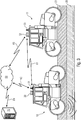
- Fig. 3 shows two rollers 10 and 11, which drive over a surface to be compacted 21 while compacting the substrate 20.
- a roll dressing is used for example in road construction, since the applied asphalt material cools down very quickly and the surface can not be compacted quickly enough with a roller.
- the determined data such as positions and compaction values
- the rollers 10 and 11 are exchanged between the rollers 10 and 11 via communication units (not shown) arranged on the rollers and antennas 31 and 33 via a communication connection 81.
- all recorded and calculated data such as positions and compression values, can be logged on the server 70 in order to subsequently evaluate the performed compaction work.
- rollers are still in use at the construction site, it would also be conceivable to exchange data via a server 70 with which the individual rollers communicate via a network 50.
- communication links 82 and 83 are established between the rollers 10 and 11 and the network 50, the server 70 being connected to the network 50 via a connection 84.
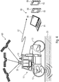
- Fig. 4 shows that the determined data such as positions and compression values can also be transmitted to a mobile device 90 via the communication unit (not shown) arranged on the roller 10 and the antennas 31 via a communication connection 85.
- a mobile device 90 may be, for example, a laptop 91, a smartphone 92 or a tablet PC 93.
- a smartwatch or a data glasses or the like can receive the signals emitted by the antenna 31 signals 85.
- Each of the mobile devices 90 has a corresponding interface 88 for receiving the data.
- An installed and executable on said mobile devices 90 software is able to display based on the received data, for example, the compaction values of the substrate or machine parameters of the roller graphically on a display of the mobile device or in the data glasses d. H. to visualize for the driver of the roller or also for the construction site personnel working on the construction site or in a construction site office. Also, all recorded and calculated data, such as positions and compression values, may be logged on the mobile terminal 90, i. H. be stored in order to be able to subsequently evaluate the compaction work carried out.
- a software installed and executable on the server 70 or on the mobile terminal 90 can perform a classification of the rollers on the basis of the data which were determined on the first passage of one or more rollers over the road surface.
- a software installed and executable on the server 70 or on the mobile terminal 90 can perform a classification of the rollers on the basis of the data which were determined on the first passage of one or more rollers over the road surface.
- heavy rollers are used with a greater compaction performance and in places or in sections where only slightly or no longer needs to be compressed, only smaller or lighter rollers are used.
- a division of sections may also be used to prohibit further driving over certain sections / areas, ie. H. Zones are defined in which the rollers are not allowed to retract.
- the software installed and executable on the server 70 or on the mobile terminal 90 performs calculations for this purpose and transmits the corresponding data to the individual rollers, so that there is, for example, a corresponding message or a message / alarm on an on-board computer for the driver of the roller.
- the above-mentioned server 70 it is possible to use the above-mentioned server 70 not only to exchange data of the actual compression data, but also to Logging purposes. In this case, preferably all recorded calculated data are logged in order to be able to subsequently prove and evaluate the compaction work that has been carried out.
- the adjustment of the compaction performance takes place in such a way that, in addition to the machine control parameter, a selection of the machine type also takes place for a further iteration.
- different machines can perform different compaction work, for example due to different impressed performances or different weights. For example, assuming that in the first iteration a very heavy compaction machine is compacted and the actual compaction values are taken, a different machine may be used for the second iteration where appropriate machine control parameters are adjusted.
- a possible scenario would therefore be that a heavy compaction roller is used at points or paths where a large compaction is necessary, while in other places where only slightly compacted, a lighter compaction roller is used.
- individual sections do not have to be compressed at all, so that these sections or even whole zones are blocked for further passage, so that individual sections are provided with a blocking instruction, so that the rollers no longer retract here allowed.
- the compression or the individual compaction performance often depends on a surface temperature or a material temperature of the material to be incorporated, such. B. from the street to be installed. Therefore, according to embodiments temperature sensors may be provided, the z. B. are connected via the above-explained interface 1 S with the device 1 to the temperature, for. B. on the roller to monitor the asphalt compaction.
- the temperature data is recorded and a cooling behavior is calculated, which is included in the calculation of the compaction power of the roller to be set.
- a compression capacity must be reduced more or less. Note: After the first crossing of a roller over a freshly applied asphalt layer, its surface becomes Smoothed, so that the cooling behavior of the asphalt changed by the changed heat transfer between asphalt and the environment.
- aspects have been described in the context of a device, it will be understood that these aspects also constitute a description of the corresponding method, so that a block or a component of a device is also to be understood as a corresponding method step or as a feature of a method step. Similarly, aspects described in connection with or as a method step also represent a description of a corresponding block or detail or feature of a corresponding device.
- Some or all of the method steps may be performed by a hardware device (or using a hardware device). Apparatus), such as a microprocessor, a programmable computer or an electronic circuit. In some embodiments, some or more of the most important method steps may be performed by such an apparatus.
- embodiments of the invention may be implemented in hardware or in software.
- the implementation may be performed using a digital storage medium, such as a floppy disk, a DVD, a Blu-ray Disc, a CD, a ROM, a PROM, an EPROM, an EEPROM or FLASH memory, a hard disk, or other magnetic disk or optical memory are stored on the electronically readable control signals that can cooperate with a programmable computer system or cooperate such that the respective method is performed. Therefore, the digital storage medium can be computer readable.
- some embodiments according to the invention include a data carrier having electronically readable control signals capable of interacting with a programmable computer system such that one of the methods described herein is performed.
- embodiments of the present invention may be implemented as a computer program product having a program code, wherein the program code is operable to perform one of the methods when the computer program product runs on a computer.
- the program code can also be stored, for example, on a machine-readable carrier.
- inventions include the computer program for performing any of the methods described herein, wherein the computer program is stored on a machine-readable medium.
- an embodiment of the method according to the invention is thus a computer program which has a program code for performing one of the methods described herein when the computer program runs on a computer.
- a further embodiment of the inventive method is thus a data carrier (or a digital storage medium or a computer-readable medium) on which the computer program is recorded for carrying out one of the methods described herein.
- a further embodiment of the method according to the invention is thus a data stream or a sequence of signals, which represent the computer program for performing one of the methods described herein.
- the data stream or the sequence of signals may be configured, for example, to be transferred via a data communication connection, for example via the Internet.
- Another embodiment includes a processing device, such as a computer or a programmable logic device, that is configured or adapted to perform one of the methods described herein.
- a processing device such as a computer or a programmable logic device, that is configured or adapted to perform one of the methods described herein.
- Another embodiment includes a computer on which the computer program is installed to perform one of the methods described herein.
- Another embodiment according to the invention comprises a device or system adapted to transmit a computer program for performing at least one of the methods described herein to a receiver.
- the transmission can be done for example electronically or optically.
- the receiver may be, for example, a computer, a mobile device, a storage device or a similar device.
- the device or system may include a file server for transmitting the computer program to the recipient.
- a programmable logic device eg, a field programmable gate array, an FPGA
- a field programmable gate array may cooperate with a microprocessor to perform one of the methods described herein.
- the methods are performed by any hardware device. This may be a universal hardware such as a computer processor (CPU) or hardware specific to the process, such as an ASIC.
Landscapes
- Engineering & Computer Science (AREA)
- Architecture (AREA)
- Civil Engineering (AREA)
- Structural Engineering (AREA)
- Road Paving Machines (AREA)
Abstract
Eine Vorrichtung zur Verdichtungssteuerung für die Verdichtung eines Bereichs eines Untergrunds mittels einer Straßen- oder Bodenverdichtungsmaschine umfasst eine Schnittstelle zum Empfangen von Ist-Verdichtungswerten, eine Berechnungseinheit sowie eine Steuerung. Die Berechnungseinheit ist dazu ausgebildet, um die Ist-Verdichtungswerte mit den Soll-Verdichtungswerten zu vergleichen, um Plan-Verdichtungswerte zu erhalten Die Steuerung ist ausgebildet, um ausgehend von den Plan-Verdichtungswerten Maschinensteuerparameter für die Straßen- oder Verdichtungsmaschine zu bestimmen, in Abhängigkeit von welchem die Verdichtung in den jeweiligen Abschnitten erfolgt.A compacting control apparatus for compacting an area of a ground by a road or soil compaction machine includes an interface for receiving actual compaction values, a calculation unit, and a controller. The computation unit is configured to compare the actual compaction values with the target compaction values to obtain plan compaction values. The controller is configured to determine machine control parameters for the road or compaction machine based on the plan compaction values, as a function of which the compaction takes place in the respective sections.
Description
Ausführungsbeispiele der vorliegenden Erfindung schaffen eine Vorrichtung sowie ein Verfahren zur Verdichtungssteuerung. Weitere Ausführungsbeispiele schaffen eine Straßen- oder Bodenverdichtungsmaschine mit entsprechender Steuerung.Embodiments of the present invention provide an apparatus and method for compaction control. Further embodiments provide a road or Bodenverdichtungsmaschine with appropriate control.
Im Allgemeinen betrifft die vorliegende Erfindung das Gebiet von Walzen, beispielsweise von Straßenwalzen zum Verdichten einer Straßen- oder Fahrbahnoberfläche. Ein bevorzugtes Ausführungsbeispiel der Erfindung betrifft ein Verfahren zur Verdichtungsregelung einer durch eine Walze zu verdichtende Materialschicht, wie beispielsweise Erd- oder Asphaltschicht.In general, the present invention relates to the field of rollers, for example, road rollers for compacting a road or road surface. A preferred embodiment of the invention relates to a method for controlling the compression of a material layer to be compacted by a roller, such as earth or asphalt layer.
Als Resultat der Verdichtungsarbeit einer Walze ist in der Regel ein homogenes und ausreichend verdichtetes Feld erwünscht, denn dieses ist die Voraussetzung für hochtragfähige Böden und langlebige Straßenbeläge.As a result of the compaction work of a roller, a homogeneous and sufficiently compacted field is generally desirable because this is the prerequisite for highly loadable floors and durable road surfaces.
Im Straßenbau ist es wichtig, dass der von Straßenfertigern aufgebrachte Straßenbelag, wie beispielsweise Asphaltmaterial, anschließend von Straßenwalzen verdichtet wird. Dazu bewegen sich eine oder mehrere Straßenwalzen während des Arbeitseinsatzes in einem von einem oder mehreren Straßenfertigern vorgegebenen Gebiet, in dem Asphaltmaterial ausgebracht wurde. Um das Asphaltmaterial ausreichend zu verdichten, wird jeder Bereich der Straße mehrmals von einer Straßenwalze überfahren. Dazu fährt die Straßenwalze den Straßenbelag in mehreren Bahnen ab, da dieser üblicherweise breiter ist als die Walzenbandage. Nachdem die Straßenwalze in einzelnen Bahnen den Straßenbelag ein erstes Mal überfahren hat, beginnt diese dann mit einer weiteren Überfahrt bei der ersten bereits überfahrenen Bahn.In road construction, it is important that the road surface applied by road pavers, such as asphalt material, is subsequently compacted by road rollers. For this purpose, move one or more road rollers during the labor input in a specified by one or more road pavers area in which asphalt material was applied. To densify the asphalt material sufficiently, each area of the road is run over several times by a road roller. For this purpose, the road roller drives off the road surface in several tracks, as this is usually wider than the roller drum. After the road roller has run over the road surface in individual lanes for a first time, this then begins with another crossing at the first track already crossed over.
Bei den bekannten Systemen werden Verdichtungswerte der zu verdichtenden Fläche während des Walzens (Verdichtens) gemessen und dem Fahrer auf einem Monitor oder Display angezeigt. Beispielsweise sind aus der
Weiterhin beschreibt die
Dabei erfolgt eine Bestimmung des Verdichtungsgrades in der Regel bei jeder Überfahrt der Walze über die zu verdichtende Fläche, indem die in den Untergrund eingebrachten bzw. in den Untergrund wirkenden Kräfte mittels eines Verdichtungsmessers gemessen werden. Aus den gemessenen Werten kann dann ein Grad der Verdichtung des Untergrunds berechnet werden. Somit kann durch mehrmaliges Überfahren über die zu verdichtende Fläche eine Änderung der Verdichtung des Untergrunds ermittelt werden. Ein solches Messsystem ist beispielsweise in der
Ein mehrmaliges Überfahren der Walze über einen Untergrund kann allerdings auch schnell zu einer Überverdichtung oder aber auch zu Schädigungen des Untergrunds führen, beispielsweise wenn dieser unterschiedliche Unterbauten aufweist oder darin Ver- oder Entsorgungsleitungen verlaufen. So kann ein Unterbau zum Beispiel verschiedene Materialien wie Erde, Sand, Steine oder Fels, oder aber auch bereits verlegte Abwasser- bzw. Kanalrohre, Schächte oder Ähnliches, aufweisen und somit eine Verdichtung in diesem Bereich beeinflussen. D. h., eine optimale Verdichtung des Unterbaus wird an solchen Stellen beispielsweise schon früher erreicht als an anderen Stellen, in deren Unterbau keine Rohre oder Ähnliches verlaufen. Sind in dem Unterbau bereits Ver- oder Entsorgungsleitungen und/oder Rohre, Schächte oder Ähnliches eingebracht, so kann eine Überverdichtung in diesen Bereichen diese beschädigen, was mitunter auch zu hohen Reparaturkosten führen kann.However, a repeated crossing of the roller over a substrate can also quickly lead to over-compression or even damage to the ground, for example, if this has different substructures or run in supply or disposal lines. Thus, a substructure, for example, various materials such as earth, sand, stone or rock, or even laid wastewater or sewer pipes, manholes or the like, and thus have a compression in this area influence. D. h., An optimal compaction of the substructure is, for example, reached earlier in such places than at other locations in the substructure no pipes or the like run. Are in the substructure already introduced supply or disposal lines and / or pipes, manholes or the like, so over-compression in these areas can damage them, which can sometimes lead to high repair costs.
Da es bei den bekannten Systemen im Wesentlichen dem Fahrer obliegt, die entsprechenden Parameter (Verdichtungsleistung) der Maschine während des Verdichtungsvorganges einzustellen, kann insbesondere bei den beschriebenen Untergründen mit unterschiedlichen Unterbauten eine optimale Verdichtung nicht immer erreicht werden, da für den Fahrer verschiedene Materialien im Unterbau oder darin verlaufende Rohre oder Ähnliches nicht ersichtlich sein können. Deshalb besteht der Bedarf nach einem verbesserten Ansatz.Since it is incumbent on the driver in the known systems essentially to adjust the corresponding parameters (compaction performance) of the machine during the compaction process, optimum compaction can not always be achieved, in particular for the described substrates with different substructures, since the driver has different materials in the substructure or pipes or the like extending therethrough may not be apparent. Therefore, there is a need for an improved approach.
Aufgabe der vorliegenden Erfindung ist es ein Konzept zur Verdichtungssteuerung mit erhöhter Genauigkeit zu schaffen.The object of the present invention is to provide a concept for compaction control with increased accuracy.
Die Aufgabe wird durch den Gegenstand der unabhängigen Patentansprüche gelöst.The object is solved by the subject matter of the independent patent claims.
Ausführungsbeispiele der vorliegenden Erfindung schaffen eine Vorrichtung zur Verdichtungssteuerung für die Verdichtung eines Bereichs eines Untergrunds mittels einer Stra-ßen- oder Bodenverdichtungsmaschine. Die Vorrichtung umfasst eine Schnittstelle, eine Berechnungseinheit und eine Steuerung. Über die Schnittstelle werden Ist-Verdichtungswerte, nämlich ein erster Ist-Verdichtungswert für einen ersten Abschnitt des Bereichs und ein zweiter Ist-Verdichtungswert für einen zweiten Abschnitt des Bereichs ermittelt. Die Berechnungseinheit ist ausgebildet, um den ersten Ist-Verdichtungswert mit einem ersten Soll-Verdichtungswert für den ersten Abschnitt zu vergleichen, um einen ersten Plan-Verdichtungswert (d. h. einen Verdichtungswert für beispielsweise eine nächste Iteration) für diesen ersten Bereich zu ermitteln. Weiter vergleicht die Berechnungseinheit einen zweiten Ist-Verdichtungswert mit einem zweiten Soll-Verdichtungswert für den zweiten Abschnitt, um einen zweiten Plan-Verdichtungswert für diesen Bereich (beispielsweise wiederum für die nächste Iteration) zu ermitteln. Die Steuerung der Verdichtungssteuerung bestimmt nun einen ersten Maschinensteuerparameter ausgehend von einem ersten Plan-Verdichtungswert für die Straßen- oder Verdichtungsmaschine, wobei in Abhängigkeit von dem ersten Maschinensteuerparameter die Verdichtung des ersten Abschnitts erfolgt bzw. erfolgen soll. Analog hierzu wird ausgehend von dem zweiten Plan-Verdichtungswert ein zweiter Maschinensteuerparameter für die Straßen- oder Bodenverdichtungsmaschine ermittelt, ausgehend von welchem die Verdichtung des zweiten Abschnitts erfolgt bzw. erfolgen soll.Embodiments of the present invention provide a compacting control apparatus for compacting a portion of a subsurface by means of a road or soil compaction machine. The device comprises an interface, a calculation unit and a controller. Actual compression values, namely a first actual compression value for a first portion of the range and a second actual compression value for a second portion of the range, are determined via the interface. The calculation unit is configured to compare the first actual compression value with a first target compression value for the first portion to determine a first plan compression value (i.e., a compression value for, for example, a next iteration) for that first range. Further, the calculation unit compares a second actual compression value with a second target compression value for the second portion to determine a second plan compression value for that range (again, for example, for the next iteration). The control of the compaction control now determines a first machine control parameter based on a first plan compaction value for the road or compaction machine, wherein the compaction of the first section takes place or should take place as a function of the first machine control parameter. Analogously, starting from the second plan compression value, a second machine control parameter for the road or soil compaction machine is determined, starting from which the compaction of the second section takes place or is to take place.
Entsprechend Ausführungsbeispielen erfolgt die Verdichtung in mehreren Iterationen, so dass der erste und der zweite Abschnitt mehrfach überfahren werden. Bei der ersten Überfahrt (ersten Iteration) wird der erste und zweite Ist-Verdichtungswert für einen ersten bzw. zweiten Bereich ermittelt. Entsprechend Ausführungsbeispielen kann dieser erste und zweite Ist-Verdichtungswert dann zwischengespeichert werden, so dass dann bei bzw. vor der zweiten Iteration der erste und zweite Ist-Verdichtungswert aus der ersten Iteration mit dem ersten und zweiten Soll-Verdichtungswert für den ersten und zweiten Abschnitt verglichen wird, um dann den ersten und zweiten Plan-Verdichtungswert für die zweite Iteration zu erhalten. Analog hierzu kann für eine dritte Iteration ausgehend von den Ist-Verdichtungswerten der zweiten Iteration die entsprechenden Plan-Verdichtungswerte für die dritte Iteration, z. B. durch Anpassen der Plan-Verdichtungswerte aus der zweiten Iteration erhalten werden.According to embodiments, the compression takes place in several iterations, so that the first and the second section are run over several times. In the first Crossing (first iteration), the first and second actual compression value for a first and second area is determined. According to exemplary embodiments, this first and second actual compression value can then be temporarily stored, so that then, during and before the second iteration, the first and second actual compression values from the first iteration are compared with the first and second desired compression values for the first and second sections and then obtain the first and second plan compression values for the second iteration. Similarly, for a third iteration, starting from the actual compression values of the second iteration, the corresponding plan compression values for the third iteration, e.g. By adjusting the plan compression values from the second iteration.
Ausführungsbeispielen der vorliegenden Erfindung liegt also die Erkenntnis zugrunde, dass durch abschnittsweises Abgleichen der Ist-Verdichtungswerte in Bezug auf die Soll-Verdichtungswerte eine Größe bestimmt werden kann, die zur Steuerung bzw. Regulierung der Verdichtung in dem betreffenden Abschnitt genutzt werden kann. Entsprechend Ausführungsbeispielen kann hierbei beispielsweise die Verdichtungsleistung der Maschine (beispielsweise Vibrationsfrequenz und/oder Amplitude) oder aber auch eine Überfahrtgeschwindigkeit reguliert werden. Der Vorteil dieses Ansatzes liegt darin, dass bereits vor einer weiteren Überfahrt über einen bereits vorverdichteten Bereich die Verdichtungsleistung vermindert werden kann und so eine etwaige Überverdichtung des Untergrunds vermieden wird. Mit anderen Worten ausgedrückt heißt das, dass im Vergleich zum Stand der Technik bereits vor einer weiteren Überfahrt die Verdichtungsleistung zurückgeregelt werden kann, um einen etwaigen Fehler (Überverdichtung) zu vermeiden. Weiterhin wird durch das oben beschriebene Konzept auch der Verschleiß der Maschine (z. B. des Straßen/Bodenverdichters oder der Walze) sowie der Kraftstoffverbrauch reduziert, da die in das Material eingebrachte Verdichtungsleistung unter Berücksichtigung der Vorverdichtung anhand der bereits vorgegebenen Verdichtungswerten des Untergrunds angepasst wird.Embodiments of the present invention are therefore based on the finding that a size which can be used to control or regulate the compression in the relevant section can be determined by adjusting the actual compression values in relation to the target compression values in sections. According to embodiments, for example, the compaction power of the machine (for example, vibration frequency and / or amplitude) or even a crossing speed can be regulated. The advantage of this approach is that even before another crossing over an already pre-compressed area, the compression capacity can be reduced and thus any over-compaction of the subsurface is avoided. In other words, this means that in comparison to the prior art, the compression capacity can be regulated back before another crossing in order to avoid a possible error (over-compression). Furthermore, the above-described concept also reduces the wear of the machine (eg the road / ground compressor or the roller) as well as the fuel consumption, since the compaction power introduced into the material is adjusted taking into account the precompression on the basis of the already specified compaction values of the ground ,
Die eingangs aufgeführten Nachteile werden somit überwunden, da es nicht mehr dem Fahrer überlassen bleibt, die Verdichtungsleistung der Maschine entsprechend einzustellen bzw. zu verändern. Es wird demnach eine, über die zu verdichtende Fläche gesehen, gleichmäßigere Verdichtung erreicht, da die Verdichtungsleistung der Maschine ab der zweiten Überfahrt an die Beschaffenheit des Untergrunds angepasst wird. Außerdem werden dadurch auch evtl. Beschädigungen an bspw. bereits im Boden verlegten Rohren, Kanälen oder Ähnlichem vermieden.The disadvantages listed above are thus overcome, since it is no longer up to the driver to adjust or change the compaction performance of the machine accordingly. Accordingly, a more uniform compaction is achieved over the area to be compacted, since the compaction performance of the machine is adapted to the condition of the subsoil from the second pass. In addition, any damage to eg. Already laid in the ground pipes, channels or the like are thereby avoided.
Entsprechend Ausführungsbeispielen ist jedem Ist-Verdichtungswert, Soll-Verdichtungswert und Plan-Verdichtungswert ein Positionswert zugeordnet. Hierbei kann entsprechend weiteren Ausführungsbeispielen die Vorrichtung einen Positionssensor umfassen, der ausgebildet ist, um dem Ist-Verdichtungswert und/oder dem Plan-Verdichtungswert einen Positionswert zuzuordnen. Entsprechend Ausführungsbeispielen können die Abschnitte des Bereichs eine kontinuierliche oder eine variierende laterale Ausdehnung umfassen, so dass also je nach Bedarf auch eine feingraduellere Unterteilung des zu verdichtenden Bereichs möglich ist.According to embodiments, a position value is assigned to each actual compression value, target compression value and plan compression value. In this case, according to further exemplary embodiments, the device may comprise a position sensor which is designed to associate a position value with the actual compression value and / or the plan compression value. According to exemplary embodiments, the sections of the area may comprise a continuous or a varying lateral extent, so that, depending on requirements, a finely divellable subdivision of the area to be compacted is also possible.
Zum Ermitteln der Ist-Verdichtungswerte gibt es im Prinzip zwei unterschiedliche Ansätze. Entsprechend einem ersten Ansatz kann die Vorrichtung einen Verdichtungsgradsensor umfassen, der bei einer vorangegangenen Iteration die Ist-Verdichtung ermittelt, um zu ermöglichen, dass für die aktuelle Iteration der Plan-Verdichtungswert durch den oben erläuterten Vergleich berechnet werden kann. Entsprechend einer zweiten Variante kann entsprechend Ausführungsbeispielen die Vorrichtung eine Funkschnittstelle umfassen, die beispielsweise von einem anderen Straßen- oder Bodenverdichter einen Ist-Verdichtungswert über einen dort angeordneten Sensor empfängt. Diese Variante ist insbesondere dann vorteilhaft, wenn mit mehreren hintereinanderfahrenden Straßen/Bodenverdichtern die Verdichtung erfolgen soll, so dass der hinterherfahrende Straßenverdichter (entspricht der zweiten Iteration bzw. der zweiten Verdichtung) seine Verdichtungsleistung ausgehend von der aktuellen / gemessenen Ist-Verdichtung für den noch zu überfahrenden Bereich anpasst, wobei der Ist-Verdichtungswert durch die vorausfahrende Verdichtungsmaschine ermittelt ist.To determine the actual compression values, there are in principle two different approaches. According to a first approach, the device may include a compression degree sensor which, in a previous iteration, determines the actual compression to allow the plan compression value for the current iteration to be calculated by the comparison discussed above. According to a second variant, according to embodiments, the device may comprise a radio interface which receives, for example, from another road or ground compressor an actual compression value via a sensor arranged there. This variant is particularly advantageous if the compression is to take place with a plurality of road / ground compressors driving one behind the other, so that the downstream road compressor (corresponding to the second iteration or the second compression) its compression power starting from the current / measured actual compression for the still overrunning area, wherein the actual compression value is determined by the preceding compacting machine.
Entsprechend weiteren Ausführungsbeispielen kann bei der Berechnung der Plan-Verdichtungswerte auch ein Ist-Temperaturwert, der beispielsweise zusammen mit dem Ist-Verdichtungswert ermittelt ist, Berücksichtigung finden. Hierbei kann beispielsweise eine sogenannte Simulation des Abkühlverhaltens mit den Eingangsparametern der Ist-Temperaturwerte für den jeweiligen Bereich herangezogen werden.According to further embodiments, when calculating the plan-compression values, an actual temperature value, which is determined, for example, together with the actual compression value, can also be taken into account. In this case, for example, a so-called simulation of the cooling behavior with the input parameters of the actual temperature values for the respective area can be used.
Ein weiteres Ausführungsbeispiel bezieht sich auf eine Straßen- bzw. Bodenverdichtungsmaschine, wie z. B. eine Walze mit einer entsprechenden Vorrichtung. Entsprechend einem Ausführungsbeispiel ist diese Straßen- bzw. Bodenverdichtungsmaschine dazu ausgebildet, die Verdichtungsleistung (z. B. die Amplitude oder die Frequenz einer vibrierenden Bandage) in Abhängigkeit von den ersten und zweiten Maschinensteuerparametern anzupassen bzw. zu wählen. Hierbei kann entsprechend einem Ausführungsbeispiel die Verdichtungsleistung abschnittsweise variiert werden, d. h. also, dass der erste Abschnitt mit einer anderen additiven Verdichtung verdichtet wird als der zweite Abschnitt. Hierbei kann die Leistung auch auf null reduziert werden. Entsprechend einem weiteren Ausführungsbeispiel ist es auch möglich, einen Bereich für eine weitere Überfahrt zu sperren. Alternativ oder additiv zu der Variation der Verdichtungsleistung kann entsprechend Ausführungsbeispielen die Bewegungsgeschwindigkeit der Straßen- bzw. Bodenverdichtungsmaschine in Abhängigkeit von dem ersten und zweiten Maschinensteuerparameter angepasst werden.Another embodiment relates to a road or Bodenverdichtungsmaschine such. B. a roller with a corresponding device. According to one embodiment, this road compaction machine is configured to provide the compaction power (eg, the amplitude or frequency of a vibrating bandage) in response to the first and second machine control parameters to adapt or to choose. In this case, according to an exemplary embodiment, the compression power can be varied in sections, ie, so that the first section is compressed with a different additive compression than the second section. This can also reduce the power to zero. According to a further embodiment, it is also possible to lock an area for another crossing. Alternatively or in addition to the variation of the compaction performance, the speed of movement of the road compaction machine can be adapted in accordance with embodiments according to the first and second machine control parameters.
Ein weiteres Ausführungsbeispiel bezieht sich auf ein Verfahren zur Verdichtungssteuerung mit den Schritten Empfangen der Ist-Verdichtungswerte, Vergleichen der Ist-Verdichtungswerte mit den Soll-Verdichtungswerten für die jeweiligen Abschnitte und Ermitteln zumindest des ersten und zweiten Maschinensteuerparameters basierend auf den Plan-Verdichtungswerten. Das Verfahren kann entsprechend weiteren Ausführungsbeispielen computerimplementiert ausgeführt werden, d. h. also, dass entsprechend einem Ausführungsbeispiel ein Computerprogramm mit einem Programmcode zur Durchführung des Verfahrens geschaffen wird.A further embodiment relates to a method for compression control comprising the steps of receiving the actual compression values, comparing the actual compression values with the target compression values for the respective sections, and determining at least the first and second engine control parameters based on the plan compression values. The method can be carried out computer-implemented according to further embodiments, i. H. Thus, according to one exemplary embodiment, a computer program with a program code for carrying out the method is created.
Weiterbildungen sind in den Unteransprüchen definiert. Ausführungsbeispiele der vorliegenden Erfindung werden anhand der beiliegenden Zeichnungen erläutert. Es zeigen:
- Fig. 1 a, b
- eine schematische Darstellung einer Vorrichtung zur Verdichtungssteuerung gemäß einem Basisausführungsbeispiel zusammen mit einem zu verdichtenden Bereich;
- Fig. 2a-b
- schematische Darstellungen zur Illustration der Verwendung der Vorrichtung aus
Fig. 1 bei einer Walze aus Straßen- bzw. Bodenverdichtungsmaschine gemäß einem erweiterten Ausführungsbeispiel; - Fig. 3
- eine schematische Darstellung der Vorrichtung zur Verdichtungssteuerung bei Einsatz in einer oder mehreren Walzen als Boden-/Straßenverdichtungsmaschinen gemäß erweiterten Ausführungsbeispielen; und
- Fig. 4
- eine schematische Darstellung der Vorrichtung zur Verdichtungssteuerung in Kombination mit einer Walze gemäß einem zusätzlichen Ausführungsbeispiel.
- Fig. 1 a, b
- a schematic representation of a device for compaction control according to a basic embodiment together with a region to be compacted;
- Fig. 2a-b
- schematic representations illustrating the use of the device
Fig. 1 in a roller of road compaction machine according to an extended embodiment; - Fig. 3
- a schematic representation of the device for compacting control when used in one or more rollers as soil / Straßenverdichtungsmaschinen according to extended embodiments; and
- Fig. 4
- a schematic representation of the device for compacting control in combination with a roller according to an additional embodiment.
Bevor nachfolgend Ausführungsbeispiele der vorliegenden Erfindung anhand der beiliegenden Zeichnungen erläutert werden, sei darauf hingewiesen, dass gleiche und gleichwirkende Elemente und Strukturen mit gleichen Bezugszeichen versehen sind, so dass die Beschreibung derer aufeinander anwendbar bzw. austauschbar ist.Before explaining embodiments of the present invention with reference to the accompanying drawings, it should be noted that like and equivalent elements and structures are provided with the same reference numerals, so that the description of which is mutually applicable or interchangeable.
Die Vorrichtung 1 umfasst beispielsweise eine Schnittstelle 1S zum Empfangen von aktuellen Verdichtungswerten, wie z. B. gemessenen Verdichtungswerten für die Bereiche A1 und A2, eine Berechnungseinheit 1 B sowie eine Steuerung 1C.The
Die Schnittstelle 1S empfängt Ist-Verdichtungswerte für die Abschnitte A1 und A2, d. h. zumindest den ersten und den zweiten Ist-Verdichtungswert. Hierbei sei angemerkt, dass die Untergliederung des Bereichs 21 in eine beliebige Anzahl an Abschnitten möglich ist, so dass über die Schnittstelle 1S auch weitere Verdichtungswerte empfangen werden können. Der erste und der zweite Ist-Verdichtungswert wird der nachgelagerten Berechnungseinheit 1 B zur Verfügung gestellt. Die Berechnungseinheit 1 B erhält von extern, z. B. von einem Planungsbüro unter Zuhilfenahme einer Funkschnittstelle die entsprechenden Soll-Verdichtungswerte, d. h. den ersten Soll-Verdichtungswert für einen ersten Abschnitt A1 sowie den zweiten Soll-Verdichtungswert für den zweiten Abschnitt A2. Weitere Soll-Verdichtungswerte können natürlich je nach Untergliederung des Bereichs 21 auch erhalten werden. Die Berechtigungseinheit vergleicht nun die erhaltenen Ist-Verdichtungswerte mit den Soll-Verdichtungswerten für die jeweiligen Abschnitte, um abschnittsweise sogenannte Plan-Verdichtungswerte, d. h. also einen ersten Plan-Verdichtungswert für den Abschnitt A1 sowie einen zweiten Plan-Verdichtungswert für den Abschnitt A2 zu erhalten.The
Ausgehend von diesen Plan-Verdichtungswerten für die unterschiedlichen Abschnitte A1 und A2 wird nun mittels einer Steuerung 1C, die auch beispielsweise Teil der Straßen- oder Bodenverdichtungsmaschine (nicht dargestellt) sein kann, die Steuerung der Straßen- oder Bodenverdichtungsmaschine durchgeführt. Hierzu ermittelt die Steuerung ausgehend von den Plan-Verdichtungswerten die jeweiligen Maschinensteuerparameter, in Abhängigkeit von welchen die Verdichtung der Abschnitte A1 und A2 erfolgen soll. Die Zuordnung eines ersten Maschinensteuerparameters zu dem Abschnitt A1 sowie eines zweiten Maschinensteuerparameters zu dem Abschnitt A2 besteht fort.Based on these plan compression values for the different sections A1 and A2, the control of the road or soil compaction machine is now carried out by means of a controller 1C, which may also be part of the road or soil compaction machine (not shown), for example. For this purpose, the control determines, based on the plan compression values, the respective machine control parameters, as a function of which the compression of sections A1 and A2 is to take place. The assignment of a first machine control parameter to the section A1 and a second machine control parameter to the section A2 continues.
Diese Maschinensteuerparameter können beispielsweise eine Beeinflussung der Verdichtungsleistung bewirken, indem beispielsweise die Frequenz und/oder Amplitude der Vibrationen in Abhängigkeit von dem Maschinensteuerparameter angepasst wird.These machine control parameters can, for example, influence the compaction performance, for example by adjusting the frequency and / or amplitude of the vibrations as a function of the machine control parameter.
Entsprechend einer Alternative kann ein Maschinensteuerparameter dazu eingesetzt werden, um eine Überfahrgeschwindigkeit der einzelnen Abschnitte A1 und A2 zu regulieren.According to an alternative, a machine control parameter may be used to regulate a speed of travel of the individual sections A1 and A2.
An dieser Stelle sei angemerkt, dass die Verdichtung des Belags 21 mit den Abschnitten A1 und A2 im Regelfall in mehrere Iterationen erfolgt. Weiter ist es auch häufig so, dass die Vorrichtung 1 auf einer Straßen/Bodenverdichtungsmaschine angeordnet ist, so dass auch der Sensor zur Ermittlung der Ist-Verdichtungswerte auf derselben Maschine angeordnet ist. Dies hat die Konsequenz , dass beim Messen des ersten Ist-Verdichtungswerts bereits mittels einer vorgegebenen Verdichtungsleistung bzw. Geschwindigkeit die Verdichtung des Abschnitts A1 erfolgt. Ebenso verhält es sich auch bei der Verdichtung des Abschnitts A2. Der Hintergrund hierzu ist neben der Anordnung auch das häufig bei der Verdichtungsmessung eingesetzte Messprinzip, entsprechend welchem die Frequenzantwort des Untergrunds im Abschnitt A1 oder A2 auf die eingebrachte Vibrationsenergie ausgewertet wird.It should be noted at this point that the compaction of the lining 21 with the sections A1 and A2 generally takes place in a plurality of iterations. Furthermore, it is also frequently the case that the
Entsprechend Ausführungsbeispielen werden also die bei der ersten Iteration erhaltenen Ist-Verdichtungswerte für die Abschnitte A1 und A2 dazu verwendet, um die Plan-Verdichtungswerte für die jeweiligen Abschnitte A1/A2 zu berechnen, ausgehend von welchen die Verdichtungsleistung in der zweiten Iteration angepasst wird.According to embodiments, the actual compression values for the sections A1 and A2 obtained in the first iteration are used to calculate the plan compression values for the respective sections A1 / A2, starting from which the compression power is adjusted in the second iteration.
An dieser Stelle sei auch angemerkt, dass entsprechend Ausführungsbeispielen die Verdichtungsleistung von Abschnitt zu Abschnitt variieren kann, so dass beispielsweise die noch benötige Verdichtung beim Abschnitt A1 kleiner ist als die noch benötigte Verdichtung als beim Abschnitt A2.It should also be noted at this point that, according to exemplary embodiments, the compression capacity can vary from section to section, so that, for example, the still required compression at section A1 is smaller than the compression still required than at section A2.
Entsprechend weiteren Ausführungsbeispielen kann sich ein Verfahren zur Verdichtungsregelung wie folgt darstellen: Verfahren zur Verdichtungsregelung einer durch eine Walze zu verdichtenden Materialschicht 21, wie beispielsweise Erd- oder Asphaltschicht, wobei die Walze eine Vorrichtung 1 zur Regelung der Verdichtungsleistung, ein Messsystem zum Bestimmen eines Verdichtungswertes der Materialschicht und ein optionales Positionsbestimmungssystem (GNSS / GPS) aufweist, und mit einem vorbestimmten Endverdichtungswert der zu verdichtenden Materialschicht, mit folgenden Schritten:
- (a) Bestimmen von Positionsdaten zu Beginn eines Abschnitts der zu verdichtenden Materialschicht;
- (b) Überfahrt der Walze über den Abschnitt mit einer ersten Verdichtungsleistung;
- (c) Bestimmen von mindestens einem Verdichtungswert der Materialschicht während des Verdichtungsvorgangs;
- (d) Abspeichern der Positionsdaten
- (a) determining position data at the beginning of a portion of the material layer to be compacted;
- (b) passing the roller over the section at a first compaction power;
- (c) determining at least one compaction value of the material layer during the compaction process;
- (d) storing the position data
Bei oben erläutertem Ansatz ist auch denkbar, dass die Ist-Verdichtungswerte mittels einer anderen Maschine, z. B. einer anderen Verdichtungsmaschine ermittelt werden und dann an die Verdichtungsmaschine mit der Vorrichtung 1 per Funk übertragen werden, so dass die Vorrichtung 1 bei ihrer ersten Überfahrt direkt die Plan-Verdichtungswerte ausgehend von den erhaltenen Ist-Verdichtungswerten ermittelt. Das heißt also. dass die bei der ersten Überfahrt ermittelten Daten gemäß Schritt (d) sind übertragbar an andere Walzen (entweder direkt per Funkverbindung oder indirekt durch "Ablage" auf einem Server), da im Straßenbau meist mehrere Walzen im Einsatz sind (sog. Walzenverband). Anhand dieser Daten können andere Walzen ab einer weiteren Überfahrt (ab der zweiten Überfahrt) über einen bereits vorverdichteten Abschnitt die Verdichtungsleistung der Maschine entsprechend anpassen.In the above-described approach is also conceivable that the actual compression values by means of another machine, eg. B. another compaction machine are determined and then transmitted to the compaction machine with the
Entsprechend einem weiteren Ausführungsbeispiel kann alternativ oder additiv zu der Verdichtungsleistung auch noch die Fahrgeschwindigkeit angepasst werden. Neben der Verdichtungsleistung beeinflusst auch die Fahrgeschwindigkeit der Walze eine Verdichtung des Untergrunds. Beim Walzen von Asphaltoberflächen wird für eine optimale und homogen verdichtete Oberfläche eine konstante Fahrgeschwindigkeit der Walze angestrebt. Es kann jedoch erforderlich sein, dass über einige der eingangs genannten Abschnitte, in denen bspw. der Unterbau verschiedene Materialien aufweist oder in welchem bereits Abwasser- bzw. Kanalrohre, Schächte oder Ähnliches verlegt wurden, die Walze schneller oder langsamer fahren sollte, um Beschädigungen am Untergrund zu vermeiden. Ein weiteres Beispiel in diesem Zusammenhang stellen auch Brücken dar, die üblicherweise als Untergrund eine Betondecke haben. Hier ist besonders wichtig, dass das Brückenbauwerk nach dem Walzen des Asphalts keine Beschädigungen durch die Vibration der Walzenbandage aufweist.According to a further embodiment, alternatively or in addition to the compaction performance, the driving speed can also be adjusted. In addition to the compaction performance, the speed of the roller also influences the compaction of the ground. When rolling asphalt surfaces, a constant travel speed of the roller is aimed at for an optimum and homogeneously compacted surface. However, it may be necessary that some of the above-mentioned sections in which, for example, the substructure has different materials or in which already sewage or sewer pipes, manholes or the like were laid, the roller should go faster or slower to damage the To avoid subsurface. Another example in this context are bridges, which usually have a concrete surface as a base. Here it is particularly important that the bridge structure after rolling of the asphalt has no damage due to the vibration of the roller drum.
Nachfolgend wird Bezug nehmend auf
In
Wie in
Das Verfahren sieht vor, dass zunächst, d. h. zu Beginn bzw. beim Einfahren in einen Abschnitt A1 ... D3 der zu verdichtenden Materialschicht 20, Positionsdaten der Walze 10 bestimmt werden. Die Walze 10 überfährt jeden Abschnitt A1 ... D3 im ersten Durchgang mit einer ersten Verdichtungsleistung und es wird mittels des Messsystems in jedem Abschnitt A1 ... D3 mindestens ein Verdichtungswert der Materialschicht 20 während des Verdichtungsvorgangs bestimmt. Die Positionsdaten werden zusammen mit den Verdichtungswerten abgespeichert. Vor jeder weiteren Überfahrt der Walze 10 über die Abschnitte A1 ... D3 der bereits vorverdichteten Materialschicht 20 wird die Verdichtungsleistung der Walze 10 anhand der gespeicherten Positions- und Verdichtungswerte an einen vorbestimmten und zu erreichenden Endverdichtungswert von der Vorrichtung zur Regelung der Verdichtungsleistung angepasst. Hierbei können zum Beispiel die Vibrationsfrequenz und/oder die Amplitude der Vibration der vibrierenden Walzenbandage 12 verringert werden, wenn der entsprechende Abschnitt bereits ausreichend verdichtet wurde oder eine nochmalige Überfahrt der Walze 10 mit einer unveränderten Verdichtungsleistung zu einer Überverdichtung des entsprechenden Abschnitts führen würde.The method provides that first, ie at the beginning or when entering a section A1... D3 of the
Wie in
Sollten auf der Baustelle noch weitere Walzen im Einsatz sein, so wäre auch ein Datenaustausch über einen Server 70 denkbar, mit dem die einzelnen Walzen über ein Netzwerk 50 kommunizieren. Hierzu werden Kommunikationsverbindungen 82 und 83 zwischen den Walzen 10 und 11 und dem Netzwerk 50 aufgebaut, wobei der Server 70 über eine Verbindung 84 mit dem Netzwerk 50 verbunden ist.If other rollers are still in use at the construction site, it would also be conceivable to exchange data via a
Eine auf den genannten mobilen Endgeräten 90 installierte und ausführbare Software (bspw. App) ist in der Lage, anhand der empfangenen Daten beispielweise die Verdichtungswerte des Untergrunds oder aber auch Maschinenparameter der Walze grafisch auf einem Display des mobilen Geräts bzw. in der Datenbrille anzuzeigen, d. h. für den Fahrer der Walze oder aber auch für das auf der Baustelle oder in einem Baustellenbüro tätige Baustellenpersonal zu visualisieren. Auch können alle aufgenommenen und berechneten Daten, wie beispielsweise Positionen und Verdichtungswerte, auf dem mobilen Endgerät 90 protokolliert, d. h. abgespeichert, werden, um im Nachhinein die durchgeführten Verdichtungsarbeiten auswerten zu können.An installed and executable on said
Ferner ist es möglich, dass eine auf dem Server 70 oder auf dem mobilen Endgerät 90 installierte und ausführbare Software anhand der Daten, die bei der ersten Überfahrt einer oder mehrerer Walzen über die Fahrbahnoberfläche ermittelt wurden, eine Einteilung der Walzen vornehmen kann. So können beispielsweise an Stellen bzw. in Abschnitten, an denen eine größere Verdichtung notwendig ist, schwere Walzen mit einer größeren Verdichtungsleistung eingesetzt werden und an Stellen bzw. in Abschnitten, an denen nur noch geringfügig oder gar nicht mehr verdichtet werden muss, nur kleinere oder leichtere Walzen eingesetzt werden. Eine Einteilung von Abschnitten kann auch dazu genutzt werden, dass ein weiteres Überfahren von bestimmten Abschnitten/Bereichen verboten wird, d. h. Zonen definiert werden, in die die Walzen nicht mehr einfahren dürfen. Die auf dem Server 70 oder auf dem mobilen Endgerät 90 installierte und ausführbare Software führt hierzu Berechnungen durch und übermittelt die entsprechenden Daten an die einzelnen Walzen, sodass dort beispielweise für den Fahrer der Walze ein entsprechender Hinweis oder eine Meldung/Alarm auf einem Bordcomputer erscheint.Furthermore, it is possible that a software installed and executable on the
Auch ist es entsprechend Ausführungsbeispielen möglich, den oben genannten Server 70 nicht nur zum Datenaustausch der Ist-Verdichtungsdaten zu nutzen, sondern auch zu Protokollierungszwecken. Hierbei werden vorzugsweise alle aufgenommenen berechneten Daten protokolliert, um im Nachhinein die durchgeführten Verdichtungsarbeiten nachweisen und auswerten zu können.Also, according to embodiments, it is possible to use the above-mentioned
Entsprechend weiteren Ausführungsbeispielen erfolgt die Anpassung der Verdichtungsleistung derart, dass für eine weitere Iteration neben dem Maschinensteuerparameter auch eine Wahl des Maschinentyps erfolgt. Der Hintergrund hierzu ist, dass unterschiedliche Maschinen beispielsweise aufgrund von unterschiedlichen eingeprägten Leistungen oder unterschiedlichen Gewichten unterschiedliche Verdichtungsarbeiten verrichten können. Wenn man also beispielsweise davon ausgeht, dass in der ersten Iteration mit einer sehr schweren Verdichtungsmaschine verdichtet wird und hierbei die Ist-Verdichtungswerte aufgenommen werden, so kann für die zweite Iteration eine andere Maschine eingesetzt werden, bei welcher dann entsprechende Maschinensteuerparameter angepasst werden. Ein mögliches Szenario wäre es also, dass an Stellen bzw. Bahnen, an denen eine große Verdichtung notwendig ist, eine schwere Verdichtungswalze eingesetzt wird, während an anderen Stellen, an denen nur noch geringfügig verdichtet werden muss, eine leichtere Verdichtungswalze eingesetzt wird.According to further embodiments, the adjustment of the compaction performance takes place in such a way that, in addition to the machine control parameter, a selection of the machine type also takes place for a further iteration. The background to this is that different machines can perform different compaction work, for example due to different impressed performances or different weights. For example, assuming that in the first iteration a very heavy compaction machine is compacted and the actual compaction values are taken, a different machine may be used for the second iteration where appropriate machine control parameters are adjusted. A possible scenario would therefore be that a heavy compaction roller is used at points or paths where a large compaction is necessary, while in other places where only slightly compacted, a lighter compaction roller is used.
Entsprechend Ausführungsbeispielen kann es auch sein, dass einzelne Abschnitte gar nicht mehr verdichtet werden müssen, so dass diese Abschnitte oder sogar ganze Zonen für weitere Überfahrt gesperrt werden, so dass also einzelne Abschnitte mit einem Sperrungshinweis versehen sind, so dass die Walzen hier nicht mehr einfahren dürfen.According to embodiments, it may also be that individual sections do not have to be compressed at all, so that these sections or even whole zones are blocked for further passage, so that individual sections are provided with a blocking instruction, so that the rollers no longer retract here allowed.
Wie oben bereits angedeutet, hängt die Verdichtung bzw. die einzelne Verdichtungsleistung häufig von einer Oberflächentemperatur bzw. einer Materialtemperatur des einzubauenden Materials, wie z. B. der einzubauenden Straße ab. Deshalb können entsprechend Ausführungsbeispielen Temperatursensoren vorgesehen sein, die z. B. über die oben erläuterte Schnittstelle 1 S mit der Vorrichtung 1 verbunden sind, um die Temperatur, z. B. über die Walze, für die Asphaltverdichtung zu monitoren.As already indicated above, the compression or the individual compaction performance often depends on a surface temperature or a material temperature of the material to be incorporated, such. B. from the street to be installed. Therefore, according to embodiments temperature sensors may be provided, the z. B. are connected via the above-explained
Asphalt kühlt nach dem Aufbringen durch den Straßenfertiger kontinuierlich aus. Bei der ersten Überfahrt werden die Temperaturdaten mit aufgenommen und so ein Abkühlverhalten errechnet, welches mit in die Berechnung der einzustellenden Verdichtungsleistung der Walze eingeht. In Abhängigkeit des Temperaturabfalls muss eine Verdichtungsleistung mehr oder minder stark zurückgenommen werden. Anmerkung: Nach der ersten Überfahrt einer Walze über eine frisch aufgebrachte Asphaltschicht wird deren Oberfläche geglättet, sodass das Abkühlverhalten des Asphalts sich durch den sich veränderten Wärmeübergang zwischen Asphalt und der Umgebung verändert.Asphalt cools continuously after application by the paver. During the first crossing, the temperature data is recorded and a cooling behavior is calculated, which is included in the calculation of the compaction power of the roller to be set. Depending on the temperature drop, a compression capacity must be reduced more or less. Note: After the first crossing of a roller over a freshly applied asphalt layer, its surface becomes Smoothed, so that the cooling behavior of the asphalt changed by the changed heat transfer between asphalt and the environment.
Obwohl manche Aspekte im Zusammenhang mit einer Vorrichtung beschrieben wurden, versteht es sich, dass diese Aspekte auch eine Beschreibung des entsprechenden Verfahrens darstellen, sodass ein Block oder ein Bauelement einer Vorrichtung auch als ein entsprechender Verfahrensschritt oder als ein Merkmal eines Verfahrensschrittes zu verstehen ist. Analog dazu stellen Aspekte, die im Zusammenhang mit einem oder als ein Verfahrensschritt beschrieben wurden, auch eine Beschreibung eines entsprechenden Blocks oder Details oder Merkmals einer entsprechenden Vorrichtung dar. Einige oder alle der Verfahrensschritte können durch einen Hardware-Apparat (oder unter Verwendung eines Hardware-Apparats), wie zum Beispiel einen Mikroprozessor, einen programmierbaren Computer oder eine elektronische Schaltung ausgeführt werden. Bei einigen Ausführungsbeispielen können einige oder mehrere der wichtigsten Verfahrensschritte durch einen solchen Apparat ausgeführt werden.Although some aspects have been described in the context of a device, it will be understood that these aspects also constitute a description of the corresponding method, so that a block or a component of a device is also to be understood as a corresponding method step or as a feature of a method step. Similarly, aspects described in connection with or as a method step also represent a description of a corresponding block or detail or feature of a corresponding device. Some or all of the method steps may be performed by a hardware device (or using a hardware device). Apparatus), such as a microprocessor, a programmable computer or an electronic circuit. In some embodiments, some or more of the most important method steps may be performed by such an apparatus.
Je nach bestimmten Implementierungsanforderungen können Ausführungsbeispiele der Erfindung in Hardware oder in Software implementiert sein. Die Implementierung kann unter Verwendung eines digitalen Speichermediums, beispielsweise einer Floppy-Disk, einer DVD, einer Blu-ray Disc, einer CD, eines ROM, eines PROM, eines EPROM, eines EEPROM oder eines FLASH-Speichers, einer Festplatte oder eines anderen magnetischen oder optischen Speichers durchgeführt werden, auf dem elektronisch lesbare Steuersignale gespeichert sind, die mit einem programmierbaren Computersystem derart zusammenwirken können oder zusammenwirken, dass das jeweilige Verfahren durchgeführt wird. Deshalb kann das digitale Speichermedium computerlesbar sein.Depending on particular implementation requirements, embodiments of the invention may be implemented in hardware or in software. The implementation may be performed using a digital storage medium, such as a floppy disk, a DVD, a Blu-ray Disc, a CD, a ROM, a PROM, an EPROM, an EEPROM or FLASH memory, a hard disk, or other magnetic disk or optical memory are stored on the electronically readable control signals that can cooperate with a programmable computer system or cooperate such that the respective method is performed. Therefore, the digital storage medium can be computer readable.
Manche Ausführungsbeispiele gemäß der Erfindung umfassen also einen Datenträger, der elektronisch lesbare Steuersignale aufweist, die in der Lage sind, mit einem programmierbaren Computersystem derart zusammenzuwirken, dass eines der hierin beschriebenen Verfahren durchgeführt wird.Thus, some embodiments according to the invention include a data carrier having electronically readable control signals capable of interacting with a programmable computer system such that one of the methods described herein is performed.
Allgemein können Ausführungsbeispiele der vorliegenden Erfindung als Computerprogrammprodukt mit einem Programmcode implementiert sein, wobei der Programmcode dahin gehend wirksam ist, eines der Verfahren durchzuführen, wenn das Computerprogrammprodukt auf einem Computer abläuft.In general, embodiments of the present invention may be implemented as a computer program product having a program code, wherein the program code is operable to perform one of the methods when the computer program product runs on a computer.
Der Programmcode kann beispielsweise auch auf einem maschinenlesbaren Träger gespeichert sein.The program code can also be stored, for example, on a machine-readable carrier.
Andere Ausführungsbeispiele umfassen das Computerprogramm zum Durchführen eines der hierin beschriebenen Verfahren, wobei das Computerprogramm auf einem maschinenlesbaren Träger gespeichert ist.Other embodiments include the computer program for performing any of the methods described herein, wherein the computer program is stored on a machine-readable medium.
Mit anderen Worten ist ein Ausführungsbeispiel des erfindungsgemäßen Verfahrens somit ein Computerprogramm, das einen Programmcode zum Durchführen eines der hierin beschriebenen Verfahren aufweist, wenn das Computerprogramm auf einem Computer abläuft.In other words, an embodiment of the method according to the invention is thus a computer program which has a program code for performing one of the methods described herein when the computer program runs on a computer.
Ein weiteres Ausführungsbeispiel der erfindungsgemäßen Verfahren ist somit ein Datenträger (oder ein digitales Speichermedium oder ein computerlesbares Medium), auf dem das Computerprogramm zum Durchführen eines der hierin beschriebenen Verfahren aufgezeichnet ist.A further embodiment of the inventive method is thus a data carrier (or a digital storage medium or a computer-readable medium) on which the computer program is recorded for carrying out one of the methods described herein.
Ein weiteres Ausführungsbeispiel des erfindungsgemäßen Verfahrens ist somit ein Datenstrom oder eine Sequenz von Signalen, der bzw. die das Computerprogramm zum Durchführen eines der hierin beschriebenen Verfahren darstellt bzw. darstellen. Der Datenstrom oder die Sequenz von Signalen kann bzw. können beispielsweise dahin gehend konfiguriert sein, über eine Datenkommunikationsverbindung, beispielsweise über das Internet, transferiert zu werden.A further embodiment of the method according to the invention is thus a data stream or a sequence of signals, which represent the computer program for performing one of the methods described herein. The data stream or the sequence of signals may be configured, for example, to be transferred via a data communication connection, for example via the Internet.
Ein weiteres Ausführungsbeispiel umfasst eine Verarbeitungseinrichtung, beispielsweise einen Computer oder ein programmierbares Logikbauelement, die dahin gehend konfiguriert oder angepasst ist, eines der hierin beschriebenen Verfahren durchzuführen.Another embodiment includes a processing device, such as a computer or a programmable logic device, that is configured or adapted to perform one of the methods described herein.
Ein weiteres Ausführungsbeispiel umfasst einen Computer, auf dem das Computerprogramm zum Durchführen eines der hierin beschriebenen Verfahren installiert ist.Another embodiment includes a computer on which the computer program is installed to perform one of the methods described herein.
Ein weiteres Ausführungsbeispiel gemäß der Erfindung umfasst eine Vorrichtung oder ein System, die bzw. das ausgelegt ist, um ein Computerprogramm zur Durchführung zumindest eines der hierin beschriebenen Verfahren zu einem Empfänger zu übertragen. Die Übertragung kann beispielsweise elektronisch oder optisch erfolgen. Der Empfänger kann beispielsweise ein Computer, ein Mobilgerät, ein Speichergerät oder eine ähnliche Vorrichtung sein. Die Vorrichtung oder das System kann beispielsweise einen Datei-Server zur Übertragung des Computerprogramms zu dem Empfänger umfassen.Another embodiment according to the invention comprises a device or system adapted to transmit a computer program for performing at least one of the methods described herein to a receiver. The transmission can be done for example electronically or optically. The receiver may be, for example, a computer, a mobile device, a storage device or a similar device. For example, the device or system may include a file server for transmitting the computer program to the recipient.
Bei manchen Ausführungsbeispielen kann ein programmierbares Logikbauelement (beispielsweise ein feldprogrammierbares Gatterarray, ein FPGA) dazu verwendet werden, manche oder alle Funktionalitäten der hierin beschriebenen Verfahren durchzuführen. Bei manchen Ausführungsbeispielen kann ein feldprogrammierbares Gatterarray mit einem Mikroprozessor zusammenwirken, um eines der hierin beschriebenen Verfahren durchzuführen. Allgemein werden die Verfahren bei einigen Ausführungsbeispielen seitens einer beliebigen Hardwarevorrichtung durchgeführt. Diese kann eine universell einsetzbare Hardware wie ein Computerprozessor (CPU) sein oder für das Verfahren spezifische Hardware, wie beispielsweise ein ASIC.In some embodiments, a programmable logic device (eg, a field programmable gate array, an FPGA) may be used to perform some or all of the functionality of the methods described herein. In some embodiments, a field programmable gate array may cooperate with a microprocessor to perform one of the methods described herein. In general, in some embodiments, the methods are performed by any hardware device. This may be a universal hardware such as a computer processor (CPU) or hardware specific to the process, such as an ASIC.
Die oben beschriebenen Ausführungsbeispiele stellen lediglich eine Veranschaulichung der Prinzipien der vorliegenden Erfindung dar. Es versteht sich, dass Modifikationen und Variationen der hierin beschriebenen Anordnungen und Einzelheiten anderen Fachleuten einleuchten werden. Deshalb ist beabsichtigt, dass die Erfindung lediglich durch den Schutzumfang der nachstehenden Patentansprüche und nicht durch die spezifischen Einzelheiten, die anhand der Beschreibung und der Erläuterung der Ausführungsbeispiele hierin präsentiert wurden, beschränkt sei.The embodiments described above are merely illustrative of the principles of the present invention. It will be understood that modifications and variations of the arrangements and details described herein will be apparent to others of ordinary skill in the art. Therefore, it is intended that the invention be limited only by the scope of the appended claims and not by the specific details presented in the description and explanation of the embodiments herein.
Claims (18)
wobei der Verdichtungsgradsensor mit der Schnittstelle (1S) verbunden ist.The apparatus (1) according to claim 1 or 2, wherein the apparatus comprises a compression degree sensor configured to determine the first and second actual compression values for the first and second regions (21).
wherein the compression degree sensor is connected to the interface (1S).
wobei die Straßen- oder Bodenverdichtungsmaschine (10) ausgebildet ist, um eine Verdichtungsleistung für den ersten und zweiten Abschnitt (A1) in Abhängigkeit von dem ersten und zweiten Maschinensteuerparameter zu variieren, indem zur Variation der Verdichtungsleistung eine Amplitude und/oder eine Frequenz einer Bandage der Straßen- oder Bodenverdichtungsmaschine (10) variiert werden.The road or soil compaction machine (10) of claim 11, wherein the road compaction machine (10) is configured to select a compaction power for the first and second sections (A1) in response to the first and second machine control parameters; or
wherein the road or soil compaction machine (10) is configured to vary compaction power for the first and second sections (A1) in response to the first and second machine control parameters by varying amplitude and / or frequency of a bandage to vary the compaction power Road or soil compaction machine (10) can be varied.
wobei auch die Verdichtung in mehreren Iterationen erfolgt, so dass der erste und zweite Abschnitt (A1, A2) mehrfach überfahren wird, wobei das Verfahren den Schritt des Auswählens eines Typs oder einer Konfiguration der Straßen- oder Bodenverdichtungsmaschine (10) für eine zweite Iteration ausgehend von dem ersten oder zweiten Maschinensteuerparameter umfasst.The method of claim 16, wherein the compression is performed in multiple iterations such that the first and second portions (A1, A2) are traversed multiple times, wherein for the first and second ranges (21) of the second iteration, the first and second actual compression values, used in the first iteration; and or.
wherein the compression is also performed in a plurality of iterations, so that the first and second sections (A1, A2) are run over several times, the method starting the step of selecting a type or a configuration of the road or soil compacting machine (10) for a second iteration from the first or second machine control parameter.
Priority Applications (1)
| Application Number | Priority Date | Filing Date | Title |
|---|---|---|---|
| EP17187838.2A EP3447191A1 (en) | 2017-08-24 | 2017-08-24 | Method and device for compaction control |
Applications Claiming Priority (1)
| Application Number | Priority Date | Filing Date | Title |
|---|---|---|---|
| EP17187838.2A EP3447191A1 (en) | 2017-08-24 | 2017-08-24 | Method and device for compaction control |
Publications (1)
| Publication Number | Publication Date |
|---|---|
| EP3447191A1 true EP3447191A1 (en) | 2019-02-27 |
Family
ID=59699631
Family Applications (1)
| Application Number | Title | Priority Date | Filing Date |
|---|---|---|---|
| EP17187838.2A Withdrawn EP3447191A1 (en) | 2017-08-24 | 2017-08-24 | Method and device for compaction control |
Country Status (1)
| Country | Link |
|---|---|
| EP (1) | EP3447191A1 (en) |
Cited By (2)
| Publication number | Priority date | Publication date | Assignee | Title |
|---|---|---|---|---|
| EP4332302A1 (en) | 2022-08-29 | 2024-03-06 | MOBA Mobile Automation AG | Compactor |
| CN117830972A (en) * | 2024-01-05 | 2024-04-05 | 青岛科泰重工机械有限公司 | Remote control system and control method for full-hydraulic double-steel-wheel road roller |
Citations (6)
| Publication number | Priority date | Publication date | Assignee | Title |
|---|---|---|---|---|
| DE69434631T2 (en) | 1993-04-29 | 2006-08-03 | Geodynamik Ht Ab | Method and device for measuring the degree of compaction of a floor surface |
| US20070150147A1 (en) * | 2005-12-23 | 2007-06-28 | Rasmussen Terry L | Compactor using compaction value targets |
| EP1985761A2 (en) | 2007-04-23 | 2008-10-29 | Hamm AG | Method for determining the degree of compaction of asphalt and compacting machine as well as system for determining degree of compaction |
| DE202009008592U1 (en) | 2009-06-19 | 2009-09-03 | Völkel Mikroelektronik GmbH | Electronic device for measuring and displaying homogeneity and degree of compaction in soil compactors |
| US20160076205A1 (en) * | 2014-09-16 | 2016-03-17 | Caterpillar Paving Products Inc. | Device and Process for Controlling Compaction Based on Previously Mapped Data |
| EP3147406A1 (en) | 2015-09-25 | 2017-03-29 | MOBA Mobile Automation AG | Measuring system and method for compression control and computer program with a program code for execution of the method |
-
2017
- 2017-08-24 EP EP17187838.2A patent/EP3447191A1/en not_active Withdrawn
Patent Citations (6)
| Publication number | Priority date | Publication date | Assignee | Title |
|---|---|---|---|---|
| DE69434631T2 (en) | 1993-04-29 | 2006-08-03 | Geodynamik Ht Ab | Method and device for measuring the degree of compaction of a floor surface |
| US20070150147A1 (en) * | 2005-12-23 | 2007-06-28 | Rasmussen Terry L | Compactor using compaction value targets |
| EP1985761A2 (en) | 2007-04-23 | 2008-10-29 | Hamm AG | Method for determining the degree of compaction of asphalt and compacting machine as well as system for determining degree of compaction |
| DE202009008592U1 (en) | 2009-06-19 | 2009-09-03 | Völkel Mikroelektronik GmbH | Electronic device for measuring and displaying homogeneity and degree of compaction in soil compactors |
| US20160076205A1 (en) * | 2014-09-16 | 2016-03-17 | Caterpillar Paving Products Inc. | Device and Process for Controlling Compaction Based on Previously Mapped Data |
| EP3147406A1 (en) | 2015-09-25 | 2017-03-29 | MOBA Mobile Automation AG | Measuring system and method for compression control and computer program with a program code for execution of the method |
Cited By (3)
| Publication number | Priority date | Publication date | Assignee | Title |
|---|---|---|---|---|
| EP4332302A1 (en) | 2022-08-29 | 2024-03-06 | MOBA Mobile Automation AG | Compactor |
| CN117830972A (en) * | 2024-01-05 | 2024-04-05 | 青岛科泰重工机械有限公司 | Remote control system and control method for full-hydraulic double-steel-wheel road roller |
| CN117830972B (en) * | 2024-01-05 | 2024-05-31 | 青岛科泰重工机械有限公司 | Remote control system and control method for full-hydraulic double-steel-wheel road roller |
Similar Documents
| Publication | Publication Date | Title |
|---|---|---|
| EP3741914B1 (en) | Machine train consisting of a road milling machine and a paver and method for operating a road milling machine and a paver | |
| EP1861546B1 (en) | System for co-ordinated soil cultivation | |
| EP2514871B1 (en) | Method for laying and compacting an asphalt layer | |
| DE102016124875A1 (en) | Compaction measurement using nearby sensors | |
| EP2366830B1 (en) | Method and system for applying a street pavement | |
| DE112009001610T5 (en) | Paving system and plaster method | |
| DE102018132113A1 (en) | System and method for compacting a surface of a job | |
| DE102017107145A1 (en) | SYSTEM AND METHOD FOR PERFORMING COMPRESSION OPERATION | |
| DE102019121492A1 (en) | SYSTEM AND METHOD FOR CONTROLLING AUTONOMOUS CONSTRUCTION VEHICLES | |
| EP3456878A1 (en) | Method for monitoring the compression process in road construction and street roller | |
| EP3147406B1 (en) | Measuring system and method for compression control and computer program with a program code for execution of the method | |
| DE102008058481A1 (en) | Asphalting system and Asphaltierungsverfahren | |
| EP3502821A1 (en) | Self-propelled construction machine and method for controlling the same | |
| DE102007019419A1 (en) | Method for determining a degree of compaction of asphalts and system for determining a degree of compaction | |
| DE112015003743T5 (en) | Apparatus and method for controlling compaction based on previously mapped data | |
| EP3851584B1 (en) | Road finisher with compression control | |
| EP1118713A1 (en) | Method for steering a construction machine or roadpaver and road finisher | |
| DE102016225502B4 (en) | Measuring system for coating thickness detection | |
| EP3447191A1 (en) | Method and device for compaction control | |
| DE102021105294A1 (en) | TESTING SYSTEM AND METHOD FOR AUTONOMOUS MACHINERY | |
| EP3835485A1 (en) | Measuring system for a construction machine | |
| EP4220070A1 (en) | Measurement system and controller | |
| DE60002830T2 (en) | METHOD FOR MANUFACTURING USING A SATELLITE POSITIONING SYSTEM | |
| DE102019201906A1 (en) | Device and method for depositing, distributing and compacting material in definable layer heights | |
| DE102016224348B4 (en) | Compaction control system |
Legal Events
| Date | Code | Title | Description |
|---|---|---|---|
| PUAI | Public reference made under article 153(3) epc to a published international application that has entered the european phase |
Free format text: ORIGINAL CODE: 0009012 |
|
| AK | Designated contracting states |
Kind code of ref document: A1 Designated state(s): AL AT BE BG CH CY CZ DE DK EE ES FI FR GB GR HR HU IE IS IT LI LT LU LV MC MK MT NL NO PL PT RO RS SE SI SK SM TR |
|
| AX | Request for extension of the european patent |
Extension state: BA ME |
|
| STAA | Information on the status of an ep patent application or granted ep patent |
Free format text: STATUS: THE APPLICATION IS DEEMED TO BE WITHDRAWN |
|
| 18D | Application deemed to be withdrawn |
Effective date: 20190828 |